Embed Size (px)
Citation preview
Research ReportBVAL33-011139 / AOS
Customer:The Finnish Air Force Headquarters
Aircraft and Weapon Systems Division
A REVIEW OF RECENT AERONAUTICAL FATIGUEINVESTIGATIONS IN FINLAND UNTIL MARCH 2001
Edited byAslak Siljander
Espoo, Finland20 June, 2001
MANUFACTURING TECHNOLOGY
1 (44)
A Work report
B Public researchreport
X
Research report,confidential to
Title
A Review of Recent Aeronautical Fatigue in Finland Until March 2001Customer or financing body and order date/No. Research report No.
The Finnish Air Force, Aircraft and Weapon Systems Division BVAL33-011139 / AOSProject Project No.
LASELINA/ICAF V1SU00097Author(s) No. of pages/appendices
Aslak Siljander 44 /Keywords
Aeronautical fatigue, military aircraft, research projects, FinlandSummary
This document was prepared for the delivery to the 27th Conference of the InternationalCommittee on Aeronautical Fatigue scheduled to be held in Toulouse, France on 25-29June 2001.
A review is given of the aircraft fatigue research and associated activities which form partof the programs within the Finnish Air Force Air Materiel Command (FAF AMC), PatriaFinavitec Oy (PFA), the Finnish Air Force Headquarters (FAF HQ), VTT (the TechnicalResearch Center of Finland), Helsinki University of Technology, Laboratory ofLightweight Structures (HUT/LLS), Laboratory of Applied Thermodynamics (HUT/LAT)and Laboratory of Aerodynamics (HUT/LAD). The review summarizes fatigue relatedresearch programs and investigations on specific military fixed wing aircraft up to March2001.
Date Espoo 20 June, 2001
Harri SoininenResearch Manager
Aslak SiljanderChief Research Scientist Checked
Distribution (customers and VTT):Unclassified. Distribution unlimited. This document has been authorized by the FAF HQfor public release [Permission R1564/12.1/D/III dated 20 June, 2001].
VTT MANUFACTURINGTECHNOLOGYMaritime and MechanicalEngineering
Tekniikantie 12, EspooP.O.Box 1705FIN-02044 VTT, Finland
Telephone +358 9 4561Fax +358 9 455 0619WWW:http://www.vtt.fi/val/

MANUFACTURING TECHNOLOGY
2 (44)
RESEARCH REPORT No.
BVAL33-011139 / AOS
Acknowledgements
The Finnish Air Force Headquarters, Aircraft and Weapon Systems Division initiated and supportedthis work. The editor is indebted to the following gentlemen who helped in the preparation of thisreview:
Kari Renko Finnish Air Force Headquarters, Aircraft and Weapon Systems Division
Riku Lahtinen Finnish Air Force Headquarters, Aircraft and Weapon Systems Division
Pasi Greus Finnish Air Force, Air Materiel Command
Esa Lahtinen Finnish Air Force, Air Materiel Command
Jukka Raunio Patria Finavitec Oy
Jouni Pirtola Patria Finavitec Oy
Mika Keinonen Patria Finavitec Oy
Jarkko Tikka Patria Finavitec Oy
Olli Saarela Helsinki University of Technology, Laboratory of Lightweight Structures
Markus Wallin Helsinki University of Technology, Laboratory of Lightweight Structures
Jarkko Aakkula Helsinki University of Technology, Laboratory of Lightweight Structures
Timo Siikonen Helsinki University of Technology, Laboratory of Applied Thermodynamics
Esa Salminen Helsinki University of Technology, Laboratory of Applied Thermodynamics
Seppo Laine Helsinki University of Technology, Laboratory of Aerodynamics
The collegial assistance of Messrs. Sauli Liukkonen, Keijo Koski, Tuomas Teittinen, Mika Bäckström,Tomi Viitanen, Risto Hedman and Risto Laakso in providing helpful comments and graphics to thisnational review is gratefully acknowledged, while Ms. Marisa Lundström and Mr. Esa Tanskanenorganized the copying and binding of the document.
Special thanks are extended to the numerous individuals within the organizations listed herein as wellas to the international parties associated for their contributions to the projects reviewed.
Owing to the significance of applied research activities within VTT Manufacturing Technology onaircraft structures, the editor takes this rare opportunity to acknowledge with respect the followinggentlemen for their sparring visions, trust and active support in efforts to accommodate the operationalstrategies of these organizations towards a common goal: Col. Markku Ihantola and Capt. Kari Renko(FAF HQ); Col. Veijo Mustonen and Sr.Lt. Esa Lahtinen (FAF AMC); Jaakko Harjumäki and JukkaRaunio (PFA); Prof. Olli Saarela (HUT), and Prof. Matti K. Hakala, Prof. Heikki Kleemola, KimmoOila, Asko Kähönen and Pekka Koskinen (VTT Manufacturing Technology).
Espoo, 21 June 2001
Editor
MANUFACTURING TECHNOLOGY
3 (44)
RESEARCH REPORT No.
BVAL33-011139 / AOS
Table of contents
1 Introduction..................................................................................................... 4
2 On the fatigue management policy of the FAF ............................................ 5
2.1 Fatigue management goals .............................................................................. 52.2 Fatigue management functions ........................................................................ 52.3 Fatigue management data requirements.......................................................... 62.4 The scope of the national review ...................................................................... 6
3 On the Valmet Vinka’s LEP ............................................................................ 7
4 Hawk Mk.51 and Hawk Mk.51A...................................................................... 8
4.1 Hawk jet trainers in Finland - overview ............................................................. 84.1.1 First actions triggered by the need ............................................................ 84.1.2 The LEP feasibility study ........................................................................... 84.1.3 Follow-up actions....................................................................................... 9
4.2 Tailplane and empennage .............................................................................. 104.2.1 "Mini-OLM I" flight measurements ........................................................... 104.2.2 Determination of the aerodynamic loads using CFD ............................... 114.2.3 Fatigue life assessment of fin spar/skin joints.......................................... 124.2.4 Fatigue life assessment of the tailplane region........................................ 12
4.3 Center fuselage .............................................................................................. 134.3.1 Strength and durability analyses with and without composite
reinforcements......................................................................................... 134.3.2 "Mini-OLM II" and "Mini-OLM III" flight measurements ........................... 14
4.4 The OLM program .......................................................................................... 14
5 F-18C/D Hornet ............................................................................................. 15
5.1 On investigations preceeding the HOLM program.......................................... 155.2 The HOLM program........................................................................................ 16
6 Related Activities.......................................................................................... 17
6.1 On data acquisition and analysis efforts ......................................................... 176.1.1 WEAG RTP 3.20: "AHMOS".................................................................... 17
6.2 Development of fatigue analysis tools ............................................................ 186.3 Cold working of holes in Al-plates................................................................... 196.4 Repair of fatigue cracks with composites ....................................................... 196.5 Fatigue of composite plates with an impact damage ...................................... 20
7 Summary ....................................................................................................... 20
8 List of references.......................................................................................... 21
9 Tables ............................................................................................................ 26
10 Figures .......................................................................................................... 27
MANUFACTURING TECHNOLOGY
4 (44)
RESEARCH REPORT No.
BVAL33-011139 / AOS
1 IntroductionA transition took place within the FAF between 1995-2000, as the older fighter jets - theMiGs and the Drakens which did not have significant structural fatigue issues during the FAFservice - were retired and replaced by the Hornets. During the same time period, the Vinkasand the Hawks of the FAF reached their midlife. These jet aircraft (Hawk and Hornet) possesse.g. noteworthy maneuvering cababilities, which are manifested also on the structural side:The era of structural fatigue issues had started. The experience forced the FAF to initiateconcrete and systematic efforts on a national level to cope with the structural deteriorationeffects on the three aircraft types. These efforts are briefly described in this review.
This Finnish review of current aeronautical fatigue investigations up to March 2001comprises inputs from the organizations listed below.
FAF HQ The Finnish Air Force Headquarters, Aircraft and Weapon SystemsDivision, P.O.Box 30, FIN-41161 Tikkakoski; Finland
FAF AMC The Finnish Air Force, Air Materiel Command, P.O.Box 210, FIN-33101Tampere; Finland
PFA Patria Finavitec Oy, 35600 Halli; Finland
HUT/LLS Helsinki University of Technology, Laboratory of Lightweight Structures;P.O.Box 4300, FIN-02015 HUT; Finland
HUT/LAT Helsinki University of Technology, Laboratory of AppliedThermodynamics, PO Box 4400, 02015 HUT; Finland
HUT/LAD Helsinki University of Technology, Laboratory of Aerodynamics, PO Box4100, 02015 HUT; Finland
VTT VTT Manufacturing Technology, Maritime and Mechanical Engineering,Aircraft Structures, P.O.Box 1705, FIN-02044 VTT; Finland
MANUFACTURING TECHNOLOGY
5 (44)
RESEARCH REPORT No.
BVAL33-011139 / AOS
2 On the fatigue management policy of theFAF
Fatigue management covers the organization and management of any functions required tokeep the FAF aircraft fleet flying until the planned Out of Service Date without a need formajor modifications or repairs to the aircraft’s load carrying structure, while enabling theoperational and training objectives to be met and simultaneously precluding any issuesrelating to structural fatigue to affect the safety of flight, aircraft availability or costs ofoperation.
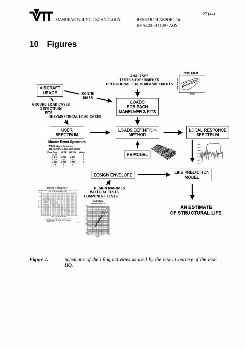
Successful fatigue management requires that the piloting techniques used by the aircrew andthe contents of flight training syllabi are brought to a level at which any life expenditurewhich is not justified by operational or training objectives has been omitted. This furtherdictates the necessity of gathering detailed information on the usage of the aircraft togetherwith all data which enable the determination of fatigue life expended by the major structuralcomponents of the aircraft in different missions and in different flight conditions therein. Asummary of the fatigue management policy is shown in Fig. 1.
2.1 Fatigue management goals
The goal for the fatigue management of the FAF can currently be formulated as follows:Adjust the contents of training syllabi and the peacetime operational usage such thatoperational and training effectiveness is maximized while simultaneously meeting a given Outof Service Date.
2.2 Fatigue management functions
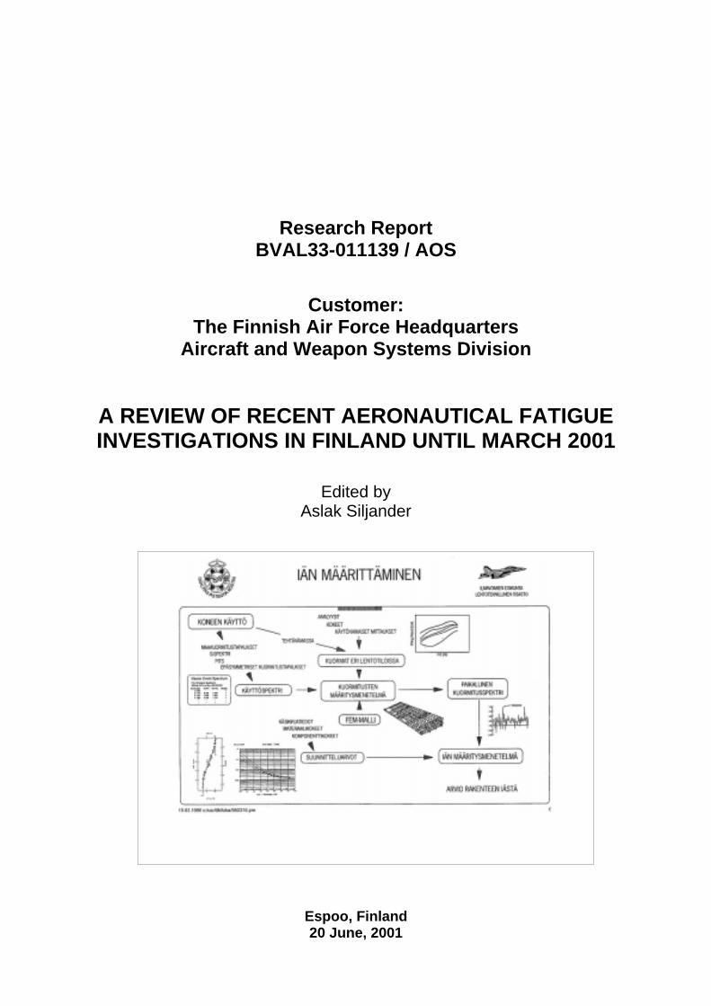
In order to maintain safety of flight, it is required that the fatigue status of the fleet, includingall major load carrying structural assemblies of each individual aircraft, can be determined insuch a way that any required structural inspections can be carried out and any structuralassemblies or whole airframes can be retired from service before or at the cleared life. In caseof highly maneuverable military aircraft, e.g. the Hornet (Fig. 2) and the Hawk (Fig. 3), wherelarge differences can exist in the severity of usage between individual aircraft, it is requiredthat the usage and the structural effects of the usage can be tracked individually for eachaircraft.
Individual aircraft are assigned to operating units and further to missions based on theexpected severity of the usage so that life is expended at an approximately even rate betweendifferent tailnumbers. This should result in a replacement window for the fleet which is ofreasonable length while simultaneously allowing for the full exploitation of available life ofeach aircraft. As an example of this is the FAF Hawk wing replacement program: The fleetFatigue Index (FI) accumulation is planned carefully for each aircraft to get the maximumbenefit of the replacement with a minimum amount of new wings.
Adding to the above, individual aircraft may be assigned to "fleet leader" roles to provideearly warnings of possible structural fatigue scenarios.
Following to the fatigue management goal of the FAF, the most important goal for any usagerecording and analysis system is to identify what types of flying (missions, configurations orflight conditions) cause most damage to the structure, in order to allow:
MANUFACTURING TECHNOLOGY
6 (44)
RESEARCH REPORT No.
BVAL33-011139 / AOS
• to confer with the aircrew to avoid flying in severely damaging flight conditionsunless specific training or operational reasons dictate otherwise
• the adjustment of the content of the training syllabi so that flying in severelydamaging flight conditions is minimized without compromising training objectives
Data must be collected on occurrences of cracks, etc., found which are to be combined withusage data to produce estimates for the rest of the structure and the rest of the fleet to be usedin decision making on pre-emptive modifications. Same type of data can be used in the designof repairs and modifications.
Furthermore, available data and understanding on the fatigue properties of the FAF aircraftstructures should be on the level which allows the training of aircrew, technical personnel,planners and managers to meet the objectives outlined above.
2.3 Fatigue management data requirements
Quantitative, calibrated data on fatigue life expenditure rates are required:
• form each aircraft (tailnumber), from the most critical structure (e.g. Figs. 2 and 4),to allow for aircraft retirement decisions and comparisons between pilots andoperating units
• from all critical structural assemblies from a large enough sample of flights toallow for the determination of average
− damage rates / mission type / structural location
− damage rates / flight condition / structural location
It is required that the flight condition and damage data collected during a flight can becombined with flight log data identifying the mission type, operating unit, pilot, etc.
For the FAF F-18 aircraft, the following can be added: It is also required that the master eventspectrum together with loads and material data used in the design are available, together withrelevant software, to allow a quantitative assessment of the effects of differences betweendesign and true FAF usages to the lives of all critical structural assemblies. This allows for theidentification of highly damaging flight conditions within the training syllabi and allows forthe focusing of corrective measures where the payoff is the greatest.
2.4 The scope of the national review
This national review of current aeronautical fatigue investigations in Finland is published forthe first time. Therefore, a brief introduction of the aircraft inventory of the Finnish Air Force(FAF) is justified, Table 1. The emphasis of this national survey is on the three mostimportant aircraft types of the FAF, namely the primary trainer Valmet Vinka (VN), the jettrainer Hawk Mk.51 and Mk.51A (HW) and the F-18C/D Hornet (HN).
Finland is willing to seek for the ICAF membership, for which the current review in Finlandis collected and delivered. This review also forms a step in Finland towards the internationalcommunity of aeronautical fatigue research.

MANUFACTURING TECHNOLOGY
7 (44)
RESEARCH REPORT No.
BVAL33-011139 / AOS
3 On the Valmet Vinka’s LEPThe Life Extension Program (LEP) of the Valmet Vinka primary trainer, also known as theValmet L-70 Miltrainer Vinka [Air International 1979] is covered in a more thorough mannerby PFA in another ICAF 2001 presentation [Pirtola 2001]. For the sake of the first Finnishnational review, however, a brief overview of the program is provided below (Fig. 5).
The most important areas of interest of the aircraft’s structures were modeled (FEM) by PFA.Meanwhile at the FAF, the actual sortie distribution corresponding to the FAF use of theVinka was updated. Fatigue critical areas of the aircraft were also identified and preliminaryestimates of their fatigue lives were produced [Pirtola 2001]. Subsequently, more detailed FEanalyses of the wing carry-through area were conducted by PFA. Supporting life estimationactivities were provided by HUT/LLS [Wallin 1997/1].
A series of flight measurements were performed with one aircraft that was instrumented witha data recorder (strains, normal acceleration, airspeed and altitude) [Vuorio, Teittinen,Siljander 1996]. The purpose of flight measurements was to collect data representative oftypical FAF maneuvering and to update the existing flight loads analysis database of PFA.The strain gages were fitted to wings, wing carry-through, tailplane, fin, aft fuselage andengine support structures. To account for all loading conditions of interest (maneuvering anddynamics), all responses were sampled at 3600 samples per second.
Based on the actual sortie distribution of the aircraft in the FAF usage and on VTT’s flightmeasurements during various sorties, the representative load spectrum was generated andfatigue life estimates were made [Pirtola 2001]. The fatigue and damage tolerance analyses ofthe wing carry-through were made also at Saab in Sweden [Berg 1998; Ansell 1998]. On thebasis of the analysis results, some fleet inspections were made within the FAF.
To verify the analysis results, fatigue test components representative of the wing carry-through region were designed and manufactured by PFA [Lahtinen 1999; Pirtola 2001]. Theuniaxial and variable amplitude fatigue tests were performed by VTT [Laakso 1999]. Somestrain gage locations corresponded to those of the test flight instrumentation. These strainvalues together with the normal acceleration data of the aircraft provided reliable means tocorrelate the axial load to the strains and normal acceleration. To allow direct comparisonsbetween the experimental fatigue life to the predicted values, the fatigue test load spectrumwas that of previously employed in the analytical and numerical durability assessments.During the fatigue tests, fatigue crack formation and growth from all boltholes weremonitored using the Eddy Current technique (ET). In connection with the ET, the roundnessof the boltholes, bolt rotation and bolt tightening moments were among the items monitoredthroughout the spectrum fatigue tests.
As a result of the LEP program, a safe life of 5000 FH of the FAF representative flying wasverified. Furthermore, the design effort is underway to extend the safe life to 7000 FH.
MANUFACTURING TECHNOLOGY
8 (44)
RESEARCH REPORT No.
BVAL33-011139 / AOS
4 Hawk Mk.51 and Hawk Mk.51A
4.1 Hawk jet trainers in Finland - overview
A brief structural description of the Hawk aircraft can be found e.g. in reference [O’Hara1993]. In 1976, a decision within the FAF was made to purchase 50 Hawk Mk.51 jet trainersto replace the FAF’s aging Fouga Magister jet trainers. Four Hawks were assembled inEngland, while 46 aircraft were assembled at Valmet Aircraft Factory (currently PFA) inKuorevesi, Finland. The tailplanes, fins, ailerons and air brakes of these aircraft were alsomanufactured by Valmet Aircraft Factory. Finland was the first export customer to the Hawkjet trainer.
The first flight of the Finnish-assembled Hawk Mk.51 aircraft (tailnumber HW-301) tookplace in January 1981, and the last aircraft (HW-350) was handed over from Valmet to theFAF in October 1985. The FAF made an additional order of seven Mk.51A aircraft inDecember 1990; these aircraft were all assembled in England by June 1994. Today, there arein excess of 165,000 flight hours with the FAF’s Hawk inventory.
4.1.1 First actions triggered by the need
During the years it was observed that the FAF’s usage of the Hawk was markedly more severethan that of the original design (Fig. 3). As a consequence, the first fatigue related structuralfailures were observed in Finland at the end of the 80’s. These structural issues were repairedat PFA according to the existing repair instructions made by the manufacturer (then BAe, laterBAE Systems) and PFA (then Valmet Aircraft Factory). During mid-90’s, a number of Hawktailplanes were "grounded" for the first time due to certain CSI’s (Company StructuralInspections issued by BAE Systems) that came in effect. Additionally, information providedfrom BAe on their full scale fatigue test results and from other Hawk users on their fleetexperience indicated that one should be prepared for various structural fatigue issues (inaddition to the tailplane) within a relatively short time. These indications provided additionalchallenges, since some of the structural-issues-to-come were either such that there were noapproved repair schemes, or the life improvement gained while applying some of theapproved repair instructions was not acceptable.
4.1.2 The LEP feasibility study
The FAF HQ invited BAe to conduct a LEP feasibility program for the FAF Hawks with agoal to achieve the 6000 FH. To get the longest structural life with minor technical risks,heavy structural modifications were suggested: replacements of the wing, aft fuselage, fin andtailplane. At the same time within the FAF AMC, the FAF squadrons and PFA, somestructural damages needed immediate actions. The proposed modifications - if implemented -could have provided structurally upgraded (over 6000 FH) Hawk fleet for the FAF, butwithout upgrading of the avionics systems. Furthermore, the time and money spent as well aspossible training syllabi distraction aspects emphasized more economical and rapid actions.Consequently, the FAF invited PFA to create a repair and rework package for the known andthe most probable failure scenarios.

MANUFACTURING TECHNOLOGY
9 (44)
RESEARCH REPORT No.
BVAL33-011139 / AOS
4.1.3 Follow-up actions
Parallel to the LEP feasibility activities described above, the FAF AMC and PFAconcentrated their efforts in developing own repair methods and applying them on the FAF’sfleet aircraft. Between 1997-1999, there were numerous new (to the FAF) crackingobservations requiring immediate repairs. In fact, until the early ’98 the repair activities at theFAF AMC and PFA were conducted step by step from the most critical parts to the lesscritical. Either the repairs were planned and implemented as a structural issue would emergeor where it was known they would emerge soon. The experience of BAE Systems and theUnited Kingdom Royal Air Force (RAF) on Hawk proved very useful and enabled fruitfuldiscussions and exchange of experience in e.g. analysis methods.
Based on the experience gained along the activities, the solution selected case-by-case was apartial combination of structural analysis using analytical or numerical methods (parallelcontinuation with the FE modeling and analysis efforts at PFA), flight measurements,modification planning and modifications. Supporting activities included those of VTT (flightmeasurement and damage tolerance analyses), BAE Systems (structural understanding andfatigue tests results) and the FAF (usage analysis). Today, e.g. an experimentally verified 3Dfinite element model of the aircraft exists at PFA. Further, PFA and the FAF AMC havedeveloped repair and modification kits for e.g. ventral strakes, flaps, gun pod, aft fuselageframes and wing panels.
The first version of a Finnish repair and rework plan was created during 1999. There was aneed for additional studies on the probability of certain failure types. These studies wereperformed, and by the end of 2000 PFA had completed the design work for all expectedstructural damage scenarios, e.g. [Raunio 2000; Raunio 2000b]. These scenarios wereclassified into three categories, of which the most critical scenarios will be repaired ormodified in a pre-emptive manner during the routine aircraft maintenance. The second mostcritical scenarios will be dealt with as they appear. The least significant scenarios will eitherbe ignored or only schematic repair schemes will be considered.
The pre-emptive modification plans for the fin and wing leading edges were developed atPFA at the end of the 90’s e.g. [Raunio 1996]. The current investigative efforts on the FAFHawks are focused on the durability assessments of the fatigue critical areas of the originalwing and on the development of the inspection procedures e.g. with the aid of fracturemechanics applications. The existing FE model of the Hawk (Fig. 6) at PFA has beencombined from partial FE models which have been created step by step: the tailplane[Keinonen 1997b], the center fuselage [Keinonen 1998], the Mk.51 empennage [Keinonen &Tikka 1999], the fin [Lähteenmäki 1999], the Mk.51 wing [Tikka 2000b] and the forwardfuselage [Tikka 2000c]. The aerodynamic loads for symmetric and non-symmetric load casesare evaluated using CFD. Fig. 7 summarizes the most important Hawk activities. In thefollowing, the major aspects are reviewed.

MANUFACTURING TECHNOLOGY
10 (44)
RESEARCH REPORT No.
BVAL33-011139 / AOS
4.2 Tailplane and empennage
The project consisted of the following elements: rework and refurbishment planning andengineering, numerical modeling of the structures, analytical and numerical fatigue lifepredictions, structural response measurements during test flights, experimental fatigue tests ofselected components, as well as the development of a new inspection system and theassociated procedures. Some of the activities are described below.
4.2.1 "Mini-OLM I" flight measurements
A part of the plan [Raunio 1997] was the instrumentation of one Hawk aircraft such that theflight maneuvering and buffet induced responses could be captured during selected test flightsrepresenting the FAF usage. These test flights and the associated research activities includingthe tailplane, fin and empennage are termed as a "mini-OLM I" excercise [Vuorio, Teittinen,Aatola, Siljander 1997]. These flight response data, together with the Hawk fleet usage data ofthe FAF, the maintenance records of the FAF and PFA, and PFA’s FE analysis results of theHawk structural FE model would then be used in subsequent engineering assessments of theeconomical service life of the tailplane.
The instrumentation consisted a total of 18 channels of response data: 10 tailplane strains, 2fin strains, 2 wing strains, 2 tailplane accelerations, normal accelerations from the aircraft’scenter of gravity (NZ) and from the tailplane attachment main frame inside the aft fuselage.Most of the strain gage channels were instrumented in global net sections such that theresponse results could be compared to those obtained by the manufacturer from the RAFOLM response results [O’Hara 1993] and PFA’s FEA results.
The manufacturer had earlier discovered significant buffet-induced responses of the tailplanewithin the frequency range of approximately 70 Hz...100 Hz [O’Hara 1993]. Therefore, anexperimental modal analysis of the tailplane region was conducted before the flightmeasurements. The goal was to capture the modal shapes within the frequency range of 10Hz...100 Hz. A fully functional tailplane, mounted to the empennage at the neutral position,was excited using the impact hammer technique.
To gain understanding of the relation between pilot actions and the responses, all standardflight parameters were captured in a synchronized manner with the strain and accelerationresponse data. The flight parameters were collected using the TIIKERI+ onboard flight testinstrumentation system developed earlier by the FAF and PFA and routinely used by the FAFFlight Test Center. All strain and acceleration response signals (3000 samples per secondeach) together with the aircraft parameter data from the TIIKERI+ system (20 samples persecond) were stored on a digital data recorder. An example of the response data is shown inFig. 8.
MANUFACTURING TECHNOLOGY
11 (44)
RESEARCH REPORT No.
BVAL33-011139 / AOS
4.2.2 Determination of the aerodynamic loads using CFD
During the rework and rework planning and engineering of the FAF Hawk tailplane, thecomputational fluid dynamics (CFD) and finite element modeling and analysis (FEM & FEA)were combined for the first time in Finland for aeronautical applications.
The calculations of aerodynamic loads for the Hawk were started at HUT in late 1996 bystudying the tailplane at a few maneuvering conditions [Hoffren & Pietilä 1997]. Since thecases were essentially subsonic and no flow separation was involved, the calculations in theLaboratory of Aerodynamics were performed by applying a panel method for the full aircraft.The useful results led to the continuation of the load calculations at HUT, but because of theinherent limitations of the inviscid panel methods, the panel methods had to be abandoned atthis stage. To be able to simulate a transonic, viscous flow around the wing with sufficientaccuracy, the Navier-Stokes flow solver FINFLO developed at the Laboratories ofAerodynamics and Applied Thermodynamics was employed. However, the use of theFINFLO is very expensive for the whole flight envelope. Therefore, a combination of the useof the panel method and the FINFLO was employed, and the aerodynamic loads wereinterpolated for a structural model of the Hawk [Tikka 2000]. The calculated wing loadscompared favorably against measured data.
Viscous navier-Stokes simulations were performed at 11 different flight conditions using asteady-state assumption. Since the actual state of the flow field is in some cases, e.g. in a caseof a pull-up, time-dependent, suitable approximative approaches were utilized. Thecomputations were performed at HUT using a FINFLO flow solver. The flow solver is basedon the standard state-of-the-art methods related to structured grids. A compressible form ofthe Reynolds-averaged Navier-Stokes equations is used. The scheme is cell-centered andbased on a multiblock grid topology. The code contains several possibilities for turbulencemodeling. In the present cases two-equation k-epsilon- and k-omega -models have beenapplied. The solution methods of FINFLO are described in more detail in [Siikonen 1995].
At symmetrical flight conditions a half of the aircraft was modeled. The computational gridconsists of 3.8 million cells. In asymmetrical cases the whole aircraft was modeled and theresulting grid consists of 7.6 million cells. A surface grid of the aircraft can be seen in Fig. 9.
An example of the unsteady situations simulated using steady-state assumption is a pull-up.The numerical simulation of the pull-up differs only slightly from a simulation in straighthorizontal flight, but the effect in the computed flow field is large. In the simulation of thepull-up the aircraft is in an angular pitching motion. As a consequence of the angular velocity,the flow field relative to the aircraft is curved and this changes the pressure distribution andthe aerodynamic forces acting on the aircraft's surface. The pull-up condition is modeled bysetting the external flow field to rest and putting the grid into circular motion. For thispurpose the flow equations are transformed into a rotating reference frame. The computationalprocedure and some results are described in [Siikonen, Rautaheimo, Salminen 2000]. As anexample, a surface pressure distribution and streamlines are given in Fig. 10.
In symmetrical flight conditions the agreement in aerodynamic loads obtained by CFD andtest flights was excellent. The same agreement was not obtained in rolling conditions. Thiswas assumed to be due to the difficulties in keeping the aircraft exactly in the desired flightcondition during the rolling motion in flight tests.
MANUFACTURING TECHNOLOGY
12 (44)
RESEARCH REPORT No.
BVAL33-011139 / AOS
4.2.3 Fatigue life assessment of fin spar/skin joints
As a part of the HW empennage structural life assessment program of the FAF and PFA, thefin spar/skin joints were analysed by HUT/LLS. The study revealed that it is possible toestimate the fastener load distribution with a simplified FE-model where the fasteners aremodeled as beams that are connected to plates with single nodes. An enhanced model of thejoint was further constructed using solid elements in plates and in fasteners and a contact wasused in all relevant areas. The analyses did not predict the critical location of the jointcorrectly [Wallin 2001].
Constant and variable amplitude fatigue tests of the fin skin-to-spar structural joints (three-row simple lap joint with Hi-Tique fasteners) were conducted by HUT/LLS [Wallin 2001].The purpose was to find out whether it is possible to derive the fatigue life of the joint fromthe fatigue data of smooth and notched specimens. The stress concentration factor of thenotched specimen corresponded to the severity factor of the joint specimen. The fatigue testspectrum was generated by PFA [Keinonen 2000] on the basis of the "mini-OLM I - severelybiased" flight trial strain responses. The tests revealed that the fatigue behavior of the jointcould not be derived from the fatigue data of smooth or notched specimens. Reasonablevariable amplitude fatigue life estimates were achieved from constant amplitude fatigue dataof the joint specimen.
Round robin style fatigue life prediction activities took place between PFA and VTT [Koski2000] such that the same test spectrum was employed [Keinonen 2000]. The purpose of thefatigue life predictions was to validate the numerical models and the life estimationalgorithms. The fatigue life estimations at VTT were based on the combinations of fatiguecrack initiation and fatigue crack growth. An overview of the above is illustrated in Fig. 11.
Additional fatigue tests were performed for specimens representing the Hawk tailplane strapjoint [Aakkula, Wallin, Jussila 1997; Aakkula 1998]. Reference data was also established byfatigue testing some generic joints [Aakkula & Wallin 1997/1,2,3].
4.2.4 Fatigue life assessment of the tailplane region
Simplified test specimens simulating the actual butt strap joint of the tailplane were designedand manufactured by PFA, including strength and durability analyses using numericalmethods [Keinonen 1997]. Fatigue tests were performed for the specimens by HUT/LLS[Aakkula, Wallin, Jussila 1997; Aakkula 1998]. Reference data was also established byfatigue testing some generic joints [Aakkula & Wallin 1997/1,2,3].
To aid the analysis of the above fatigue test results, the fatigue crack growth characteristicsemanating from the edges of fastener holes were emphasized in the analyses. The predictedcrack growth rates varied notably, depending on e.g. load spectrum characteristics and on theinitial stress state (e.g. degree of the fastener pre-stress) [Keinonen 1999; Koski & Bäckström2000]. The above investigations are summarized in Fig. 12.

MANUFACTURING TECHNOLOGY
13 (44)
RESEARCH REPORT No.
BVAL33-011139 / AOS
4.3 Center fuselage
After the tailplane and empennage activities, the main interest was focused on the next mostimportant entity, namely the center fuselage. The center fuselage’s durability is mainlygoverned by pressure cycles within the main fuel tank. The first activity at PFA was thedesign and implementation of the pressure relief valve modification for all FAF Mk.51 Hawkaircraft [Raunio 1998], since even with coarse analytical methods it was evident that thepressure cycle due to the refueling of the aircraft produces significant fatigue lifeconsumption.
Subsequent activities included the center fuselage rework planning and engineering on thebasis of known fatigue critical areas. These areas included three bulkhead frames and themain fuel tank’s inner sidewall, e.g. [Raunio 1997b; Raunio 1997c]. To support the FAFHawk center fuselage rework activities of the FAF and PFA, a cooperative concept similar tothat described earlier was again conducted.
4.3.1 Strength and durability analyses with and without compositereinforcements
Fatigue life assessments of the original main fuel tank area (i.e. the center fuselage withoutreinforcements) were carried out. The fatigue life predictions were based on the stress life[Keinonen 1998b, Keinonen 2000d] and crack growth calculations [Koski, Bäckström,Siljander, Wallin; 1999]. VTT's crack growth analyses concentrated on the multi-site-damage(MSD) effects, Fig. 13.
Together with the investigations at PFA using the numerical model of the center fuselage[Keinonen, 1998], various reinforcement techniques within the center fuselage region werestudied by PFA and HUT/LLS [Pätynen 1998; Pätynen 1998b; Raunio 1999; Aakkula &Wallin 1999]. The purpose of the reinforcement modification investigations was to reduceoperational stresses and to protect the fuel bag from puncture, which could happen if theadjacent structures would experience fatigue damage. A scrapped center fuselage wasavailable for e.g. the mould lining and reinforcement investigations.
Small-scale specimens representing the actual structures were further prepared [Keinonen2000b; Aakkula & Wallin 1999]. Some of the specimens were instrumented, tested usingstatic loads [Aakkula 2000; Teittinen & Siljander 1998] and fatigue tested [Aakkula 2001;Teittinen & Liukkonen; 2000]. The test specimen geometry and instrumentation is shown inFig. 14.
A candidate reinforcement structure was manufactured by PFA and HUT/LLS and installed inthe scrapped center fuselage which was then pressure tested [Liukkonen, Teittinen, Siljander1999], Fig. 15. Based on the results, the final reinforcement configuration was fitted to thescrapped center fuselage. A new set of pressure tests was performed to quantify the stresses atcritical locations [Liukkonen, Teittinen 2000].
In addition to PFA's strength and durability analyses of the reinforced center fuselagemodification, the crack growth analyses will be conducted in near future.
MANUFACTURING TECHNOLOGY
14 (44)
RESEARCH REPORT No.
BVAL33-011139 / AOS
4.3.2 "Mini-OLM II" and "Mini-OLM III" flight measurements
A decision was made to collect center fuselage response data from dedicated test flights. Theinstrumented test flights were aimed at gaining and providing understanding of themechanical behavior of the actual structure subjected to the FAF maneuvering, as well as toprovide experimental data for the validation of the entre fuselage region’s global and localnumerical models.
The instrumentation for the center fuselage mini-OLM test flights ("mini-OLM II") consistedof 17 response channels (15 strains, 1 acceleration and the pressure difference between thefuel tank interior and outside) [Teittinen, Siljander, Liukkonen 1998]. An updated version ofthe TIIKERI+ flight parameter data acquisition unit with its 59 parameter monitoring featurewas also utilized. The strain gage locations and bridge configurations were selected aiming atthe commonality and comparability to those of the aircraft manufacturer. All data was againstored on a data recorder installed onboard the aircraft.
The mechanical calibration of the response tranducers on ground consisted of a series ofgravity refuelings and defuelings, as well as those with full fuel system pressure. Test flightswith a constant aircraft configuration at different altitudes and with different fuel amountswere performed, including individual maneuvers, air-to-air combat, and aerobatics.
The identical reinforced center fuselage configuration as described in the previous chapterwas then realized in a Hawk aircraft. The structure was instrumented with strain gages, andthe flight-induced responses were captured from test flights ("mini-OLM III") to verify theanticipated mechanical behavior and stress-reducing effects due to flight-induced loads. Toallow comparisons of the results with the "mini-OLM II" flight test response data, the "mini-OLM III" flight test program was nominally identical to that of the "mini-OLM II" excercise.The analyses of the results are ongoing.
4.4 The OLM program
The "mini-OLM" programs described in previous chapters were aimed at quantifying thedurability and flight safety aspects of certain structural assemblies only, such that theresponses were captured only from specific maneuvering events. For fleet managementpurposes, and to verify the conclusions derived from the limited scope flight tests (the mini-OLMs), and also to gain statistically reliable data of the entire Hawk airframe in routine FAFusage covering all maneuvering possibilities in the FAF training syllabi, differences betweenoperating units and piloting techniques, etc., a separate OLM program was initiated.
The OLM system design and delivery responsibility is with the original aircraft manufacturer,BAE Systems. PFA is responsible for the installation of the aircraft parameter transducers andall cabling and the system maintenance. VTT is responsible for the strain gage installation andtheir maintenance as well as the response data analyses using the ground stations and softwareprovided by BAE Systems.
Two FAF aircraft have been equipped with over 50 strain gages, accelerometers, aircraftparameter transducers and onboard data acquisition units, Fig. 16. The first aircraft (HW-348)was delivered to the FAF in July 2000 and the second one (HW-319) in March 2001.
The two aircraft are being used in reqular FAF service in such a manner that all trainingsyllabi and other usage will eventually be covered. The use of the aircraft is managed suchthat the mission types which are considered more damaging to the structure are flown early onin the program.

MANUFACTURING TECHNOLOGY
15 (44)
RESEARCH REPORT No.
BVAL33-011139 / AOS
The OLM program will be a "rolling program", i.e. the OLM-equipped aircraft will stay inservice and the recorded data will be analyzed until the retirement of the Hawk from the FAFservice.
5 F-18C/D HornetThe FAF has a total of 64 F-18 Hornets in its inventory (7 D’s and 57 C’s). The D modelswere assembled in the USA by Boeing, while the C models were assembled in Finland byPFA. The first D models were flown to Finland in November 1995 and the last C-model wasdelivered to the FAF in August 2000.
The FAF F-18 Hornet has an onboard fatigue tracking system based on 7 strain gages and anumber of aircraft parameters. These data are sampled and stored onboard during each flight.The damage analysis is made on ground by strain life method using the SAFE software. Thedamage rates (FLE; fatigue life expended) for each flight, including all essential flightinformation, are attached into the FAF flight log database. Examples of the data extractedfrom the FAF database are shown in Figs. 2 and 4. From the database, fatigue reports can bemade per mission code, pilot, squadron, etc. The FAF Hornet fatigue life usage has been moresevere than expected, although the damage accumulated per each year is anticipated to begoing to the better direction.
5.1 On investigations preceeding the HOLM program
During the past five years, several small investigations have been conducted within the FAFand PFA to e.g. better understand the operation of the onboard fatigue tracking system, itsfunctions, etc. Further, the ground station environment (SAFE), which is used to analyze theonboard data after each flight, has been continuously developed at PFA and the FAF to bettersuit to the Finnish needs.
Since 1996 Finland has participated in the operation of two international working groups ofthe F/A-18 users – IFTWG (the F/A-18 International Fatigue Tracking Working Group) andCREDP (the F/A-18 Composite Repair Engineering Development Program). The informationexchange within these working groups with the other F/A-18 user countries (the USA,Canada, Australia, Switzerland) is useful and significant for the future of the structuralintegrity work of the FAF F-18.
The current fatigue tracking system was evaluated by VTT [Siljander, Liukkonen, Teittinen,Hedman 1999]. As a result of the evaluation, it was found out that the current system does notfully match to the needs of the FAF and it does not provide information from the entirestructure.
PFA conducted another investigation on the current fatigue tracking system [Orpana 2000].Features such as temperature compensation, low sampling rate and absence of antialiasingfiltering of the current system on the fatigue tracking results were among the goals of thestudy. The strains from the onboard strain gages were recorded during selected flights using 3parallel measurement systems onboard: The current system (20 Hz sampling rate), theALBUS flight recording system (20 Hz) of the FAF and a commercial system (SWIFT) ofPFA (1000 Hz and 2000 Hz were used). The results of the project indicated e.g. that the 20 Hzsampling rate of the current onboard system is adequate for 3 of the 7 strain gages, and for theother four gages the sampling rate should be markedly higher.
MANUFACTURING TECHNOLOGY
16 (44)
RESEARCH REPORT No.
BVAL33-011139 / AOS
5.2 The HOLM program
The experience gained in developing applied mechanics tools to cope with aging aircraftstructures of the FAF are being tailored to the FAF F-18C/D aircraft. A decision has beenmade at the FAF to initiate the HOLM (Hornet Operational Loads Measurement) program insupport of the FAF fatigue management principles. The work will contain principally similarelements as described previously for the Vinka and Hawk aircraft.
A research Statement of Agreement (SoA) has been signed between the FAF, PFA and VTTon the HOLM program. The HOLM program is divided in three phases: HOLM research,HOLM prototype and HOLM production. The creation of detailed work packages and theactivities therein are underway (Fig. 17). General description on the HOLM research phase isprovided in the following.
• Structural information, structural software and possibilities to integrate the HOLM(production) system to the aircraft are being evaluated with the aircraftmanufacturer.
• The aircraft related non-destructive inspection (NDI) activities underway at VTTform a step in Finland towards developing NDI methods capable of detectingfatigue cracks from the fatigue critical structural details of the FAF F-18, includingthe IVD coated and peened aluminum components [Jeskanen et al 2001]. The workis being done partially together with the DSTO/AMRL (Defence Science andTechnology Organisation/Aeronautical and Maritime Research Laboratories,Melbourne, Australia).
• Structural modeling on the basis of the FEM specification [Lähteenmäki 2000] ofthe main airframe is underway at PFA.
• CFD analyses, using the FINFLO software are being done at HUT.
• Fatigue critical structural parts assessment corresponding to the FAF usage and thestructural modification level is underway at the FAF, PFA and VTT.
• Alternative solutions for the onboard system will be assessed by VTT to come upwith a data acquisition system capable of e.g. collecting, preprocessing and storinganticipated quantities with adequate sampling characteristics to capturemaneuvering and dynamics induced responses. The avionics integrationspecification will be done at PFA. This forms the first phase (HOLM research).
During the second phase, a prototype will be designed, which will be installed to a limitednumber of the FAF F-18 aircraft (phase 3). These response data will eventually be used aswith the FAF Hawk OLM.
MANUFACTURING TECHNOLOGY
17 (44)
RESEARCH REPORT No.
BVAL33-011139 / AOS
6 Related ActivitiesThis chapter summarizes investigations of general nature that serve one or more of the FAFaircraft types covered in previous chapters and in Table 1.
6.1 On data acquisition and analysis efforts
Due to the sample rates employed in the flight measurements performed by VTT, the amountof stored response data is noteworthy. Therefore, one of the main activity areas at VTTassociated with the flight measurements and the data analysis environment therein has beenon developing features related to the management (e.g. postprocessing) of the bulk of thestored data. The analysis environment existing at VTT prior to the flight measurements hasevolved over decades of man-years, principally on maritime but also on ground applications.The data management requirements of these applications may be similar to those of theaircraft applications, but e.g. the size and weight requirements of the measurement hardwarediffer by at least by an order of magnitude. Starting from the response data processing of theVinka flight measurements, the analysis environment has been continuously developed, as theamount of flight data has increased from a flight test to another.
To gain a thorough understanding of the structural behavior in view of fatigue lifeconsumption of e.g. an aircraft, it is vital to have the ability to study pilot control inputs(aircraft parameter data) and the response signals characterizing the structural behavior(strain, acceleration etc.). Based on the experiences obtained while analyzing the "mini-OLMI" data, methods were investigated and developed to integrate all measured quantities into onesoftware. Within the software developed it is possible to e.g. "zoom" into selectedmaneuvering/dynamic events such that a reliable synchronization between the anticipatedquantities exists [Liukkonen, Siljander, Teittinen, Hedman, Koski 1998]. The data from the"mini-OLM I" exercise were used as an input for the investigative efforts.
6.1.1 WEAG RTP 3.20: "AHMOS"
The project AHMOS (Advanced Structural Health Monitoring Systems) is a joint EuropeanResearch and Technology Program (RTP 3.20) under the Western European ArmamentGroup (WEAG). The participants in the on-going program are: EADS (Germany; the singleleading industrial entity); BAE Systems, DERA and Smart Fibres (England); Alenia andCIRA (Italy); CASA, INTA and UPM (Spain); CSL (Belgium); DEMEX and Risoe(Denmark), Fokker Services and NLR (the Netherlands); PFA and VTT (Finland).
The objective of the RTP is to define, develop and demonstrate structural health monitoringsystems capable of being applied to military platforms (e.g. military aircraft). The systemswill include the necessary sensors, signal processing, data storage, analysis and presentation.Techniques for incorporating the sensors into the structure and consideration on how thesystem will be integrated into the platform will be considered. The complexity of the systemmay vary – via modular design - depending on the platform and on the materials used. Thisvaries from a system able to detect and locate impacts likely to cause damage, to a systemcapable of determining the integrity of the structure at any time. The overriding objective,however, will be to demonstrate practical systems which will reduce the cost of ownership byreducing inspection and maintenance costs, and to extend the life of the military platforms inquestion. An example of an implementation scenario is shown in Fig. 18.

MANUFACTURING TECHNOLOGY
18 (44)
RESEARCH REPORT No.
BVAL33-011139 / AOS
6.2 Development of fatigue analysis tools
A simple software for Palgren-Miner analyses of aircraft structures was developed byHUT/LLS in 1999 [Wallin & Karttunen 1999]. The work included the integration of VTT’sRainflow counting algorithm into the software. A tool for fitting test data or SN-curves fromliterature to a numerical format was also developed. The software includes databaseconsisting of SN-curves for most typical materials and mechanical joints found in theliterature [Wallin 1999/1]. Typical joints in current fleet of FAF were also identified duringthe project [Wallin 1999/2].
A literature survey on deterministic life prediction methods was performed in co-operationbetween VTT and HUT/LLS [Wallin & Koski 1999]. The deterministic models includedthose published on stress-life (infinite life), strain-life (initiation life) and fracture mechanics(residual life) and their combination methods together with each model’s assumptions,limitations and advantages. The main activity was focused on fracture mechanics applications.The most common aircraft joint types, as well as the evaluation methods of the load and stressdistributions in the vicinity of the joints were covered by the survey. The work was funded bythe Scientific Committee of National Defence (MATINE).
As a follow-up of the literature survey, the applicability of the deterministic fatigue lifeprediction methods and software was evaluated with two case studies. The work wasperformed in co-operation between VTT and HUT/LLS [Koski, Bäckström, Siljander, Wallin;1999]. The first case study was chosen from the open literature fulfilling the criteria:
• any laboratory fatigue test specimen such that its e.g. material, material thickness,hole geometry and loading were similar to those of a "typical FAF structuraldetail";
• the study should deal with multi-site-damage (MSD) effects;
• availability of experimental test results (e.g. artificially produced pre-cracklocations and dimensions, as well as crack growth rates).
With the above criteria, the first case study was chosen (Fig. 19) [Horst et al 1997]. Thesecond case study was chosen to be the rivet line of the main fuel tank within the centerfuselage of the FAF HW aircraft, Fig. 13.
Another literature survey on probabilistic life prediction methods was performed in co-operation between VTT and HUT/LLS [Wallin & Koski; 2001]. The work was a logicalcontinuation of the literature review on the deterministic methods. The survey was focused onmethods applicable for fatigue crack growth analyses. It covered the random variable methodbased on the damage tolerance philosophy and deterministic crack growth models, as well asthe method based on the concept of economic life. The effect of NDI intervals on probabilitywas also surveyed and examples of the allowable risk on different application were searched.Finally, software available for the analyses were evaluated and an analysis example ofprobabilistic crack growth was made with the random variable method. The MATINE againfunded the survey. One of the future goals is to apply probabilistic life prediction methods toon-going and new aircraft projects.
While working on fracture mechanics applications focusing on durability assessments ofaircraft structural details, a need to improve certain areas of the analyses has emerged at VTT.The following describes some of the topics that will be investigated in the future:
• The stress intensity factor solutions for cases with a complex geometry and loadingand the MSD;
MANUFACTURING TECHNOLOGY
19 (44)
RESEARCH REPORT No.
BVAL33-011139 / AOS
• The utilization of global FE model results in local BE/FE models;
• The interface aspects between local and global models;
• Generation of crack models within the local models;
The above topics will be screened and eventually applied to the analyses of suitable casestudies. Further future areas of interest include the probability based methods applied to theabove scenarios. The progress and results of these activities could be reported e.g. in thenational reviews subsequent to the ICAF 2001.
6.3 Cold working of holes in Al-plates
The effect of cold working of holes was studied by HUT/LLS in 1997 [Karttunen 1997]. Aliterature survey was accomplished to get theoretical background. Additionally, someexperimental, analytical and numerical methods were reviewed to estimate residual stressesdue to cold working. Finally, some models for predicting fatigue life and crack growth in coldworked materials were studied.
Fatigue tests were conducted to investigate the efficiency of cold working in two aluminumalloys (2024-T3 and 2014-T6). Three types of specimens were investigated: open hole, crackarrest hole and a riveted joint. The thickness of the specimens varied from 0.6 to 2.3 mm. Thetest program included 14 test series each containing 4-8 specimens. The specimens weretested using constant amplitude sine wave loading (R = 0.1, f = 10-15 Hz). Depending on thetest specimen the maximum stresses varied from 25 MPa to 175 MPa.
Cold working increased the fatigue life of the open-hole specimens by factor of four. The lifeimprovement factor of the crack arrest hole specimens was 3.8-14.2 depending on the materialthickness. With riveted joint specimens the life improvement factor was 3.3.
6.4 Repair of fatigue cracks with composites
HUT/LLS, the FAF and PFA have investigated composite repair since 1989. As a part of thework, the effect of composite reinforcements on the crack growth rate of center-cracked 1.6mm thick 2024-T3 aluminum plates was studied [Aakkula & Saarela 1995]. Thereinforcements investigated were wet laminated carbon/epoxy, carbon/epoxy-prepreg andboron/epoxy-prepreg. An alumina grit blasting followed by the silane treatment was used as asurface preparation method prior to the bonding with the vacuum bag technique. Residualthermal stresses were tailored by constraining the thermal expansion of the aluminum plateduring the curing of the adhesive, by lowering the curing temperature, and/or by raising thetesting temperature.
The repaired plates were fatigue tested at room temperature or at 70°C. The single-sidedrepairs were supported against secondary bending with edge supports or with a sandwichconstruction. The variable amplitude loading with the maximum tensile stress of 140 MPawas extracted from the FALSTAFF-spectrum.
The fatigue life of 120 000 cycles was measured for the edge-supported cracked plate withouta reinforcement. This increased to 500 000 cycles with a 1.2 mm thick carbon/epoxy-prepregreinforcement, when the thermal expansion of the Al-plate was constrained. Thecorresponding cycles were 600 000 and 980 000 for the 0.8 mm thick boron/epoxyreinforcement and for the 2.2 mm thick wet laminated carbon/epoxy reinforcement,respectively. An increase in residual thermal stresses significantly decreased the fatigue life of
MANUFACTURING TECHNOLOGY
20 (44)
RESEARCH REPORT No.
BVAL33-011139 / AOS
the specimen. Drilling of the crack arrest hole before the repair improved the fatigue life, aswell as the use of the sandwich test specimen instead of the edge supported specimen.
A pilot application of the composite repair within the FAF was a wet laminated carbon/epoxy-repair of fatigue cracks in the upper wing surface panel of the MiG-21 BIS. Several panelswere repaired since 1990 without further crack growth or bond failure. Another applicationexample is a wet laminated repair of a fatigue crack developed in the front edge of the enginecowling of the Vinka. Fatigue cracks developed in the edges of the chemically milled pocketsin Hawk’s integrally stiffened upper wing skins have also been repaired by stop-drilling thecracks, by cold working the stop-drilling holes and by bonding carbon/epoxy-prepreg patchesover the cracks [Aakkula 1996].
6.5 Fatigue of composite plates with an impact damage
The behavior of the impact damage in composite laminates in fatigue and static loading wasinvestigated experimentally and theoretically by HUT/LLS in 1994-97. The purpose was tofind out the main factors affecting the delamination and impact damage growth insimultaneous compression (or tension) and shear loading. A test fixture was designed to applythe loading to a plate specimen [Wallin 1994].
The materials used in the tests were glass fiber/epoxy and standard modulus carbonfiber/epoxy. Circular and elliptical single delaminations were simulated with Teflon inserts.Different orientations of the elliptical delamination in respect to the loading direction werestudied. The impact damages were produced with different impact energies using a dropweight impactor. The specimens were tested with different compression to shear ratios[Wallin 1997/2].
Delaminations and impact damages of the glass fiber/epoxy specimens did not grow in thetests with load levels that are typical in the design of the GFRP structures. Tests of CFRPspecimen pointed out that the load for onset of the impact damage growth is significantlylower than the load for the onset of the delamination. The impact damage can grow withrelatively low loads that are common in practical structures. The shear loading significantlyreduces the strain level needed for the crack growth. The crack growth rate in tests wasgenerally slow and it is possible that crack growth slows down and stops. However, it is alsopossible that a sudden failure occurs because of an overload only about 30% higher than theload used in fatigue tests.
7 SummaryThe transition within the Finnish Air Force from older jet aircraft to newer ones with e.g.notable maneuvering capabilities forced the FAF to initiate systematic efforts to ensure theaspects related to the flight safety and economy of the most important aircraft types of theFAF. These efforts, which are aimed at improving the national capability to cope with themany structural fatigue effects are reviewed. The fatigue management functions describedherein have formed a solid co-operative base and this know-how will be further developed tomeet the structural challenges ahead.
MANUFACTURING TECHNOLOGY
21 (44)
RESEARCH REPORT No.
BVAL33-011139 / AOS
8 List of referencesAakkula J.J. 1996. Composite Repairs of Hawk Mk.51 Upper Wing Skin Fatigue Cracks.Patria Finavitec, Report HW-L-0007 (in Finnish, classified). Patria Finavitec Oy, Halli 1996.
Aakkula J.J. 1997. Fatigue testing of the Hawk horizontal stabilizer strap joint specimens,Part 2. Helsinki University of Technology, Laboratory of Lightweight Structures, ReportKRT-T151, 1997 (in Finnish, classified).
Aakkula J.J. 2000. Fatigue Testing of Small Scale Specimens Representing the Hawk FuelTank Area Side Panel Structures and Reinforcements. Helsinki University of Technology,Laboratory of Lightweight Structures, Report KRT-T180, 2000 (in Finnish, classified).
Aakkula J.J. 2001. Fatigue Testing of Small Scale Specimens Representing the Hawk FuelTank Area Side Panel Structures and Reinforcements, Part 2. Helsinki University ofTechnology, Laboratory of Lightweight Structures, Report 01-T194, 2001 (in Finnish,classified).
Aakkula J.J., Saarela O. 1995. Fatigue Crack Growth in Aluminium Plates Repaired withComposite Reinforcement. ICAF 95 Symposium, 3-5.5. 1995, Melbourne, Australia.
Aakkula J.J., Wallin M. 1997/1. Fatigue Testing of Steel and Titanium Hi-Lok Fastener JointSpecimens. Helsinki University of Technology, Laboratory of Lightweight Structures, ReportKRT-T141, 1997 (in Finnish, classified).
Aakkula J.J., Wallin M. 1997//2, Fatigue Testing of Cold Worked Riveted Joint Specimens.Helsinki University of Technology, Laboratory of Lightweight Structures, Report KRT-T142,1997 (in Finnish, classified).
Aakkula J.J., Wallin M. 1997/3. Fatigue Testing of Cold Worked Riveted Joint Specimens,Part 2. Helsinki University of Technology, Laboratory of Lightweight Structures, ReportKRT-T143, 1997 (in Finnish, classified).
Aakkula J.J., Wallin M. 1999. Side Panel Reinforcements of the Hawk Fuel Tank Area, FinalDesign. Helsinki University of Technology, Laboratory of Lightweight Structures, ReportKRT-T162, 1999 (in Finnish, classified).
Aakkula J.J., Wallin M., Jussila J. 1997. Fatigue Testing of the Hawk Horizontal StabilizerStrap Joint Specimens. Helsinki University of Technology, Laboratory of LightweightStructures, Report KRT-T136, 1997 (in Finnish, classified).
Air International 1979. Valmet L-70 Miltrainer (Vinka). Air International 1979, December 1979.
Ansell, H. 1998. Damage tolerance analysis of the lower steel beam (knife) of the wing tofuselage joint. FKH-98.84. Linköping 1998 (classified).
BEASY. BEASY Users Guide. Computational Mechanics BEASY Ltd. Ashurst Lodge, AshurstSouthampton. http://www.beasy.com
Berg, K. 1998. Fatigue analysis of critical areas in the wing-fuselage joint for the Vinka A/C.NDK-98.016. Linköping 1998 (classified).
ESACRACK. ESACRACK User's Manual. ESA PSS-03-209 Issue 2. 1995. European SpaceAgency.
FRANC2D/L: A Crack Propagation Simulator for Plane Layered Structures. Version 1.3 User'sGuide. (http://www.mne.ksu.edu/~franc2d/).
FRANC3D. 1998. Concepts/Users guide. FRANC3D Version 2, July 1. Available from:
MANUFACTURING TECHNOLOGY
22 (44)
RESEARCH REPORT No.
BVAL33-011139 / AOS
http://www.cfg.cornell.edu/software/CFG_software.html (FRANC3D Documentation: Vol III.)
Harter, J.A., AFGROW Users Guide and Technical Manual. AFRL-VA-TR-1999-3016. Thecrack growth life prediction program. Version 3.983a.10.6.(http://fibec.flight.wpafb.af.mil/fibec/software.html).
Hoffren, J., Pietilä, M. 1997. Calculation of tail load for the Hawk aircraft. HelsinkiUniversity of Technology, Laboratory of Aerodynamics, Report T-120, 1997, (in Finnish,classified).
Horst, P., Collins, R.A., Balzano, M., Santgerma, A., Cook, R., Young, A., Nilsson, K.F.,Ottens, H.H., ten Hoeve, H.J., Campbell W., McBurney, S., Wit, G. 1997. Numerical 'roundrobin' tests on the assessment of MSD. In: Cook, R., Poole, P. (eds.). ICAF Fatigue in newand ageing aircraft. The proceedings of the 19th symposium of the international committeeon aeronautical fatigue, 18-20 June, 1997, Edinburgh, Scotland. EMAS, pp. 135-153.
Jeskanen, H., Lahdenperä, K., Raak, P., Kauppinen, P., Siljander, A. 2001. NDI results of theAustralian samples and the Finnish F-18 door 52 (report under preparation). VTTManufacturing Technology, Maritime and Mechanical Engineering (restricted).
Karttunen M. 1997. The Effect of Cold Working on the Fatigue Life of Notched AluminiumStructures. Helsinki University of Technology, Aeronautical Engineering, Master’s Thesis,1997 (in Finnish).
Keinonen, M. 1997. Preliminary structural analysis of the Hawk tailplane - stage 3. ReportHW-L-0013. Halli: Patria Finavitec Oy, Aircraft Unit (in Finnish, classified)
Keinonen 1997b. The FE model of the Hawk tailplane (in Finnish, classified). Report HW-L-0012. Halli: Patria Finavitec Oy, Aircraft Unit.
Keinonen, M. 1998. Hawk Mk.51 center fuselage FE model (in Finnish, classified). ReportHW-L-0021. Halli: Patria Finavitec Oy, Aircraft Unit.
Keinonen, M. 1998b. Analyses and fatigue life predictions of the Hawk Mk.51 mini-OLM flightmeasurement results (in Finnish, classified). Report HW-L-0023. Halli: Patria Finavitec Oy,Aircraft Unit.
Keinonen, M. 1999. Stress distribution aseessments of the Hawk tailplane upper butt strap joint(in Finnish, classified). Report HW-L-0037. Halli: Patria Finavitec Oy, Aircraft Unit.
Keinonen, M. 2000. Load spectrum definition of the Hawk fin fatigue test specimens (inFinnish, classified). Halli: Patria Finavitec Oy. Report HW-L-0040.
Keinonen, M. 2000b. Stress analyses of the center fuselage fatigue test specimen (in Finnish,classified). Report HW-L-0045. Halli: Patria Finavitec Oy.
Keinonen, M. 2000c. Stress analyses of the center fuselage composite reinforcement attachments(in Finnish, classified) . Report HW-L-0046. Halli: Patria Finavitec Oy.
Keinonen, M. 2000d. Stress analyses of the center fuselage (in Finnish, classified). Report HW-L-0039. Halli: Patria Finavitec Oy.
Keinonen, M. & Tikka, J. 1999. The FE model of Hawk Mk.51 empennage (in Finnish,classified). Report HW-L-0025. Halli: Patria Finavitec Oy, Aircraft Unit
Koski, K. Bäckström, M., Siljander, Wallin, M. 1999. Assessment of fatigue crack growthanalysis software for aircraft structures using simplified and realistic case studies. VTTManufacturing Technology, Maritime and Mechanical Engineering. March 1999. ReportVAL37-992177 (in Finnish, classified).
MANUFACTURING TECHNOLOGY
23 (44)
RESEARCH REPORT No.
BVAL33-011139 / AOS
Koski, K., Bäckström, M. 2000. Durability assessments of the Hawk tailplane upper butt strapjoint. VTT Manufacturing Technology, Maritime and Mechanical Engineering, March 2000.Report VAL37-992744 (in Finnish, classified) .
Koski, K. 2000. Durability Evaluation of a joint specimen. VTT Manufacturing Technology,Maritime and Mechanical Engineering, April 2000. Report VAL37-001723 (in Finnish,classified).
Laakso, R. 1999. The spectrum fatigue tests and the nondestructive inspections of the Vinkawing-to-fuselage test component. Report VAL37-992178 (in Finnish, classified). Espoo: VTTManufacturing Technology, Maritime and Mechanical Engineering, December 1999.
Lahtinen, R. 1999. Strength assessment of the Vinka test specimen (in Finnish, classified).Technical report Leko-70 LEP-17. Halli: Patria Finavitec Oy, Aircraft Unit.
Liukkonen, S., Siljander, A. Teittinen, T., Hedman, R., Koski, K. 1998. Investigation on theanalysis environment development to synchronize aircraft parameters and strain responses.Report VAL37-980132 (in Finnish, classified). VTT Manufacturing Technology, Maritime andMechanical Engineering, August 1998.
Liukkonen, S., Teittinen, T., Siljander, A. 1999. Pressure tests of the scrapped center fuselage ofthe FAF Hawk. Report VAL37-992215 (in Finnish, classified). Espoo: VTT ManufacturingTechnology, Maritime and Mechanical Engineering. April 1999.
Liukkonen, S., Teittinen, T. 2001. Pressure tests of the scrapped center fuselage with compositereinforcement. Report VAL33-012062 (in Finnish, classified). Espoo: VTT ManufacturingTechnology, Maritime and Mechanical Engineering. January 2001.
Lähteenmäki, J. 1999. The FE model of Hawk fin. Report HW-L-9932 (in Finnish, classified).Halli: Patria Finavitec Oy, Aircraft Unit
Lähteenmäki J. 2000. FE-model Specification of F-18C/D Hornet . Report HN-L-0008 (inFinnish, classified). Halli: Patria Finavitec, Aircraft Unit.
O'Hara, J. 1993. The evolution of the BAe Hawk and its structural clearance. ICAF durabilityand Structural Integrity of Airframes (A. Blom, Ed.). Volume I, pp. 557-575. Proceedings of the17th Symposium of the International Committee on Aeronautical Fatigue (ICAF), 9-11 June1993, Stockholm. Published by Engineering Materials Advisory Services Ltd. (EMAS). Printedby Chameleon Press Ltd. London, UK.
Orpana, M. 2000. Parallel Measurements of F-18 Fatigue Tracking System - Analysis of Results.Patria Finavitec, Report HN-S-0008, 2000 (in Finnish, classified).
Pirtola, J. 2001. Reassessment of the fatigue life of Valmet Vinka primary trainer using theactual flight spectrum. ICAF 2001, Toulouse, France.
Pätynen H. 1998. Side Panel Reinforcements of the Hawk fuel tank area, preliminary design.Report HW-L-009. Halli: Patria Finavitec Oy 1998 (in Finnish, classified).
Pätynen, H. 1998b. Update to the design of Hawk fuel tank reinforcement. Report HW-L-0031. Halli: Patria Finavitec Oy 1998 (in Finnish, classified).
Raunio 1996. Refurbishment plan of the front spar, phase 1. Report HW-L-0011 (in Finnish,classified). Halli: Patria Finavitec Oy, Aircraft Unit.
Raunio, J. 1997. The refurbishment plan of the Hawk tailplane, stage 6. Report HW-L-0014(in Finnish, classified). Halli: Patria Finavitec Oy, Aircraft Unit.
MANUFACTURING TECHNOLOGY
24 (44)
RESEARCH REPORT No.
BVAL33-011139 / AOS
Raunio, J. 1997b. Rework plan for the frames 14 and 15 of the FAF Hawk. Report HW-L-0015 (in Finnish, classified). Halli: Patria Finavitec Oy, Aircraft Unit.
Raunio, J. 1997c. Rework plan for the frame 13 of the FAF Hawk. Report HW-L-0016 (inFinnish, classified). Halli: Patria Finavitec Oy, Aircraft Unit.
Raunio, J. 1998. Pressure relief valve modification for Hawk Mk.51. Report HW-L-0022 (inFinnish, classified). Halli: Patria Finavitec Oy, Aircraft Unit.
Raunio, J. 1999. Assessment of the results of the Hawk center fuselage reinforcement. ReportHW-L-0027 (in Finnish, classified). Halli: Patria Finavitec Oy, Aircraft Unit
Raunio, J. 2000. Predicted fatigue failures of the FAF Hawk structures. Report HW-L-0036/A(in Finnish, classified). Halli: Patria Finavitec Oy, Aircraft Unit.
Raunio, J. 2000b. Predicted fatigue failures of the FAF Hawk structures and the proposedrework/refurbishment plan. Report HW-L-0036/B (in Finnish, classified). Halli: PatriaFinavitec Oy, Aircraft Unit
Renko, K. 1998. On the fatigue management of aircraft structures 1998. Lentoteknillisentoimialan tiedote nro 18, 1.3.1999 (in Finnish, restricted).
Siikonen, T. 1995. An Application of Roe’s Flux-Difference Splitting for k-epsilon -Turbulence Model, Int. Journal for Numerical Methods in Fluids, Vol. 21, No. 11, Dec. 1995.
Siikonen, T., Rautaheimo, P. and Salminen, E. 2000. Numerical Techniques for ComplexAeronautical Flows, European Congress on Computational Methods in Applied Sciences andEngineering, Barcelona, Spain, Sept. 11-14, 2000.
Siljander, A., Liukkonen, S., Teittinen, T., Hedman, R. 1999. An investigation of the F-18fatigue tracking and usage monitoring system. Report VAL31-992398 (in Finnish, classified).Espoo: VTT Manufacturing Technology, Maritime and Mechanical Engineering. September1999.
Teittinen, T., Siljander, A., Liukkonen, S. 1998. HW-mini-OLM II (center fuselage). ReportVAL31-980290 (in Finnish, classified). Espoo: VTT Manufacturing Technology, Maritime andMechanical Engineering. September 1998.
Teittinen, T. & Siljander, A. 1998. Strain measurements of the test block. Report VAL37-980955(in Finnish, classified). Espoo: VTT Manufacturing Technology, Maritime and MechanicalEngineering. December 1998.
Teittinen, T., Liukkonen, S. 2000. Strain measurements of the test block II. Report VAL37-001181 (in Finnish, classified). Espoo: VTT Manufacturing Technology, Maritime andMechanical Engineering. December 1998.
Tikka, J. 2000. An interpolation method for the determination of aerodynamic loads to astructural model. Helsinki University of Technology, Laboratory of Aerodynamics, MScthesis, 2000, (in Finnish).
Tikka, J. 2000b. The FE model of Hawk Mk.51 wing. Report HW-L-0042 (in Finnish,classified). Halli: Patria Finavitec Oy, Aircraft Unit.
Tikka, J. 2000c. The FE model of Hawk Mk.51 forward fuselage. Report HW-L-0050 (inFinnish, classified). Halli: Patria Finavitec Oy, Aircraft Unit.
Vuorio, J., Teittinen, T., Siljander, A. 1996. Vinka’s flight measurements. Report VTTVALC319-6117 (in Finnish, classified). Espoo: VTT Manufacturing Technology, Maritime andMechanical Engineering, December 1996.

MANUFACTURING TECHNOLOGY
25 (44)
RESEARCH REPORT No.
BVAL33-011139 / AOS
Vuorio, J., Teittinen, T., Aatola, S., Siljander, A. 1997. HW mini-OLM I (tailplane andempennage). Report VAL321-7301 (in Finnish, classified). Espoo: VTT ManufacturingTechnology, Maritime and Mechanical Engineering. October 1997.
Wallin, M. & Koski, K. 1999. A literature review on the deterministic life estimation methods ofrivet joints made of aluminum. Report VAL37-982005 (in Finnish). Espoo: VTT ManufacturingTechnology, Maritime and Mechanical Engineering. January 1999.
Wallin, M. & Koski, K. 2001. A literature review on the probabilistic life estimation methods ofaircraft structures. Report VAL33-012078 (in Finnish). Espoo: VTT Manufacturing Technology,Maritime and Mechanical Engineering. February 2001.
Wallin M. 1994. Test Fixture for Multiaxial Testing of Laminates. Helsinki University ofTechnology, Aeronautical Engineering, Master’s Thesis, 1994, 80 pages.
Wallin M. 1997/1. Fatigue Critical Areas and their Estimated Fatigue Lives in Vinka Aircraft.Helsinki University of Technology, Laboratory of Lightweight Structures, Report KRT-T130,1997, (in Finnish, classified).
Wallin M. 1997/2. Fatigue of Impact Damaged Composite Structures. Helsinki University ofTechnology, Laboratory of Lightweight Structures, Report KRT-T116, 1997 (in Finnish,classified)
Wallin M. 1999/1. Typical Joints in Current Fleet of Finnish Air Force. Helsinki University ofTechnology, Laboratory of Lightweight Structures, Report KRT-T156, 1999 (in Finnish,classified).
Wallin M. 1999/2. Database for Palmgren-Miner Analyzer. Helsinki University ofTechnology, Laboratory of Lightweight Structures, Report KRT-T156, 1999, (in Finnish,classified)
Wallin M. 2001. Fatigue Life Prediction of a Mechanical Joint. Helsinki University ofTechnology, Laboratory of Lightweight Structures, Report KRT-T196, 2001 (in Finnish,classified).
Wallin M., Karttunen M. 1999. User’s Manual for Palmgren-Miner Analyzer. HelsinkiUniversity of Technology, Laboratory of Lightweight Structures, Report KRT-T156, 1999 (inFinnish, classified)

MANUFACTURING TECHNOLOGY
26 (44)
RESEARCH REPORT No.
BVAL33-011139 / AOS
9 Tables
Table 1. The current aircraft inventory of the Finnish Air Force. The aircraft typesconsidered in this national review are highlighted in grey.
Aircraft FAF type ID(on tailnumbers)
Role Number in use
F-18C/D Hornet HN Fighter 64
Mk.51 Hawk HW Jet trainer 52
Learjet 35A/S LJ Target towing, reconnaissance,surveying, transport
3
Fokker F.27 FF Transport 3
Valmet L-90 TP Redigo RG Liaison aircraft 9
Piper Chieftain PC Liaison aircraft 6
Valmet Vinka VN Primary trainer 28
Piper Arrow PA Liaison aircraft 7
MANUFACTURING TECHNOLOGY
27 (44)
RESEARCH REPORT No.
BVAL33-011139 / AOS
10 Figures
Figure 1. Schematic of the lifing activities as used by the FAF. Courtesy of the FAFHQ.

MANUFACTURING TECHNOLOGY
28 (44)
RESEARCH REPORT No.
BVAL33-011139 / AOS
Figure 2. Summary of the wing root fatigue life expended (FLE) of the FAF F-18 fleetas ranked according to the data obtained from the current onboard strainrecording system. Courtesy of the FAF.
Figure 3. FAF Hawk Fatigue Index (FI) development: Summary of the benefits gainedby conferring with the aircrew on the fatigue management principles of theFAF. The figure depicts reductions in the fatigue consumption (fleetaverage). Courtesy of the FAF.

MANUFACTURING TECHNOLOGY
29 (44)
RESEARCH REPORT No.
BVAL33-011139 / AOS
Figure 4. The average wing root expected life development of the FAF F-18 aircraftas described by the left wing root strain results (each column represents a4-month prediction average including all flights and the entire F-18inventory of the FAF). Courtesy of the FAF.

MANUFACTURING TECHNOLOGY
30 (44)
RESEARCH REPORT No.
BVAL33-011139 / AOS
Figure 5. An overview of the Valmet Vinka Life Extension Program: The wing-to-fuselage double-lap knife joint (a) was among the areas of interest, fromwhich response data were collected by VTT on test flights (b). The loadspectrum was generated by PFA and the FAF (c), which PFA employed inthe strength and durability assessments using their numerical models of thewing-to-fuselage joint (d, e) and of the primary structure (f). The spectrumfatigue test specimen (g), designed and manufactured by PFA, wassubjected to experimental proof tests (h) on the strong floor of VTT Buildingand Transport.
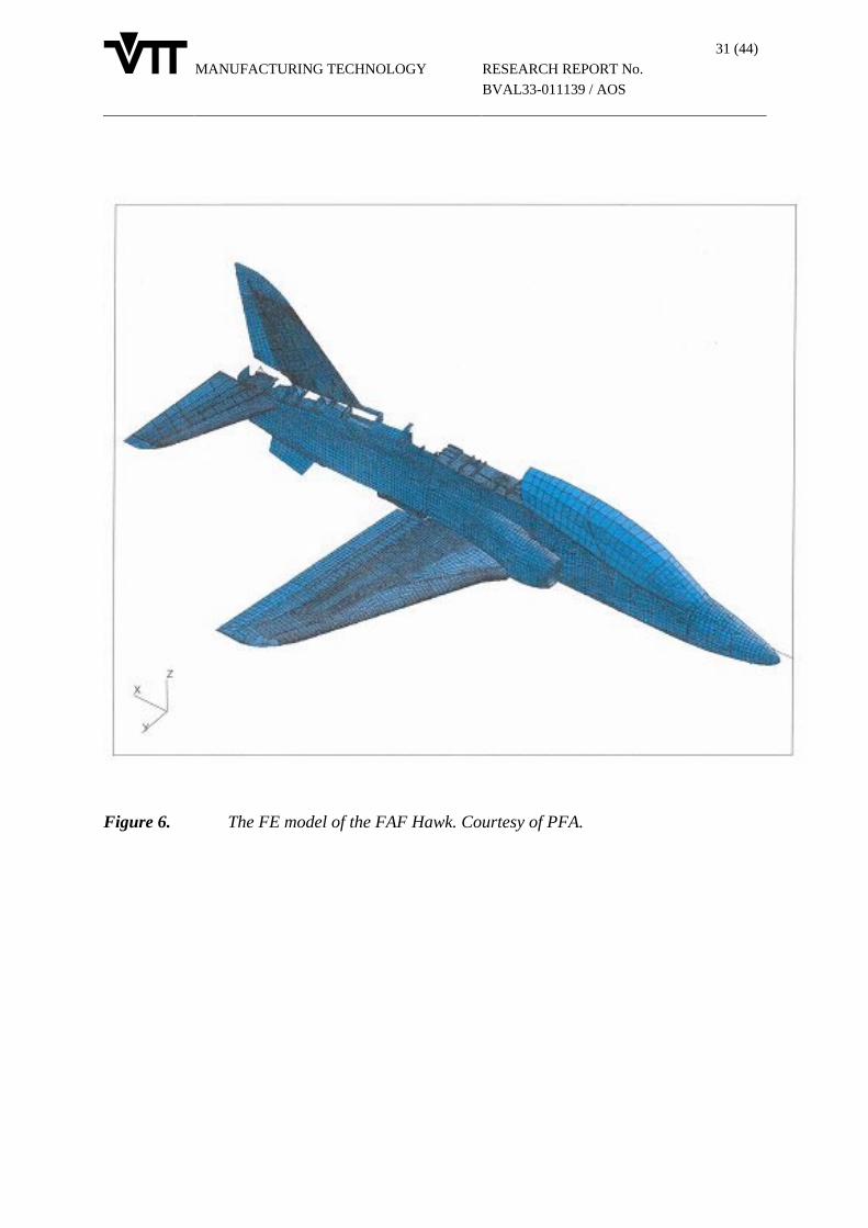
MANUFACTURING TECHNOLOGY
31 (44)
RESEARCH REPORT No.
BVAL33-011139 / AOS
Figure 6. The FE model of the FAF Hawk. Courtesy of PFA.
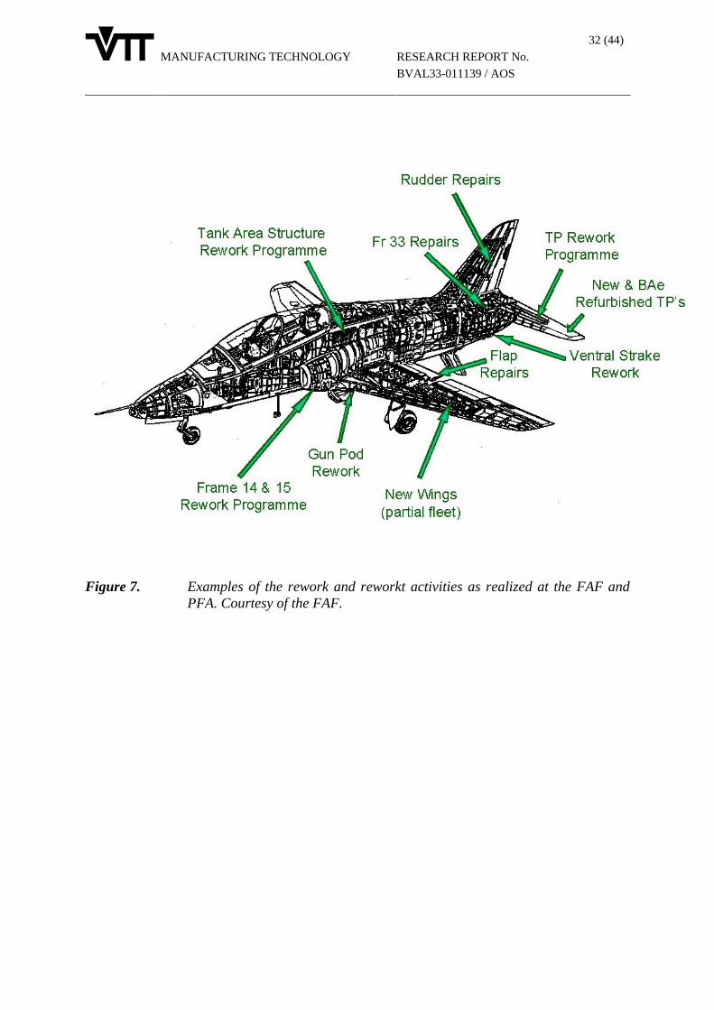
MANUFACTURING TECHNOLOGY
32 (44)
RESEARCH REPORT No.
BVAL33-011139 / AOS
Figure 7. Examples of the rework and reworkt activities as realized at the FAF andPFA. Courtesy of the FAF.
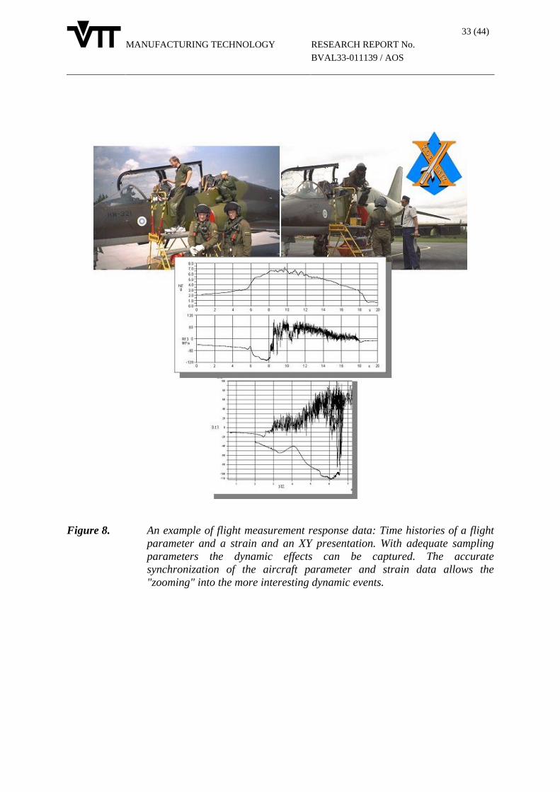
MANUFACTURING TECHNOLOGY
33 (44)
RESEARCH REPORT No.
BVAL33-011139 / AOS
Figure 8. An example of flight measurement response data: Time histories of a flightparameter and a strain and an XY presentation. With adequate samplingparameters the dynamic effects can be captured. The accuratesynchronization of the aircraft parameter and strain data allows the"zooming" into the more interesting dynamic events.

MANUFACTURING TECHNOLOGY
34 (44)
RESEARCH REPORT No.
BVAL33-011139 / AOS
Figure 9. The surface grid of a BAe Hawk Mk.51. The aileron deflection is 11.3°representing a rolling condition. Courtesy of HUT/LAT.
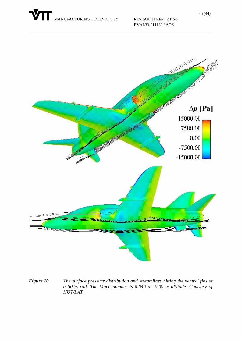
MANUFACTURING TECHNOLOGY
35 (44)
RESEARCH REPORT No.
BVAL33-011139 / AOS
Figure 10. The surface pressure distribution and streamlines hitting the ventral fins ata 50°/s roll. The Mach number is 0.646 at 2500 m altitude. Courtesy ofHUT/LAT.

MANUFACTURING TECHNOLOGY
36 (44)
RESEARCH REPORT No.
BVAL33-011139 / AOS
Figure 11. A schematic of the prestressed fastener joint (Hi-Tique) representing the finskin-to-spar joint used in the round robin analyses: The model by HUT/LLS(upper two with fasteners) and the model by VTT (lower left). Fracturesurface of a fatigue test specimen by HUT/LLS (lower right).
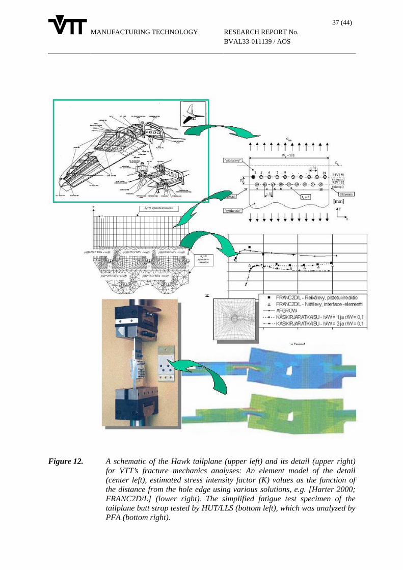
MANUFACTURING TECHNOLOGY
37 (44)
RESEARCH REPORT No.
BVAL33-011139 / AOS
Figure 12. A schematic of the Hawk tailplane (upper left) and its detail (upper right)for VTT’s fracture mechanics analyses: An element model of the detail(center left), estimated stress intensity factor (K) values as the function ofthe distance from the hole edge using various solutions, e.g. [Harter 2000;FRANC2D/L] (lower right). The simplified fatigue test specimen of thetailplane butt strap tested by HUT/LLS (bottom left), which was analyzed byPFA (bottom right).

MANUFACTURING TECHNOLOGY
38 (44)
RESEARCH REPORT No.
BVAL33-011139 / AOS
Figure 13. A scrapped center fuselage of the FAF Hawk aircraft (a) which wasemployed as the full scale test article subjected to static pressurization tests,and a schematic of its inside (b). The same test article was employed inoriginal structure evaluation (i.e. no composite reinforcement) as well aswith the composite reinforcement. An FE model of the center fuselageregion for the MSD crack growth simulations and analyses (c) andexamples of predicted crack growth rates (d).

MANUFACTURING TECHNOLOGY
39 (44)
RESEARCH REPORT No.
BVAL33-011139 / AOS
Figure 14. The simplified, small-scale specimen (design by PFA & HUT/LLS,manufactured by PFA) representing the center fuselage detail of the FAFHawk (lower left and right: instrumented by VTT prior to protection). Thespecimen was employed to study candidate composite reinforcementtechniques: Test set-up at HUT/LLS (upper left) and example of VTT’sresults (upper right).
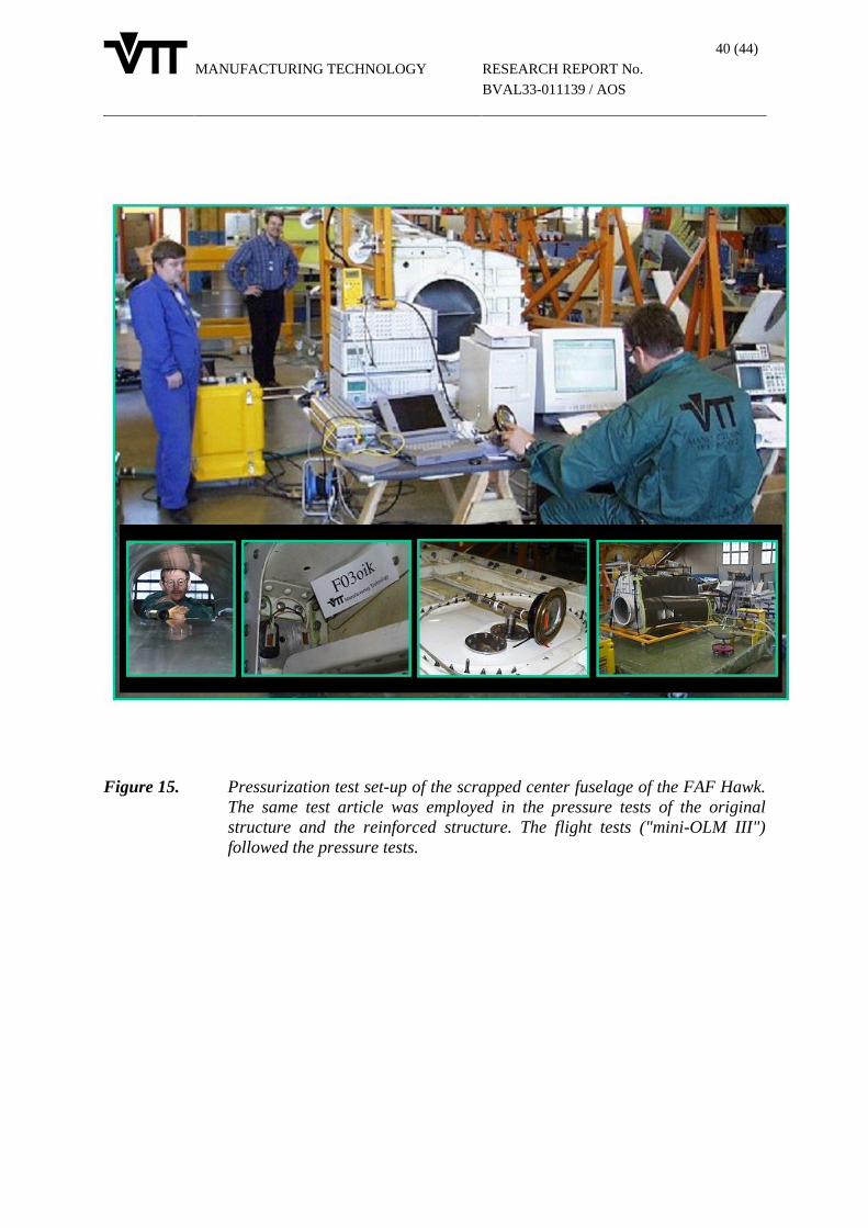
MANUFACTURING TECHNOLOGY
40 (44)
RESEARCH REPORT No.
BVAL33-011139 / AOS
Figure 15. Pressurization test set-up of the scrapped center fuselage of the FAF Hawk.The same test article was employed in the pressure tests of the originalstructure and the reinforced structure. The flight tests ("mini-OLM III")followed the pressure tests.
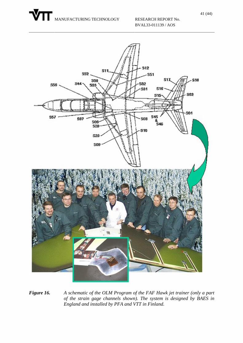
MANUFACTURING TECHNOLOGY
41 (44)
RESEARCH REPORT No.
BVAL33-011139 / AOS
Figure 16. A schematic of the OLM Program of the FAF Hawk jet trainer (only a partof the strain gage channels shown). The system is designed by BAES inEngland and installed by PFA and VTT in Finland.
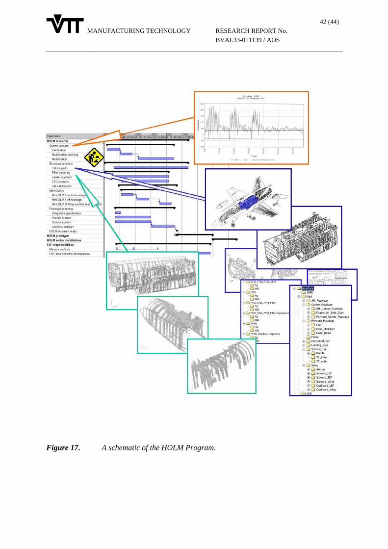
MANUFACTURING TECHNOLOGY
42 (44)
RESEARCH REPORT No.
BVAL33-011139 / AOS
Figure 17. A schematic of the HOLM Program.
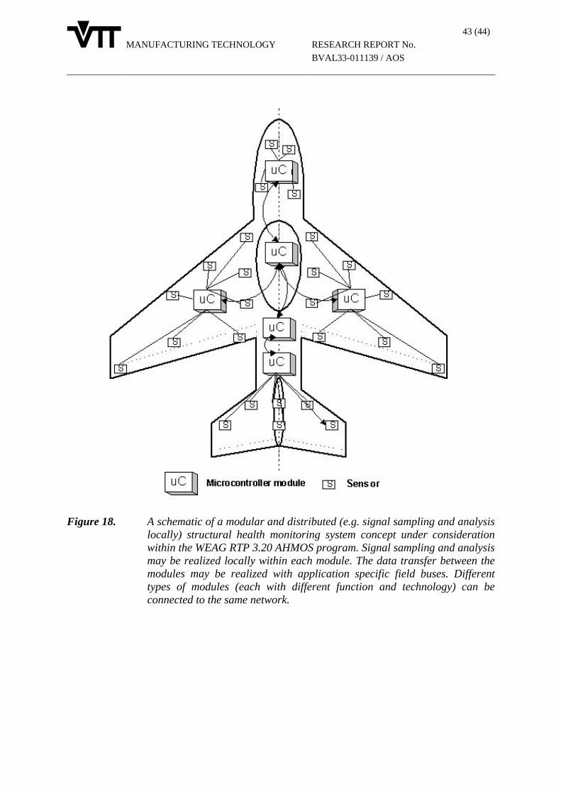
MANUFACTURING TECHNOLOGY
43 (44)
RESEARCH REPORT No.
BVAL33-011139 / AOS
Figure 18. A schematic of a modular and distributed (e.g. signal sampling and analysislocally) structural health monitoring system concept under considerationwithin the WEAG RTP 3.20 AHMOS program. Signal sampling and analysismay be realized locally within each module. The data transfer between themodules may be realized with application specific field buses. Differenttypes of modules (each with different function and technology) can beconnected to the same network.
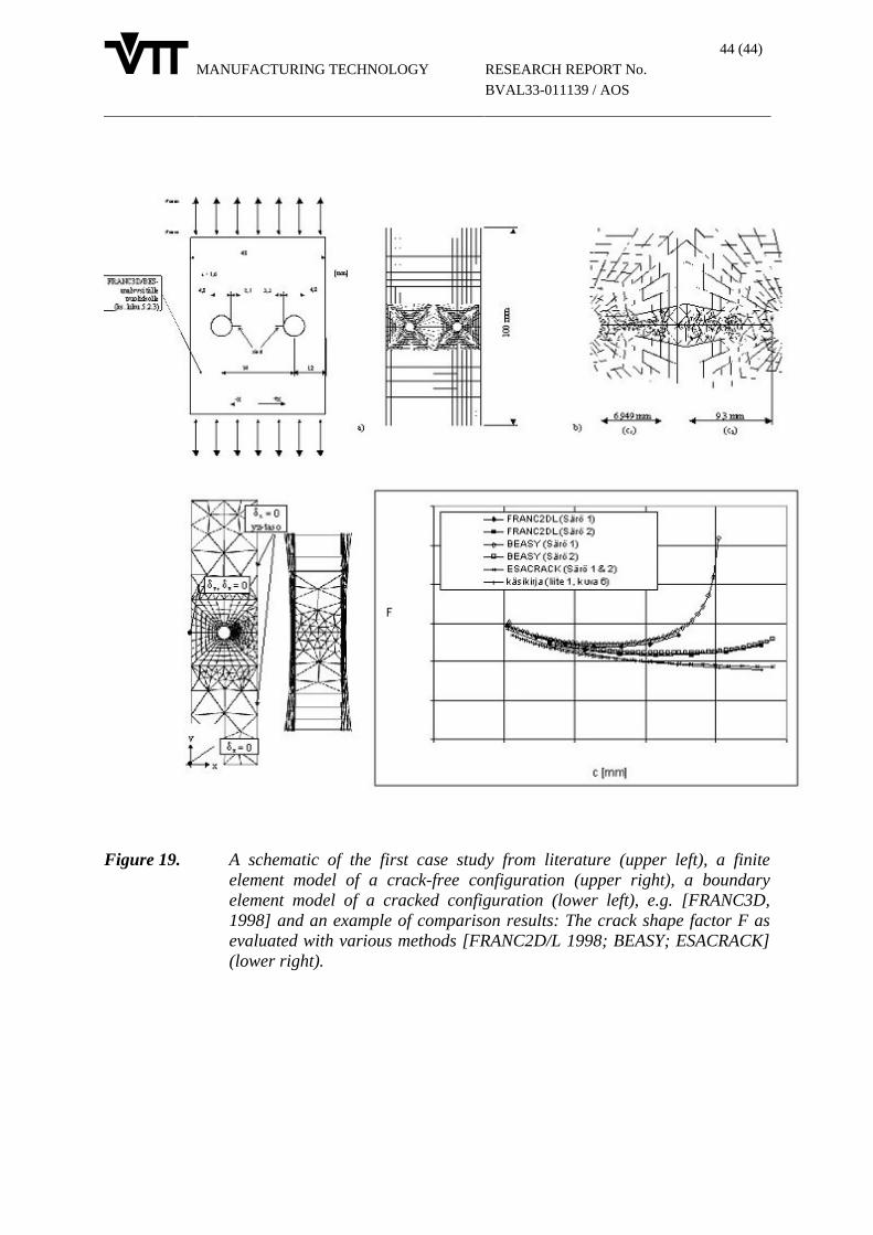
MANUFACTURING TECHNOLOGY
44 (44)
RESEARCH REPORT No.
BVAL33-011139 / AOS
Figure 19. A schematic of the first case study from literature (upper left), a finiteelement model of a crack-free configuration (upper right), a boundaryelement model of a cracked configuration (lower left), e.g. [FRANC3D,1998] and an example of comparison results: The crack shape factor F asevaluated with various methods [FRANC2D/L 1998; BEASY; ESACRACK](lower right).