Embed Size (px)
Citation preview

EUROMECH Colloquium on Scientific and Technological Challenges in Offshore Vertical Axis Wind Turbines
1
A review of state-of-the-art in torque generation and control of
floating vertical-axis wind turbines
Elin Andersen1, Uwe S. Paulsen2, Daniel Todd Griffith3, Helge Aa. Madsen2
1Department of Mechanical and Structural Engineering and Materials Science, University of Stavanger, 4036, Norway 5 2Department of Wind Energy, Technical University of Denmark, Roskilde, 4000, Denmark 3Wind Energy Technology Department, Sandia National Laboratories, Albuquerque, NM 87185, USA
Correspondence to: Uwe S. Paulsen ([email protected])
Abstract. Large-scale floating vertical axis wind turbines have great potential for offshore applications. This paper will review 10
the recent developments for generating torque and controlling vertical-axis wind turbines (VAWTs) specifically for floating
applications. The phenomena presented include dynamic stall and pitching of the blades, as well as design of airfoils for VAWT
applications.
1 Introduction
The increasing demand for renewable energy has resulted in new wind turbine systems, greater installed capacity, new designs 15
and new levels of maturity over the last three decades (Tiju et al., 2006). Wind turbine systems offer increasing reliability in
technical aspects such as lifetime and operating availability. They provide electricity from wind at a competitive cost compared
to other existing methods of energy supply. The areas available to wind farms are getting constricted, and the way the society
use wind energy is changing. As a result of this, new markets have opened. One such market is offshore wind, where new and
different concepts must be considered. 20
The vertical-axis wind turbine (VAWT) can be beneficial for floating offshore concepts, as floating VAWTs have inherent
advantages when compared to floating horizontal-axis wind turbines (HAWTs). Recently, major efforts have been undertaken
in both Europe and the United States to explore this technology. The recent study made on the offshore Deepwind VAWT
concept, a floating large-scale Troposkien-shaped Darrieus turbine, see Figure 1, used the technology for VAWTs developed 25
by Sandia between 1970 and 1995 (Ashwill and Leonard, 1986). In the Deepwind project (Paulsen et al., 2014) the previous
research was applied to a floating wind turbine. A report from Sandia reviews the development and configurations of VAWTs,
and the lessons learned (Sutherland et al., 2012).
EUROMECH Colloquium on Scientific and Technological Challenges in Offshore Vertical Axis Wind Turbines
2
The Deepwind VAWT concept is challenging existing offshore wind technology, and has drawn attention due to its new
design, well suited for offshore conditions (Paulsen et al., 2015). This project1 builds on the assumption that stall- and variable
speed control of a Troposkien shaped Darrieus rotor will be more cost efficient than a pitch controlled H-type Darrieus rotor.
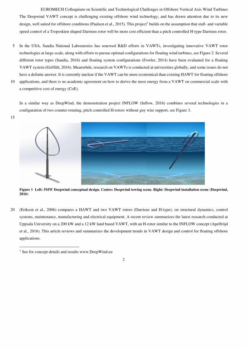
In the USA, Sandia National Laboratories has renewed R&D efforts in VAWTs, investigating innovative VAWT rotor 5
technologies at large-scale, along with efforts to pursue optimal configurations for floating wind turbines, see Figure 2. Several
different rotor types (Sandia, 2016) and floating system configurations (Fowler, 2014) have been evaluated for a floating
VAWT system (Griffith, 2016). Meanwhile, research on VAWTs is conducted at universities globally, and some issues do not
have a definite answer. It is currently unclear if the VAWT can be more economical than existing HAWT for floating offshore
applications, and there is no academic agreement on how to derive the most energy from a VAWT on commercial scale with 10
a competitive cost of energy (CoE).
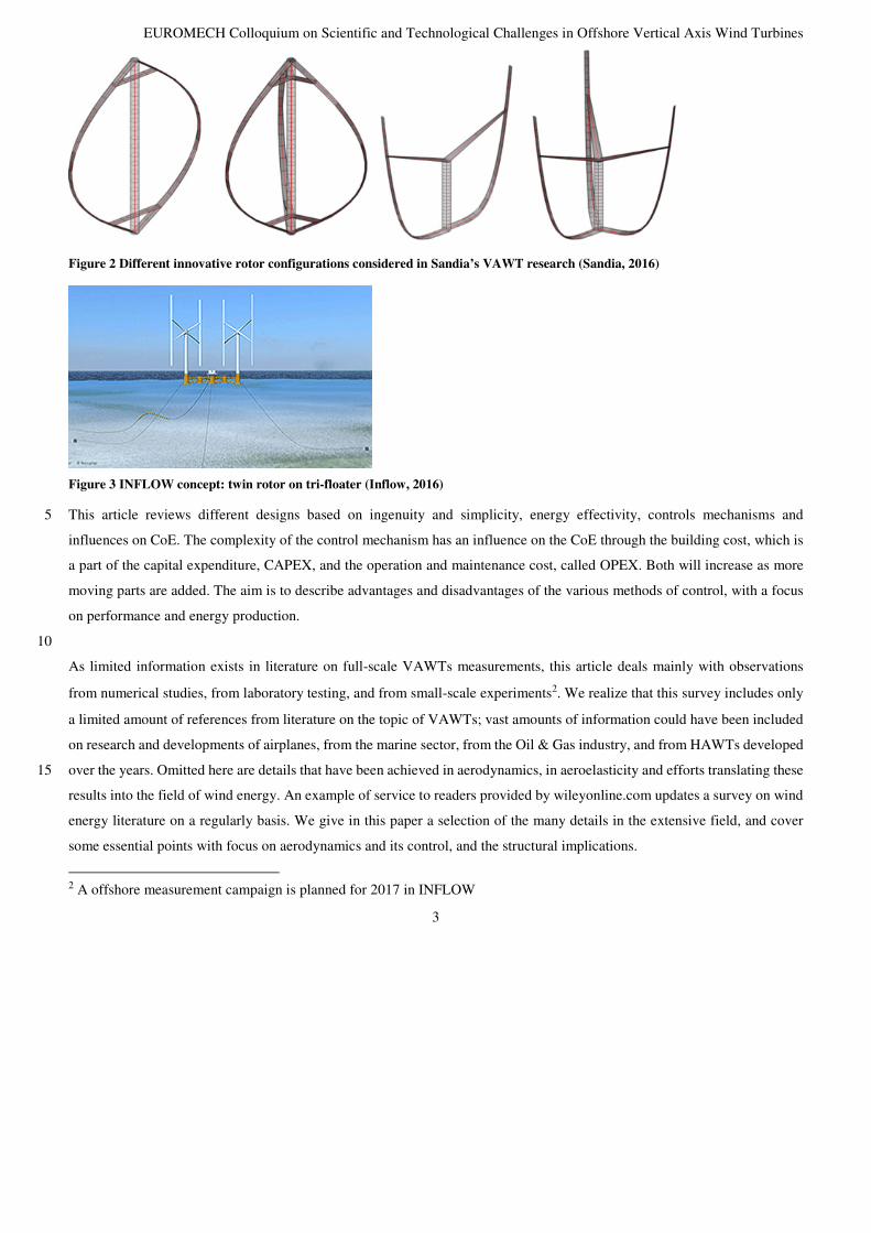
In a similar way as DeepWind, the demonstration project INFLOW (Inflow, 2016) combines several technologies in a
configuration of two counter-rotating, pitch controlled H-rotors without guy wire support, see Figure 3.
15
Figure 1 Left: 5MW Deepwind conceptual design. Centre: Deepwind towing scene. Right: Deepwind installation scene (Deepwind, 2016)
(Erikson et al., 2006) compares a HAWT and two VAWT rotors (Darrieus and H-type), on structural dynamics, control 20
systems, maintenance, manufacturing and electrical equipment. A recent review summarizes the latest research conducted at
Uppsala University on a 200 kW and a 12 kW land based VAWT, with an H-rotor similar to the INFLOW concept (Apelfröjd
et al., 2016). This article reviews and summarizes the development trends in VAWT design and control for floating offshore
applications.
1 See for concept details and results www.DeepWind.eu
EUROMECH Colloquium on Scientific and Technological Challenges in Offshore Vertical Axis Wind Turbines
3
Figure 2 Different innovative rotor configurations considered in Sandia’s VAWT research (Sandia, 2016)
Figure 3 INFLOW concept: twin rotor on tri-floater (Inflow, 2016)
This article reviews different designs based on ingenuity and simplicity, energy effectivity, controls mechanisms and 5
influences on CoE. The complexity of the control mechanism has an influence on the CoE through the building cost, which is
a part of the capital expenditure, CAPEX, and the operation and maintenance cost, called OPEX. Both will increase as more
moving parts are added. The aim is to describe advantages and disadvantages of the various methods of control, with a focus
on performance and energy production.
10
As limited information exists in literature on full-scale VAWTs measurements, this article deals mainly with observations
from numerical studies, from laboratory testing, and from small-scale experiments2. We realize that this survey includes only
a limited amount of references from literature on the topic of VAWTs; vast amounts of information could have been included
on research and developments of airplanes, from the marine sector, from the Oil & Gas industry, and from HAWTs developed
over the years. Omitted here are details that have been achieved in aerodynamics, in aeroelasticity and efforts translating these 15
results into the field of wind energy. An example of service to readers provided by wileyonline.com updates a survey on wind
energy literature on a regularly basis. We give in this paper a selection of the many details in the extensive field, and cover
some essential points with focus on aerodynamics and its control, and the structural implications.
2 A offshore measurement campaign is planned for 2017 in INFLOW

EUROMECH Colloquium on Scientific and Technological Challenges in Offshore Vertical Axis Wind Turbines
4
On controls, (Apelfröjd et al., 2016) reports on the Uppsala H-rotor with PMG generator and electronics converter. (Merz, and
Svendsen, 2013) describe the control algorithm for the DeepWind 5 MW conceptual design, and (Ritchie et al., 2016a)
summarizes the electrical aspects on generator and bearings with the overall simplicity outlined in (Paulsen et al., 2015), and
in (Ritchie et al., 2016b) on the power electronics converter. 5
On review of offshore floating wind energy, (Henderson and Witcher, 2010) elaborate on the potentials of using HAWTs with
floating support structures, hereby explaining the principles, challenges and interactions with controls advocating for careful
design of HAWT pitching mechanism. Therefore, the article addresses some common challenges for VAWTs.
2 Approaches and Methods
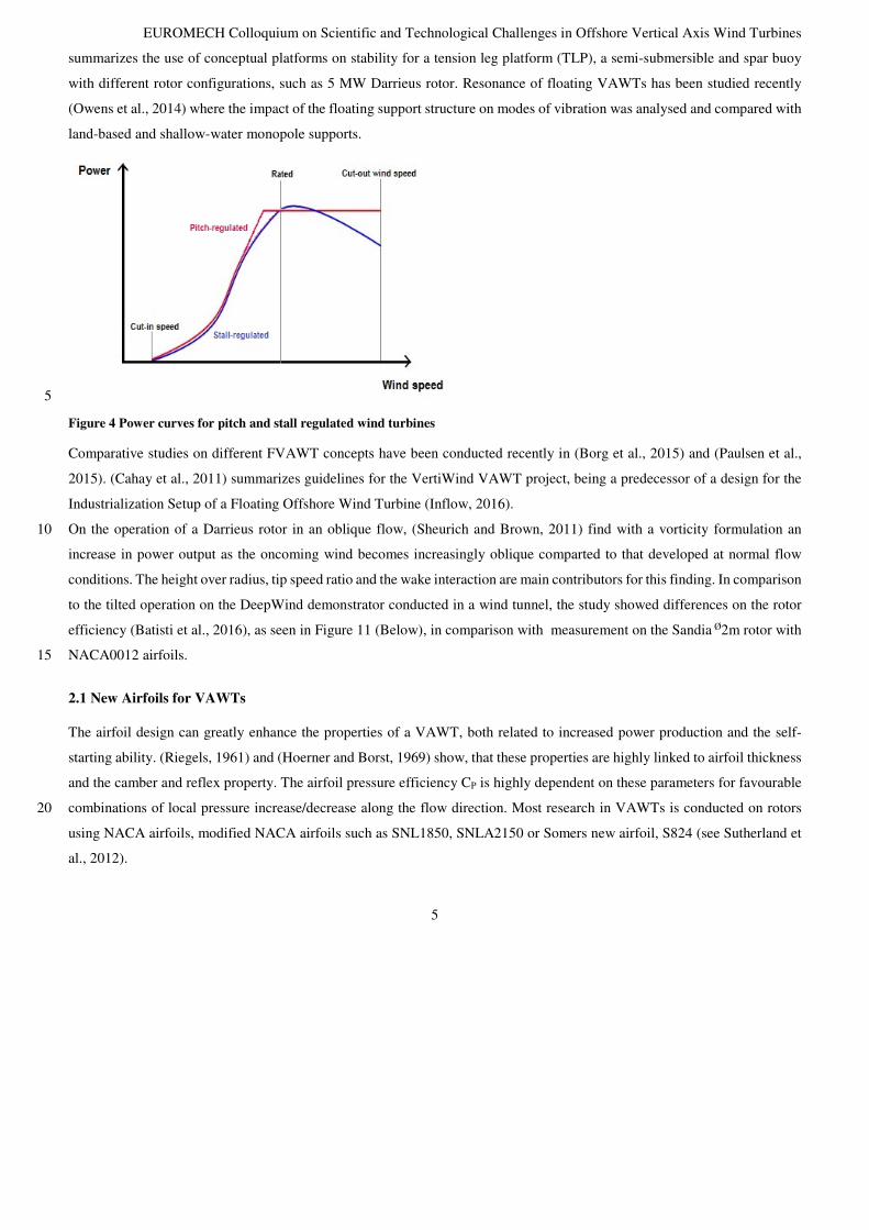
This paper will look into both pitch-regulated and stall-regulated vertical axis wind turbines. Pitch-regulated wind turbines 10
have increasing power up to the rated wind speed, and then produce constant power up to a cut-out wind speed. This is achieved
by pitching the blades along the longitudinal axis. At the cut out speed, the pitch control is usually no longer able to limit the
rotational speed, unless pitching increases the rotor drag. At these high wind speeds, the structural integrity of the turbine can
also be threatened by vibration, turbulence or gusts.
The blades, and in particular the airfoils, of a stall-regulated wind turbine are designed for constant tip speed ratio λ=ωR/U∞ 15
in such a way that the rotational speed decreases for wind speed above a certain value, where power is limited onwards. The
control is by far non-trivial to make the design protect the wind turbine from over-speeding. A reduced rotational speed leads
to a decrease in power production. As the angle of attack continues to increase above a limit, stalling occurs, and the area of
the blades that stalls propagates outwards onto larger parts of the blade.
The main difference between pitch-regulated and stall-regulated wind turbines is at high wind speeds, where the pitch turbines 20
can have a constant power production, while the stall-regulated turbines decrease power in dependency on rpm, see Figure 4.
It is obvious, that curved blades are impracticable for using existing technical pitching devices. Both pitch-regulated and stall-
regulated turbines have devices (e.g. spoiler, water brake, see (Paulsen et al.,2014)) that can keep the turbine still or in safe,
slow motion at very high wind speeds, above cut-out speed.
Five different aspects of control of VAWTs will be assessed in this review: airfoil design, the dynamic stall phenomenon, 25
active & passive pitching of the blades, and braking (parking) strategies for VAWTs. A VAWT has three main phases of
operation: starting up and operation below and above rated wind speed, and the aspects of control will be evaluated in these
phases. (Borg et al., 2014) gives a survey of the VAWTs in comparison with HAWTs in key topics such as technology,
conversion efficiency, upscaling, fatigue, and machinery position. (Wang, 2013) gives a dynamic model of a 2-bladed 5MW
Darrieus type turbine integrated with the OC4 DeepCwind semi-submersible support structure in a model-to-model 30
comparison. The 2p response and first natural pitch motion from wind can be observed when the wind is combined with wave.
(Cheng et al., 2015) makes a review on trends and technologies in floating vertical axis wind turbines (FVAWTs) and
EUROMECH Colloquium on Scientific and Technological Challenges in Offshore Vertical Axis Wind Turbines
5
summarizes the use of conceptual platforms on stability for a tension leg platform (TLP), a semi-submersible and spar buoy
with different rotor configurations, such as 5 MW Darrieus rotor. Resonance of floating VAWTs has been studied recently
(Owens et al., 2014) where the impact of the floating support structure on modes of vibration was analysed and compared with
land-based and shallow-water monopole supports.
5
Figure 4 Power curves for pitch and stall regulated wind turbines
Comparative studies on different FVAWT concepts have been conducted recently in (Borg et al., 2015) and (Paulsen et al.,
2015). (Cahay et al., 2011) summarizes guidelines for the VertiWind VAWT project, being a predecessor of a design for the
Industrialization Setup of a Floating Offshore Wind Turbine (Inflow, 2016).
On the operation of a Darrieus rotor in an oblique flow, (Sheurich and Brown, 2011) find with a vorticity formulation an 10
increase in power output as the oncoming wind becomes increasingly oblique comparted to that developed at normal flow
conditions. The height over radius, tip speed ratio and the wake interaction are main contributors for this finding. In comparison
to the tilted operation on the DeepWind demonstrator conducted in a wind tunnel, the study showed differences on the rotor
efficiency (Batisti et al., 2016), as seen in Figure 11 (Below), in comparison with measurement on the Sandia Ø2m rotor with
NACA0012 airfoils. 15
2.1 New Airfoils for VAWTs
The airfoil design can greatly enhance the properties of a VAWT, both related to increased power production and the self-
starting ability. (Riegels, 1961) and (Hoerner and Borst, 1969) show, that these properties are highly linked to airfoil thickness
and the camber and reflex property. The airfoil pressure efficiency CP is highly dependent on these parameters for favourable
combinations of local pressure increase/decrease along the flow direction. Most research in VAWTs is conducted on rotors 20
using NACA airfoils, modified NACA airfoils such as SNL1850, SNLA2150 or Somers new airfoil, S824 (see Sutherland et
al., 2012).
EUROMECH Colloquium on Scientific and Technological Challenges in Offshore Vertical Axis Wind Turbines
6
TUDelft developed tailored airfoils for DeepWind (DU12W262). It is chambered with reflex properties of the trailing edge
that gives a steeper CL curve than a similar NACA airfoil. TU Delft has also done research on thick airfoils (DUyyWxxx),
where airfoil design methodology is explained (Timmer and van Rooij, 2003). The DU96 profile was originally intended as
an airfoil section with position close to the tip of HAWTs. The performance of the designed airfoil has been tested for a range
of Reynolds numbers of the order of 0.7 to 1 million, relevant for small to medium sized wind-energy applications. 5
(Beri and Yao, 2011a) did a study on a Darrieus rotor with asymmetric blades using the NACA 2415 airfoil. Their analysis
concluded that a chambered airfoil can have enhanced start-up capabilities, but that there are losses due to lower performance
at higher λ. The same authors then showed that a modified NACA0018 airfoil with a hinged tail would have better self-starting
performance than the NACA2415 (Beri and Yao, 2011b). (Takao et al., 2007) and (Kuma et al., 2007) show that directed guide
vanes can be an advantage in straight bladed Darrieus VAWTs, then (Takao et al., 2009) conducts an experimental study of 10
the effect of guide vanes. This study shows that the power coefficient and the torque coefficient are independent of the number
of guide vanes. Chambered airfoils can make the turbine self-starting and increase the power production below rated.
Several airfoil designs for VAWTs have been evaluated over the past decades, and technology developed for aircrafts could
serve as inspiration for transfer of technology into VAWTs. Classic design guide lines for the NACA-airfoils3, can be found 15
in (Hoerner, 1975), (Riegels, 1961), NACA bulletins (e.g. 3007 (Kelly and Hayter, 1953)), and modern textbooks. Sandia-
airfoils, chambered airfoils from TU Delft: DUyyWxxx, the RISØ4, FFA, NREL and various symmetrical airfoils information
are found in different reports from the parent organisations. Studies for achieving maximum lift for airplanes: (Hoerner and
Borst, 1969) and the NACA TN 3007 report (Kelly and Heyter, 1953) show that maximum lift can be considerably increased
by the use of a nose flap for profiles, where the point of turbulent separation is located closely behind the profile nose (Krüger, 20
1947). However, the stalling characteristics are very important to target when designing airfoils for VAWTs.
2.2 Dynamic stall
The observation of edgewise oscillations, instabilities or vibrations on modern HAWTs and later VAWTs were under extensive
investigations by Sandia (see for a list of references (Sutherland et al., 2012). This encouraged the community to try to
understand the physics behind dynamic stall, starting with studies on wings undergoing aircraft flutter (controlled aerodynamic 25
instability phenomenon), treated for damped or divergent motion in (Theodorsen, 1935) for oscillating or heaving wing
sections. Theodorsen set up a 2 DOF system in non-stationary potential flow, with vortex flow acting at the trailing edge under
Kutta condition at low angle of attacks. The results were pressure forces on the suction and pressure side of the airfoil, inducing
small oscillatory excursions about a position of equilibrium. The classical flutter is applicable to 2D airfoil conditions, with
3 NACA-airfoils were used in wing design of airplanes, and they are widely used as airfoil properties reference. 4 Particular airfoil types have been designed for wind turbine rotors, type A,B,C,P type, see (Fuglsang P and Bak C, 2004), (Bak et al,2006), ( Bak et al, 2008) and (Bak et al, 2004)
EUROMECH Colloquium on Scientific and Technological Challenges in Offshore Vertical Axis Wind Turbines
7
lift coefficient CL=2πα providing a response 2παF(k), where F is a complex function and k is the reduced frequency. This
linear theory is valid only for non-stalled conditions for VAWTs. (Yusuf Billah and Scanlan, 1991) explains the self-oscillatory
motions using the example of the Tahomay Narrows bridge disaster in 1940, eradicating misconceptions between the
aerodynamically induced condition of self-excitation in a torsional degree of freedom and the «elementary forced resonance
of a mechanical oscillator». The disaster has served as motivation for studying vortex separation on bluff, square and 5
rectangular cross-sections. (Hansen, 2007a) and (Hansen, 2007b) studied the physical phenomena related to stall-induced
vibrations. (Skrzypiński et al., 2013) studied this for horizontal wind turbine blades at standstill, and this reference should be
applicable on VAWT with high angles of attack during normal operation (Skrzypiński and Gaunaa, 2014). (Skrzypiński and
Gaunaa, 2014) describe improved sub-models for the wind turbine blade vibration problem for aeroelastic computational tools.
These are usually called dynamic stall models. The paper also includes the model from (Leishman and Beddoes, 1986). Every 10
airfoil has a point where the pressure generated by the circulation around the airfoil causes the flow to detach. At this point,
the increase in lift force halts, and the drag force increase. But the transition from one state to the other cannot be instantaneous,
and trailing edge stall emerge. A sub-model for trailing edge stall for HAWTs is incorporated adequately by (Leishman and
Beddoes, 1986). An unpublished report (Pirrung et al., 2016) investigates the applicability for of this model for VAWTs, and
recommends a modification of the instantaneous lift coefficient due to the circular motion of VAWT blades. In the case of 15
normal operating HAWTs, (Bak et al., 1999) studied the particular double stall phenomena. These phenomena were observed
during power performance measurements on HAWTs as far back the mid-80´s. The double stall has a massive, undesirable
effect on the determination of maximum loads, due to an observed instant shift from one load level to another. (Bak et al.,
1999) combines literature survey, wind tunnel study, and CFD simulations to determine the origin and effect of leading edge
stall, specifically on NACA 63 -2nn and RISØ airfoils4. The wind tunnel study on a NACA 63 -2nn blade showed clear distinct 20
levels of stall on a non-tapered airfoil, very similar to stalling patterns known from airplanes (Hoerner and Boerst, 1969). High
drag level occurred when low lift was observed and low drag level emerged when high lift was present. From experiments,
(Madsen, 1999) concludes that zigzag tape of various roughness applied on the leading edge eradicates double stall on NACA
63-215. Another conclusion is that double stall on airplane airfoils appears as leading-edge stall, trailing-edge stall or a
combination depending on the thickness of the airfoils. Important parameters affecting maximum lift are Reynolds number, 25
airfoil shape and turbulence. CFD investigation on NACA 63-215 and RISØ airfoil4 for fully turbulent and transitional flow
were made, and computational results from transitional flow agrees well with measurements of leading edge stall. (Madsen,
1999) further stated from known literature: i) a highly cambered or thicker airfoil section does not present difficulties to the
flow around a well-rounded leading edge, and ii) CFD results supports this conclusion. Furthermore, iii) double stall is closely
related to the actual geometry of the leading edge of the airfoil. Then, iv) an airfoil subjected to a change of surface roughness 30
from rain or bugs can avoid double stall, and that v) double stall probably can be avoided with new airfoils design.
(Castelein et al., 2015) reports on an experimental wind tunnel facility situated at TUDelft, and measures dynamic stall with
the particle image velocimetry (PIV) method on a rotating Ø0.5m H-rotor. This can be used experimentally to benchmark

EUROMECH Colloquium on Scientific and Technological Challenges in Offshore Vertical Axis Wind Turbines
8
rotors in dynamic stall conditions around λ~4.5. However, the small rotor size leads to an expected discrepancy due to the
Reynolds number effects, in the order of 102-103 in comparison with a MW full-scale rotor. In absence of full-scale
experiments, previous works on VAWTs (Nobile et al., 2011), (Dyachuk and Goude, 2015) deal with applying computational
methods for predicting dynamic stall (elaboration of principal stages of leading edge originating dynamic stall, λ<4) and often
comparing with available references, in particular with experimental results obtained by Sandia (Sutherland et al., 2012). 5
(Dunne, 2016) conducted a PIV study in a water tunnel on dynamic stall of a NACA0018 airfoil, undergoing various unsteady
motions at k~0.12, showed flow behavior associated with the driving pitch/surge frequency for leading edge vertical structure.
A secondary separation mode, twice the pitch/surge frequency, shows an anti-spinning vortex system reattaching effect for
nose down pitching. The results, obtained at Reynolds numbers of about 105, shows similarities prior to stall, also observed in
experiments carried out at TUDelft (Simão Fereira et al., 2009). Full-scale VAWT flow effects incorporate Coriolis terms, 10
while laboratory experiments are conducted with pitching/surging blade in a uniform onset. However, Coriolis effects on the
boundary layer and double stall during these laboratory tests using NACA airfoils seems not to be observed. Literature on
other tests for studying double stall on VAWTs at high Reynolds number is not known to the authors.
The above information applies as general cases to the conditions of a blade or airfoil pitching around a central axis. 15
Darrieus turbines with fixed blades are characterized by low, or even negative torque, at tip speed ratios λ below that at which
they are designed to run (λ< ~3). This means that they have a difficulty self-starting and need grid supply that can drive the
turbines to speed when enough wind is measured. In turbulent wind, this low torque inhibits their energy capture. Particular
airfoil chamber and reflex design offers ways to enhance self-starting, because of their high influence on maximum lift and
stall capability. 20
One control method described in this paper is the passive control by dynamic stall. A VAWT has an inherent unsteady
aerodynamic behavior due to the variation in angle of attack with the angle of rotation, and the experienced velocity and
Reynolds number. Therefore, dynamic stall is an intrinsic part of the operation of a VAWT at low λ, and it has a significant
impact on both loads and power (Oler et al., 1983). The dynamic stall phenomenon can both inhibit self-starting and keep the 25
turbine from over-speeding at wind speeds above rated.
The peak power is attained in a small range of wind speeds, though the turbine drive train and generator must be sized to accept
the maximum power output in a safe way. Therefore, a reduction of the rated wind speed compared to a turbine operating
without upper power limit is economically favourable (the reduction will influence the set point of the lower cut-out wind 30
speed). Since the wind is infrequent in the range above the regulation wind speed, the net loss of produced power is relatively
small. It therefore allows the use of smaller, less costly equipment (Oler et al, 1983). Additionally this feature enhances safety
issues concerned with start-up at high wind speed.
EUROMECH Colloquium on Scientific and Technological Challenges in Offshore Vertical Axis Wind Turbines
9
Development in modern HAWTs has shown it is possible to modify stall properties using stall strips (Thistrup Pedersen et al.,
1998). Stall strips are triangular shaped devices attached to the leading edge of an airfoil. The purpose of the strips is to initiate
flow separation.
HAWT rotor developments have also shown that vortex generators (VG) are an effective way to impact the stall properties of
an airfoil. A VG is a small vane attached to the lifting side of the turbine blade, usually in the height order of the boundary 5
layer. The effect of VG is to delay dynamic stalling, and local flow separation. VGs generate vortices that energize the
boundary layer making it more resistant to separation and subsequent stalling.
2.3 Pitching blades
Straight-bladed H-rotors have two more options for control: the active and passive pitching of the blades. By pitching the
blades in a cyclic (and blade independent) way, it is possible to increase the time that an airfoil produces lift. This gives an 10
overall increase in power production below rated wind speed but at the expense of the turbine being independent on wind
direction. Pitching can also be used to control the power output at rated wind speed, and avoid over-speeding when the wind
is gusty. When the turbine experience wind speeds above rated power, blades can pitch so that there is less lift and more drag.
This effect is due to increasing flow separation along the blade length (blades are pitched into stall). In a reverse controlled
process, loads and power can be reduced by pitching towards lesser angle of attack. 15
In the report of (Fanucci and Walters, 1979) they evaluate the potential of a circulation controlled vertical axis wind turbine
with straight blades for being able to facilitate boundary layer control (by blowing) and cyclic pitching of the blades hereby
increasing the efficiency of the rotor.
A number of researchers have demonstrated that the provision of variable-pitch blades will make the Darrieus turbines self-20
starting. For instance, it has been shown that if the blade pitch angle is varied as a sinusoidal function of the azimuth angle, in
phase with the variation of the angle of attack, the amplitude of the angle of attack variation experienced by the blade can be
reduced (Pawsey, 2003).
EUROMECH Colloquium on Scientific and Technological Challenges in Offshore Vertical Axis Wind Turbines
10
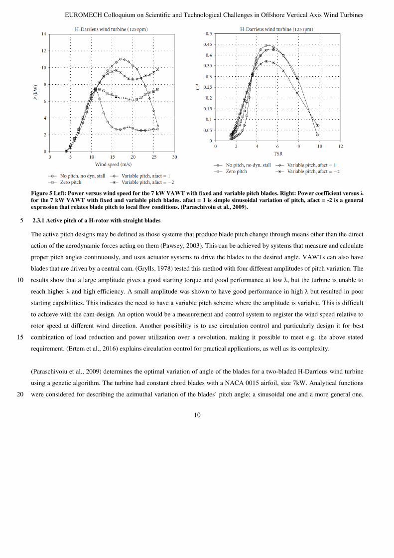
Figure 5 Left: Power versus wind speed for the 7 kW VAWT with fixed and variable pitch blades. Right: Power coefficient versus λ for the 7 kW VAWT with fixed and variable pitch blades. afact = 1 is simple sinusoidal variation of pitch, afact = -2 is a general expression that relates blade pitch to local flow conditions. (Paraschivoiu et al., 2009).
2.3.1 Active pitch of a H-rotor with straight blades 5
The active pitch designs may be defined as those systems that produce blade pitch change through means other than the direct
action of the aerodynamic forces acting on them (Pawsey, 2003). This can be achieved by systems that measure and calculate
proper pitch angles continuously, and uses actuator systems to drive the blades to the desired angle. VAWTs can also have
blades that are driven by a central cam. (Grylls, 1978) tested this method with four different amplitudes of pitch variation. The
results show that a large amplitude gives a good starting torque and good performance at low λ, but the turbine is unable to 10
reach higher λ and high efficiency. A small amplitude was shown to have good performance in high λ but resulted in poor
starting capabilities. This indicates the need to have a variable pitch scheme where the amplitude is variable. This is difficult
to achieve with the cam-design. An option would be a measurement and control system to register the wind speed relative to
rotor speed at different wind direction. Another possibility is to use circulation control and particularly design it for best
combination of load reduction and power utilization over a revolution, making it possible to meet e.g. the above stated 15
requirement. (Ertem et al., 2016) explains circulation control for practical applications, as well as its complexity.
(Paraschivoiu et al., 2009) determines the optimal variation of angle of the blades for a two-bladed H-Darrieus wind turbine
using a genetic algorithm. The turbine had constant chord blades with a NACA 0015 airfoil, size 7kW. Analytical functions
were considered for describing the azimuthal variation of the blades’ pitch angle; a sinusoidal one and a more general one. 20

EUROMECH Colloquium on Scientific and Technological Challenges in Offshore Vertical Axis Wind Turbines
11
When the pitch is optimized towards the lower wind speeds, it returns a gain of almost 30% in annual energy production with
a polynomial optimal pitch control. The paper regards the “variable pitch” as a viable solution to the alleviation of the negative
effects of dynamic stall, which is efficiency loss and vibrations, as well as an improvement in the rotors self-starting capabilities
and torque ripple smoothing (Hwang et al., 2006), (Kirke, 1998), (Pawsey, 2002). The 30% increase in annual production
might justify the supplementary costs related to the implementation of the variable pitch system, see Figure 5 Paraschivoiu et 5
al., 2009). (Jain and Abhishek, 2016) concludes that the amplitude of sinusoidal blade pitching must be varied with the wind
speed and λ to maximize the power output. For λ < 0.5, high amplitudes (~35°) works better, while for λ > 2.0, the pitch
amplitude should be reduced to around 10°.
2.3.2 Passive variable-pitch of a H-rotor with straight blades
The problem of achieving a decreasing pitching of the blades with increasing λ, as well as the need for a measurement and 10
control system is the main arguments for a passive variable-pitch system. Here, the pitching is determined directly by the wind
forces acting on the blade. The blade is free to pitch along a spanwise, longitudinal, axis near the leading edge. The aim is to
point into the apparent wind. (Bayly and Kentfield, 1981) and (Kirke and Lazauskas, 1993) shows that two different passive
variable-pitch VAWTs can achieve self-starting using what is called an inertial type of pitch control. The design by Kirke and
Lazauskas has a threshold that must be exceeded by the aerodynamic moment on the blade before any pitching will occur. 15
This prevents small oscillations, and lets the turbine operate as a standard fixed-blade Darrieus turbine at high λ. However, an
impact each time the blade passes zero pitch position must be handled. Kirke built and tested a turbine of 6 m diameter, and
even though some discrepancies were found between measured and predicted results, it proved to achieve self-starting and
gave more credibility to the inertial type pitch control.
2.4 Loading 20
The choice between straight or curved blades is likely to be determined mostly by structural considerations, as centrifugal
loading of straight blades are more costly than using lesser aerodynamically efficient blade airfoil sections. As shown in various
references for VAWTs (see for example Sutherland et al., 2012) and demonstrated particularly on the 34m Sandia rotor, see
(Sutherland et al., 2012) both pitch and non-pitched VAWTs generates cyclic loads occurring in the central column connecting
the blades. For a 2-bladed turbine, large cyclic drag and side-forces will occur at two cyclic peaks per revolution in the tower 25
base and contributing to fatigue of the column. A 3-bladed rotor will average the load peaks over the rotor revolution cycle
more evenly than a 2-bladed. The aerodynamic torque generated by a 2-bladed rotor is near zero when the blades are moving
directly up- and down-wind, and reaches a maximum at one-quarter revolution from this position. Thus, the main component
of torque ripple occurs at a frequency twice the rotational frequency, when the blades remain largely un-stalled. Its half-
amplitude is roughly 100% of the mean torque (Templin and South, 1976). Pitching will provide a more even load scheme 30
over the cycle, by lowering the load in the first part, then increasing it in the last part.

EUROMECH Colloquium on Scientific and Technological Challenges in Offshore Vertical Axis Wind Turbines
12
Aeroelastic instabilities originating from flow adding energy into the structure (negative damping effect) are sources of
unwanted excessive vibrations and fatigue, as shown in (Verelst et al., 2014), in (Galinos et al., 2016) for an onshore Deepwind
concept, and in (Meyer, 2016) on simulation results of the structural modified design - compared to the original DeepWind
design. In this study, edgewise instabilities observed during operation for the original design were remedied by changing 5
structural stiffnesses in blades and tower without changing weight more than 10%, and modification of the generator controls
and floater length, though edgewise vibrations persisted during standstill. Classical flutter aeroelastic instability has been
addressed for large-scale VAWTs in recent work at Sandia (Owens and Griffith, 2014). In this study, flutter margins for
different rotor types including Darrieus and V-VAWT rotors were analysed for rotors composed of both glass and carbon
materials. 10
2.5 Braking Strategies
Mechanical and aerodynamic braking are required in wind turbines to avoid over-speeding and for bringing the rotor to rest
above the cut-out speed and below the cut-in speed. Mechanical braking is provided by mechanical disc brakes, or similar. In
VAWTs, although mechanical brake requirements may be larger than for HAWTs, mechanical brake requirements may be
reduced through stall control and generator torque, as touched upon above. Aerodynamic braking, on the other hand, can be 15
provided by blade pitch, which is standard in horizontal axis wind turbines (HAWTs); and this approach is utilized in several
VAWT designs although it is only applied in the case of straight bladed H-VAWT configurations. For the case of other VAWT
rotor types, such as Darrieus rotors, aerodynamic braking, and braking in general, is more complicated. This leads to larger
and/or redundant braking systems and also to consideration of novel braking strategies. As an example of a novel braking
strategy considered for VAWTs, in a series of prior Sandia studies, a “pumped spoiling” approach was investigated wherein a 20
large number of small holes were drilled in to the upper and lower surfaces of the VAWT blade near the equator (Klimas and
Sladky, 1985a) (Klimas and Sladky, 1985b). The air volume through the carefully designed hole placements was controlled
to achieve rotor load reductions, which was demonstrated for the Sandia 5-m VAWT.
3 Results
3.1 Airfoils for VAWTs 25
Sandia has developed a tailored airfoil SNLA1850 for their VAWTs, and by FloWind Corp. on SNLA2150 and S8245 for
better performance of the FloWind 19m rotor. These airfoils have a sharp leading edge, which makes them suitable for higher
λ. The root sections of a phi-rotor experiences higher angle of attack, so the rounded leading edge of a standard NACA airfoil
5 http://www.airfoils.com/index.htm, accessed 17-08-2016
EUROMECH Colloquium on Scientific and Technological Challenges in Offshore Vertical Axis Wind Turbines
13
performs better. The tailored airfoil exhibits more reliable turbine operation via better λ range cut-off near the peak CP condition
over the standard NACA 4-series, and is implemented on a 3-bladed DeepWind turbine, see below. The Deepwind project
used symmetric common reference NACA airfoils for designing the reference 5 MW wind turbine concept, but there was an
intention to experiment with the chamber/reflex airfoils from TU Delft. This would most likely increase the energy production
of the Deepwind rotor. The airfoil tailored to a specific section of a blade serves two purposes: Structural strength and 5
aerodynamic performance. Different propelling forces between the root and equator section would cause localized edgewise
bending on a blade of a uniform dimension from the root to the equator section. This edgewise bending is insignificant for
small scale rotor, but for large scale rotors it would be detrimental. Thus, in order to minimize the fatigue, the airfoil chord
dimension was altered, so that the propelling force would be more uniform from the root to the equator. Also, the chord of the
root section was made thicker for the same purpose of reducing fatigue due to bending, and also compensate for lower λ and 10
higher angles of attack.
In the actual case, DU12W262 airfoil shape is the result of an optimization for aerodynamic and structural performance (Ragni
et al, 2014). Selected from an initial population of airfoils through a genetic algorithm, the shape was evaluated via two
objective functions. The optimization algorithm used was first presented and further discussed in (Simão Ferreira and Geurts,
2013). The structural objective function was defined as the bending stiffness in flap-wise direction of the airfoil per wall-15
thickness, in reference to the centroid of the airfoil. The aerodynamic function was based on a determined range and distribution
of angles of attack over the turbine revolution. The range of angles of attack would vary for different tip-speed ratios and
different values of 3c/2R (assuming rigid, fixed pitch blades); for the present case, a single evaluation interval of angles of
attack (∆α =14º) was accounted for in a range of possible angles of attack -20º<α<20º. The function was based on the angles
of attack distribution described in (Simão Ferreira and Geurts, 2013). Any variation of dynamic pressure with the azimuthal 20
position was not taken into account, due to the relatively lower impact shown in a secondary analysis, where it was found that
the dynamic pressure variations mostly average out across leeward and windward regions. The optimized airfoil generation
produces geometrical shapes with a wide range of thickness, among which the one with t/c = 26.2% was chosen. The resulting
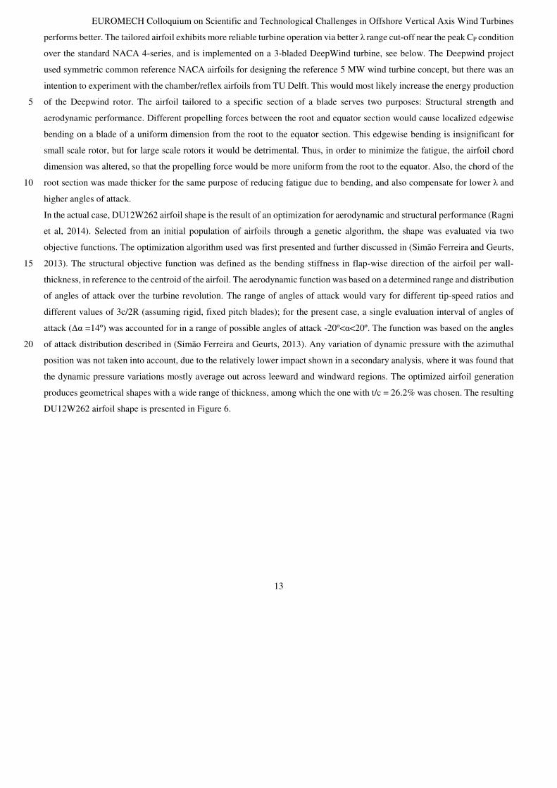
DU12W262 airfoil shape is presented in Figure 6.

EUROMECH Colloquium on Scientific and Technological Challenges in Offshore Vertical Axis Wind Turbines
14
Figure 6 DU12W262 airfoil geometry (Ragni et al., 2014)
The DU12W262 airfoil shape has been tested on a model of chord c=0.25m, span s=1.25m, aspect ratio AR=s/c=5 and
thickness t/c=26.2%. The model has been vertically installed in the closed-circuit low-turbulence wind tunnel (LTT) of the TU
Delft laboratories, in an octagonal test section 1.80m wide, 1.25m high and 2.60m long, resulting in a blockage ratio from 5
3.6% to 4.7% in the range from -20 to 20 degrees angles of attack. The pressure computation, see Figure 7, for Reynolds
1.0×10⁶ shows the evolution of the pressure coefficient along the suction and pressure side, in comparison with data reproduced
from XFOIL computations. Despite the effect of the laminar separation bubble, a good agreement is found a part from the
closest region near the leading edge at +5 degrees angle of attack, where the PIV underestimates the peak suction pressure.
Further investigation is left to elucidate the role of the laminar bubble in the airfoil optimization procedure. It is supposed that 10
the laminar separation bubble will allow for the wide drag bucket and thus the high lift-slope. In particular, it has been
confirmed that the location of the laminar bubble does not vary significantly with angle of attack.
Figure 7 Pressure coefficient distribution for top (T) and bottom (B) airfoil surfaces (S), results from PIV integrated pressure, XFOIL. Angles of attack (from left to right) -5, 0, +5 degrees, Re=1.0 ×10⁶ (Ragni et al., 2014) 15
The variability of the airfoil performance with different Reynolds numbers has been investigated in more detail by use of the
wind-tunnel wall-pressure sensors. Figure 8 presents the airfoil lift coefficients for different Reynolds numbers, in both free
(left) and forced boundary layer transition (right) configurations as obtained from integration of the wind-tunnel wall-pressure.

EUROMECH Colloquium on Scientific and Technological Challenges in Offshore Vertical Axis Wind Turbines
15
Figure 8 (left) and Figure 9 (left) shows a relatively low effect of the Reynolds number in the performance of the airfoil under
free transition, mainly evidenced by a slight slope variation induced in the lift curve. With decreasing Reynolds number, a shift
of the curve towards negative lift is noticeable. The configuration with forced transition in Figure 8 (right) and Figure 9 (right)
presents a similar behavior with the change in Reynolds number, although the effect of the fully turbulent flow in the airfoil
delays stall to respectively +15º and -20º angles of attack, in comparison to +10º, -12º in the clean configuration. 5
Figure 8 Lift coefficient (experimental) for the DU12W262 under free (left) and forced (right) transition (Ragni et al., 2014)
Figure 9 Drag coefficient (experimental) for the DU12W262 under free (left) and forced (right) transition (Ragni et al., 2014)
The XFOIL simulations agree for most of the range of angles with measurements (not shown here), slightly over-predicting
lift for angles higher than +10º. Few differences are noticeable for the two investigated Reynolds numbers, which are primarily
detectable on the measured drag coefficient. Similarly to the lift coefficient distribution, the drag coefficient shows typically
EUROMECH Colloquium on Scientific and Technological Challenges in Offshore Vertical Axis Wind Turbines
16
higher values reported in the separated zones than in the XFOIL simulations, fact ascribed to the way the boundary layer
transition is obtained in the experiment with respect to the XFOIL simulations. The calculations are further carried on for the
forced transition test cases and compared again to the wall-pressure probes and to the wake rake results. The resulting curves
show a much higher over-prediction of the experimental results compared to the XFOIL simulations. The forced transition is
experimentally obtained through the use of zig-zag tape of 0.4mm thickness and 6mm pitch and positioned at 2% chord. 5
Although the height of the zig-zag tape is within the commonly used height range (from 0.07mm to 0.47mm), the relatively
high value might justify the discrepancies with the XFOIL simulations, especially in the separated region. Similarly, in the
XFOIL simulation, the airfoil transition is imposed at 2% chord and the results computed. The airfoil sensitivity to the presence
of fully turbulent flow is relevant, especially with respect to the free-transition case. No-hysteresis phenomena are noted in
any of the steady change of angles of attack. 10
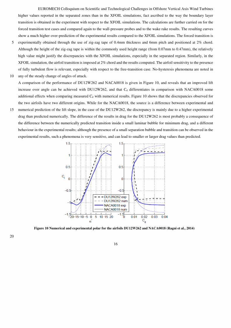
A comparison of the performance of DU12W262 and NACA0018 is given in Figure 10, and reveals that an improved lift
increase over angle can be achieved with DU12W262, and that Cd differentiates in comparison with NACA0018 some
additional effects when comparing measured Cd with numerical results. Figure 10 shows that the discrepancies observed for
the two airfoils have two different origins. While for the NACA0018, the source is a difference between experimental and
numerical prediction of the lift slope, in the case of the DU12W262, the discrepancy is mainly due to a higher experimental 15
drag than predicted numerically. The difference of the results in drag for the DU12W262 is most probably a consequence of
the difference between the numerically predicted transition inside a small laminar bubble for minimum drag, and a different
behaviour in the experimental results; although the presence of a small separation bubble and transition can be observed in the
experimental results, such a phenomena is very sensitive, and can lead to smaller or larger drag values than predicted.
Figure 10 Numerical and experimental polar for the airfoils DU12W262 and NACA0018 (Ragni et al., 2014)
20

EUROMECH Colloquium on Scientific and Technological Challenges in Offshore Vertical Axis Wind Turbines
17
5
Figure 11 Simulated and measured power coefficient (CP) of a three bladed VAWT as a function of tip speed ratio (λ). Left above: for the DU12W262 and NACA0018. Right above: using 2D experimental data for the DU12W262, NACA0015, NACA0018, 10 NACA0025 and NACA0030 using 2D numerical data (Ragni et al., 2014). Below: on the Ø2m DeepWind demonstrator rotor tested in wind tunnel experiment (Batisti et al., 2016) and (Bedon et al., 2016).
The simulations using the experimental and numerical airfoil polar results in Figure 10 and Figure 11 show that the new
DU12W262 airfoil out-performsthe NACA00xx series airfoils that were used in the initial population of the genetic
optimisation method from which the DU12W262 originated. However it is also realised, that the flow curvature effect 15
experienced by a blade section of a VAWT primarily can coped with operating rotors in a flow. Future experiments of a VAWT
blade section in rotation could provide an answer on the flow curvature effects, in particular on how it would supress or support
aerodynamic damping.
From Figure 11 (Below) a comparison of CP between the Ø2m Sandia- and the DeepWind demonstrator (DWD) rotor is made,
showing free field and wind tunnel measurements for specific conditions, and compared with computations conducted with 20
different airfoil databases on the Sandia rotor (Bedon et al, 2014). The difference in rotor efficiency for a simulated MW
turbine (Figure 11, Above) with measurements indicate Reynolds number influences of the scale compared to the full- scale.
The difference in CP (Figure 11, Below) seems to originate from differences between NACA0012 and DU26W12 airfoils
efficiency, rather than rpm differences. Also a note on the efficiency decrease of the DWD from tilted turbine operation.

EUROMECH Colloquium on Scientific and Technological Challenges in Offshore Vertical Axis Wind Turbines
18
3.2 Dynamic stall
Self-induced vibrations shown in (Skrzypiński et al., 2013) on a DU96-W180 airfoil at 90deg angle of attack revealed
instability effects, and compared with the lift coefficient performed by DUW262, in particular in deep stall, the airfoil should
be checked on potential occurrence of self-induced vibrations.
Figure 12 Static lift coefficients for different airfoils, obtained in LTT wind tunnel of TUDelft (Timmer and van Rooij, 2003) 5
3.3 Pitching of blades
(Pawsey, 2003) developed a concept with flexible elastomeric components, but concluded that a combination of lower torsional
stiffness while providing enough tensile stiffness, appears to be difficult. Another challenge is that the material properties
could change with time, thus affecting the sensitive response of the blades. The other concept tested by (Pawsey , 2003)
produces the restoring moment from inertial loads in rolling contact with the rotor. The results were promising, but are stated 10
to need more refinement to reduce effects of friction and parasitic drag. A comparison with the simple pendulum design of
(Sicard, 1977) and (Kentfield, 1978) predicts performance in the same range as the rolling concept, and further study is required
to see if the added control over the restoring moment is proving beneficial, or if it makes the turbine less reliable or more
expensive.
3.4 Curved blades 15
In a large scale phi-rotor, gravity-induced bending stress becomes significant, since the length of a typical phi-rotor blade is
almost three times (Deepwind~2.7, see (Paulsen et al. 2014)) a HAWT blade for a turbine with the same swept area and
solidity. (Paraschivou, 2002) and (Sutherland et al., 2012) mention that gravity-induced stress is related to rotor height-to-
diameter (H/D) ratio. Lower H/D ratio leads to greater gravitational stresses, but the type of airfoil can be tuned to minimize

EUROMECH Colloquium on Scientific and Technological Challenges in Offshore Vertical Axis Wind Turbines
19
gravity and radial aerodynamic influences. On the optimization for limit stresses occurring in the blades, a detailed analysis
of the Troposkien shape resulted in a modified Troposkien shape with max 5000×10-6 m/m in the blades (Paulsen et al.,2014)
and with industrialized blade section junctions (Paulsen et al.,2015).
On the influence of struts and parasitic drag, (Aagaard Madsen et al, 2014) estimations of this made the relative importance of
keeping parasitic drag low. 5
Sandia also made the conclusions that for phi-rotors 1) Two-blade design is more cost-effective than three blades, 2) Struts
should be kept short or possible eliminated since they add parasitic drag and cost, and 3) the blade airfoil shape should be
tailored (Sutherland et al., 2012).
3.5 Straight-bladed H-rotors
Sandia reported in 2012 that the H-rotor has a high potential for cost-effective offshore wind power generation (Sutherland et 10
al., 2012). They mention that the support bar for an H-rotor can be used as an aerodynamic braking system in strong winds.
The airbrake system is a standard aerodynamic brake for commercial airplanes, which deploys extended flaps during landing.
For straight-bladed small VAWTs, the gravity-induced bending stresses are of of less importance, as the blades are shorter and
have lower bending moment. The blades are more rigid at the same chord-length and thickness than a phi-rotor blade. They
are also positioned vertically, and supported by arms. The support arms present the component to endure gravity-induced 15
bending stresses, and it can be made tapered from the shaft to the blade. Drag-effects and damping occurs with potential
considerable amount.
The recent straight-bladed H-rotors are made of glass-fibre reinforced plastics (GFRP) and carbon fibre reinforced-composites
(CFRP), which can sustain continuous cycles of edgewise and flapwise bending stress during the blades service life. The
previously mentioned aerodynamic effects from parasitic drag and from struts (see Aagaard Madsen et al 2014) is compensated 20
by the increased performance of the H-rotor, as its blade equatorial portion to rotor height ratio becomes unity.
A multi-megawatt H-rotor requires investigations into strong and light-weight rotor-shafts, as an extended rotor shaft is prone
to vibration and fatigue, primarily due to torsional stress on the shaft.
Classical flutter might be a concern for straight-bladed (pitch-regulated) turbines, while dynamic stall-induced vibrations tend
to be a concern for stall-regulated turbines, (Hansen, 2007a) and (Hansen, 2007b). 25
The INFLOW project (Inflow, 2016) utilizes a rotor shape with straight blades utilizing power increase caused by operating
in a tilted offshore environment. Pitching and counter-rotation rotors are in this case obviously dependent on wind direction
influences. As mentioned, a trade-off between aerodynamic effects gained by an optimized H-rotor (such as INFLOW concept)
against structural effects and wind direction sensitivity experienced by a platform has to be investigated experimentally. 30

EUROMECH Colloquium on Scientific and Technological Challenges in Offshore Vertical Axis Wind Turbines
20
3.6 Loading
As mentioned, the DeepWind concept has a modified rotor blade shape, with a constraint defined as a limit blade strain,
allowing to park and to operate safely. Analyses of the floating system with respect to vibrations were carried out using
conventional NACA airfoils. A re-analysis has to be made with tailored DUWind airfoils, investigating on the risk of potential
rotor blade instabilities. 5
For the INFLOW concept, the load and power sensibility with direction changes of wind -, wave-and ocean current has to be
investigated and measured. This would also apply for wind shear and wind veer.
4 Conclusion / Discussion
Important fundamental criteria for a well operating straight- or curved-bladed VAWT should be attained from lessons learned
of addressing risk factors6 in DeepWind: 10
1. Structural Resonance of the elastic modes of the rotor can cause destructive vibrations if they are coincident with the
per rev excitations of the aerodynamic loads. All these resonances must be avoided. The best (but perhaps too
expensive) solution is to put all the elastic modes above the first three harmonics of the loading in the operating range
2. Instability: Flutter (aeroelastic instability) and whirl (divergence instability) must be predicted and avoided. These
are instabilities that are independent of wind excitation, they are self-excited, and will depend only on operating 15
speed.
3. Turbine performance depends on the stall regulation of power. Dynamic stall always affects VAWTs, and is
influenced by whether the airfoil is clean or soiled. The nature of the dynamic stall highly affects loads.
FVAWTs have to encounter excitation from the sea, and the impacts of the floating support structure on modes of vibration
have to be investigated. A careful analysis of the trade-off between efficiency and loads for CoE has to be made on both the 20
H-type and the curved bladed VAWT. Much in the same way as DeepWind, INFLOW is a demonstration of technologies,
trying to learn from the ongoing project. A number of important design changes of the initial H-design have been undertaken
in the project:
• The rotor blades intended to be used in the INFLOW prototype project VertiWind, blades with straight sections and twisted
helically around the central axis, was exchanged for a 3-bladed rotor design with straight blades. 25
• Classical flutter might be a concern for straight-bladed (pitch-regulated) turbines, while dynamic stall-induced vibrations
tend to be a concern for stall-regulated turbines.
• The initial design of a semi-submerged tri-floater with one turbine per substructure changed into two counter-rotating
turbines per floater, doubling the electrical output, and at the same time allowing large tilt excursions during operation.
6 Selecteted DeepWind consortium meeting communiqué 2011
EUROMECH Colloquium on Scientific and Technological Challenges in Offshore Vertical Axis Wind Turbines
21
However, work has to be done on the CoE added value from aerodynamics, loadings and particular design, and this has
to be verified experimentally in a planned test program in the next year.
The projects mentioned show that the VAWT technology is in a technological position to analyse and realize findings and
R&D solutions known from existing wind turbine industry and from the aircraft industry, striving for more efficient and less
costly machines. 5
Acknowledgements
This work is a part of the result of Work Package 5 of the INFLOW project, which was supported by the European Union’s
Seventh Programme for research, technological development and demonstration under grant agreement No 296043 and the
DeepWind project for funding under grant agreement No. 256769. Sandia National Laboratories gratefully acknowledges 10
support from the US Department of Energy (DOE) Wind and Water Power Program.
References
Aagaard Madsen, H. (ED.): Forskning i aeroelasticitet - EFP-98. (Denmark. Forskningscenter Risoe, Risoe-R; Nr. 1129(DA)),
1999.
Aagaard Madsen, H., Schmidt Paulsen U, Vitae, L Analysis of VAWT aerodynamics and design using the Actuator Cylinder 15
flow model Journal of Physics: Conference Series 555 (2014) 012065 doi:10.1088/1742-6596/555/1/012065
Apelfröjd, S., Eriksson, S., and Bernhoff, H.: A Review of Research on Large Scale Modern Vertical AxisWind Turbines at
Uppsala University, Energies, 9, 570, 2016; doi:10.3390/en9070570.
Ashwill, T. D., and Leonard, T. M.: Developments in blade shape design for a Darrieus vertical axis wind turbine SAND86-
1085, Sandia National Laboratories, Albuquerque, USA, 1986. 20
Bak, C.: (ED): Forskning i Aeroelasticitet, EFP-2002, risø-r-1434 (in Danish), 2002.
Bak, C., Aagaard Madsen, H., Fuglsang, P., and Rasmussen, F.: Observations and Hypothesis of Double Stall, Wind Energy,
2, 195-210, 1999.
Bak C, Gaunaa M and Antoniou I , Performance of the Risø-B1 Airfoil Family for Wind Turbines, Wind energy. Proceedings
of the Euromech colloquium. ed. / J. Peinke; P. Schaumann; S. Barth. Berlin : Springer, 2006. p. 231-234. 25
Bak C, Andersen P B, Madsen H A, Gaunaa M, Fuglsang P, Bove S, Design and Verification of Airfoils Resistant to Surface
Contamination and Turbulence Intensity, AIAA 2008-7050, 26th AIAA Applied Aerodynamics Conference, 18 - 21 August
2008, Honolulu, Hawaii
Bak P., Fuglsang P., Gaunaa, M., Antoniou, I.: Design and Verification of the Risø-P Airfoil Family for Wind Turbines,
Special topic conference: The science of making torque from wind - Delft (NL), ISBN 90-76468-10-9, 2004 30
EUROMECH Colloquium on Scientific and Technological Challenges in Offshore Vertical Axis Wind Turbines
22
Batisti, L., Benini, E., Brighenti, A., Racitti Castelli, M., DellAnna, S., Dossena, V., Persico, G., Schmidt Paulsen, U. and Friis
Pedersen, T.: Wind tunnel testing of the DeepWind demonstrator in design and tilted operating conditions, Energy, 111, 484-
497, 2016.
Bayly, D., and Kentfield, J., A vertical axis cyclogiro type wind-turbine with freely-hinged blades, Proceedings of the
Intersociety Energy Conversion Conference, 2, 2053, 1981 5
Beri, H., and Yao, Y.: Effect of Camber Airfoil on Self Starting of Vertical Axis Wind Turbine, Environ Sci Technol, 4 (3),
302-312, 2011a.
Beri, H., and Yao, Y.: Numerical simulation of Unsteady Flow to Show Self-starting of Vertical Axis Wind Turbine using
Fluent, Applied Sciences, 11 (6), 962-970, 2011b.
Borg, M., and Collu, M.: A Comparison on the Dynamics of a Floating Vertical Axis Wind Turbine on Three Different Floating 10
Support Structures, Energy Procedia, 53, 268–279, 2014, http://dx.doi.org/10.1016/j.egypro.2014.07.236.
Borg, M., Shires, A., and Collu, M.: Offshore Floating Vertical Axis Wind Turbines, Dynamics Modelling State of the Art.
Part I: Aerodynamics, Renew Sust Energ Rev, 39, 1214–1225, 2014, http://dx.doi.org/10.1016/j.rser.2014.07.096.
Cahay, M., Luquiau, E., Smadja, C., and Silvert, F.: Use of a Vertical Wind Turbine in an Offshore Floating Wind Farm,
Offshore Technol Conf, Houston, TX, USA, OTC-21705-MS, 2011, http://dx.doi.org/10.4043/21705-MS. 15
Castelein, D., Ragni, D., Tescione, G., Simão Ferreira, C. J., and Gaunaa, M.: Creating a benchmark of Vertical Axis Wind
Turbines in Dynamic Stall for validating numerical models, Master of Science Thesis, TUDelft, AIAA 2015-0723, 2015.
Cheng, Z.: Dynamic Modelling and Analysis of Three Floating Wind Turbine Concepts with Vertical Axis Rotor. In
Proceedings of the Twenty-fifth (2015) International Ocean and Polar Engineering Conference, 2015. ISBN 978-1-880653-
89-0; ISSN 1098-6189 20
The DeepWind Project, [Accessed 25.02.2016] Available from http://www.deepwind.eu
Ertem, S., and Simão Ferreira, C., Gaunaa, M., and Madsen, H. Aa.: Aerodynamic Optimization of Vertical Axis Wind Turbine
with Trailing Edge Flaps. Proceedings of the 34th Wind Energy Symposium, AIAA SciTech, (AIAA 2016-1735).
Simão Ferreira, C., and Geurts, B.: Aerofoil optimization for vertical axis wind turbines, Wind Energy, 18, 1371–1385, 2015
Fowler, M., Bull, D., and Goupee, A.: A Comparison of Platform Options for Deep-water Floating Offshore Vertical Axis 25
Wind Turbines: An Initial Study, Sandia National Laboratories Technical Report, SAND2014-16800, August 2014.
Grylls, W., Dale, B., and Sarr, P.: A Theoretical and experimental investigation into the variable pitch vertical axis wind
turbine, 2nd International Symposium on Wind Energy Systems, 2, E–9, 1978
Fuglsang P, Bak C, Development of the Risø Wind Turbine Airfoils, Wind Energ. 2004; 7:145–162 (DOI: 10.1002/we.117)
Hansen, M. H.: Stall induced virbrations of a blade section in deep-stall, Research in Aeroelasticity EFP-2007-II, Risø-R-30
1698(EN), 2007.

EUROMECH Colloquium on Scientific and Technological Challenges in Offshore Vertical Axis Wind Turbines
23
Griffith, D. T., Paquette, J., Barone, M., Goupee, A., Fowler, M., Bull, D., and Owens, B.: A study of rotor and platform
design trade-offs for large-scale floating vertical axis wind turbines, Science of making torque from wind conference, Munich,
Germany, 2016.
Hansen, M. H.: Aeroelastic Instability Problems for Wind Turbines, Wind Energy, 10, 551–577, 2007.
Heinz, J. C., Sørensen, N. N., Zahle, and F., Skrzypiński, W.: Vortex-induced vibrations on a modern wind turbine blade, 5
Wind Energy, 2016, doi: 10.1002/we.1967.
Henderson, A. R., and Witcher, D.: Floating Offshore Wind Energy - A Review of the Current Status and an Assessment of
the Prospects, Wind Engineering, 34 (1), 01–16, 2010.
Hoerner, S. F.: Fluid-Dynamic Drag. Hoerner Fluid Dynamics: Brick Town, 1975.
Hoerner, S. F., and Borst, H. V.: Fluid dynamic Lift: Hoerner fluid Dynamics: Brick Town, 1969. 10
Howell, R., Qin, N., Edwards, J., and Durrani, N.: Wind tunnel and numerical study of a small vertical axis wind turbine.
Renewable Energy, 35, 412–422, 2010.
INFLOW, European FP7 project for demonstration [Accessed 25-02-2016] Available from: http://www.inflow-fp7.eu
Kelly, J. A., and Hayter, N-L. F.: Lift and pitching moment at low speeds of the NACA 64A010 airfoil section equipped with
various combinations of a leading-edge slat, leading-edge flap, split flap, and double-slotted flap, NACA TN3007, National 15
Advisory Committee for Aeronautics, 1953.
Kentfield, J.: A Hybrid Cyclogiro-Darrieus Rotor Wind Turbine. Proceedings of 1st Brazilian Energy Congress, B, 4448-463,
1978.
Kirke, B., and Lazauskas, L.: Experimental verification of a mathematical model for predicting the performance of a self-
acting vertical axis wind turbine, Wind Engineering, 17 (2), 58–66, 1993. 20
Klimas, P.C. and Sladky, J. F.: Pumped Spoiling VAWT Control, 4th ASME Wind Energy Symposium, February, 1985a.
Klimas, P.C, and Sladky J. F.: Vertical axis wind turbine power regulation through centrifugally pumped lift spoiling,
INTERSOL 1985, 1985b.
Krüger, W.: Wind tunnel investigations on a changed Mustang profile with nose flap force and pressure -distribution
measurements, NACA technical memorandum No. 1177, 1947. 25
Kuma, H., Takao, M., Beppy, T., Maeda, T., Kamada, Y., and Kamemoto, K.: A straight-bladed vertical axis wind turbine
with a directed guide vane – mechanism of performance improvement, Proceedings of 27th International Conference on
Offshore Mechanics and Arctic Engineering, Portugal, Paper No. OMAE2008-57233, 2007.
Leishmann, J. G., and Beddoes, T. S.: A Semi-Empirical Model for Dynamic Stall, Journal of the American Helicopter Society,
34 (3), 3-17(15), 1989. 30
Li, Y., Tagawa, K., and Liu, W.: Performance effects of attachment on blade on a straight-bladed vertical axis wind turbine.
Curr Appl Phys, 10, S335–S338, 2010.
EUROMECH Colloquium on Scientific and Technological Challenges in Offshore Vertical Axis Wind Turbines
24
Merz, K O and Svendsen H G, A control algorithm for the deepwind floating vertical-axis wind turbine. Journal of Renewable
and Sustainable Energy 5, 063136 (2013); doi: 10.1063/1.4854675
Meyer, R. E.: Stability Analysis of Multi-Megawatt Darrieus- Type Floating Vertical Axis Wind Turbines . Thesis DTU Wind
Energy-M-0099, 2016
Nobile, R., Vahdati, M., Barlow, J., and Mewburn-Crook, A.: Dynamic stall for a Vertical Axis Wind Turbine in a two-5
dimensional study, World Renewable Energy Congress, Sweden, 2011.
Oler, J. W., Strickland, J. H., Im, B. J., and Graham, G. H.: Dynamic stall regulation of the Darrieus turbine, SAND83-7029,
Sandia National Laboratories, Albuquerque, 1983.
Owens, B. C., and Griffith, D. T.: Aeroelastic stability investigations for large-scale vertical axis wind turbines, J. Phys. Conf.
Ser., 524 (1), 12092, 2014. 10
Owens, B. C., Griffith, D. T., and Hurtado, J. E.: Modal Dynamics and Stability of Large Multi-megawatt Deepwater Offshore
Vertical-axis Wind Turbines: Initial Support Structure and Rotor Design Impact Studies, 32nd ASME Wind Energy
Symposium, National Harbor, MD, USA, January 2014.
Paraschivoiu, I.: Wind turbine design with emphasis on Darrieus concept, (Quebec: Presses Internationales Polytechnique),
2002. 15
Pawsey, N. C. K.: Development and evaluation of passive variable-pitch vertical axis wind turbines, PhD Thesis, The
University of New South Wales, 2003.
Paulsen, Uwe S. and Madsen, Helge A. and Kragh, Knud A. and Nielsen, Per H. and Baran, Ismet and Hattel, Jesper and
Ritchie, Ewen and Leban, Krisztina and Svendsen, Harald and Berthelsen, Petter A. (2014) DeepWind-from Idea to 5 MW
Concept. Energy Procedia, 53 . pp. 23-33. ISSN 1876-6102 20
Paulsen, U. S., Borg, M., Madsen, H. Aa., Pedersen, T. F., Hattel, J., Ritchie, E., Ferreira, C. S., Svendsen, H., Berthelsen, P.
A., and Smadja, C.: Outcomes of the Deepwind conceptual design, Energy Procedia, 80, 329-341, 2015,
http://dx.doi.org/10.1016/j.egypro.2015.11.437.
Pirrung et al., 2016. Dynstall report. To be published
Ragni, D., Simão Ferreira, C. and Correale, C.: Experimental investigation of an optimized airfoil for vertical-axis wind 25
turbines, Wind Energ, 18, 1629-1643, 2014. DOI: 10.1002/we.1780 2014
Riegels FW 1961. Aerofoil sections. Butterworth
Ritchie, E., Leban, K., and Paulsen, U. S.: Electrical aspects of the DeepWind 5 MW floating Vertical Axis Wind Turbine, to
be submitted in Journal of Energy Challenges and Mechanics, 2016a.
Ritchie, E., Leban, K., Trintis, I., Nica, F. V. T., Boian, D., Biris, C., Burlacu, P. D., Shivachev, S., and Paulsen, U. S.: On the 30
Design and Performance of a Power Electronics Converter for the DeepWind project, EUROMECH Colloquium on Scientific
and Technological Challenges in Offshore Vertical Axis Wind Turbines Delft, 2016b.
EUROMECH Colloquium on Scientific and Technological Challenges in Offshore Vertical Axis Wind Turbines
25
Sandia VAWT project: Innovative offshore vertical-axis wind turbine rotors [Accessed 3.03.2016] Available from:
http://energy.sandia.gov/energy/renewable-energy/wind-power/offshore-wind/innovative-offshore-vertical-axis-wind-
turbine-rotors/
Scheurich, F., and Brown, R.: Vertical-axis wind turbines in oblique flow: sensitivity to rotor geometry. EWEA Annual event
(formerly known as EWEC) (2011). 5
Sicard, C.: Fluid current turbine. United States Patent 4.048.947, 1977.
Skrzypiński, W., and Gaunaa, M.: Wind turbine blade vibration at standstill conditions — the effect of imposing lag on the
aerodynamic response of an elastically mounted airfoil, Wind Energy, 2014, doi: 10.1002/we.1712.
Skrzypiński, W., Gaunaa, M., Sørensen, N., Zahle, F., and Heinz, J.: Vortex-induced vibrations of a DU96-W-180 airfoil at
90° angle of attack, Wind Energ, 2013. DOI: 10.1002/we.1647 10
Sutherland, H. J., Berg, D. E., and Ashwill, T. D.: A retrospective of VAWT technology, SAND2012-0304, Sandia National
Laboratories, Albuquerque, USA, 2012.
Takao, M., Maeda, T., Kamada, Y., Oki, M., and Kuma, H.: A straight-bladed vertical axisi wind turbine with a directed guide
vane row, Proceedings of the 5th Joint ASME/JSME Fluids Engineering Conference, San Diego, USA, Paper No.
FEDSM2007-37422, 2007. 15
Takao, M., Takita, H., and Saito, Y.: Experimental study of a straight-bladed vertical axis wind turbine with a directed vane
row, Proceedings of the 28th International Conference on Ocean, Offshore and Arctic Engineering, Honolulu, 2009.
Templin R. J., and South, P.: Canadian wind energy program, Proceedings of the vertical-axis wind turbine technology
workshop Albuquerque, New Mexico, May 18-20, report SAND 76-5586, 1976.
Theodorsen, T.: General theory of aerodynamic instability and the mechanism of flutter, NACA report 496, 1935. 20
Thirstrup Petersen, J., Thomsen, K., and Aagaard Madsen, H.: Stall strips can control edgewise vibrations, AED-RB-6(EN),
1998.
Timmer, W. A., and van Rooij, R. P. J. O. M.: Summary of the Delft University Wind Turbine Dedicated Airfoils, Journal of
Solar Energy Engineering, 125(4), 2003.
Tjiu,W., Marnoto, T., Mat, S., Ruslan, M. H., and Sopian, K.: Darrieus vertical axis wind turbine for power generation I: 25
Assessment of Darrieus VAWT configurations, Renew. Energ, 75, 50–67, 2015
Verelst, D. R. S., Aagaard Madsen H., Kragh, K. A. and Belloni, F.: Detailed Load Analysis of the baseline 5MW DeepWind
Concept, DTU Wind Energy, E-0057, 2014.
Walters, R. E., Fanucci, J. B., Hill, P. W., and Migliore P. G.: Vertical axis wind turbine development, SAND 5665084, 1979.
Wang K, Moan T and Hansen MOL A method for modeling of floating vertical axis wind turbine. In Proceedings of the 30
ASME 2013 32nd International Conference on Ocean, Offshore and Arctic Engineering, OMAE2013-10289.
Yusuf Billah, K., and Scanlan, R. H.: Resonance, Tacoma Narrow bridge failure, and undergraduate physics textbooks. Am.
J. Phys., 59, 2, 1991.