Embed Size (px)
Citation preview
This is an electronic reprint of the original article.This reprint may differ from the original in pagination and typographic detail.
Powered by TCPDF (www.tcpdf.org)
This material is protected by copyright and other intellectual property rights, and duplication or sale of all or part of any of the repository collections is not permitted, except that material may be duplicated by you for your research use or educational purposes in electronic or print form. You must obtain permission for any other use. Electronic or print copies may not be offered, whether for sale or otherwise to anyone who is not an authorised user.
Heidari, Hamidreza; Rassõlkin, Anton; Kallaste, Ants; Vaimann, Toomas; Andriushchenko,Ekaterina; Belahcen, Anouar; Lukichev, Dmitry V.A review of synchronous reluctance motor-drive advancements
Published in:Sustainability (Switzerland)
DOI:10.3390/su13020729
Published: 02/01/2021
Document VersionPublisher's PDF, also known as Version of record
Published under the following license:CC BY
Please cite the original version:Heidari, H., Rassõlkin, A., Kallaste, A., Vaimann, T., Andriushchenko, E., Belahcen, A., & Lukichev, D. V. (2021).A review of synchronous reluctance motor-drive advancements. Sustainability (Switzerland), 13(2), 1-37. [729].https://doi.org/10.3390/su13020729
sustainability
Review
A Review of Synchronous Reluctance Motor-DriveAdvancements
Hamidreza Heidari 1,* , Anton Rassõlkin 1,2 , Ants Kallaste 1 , Toomas Vaimann 1,2 ,Ekaterina Andriushchenko 1, Anouar Belahcen 1,3 and Dmitry V. Lukichev 2
�����������������
Citation: Heidari, H.; Rassõlkin, A.;
Kallaste, A.; Vaimann, T.;
Andriushchenko, E.; Belahcen, A.;
Lukichev, D.V. A Review of
Synchronous Reluctance Motor-Drive
Advancements. Sustainability 2021, 13,
729. https://doi.org/10.3390/
su13020729
Received: 11 December 2020
Accepted: 8 January 2021
Published: 13 January 2021
Publisher’s Note: MDPI stays neu-
tral with regard to jurisdictional clai-
ms in published maps and institutio-
nal affiliations.
Copyright: © 2021 by the authors. Li-
censee MDPI, Basel, Switzerland.
This article is an open access article
distributed under the terms and con-
ditions of the Creative Commons At-
tribution (CC BY) license (https://
creativecommons.org/licenses/by/
4.0/).
1 Department of Electrical Power Engineering and Mechatronics, Tallinn University of Technology,Ehitajate tee 5, 19086 Tallinn, Estonia; [email protected] (A.R.); [email protected] (A.K.);[email protected] (T.V.); [email protected] (E.A.); [email protected] (A.B.)
2 Faculty of Control Systems and Robotics, ITMO University, 197101 Saint Petersburg, Russia;[email protected]
3 Department of Electrical Engineering and Automation, Aalto University, P.O. Box 15500 Aalto, Finland* Correspondence: [email protected]; Tel.: +372-56139797
Abstract: Recent studies show that synchronous reluctance motors (SynRMs) present promisingtechnologies. As a result, research on trending SynRMs drive systems has expanded. This workdisseminates the recent developments of design, modeling, and more specifically, control of thesemotors. Firstly, a brief study of the dominant motor technologies compared to SynRMs is carried out.Secondly, the most prominent motor control methods are studied and classified, which can comein handy for researchers and industries to opt for a proper control method for motor drive systems.Finally, the control strategies for different speed regions of SynRM are studied and the transitionsbetween trajectories are analyzed.
Keywords: synchronous reluctance motor; efficiency map analysis; efficient motor technology;efficient control strategy; direct torque control; field-oriented control; predictive torque control;sensorless control; maximum torque per ampere; field-weakening
1. Introduction
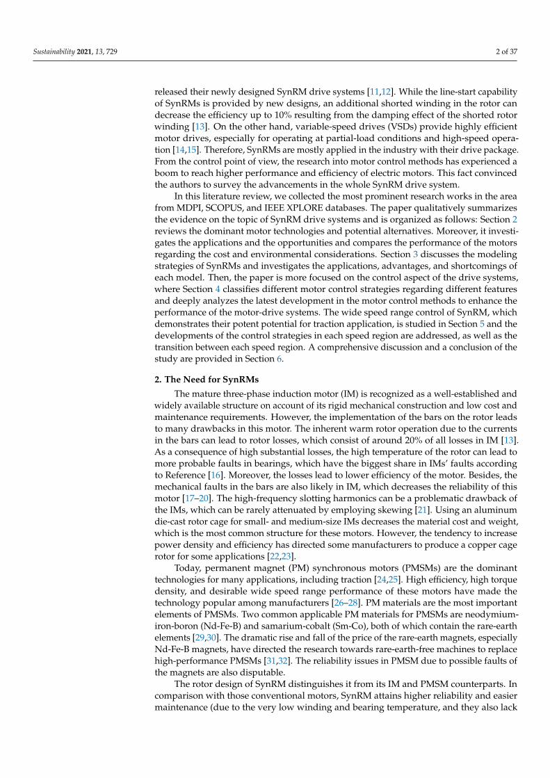
Industrial development has a significant impact on global warming and climatechange. Considering the human impact on the environment from the aspect of resources,there are high demands for effective systems. This fact leads to the investigation ofalternative developments in the field of electrical machines, as well. Energy efficiencyrequirements have led to the research and development of alternative technologies toproduce electrical motors. The recent advances in the motor design area have providedmanufacturers with some opportunities to save energy, use less rare-earth materials, anddecrease the cost in terms of material and manufacturing processes. A life cycle analysisof electrical motor-drive systems by Rassõlkin et al. provides a comprehensive study onsynchronous reluctance motors (SynRM) [1]. This study shows that starting from theacquisition of the materials, through manufacturing, transporting, and marketing, SynRMsare competitive at the usage stage, and efficient at the recycling phase. Lack of rare-earthmaterials, low cost, comparable constant-power speed range, maximum torque per ampere,and efficiency of SynRMs, in particular, permanent magnet (PM)-assisted ones (PMSynRM),have made these motors an interesting choice in traction [2,3] and more-electrical aircraftapplications [4–6]. Besides, the need for highly efficient motors in centrifugal machines,conveyor systems, fans and pumps, cranes, compressors, elevators, crushers, and generalmachine building (winders, extruders, and servo pumps) can be met by SynRM [7–10].
Although almost a century has passed since the first invention of SynRMs, they haverecently gained a lot of attention resulted from the emergence of the power-electronicdevice. In the last decade, the leading manufacturers such as SIEMENS and ABB have
Sustainability 2021, 13, 729. https://doi.org/10.3390/su13020729 https://www.mdpi.com/journal/sustainability
Sustainability 2021, 13, 729 2 of 37
released their newly designed SynRM drive systems [11,12]. While the line-start capabilityof SynRMs is provided by new designs, an additional shorted winding in the rotor candecrease the efficiency up to 10% resulting from the damping effect of the shorted rotorwinding [13]. On the other hand, variable-speed drives (VSDs) provide highly efficientmotor drives, especially for operating at partial-load conditions and high-speed opera-tion [14,15]. Therefore, SynRMs are mostly applied in the industry with their drive package.From the control point of view, the research into motor control methods has experienced aboom to reach higher performance and efficiency of electric motors. This fact convincedthe authors to survey the advancements in the whole SynRM drive system.
In this literature review, we collected the most prominent research works in the areafrom MDPI, SCOPUS, and IEEE XPLORE databases. The paper qualitatively summarizesthe evidence on the topic of SynRM drive systems and is organized as follows: Section 2reviews the dominant motor technologies and potential alternatives. Moreover, it investi-gates the applications and the opportunities and compares the performance of the motorsregarding the cost and environmental considerations. Section 3 discusses the modelingstrategies of SynRMs and investigates the applications, advantages, and shortcomings ofeach model. Then, the paper is more focused on the control aspect of the drive systems,where Section 4 classifies different motor control strategies regarding different featuresand deeply analyzes the latest development in the motor control methods to enhance theperformance of the motor-drive systems. The wide speed range control of SynRM, whichdemonstrates their potent potential for traction application, is studied in Section 5 and thedevelopments of the control strategies in each speed region are addressed, as well as thetransition between each speed region. A comprehensive discussion and a conclusion of thestudy are provided in Section 6.
2. The Need for SynRMs
The mature three-phase induction motor (IM) is recognized as a well-established andwidely available structure on account of its rigid mechanical construction and low cost andmaintenance requirements. However, the implementation of the bars on the rotor leadsto many drawbacks in this motor. The inherent warm rotor operation due to the currentsin the bars can lead to rotor losses, which consist of around 20% of all losses in IM [13].As a consequence of high substantial losses, the high temperature of the rotor can lead tomore probable faults in bearings, which have the biggest share in IMs’ faults accordingto Reference [16]. Moreover, the losses lead to lower efficiency of the motor. Besides, themechanical faults in the bars are also likely in IM, which decreases the reliability of thismotor [17–20]. The high-frequency slotting harmonics can be a problematic drawback ofthe IMs, which can be rarely attenuated by employing skewing [21]. Using an aluminumdie-cast rotor cage for small- and medium-size IMs decreases the material cost and weight,which is the most common structure for these motors. However, the tendency to increasepower density and efficiency has directed some manufacturers to produce a copper cagerotor for some applications [22,23].
Today, permanent magnet (PM) synchronous motors (PMSMs) are the dominanttechnologies for many applications, including traction [24,25]. High efficiency, high torquedensity, and desirable wide speed range performance of these motors have made thetechnology popular among manufacturers [26–28]. PM materials are the most importantelements of PMSMs. Two common applicable PM materials for PMSMs are neodymium-iron-boron (Nd-Fe-B) and samarium-cobalt (Sm-Co), both of which contain the rare-earthelements [29,30]. The dramatic rise and fall of the price of the rare-earth magnets, especiallyNd-Fe-B magnets, have directed the research towards rare-earth-free machines to replacehigh-performance PMSMs [31,32]. The reliability issues in PMSM due to possible faults ofthe magnets are also disputable.
The rotor design of SynRM distinguishes it from its IM and PMSM counterparts. Incomparison with those conventional motors, SynRM attains higher reliability and easiermaintenance (due to the very low winding and bearing temperature, and they also lack
Sustainability 2021, 13, 729 3 of 37
cage or PMs in rotor structure) [33,34], lower cost (due to the lack of PMs in comparisonwith PMSM), faster dynamic response (due to smaller size in the same power range andlower moment of inertia), higher speed range (due to the wide constant-power operationin comparison with IM) [35] and higher efficiency in the same power range with the sameframe size (due to the cold rotor operation in comparison with IM) [13,36], and higherpower density and higher torque per ampere (in comparison with IM) [4,37]. In this sense,SynRM offers the high performance of PMSM, while it can be as cheap, simple, and service-friendly as IM. Therefore, the attention paid for these motors in high-speed applications hasexperienced continuous growth in the literature, which has convinced the electric vehicles(EVs) and hybrid electric vehicles (HEVs) manufacturers to apply SynRMs as an alternativefor PMSM [38–40]. Having said this, the possibility of the drive with the same VSDs for IMand PMSM in various recently designed VSDs has provided a viable development base forSynRM [41]. All in all, the high efficiency of SynRMs against IM has attracted attentionfor applications such as pumps and fans. Also, the high performance and especially widespeed operation capability with the consideration of lack of rare-earth PMs compared tothe PMSM has attracted the researchers to study these motors for traction application.
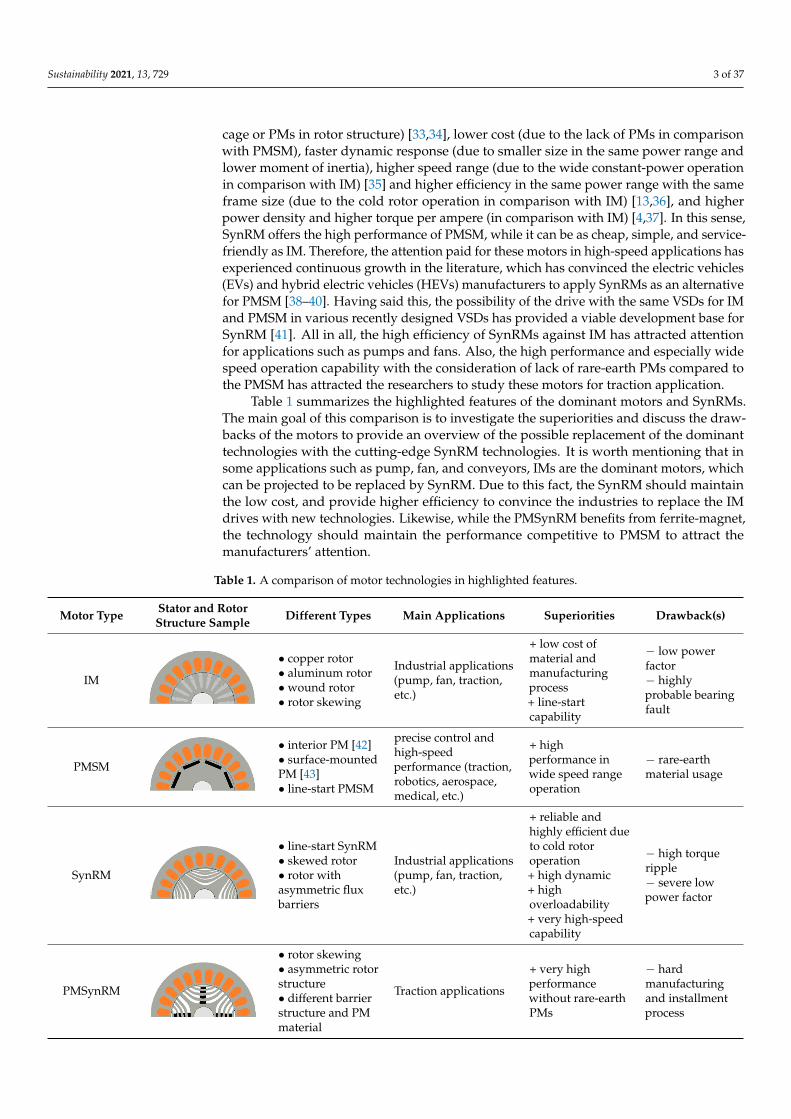
Table 1 summarizes the highlighted features of the dominant motors and SynRMs.The main goal of this comparison is to investigate the superiorities and discuss the draw-backs of the motors to provide an overview of the possible replacement of the dominanttechnologies with the cutting-edge SynRM technologies. It is worth mentioning that insome applications such as pump, fan, and conveyors, IMs are the dominant motors, whichcan be projected to be replaced by SynRM. Due to this fact, the SynRM should maintainthe low cost, and provide higher efficiency to convince the industries to replace the IMdrives with new technologies. Likewise, while the PMSynRM benefits from ferrite-magnet,the technology should maintain the performance competitive to PMSM to attract themanufacturers’ attention.
Table 1. A comparison of motor technologies in highlighted features.
Motor Type Stator and RotorStructure Sample Different Types Main Applications Superiorities Drawback(s)
IM
Sustainability 2021, 13, x FOR PEER REVIEW 3 of 38
The rotor design of SynRM distinguishes it from its IM and PMSM counterparts. In comparison with those conventional motors, SynRM attains higher reliability and easier maintenance (due to the very low winding and bearing temperature, and they also lack cage or PMs in rotor structure) [33,34], lower cost (due to the lack of PMs in comparison with PMSM), faster dynamic response (due to smaller size in the same power range and lower moment of inertia), higher speed range (due to the wide constant-power operation in comparison with IM) [35] and higher efficiency in the same power range with the same frame size (due to the cold rotor operation in comparison with IM) [13,36], and higher power density and higher torque per ampere (in comparison with IM) [4,37]. In this sense, SynRM offers the high performance of PMSM, while it can be as cheap, simple, and ser-vice-friendly as IM. Therefore, the attention paid for these motors in high-speed applica-tions has experienced continuous growth in the literature, which has convinced the elec-tric vehicles (EVs) and hybrid electric vehicles (HEVs) manufacturers to apply SynRMs as an alternative for PMSM [38–40]. Having said this, the possibility of the drive with the same VSDs for IM and PMSM in various recently designed VSDs has provided a viable development base for SynRM [41]. All in all, the high efficiency of SynRMs against IM has attracted attention for applications such as pumps and fans. Also, the high performance and especially wide speed operation capability with the consideration of lack of rare-earth PMs compared to the PMSM has attracted the researchers to study these motors for trac-tion application.
Table 1 summarizes the highlighted features of the dominant motors and SynRMs. The main goal of this comparison is to investigate the superiorities and discuss the draw-backs of the motors to provide an overview of the possible replacement of the dominant technologies with the cutting-edge SynRM technologies. It is worth mentioning that in some applications such as pump, fan, and conveyors, IMs are the dominant motors, which can be projected to be replaced by SynRM. Due to this fact, the SynRM should maintain the low cost, and provide higher efficiency to convince the industries to replace the IM drives with new technologies. Likewise, while the PMSynRM benefits from ferrite-mag-net, the technology should maintain the performance competitive to PMSM to attract the manufacturers’ attention.
Table 1. A comparison of motor technologies in highlighted features.
Motor Type Stator and Rotor Structure Sample Different Types Main Applications Superiorities Drawback(s)
IM
• copper rotor • aluminum rotor • wound rotor • rotor skewing
Industrial applications (pump, fan, traction, etc.)
+ low cost of material and manufacturing process + line-start capability
− low power factor − highly probable bearing fault
PMSM
• interior PM [42] • surface-mounted PM [43] • line-start PMSM
precise control and high-speed performance (traction, robotics, aerospace, medical, etc.)
+ high performance in wide speed range operation
− rare-earth material usage
SynRM
• line-start SynRM • skewed rotor • rotor with asymmetric flux barriers
Industrial applications (pump, fan, traction, etc.)
+ reliable and highly efficient due to cold rotor operation + high dynamic + high overloadability + very high-speed capability
− high torque ripple − severe low power factor
• copper rotor• aluminum rotor• wound rotor• rotor skewing
Industrial applications(pump, fan, traction,etc.)
+ low cost ofmaterial andmanufacturingprocess+ line-startcapability
− low powerfactor− highlyprobable bearingfault
PMSM
Sustainability 2021, 13, x FOR PEER REVIEW 3 of 38
The rotor design of SynRM distinguishes it from its IM and PMSM counterparts. In comparison with those conventional motors, SynRM attains higher reliability and easier maintenance (due to the very low winding and bearing temperature, and they also lack cage or PMs in rotor structure) [33,34], lower cost (due to the lack of PMs in comparison with PMSM), faster dynamic response (due to smaller size in the same power range and lower moment of inertia), higher speed range (due to the wide constant-power operation in comparison with IM) [35] and higher efficiency in the same power range with the same frame size (due to the cold rotor operation in comparison with IM) [13,36], and higher power density and higher torque per ampere (in comparison with IM) [4,37]. In this sense, SynRM offers the high performance of PMSM, while it can be as cheap, simple, and ser-vice-friendly as IM. Therefore, the attention paid for these motors in high-speed applica-tions has experienced continuous growth in the literature, which has convinced the elec-tric vehicles (EVs) and hybrid electric vehicles (HEVs) manufacturers to apply SynRMs as an alternative for PMSM [38–40]. Having said this, the possibility of the drive with the same VSDs for IM and PMSM in various recently designed VSDs has provided a viable development base for SynRM [41]. All in all, the high efficiency of SynRMs against IM has attracted attention for applications such as pumps and fans. Also, the high performance and especially wide speed operation capability with the consideration of lack of rare-earth PMs compared to the PMSM has attracted the researchers to study these motors for trac-tion application.
Table 1 summarizes the highlighted features of the dominant motors and SynRMs. The main goal of this comparison is to investigate the superiorities and discuss the draw-backs of the motors to provide an overview of the possible replacement of the dominant technologies with the cutting-edge SynRM technologies. It is worth mentioning that in some applications such as pump, fan, and conveyors, IMs are the dominant motors, which can be projected to be replaced by SynRM. Due to this fact, the SynRM should maintain the low cost, and provide higher efficiency to convince the industries to replace the IM drives with new technologies. Likewise, while the PMSynRM benefits from ferrite-mag-net, the technology should maintain the performance competitive to PMSM to attract the manufacturers’ attention.
Table 1. A comparison of motor technologies in highlighted features.
Motor Type Stator and Rotor Structure Sample Different Types Main Applications Superiorities Drawback(s)
IM
• copper rotor • aluminum rotor • wound rotor • rotor skewing
Industrial applications (pump, fan, traction, etc.)
+ low cost of material and manufacturing process + line-start capability
− low power factor − highly probable bearing fault
PMSM
• interior PM [42] • surface-mounted PM [43] • line-start PMSM
precise control and high-speed performance (traction, robotics, aerospace, medical, etc.)
+ high performance in wide speed range operation
− rare-earth material usage
SynRM
• line-start SynRM • skewed rotor • rotor with asymmetric flux barriers
Industrial applications (pump, fan, traction, etc.)
+ reliable and highly efficient due to cold rotor operation + high dynamic + high overloadability + very high-speed capability
− high torque ripple − severe low power factor
• interior PM [42]• surface-mountedPM [43]• line-start PMSM
precise control andhigh-speedperformance (traction,robotics, aerospace,medical, etc.)
+ highperformance inwide speed rangeoperation
− rare-earthmaterial usage
SynRM
Sustainability 2021, 13, x FOR PEER REVIEW 3 of 38
The rotor design of SynRM distinguishes it from its IM and PMSM counterparts. In comparison with those conventional motors, SynRM attains higher reliability and easier maintenance (due to the very low winding and bearing temperature, and they also lack cage or PMs in rotor structure) [33,34], lower cost (due to the lack of PMs in comparison with PMSM), faster dynamic response (due to smaller size in the same power range and lower moment of inertia), higher speed range (due to the wide constant-power operation in comparison with IM) [35] and higher efficiency in the same power range with the same frame size (due to the cold rotor operation in comparison with IM) [13,36], and higher power density and higher torque per ampere (in comparison with IM) [4,37]. In this sense, SynRM offers the high performance of PMSM, while it can be as cheap, simple, and ser-vice-friendly as IM. Therefore, the attention paid for these motors in high-speed applica-tions has experienced continuous growth in the literature, which has convinced the elec-tric vehicles (EVs) and hybrid electric vehicles (HEVs) manufacturers to apply SynRMs as an alternative for PMSM [38–40]. Having said this, the possibility of the drive with the same VSDs for IM and PMSM in various recently designed VSDs has provided a viable development base for SynRM [41]. All in all, the high efficiency of SynRMs against IM has attracted attention for applications such as pumps and fans. Also, the high performance and especially wide speed operation capability with the consideration of lack of rare-earth PMs compared to the PMSM has attracted the researchers to study these motors for trac-tion application.
Table 1 summarizes the highlighted features of the dominant motors and SynRMs. The main goal of this comparison is to investigate the superiorities and discuss the draw-backs of the motors to provide an overview of the possible replacement of the dominant technologies with the cutting-edge SynRM technologies. It is worth mentioning that in some applications such as pump, fan, and conveyors, IMs are the dominant motors, which can be projected to be replaced by SynRM. Due to this fact, the SynRM should maintain the low cost, and provide higher efficiency to convince the industries to replace the IM drives with new technologies. Likewise, while the PMSynRM benefits from ferrite-mag-net, the technology should maintain the performance competitive to PMSM to attract the manufacturers’ attention.
Table 1. A comparison of motor technologies in highlighted features.
Motor Type Stator and Rotor Structure Sample Different Types Main Applications Superiorities Drawback(s)
IM
• copper rotor • aluminum rotor • wound rotor • rotor skewing
Industrial applications (pump, fan, traction, etc.)
+ low cost of material and manufacturing process + line-start capability
− low power factor − highly probable bearing fault
PMSM
• interior PM [42] • surface-mounted PM [43] • line-start PMSM
precise control and high-speed performance (traction, robotics, aerospace, medical, etc.)
+ high performance in wide speed range operation
− rare-earth material usage
SynRM
• line-start SynRM • skewed rotor • rotor with asymmetric flux barriers
Industrial applications (pump, fan, traction, etc.)
+ reliable and highly efficient due to cold rotor operation + high dynamic + high overloadability + very high-speed capability
− high torque ripple − severe low power factor
• line-start SynRM• skewed rotor• rotor withasymmetric fluxbarriers
Industrial applications(pump, fan, traction,etc.)
+ reliable andhighly efficient dueto cold rotoroperation+ high dynamic+ highoverloadability+ very high-speedcapability
− high torqueripple− severe lowpower factor
PMSynRM
Sustainability 2021, 13, x FOR PEER REVIEW 4 of 38
PMSynRM
• rotor skewing • asymmetric rotor structure • different barrier structure and PM material
Traction applications
+ very high performance without rare-earth PMs
− hard manufacturing and installment process
In the rest of this section, the advancement of SynRMs is investigated and the pro-spect of their development in the industry is projected in different applications.
2.1. SynRM As its name suggests, SynRM produces reluctance torque resulting from changing
the magnetic reluctance, which is also called magnetic resistance. The magnetic flux flows into the lowest magnetic resistance. Therefore, the produced flux by the stator flows into the lowest magnetic resistance in the rotor. Hence, if the rotor is not aligned with the flux, the reluctance torque will rotate the rotor in the direction with minimum magnetic re-sistance. In this sense, the saliency ratio causes magnetomotive force (MMF) and the re-luctance torque spins the rotor.
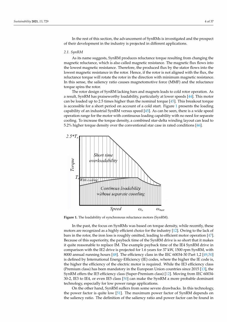
The rotor design of SynRM lacking bars and magnets leads to cold rotor operation. As a result, SynRM has praiseworthy loadability, particularly at lower speeds [44]. This motor can be loaded up to 2.5 times higher than the nominal torque [45]. This breakout torque is accessible for a short period on account of a cold start. Figure 1 presents the loading capability of an industrial SynRM versus speed [45]. As can be seen, there is a wide speed operation range for the motor with continuous loading capability with no need for separate cooling. To increase the torque density, a combined star-delta winding layout can lead to 5.2% higher torque density over the conventional star case in rated con-ditions [46].
Figure 1. The loadability of synchronous reluctance motors (SynRM).
In the past, the focus on SynRMs was based on torque density, while recently, these motors are recognized as a highly efficient choice for the industry [12]. Owing to the lack of bars in the rotor, the iron loss is roughly omitted, leading to efficient motor operation [47]. Because of this superiority, the payback time of the SynRM drive is so short that it makes it quite reasonable to replace IM. The example payback time of the IE4 SynRM drive in comparison with the IE2 drive is projected for 1.6 years for 37 kW, 1500 rpm SynRM, with 8000 annual running hours [48]. The efficiency class in the IEC 60034-30 Part
• rotor skewing• asymmetric rotorstructure• different barrierstructure and PMmaterial
Traction applications
+ very highperformancewithout rare-earthPMs
− hardmanufacturingand installmentprocess
Sustainability 2021, 13, 729 4 of 37
In the rest of this section, the advancement of SynRMs is investigated and the prospectof their development in the industry is projected in different applications.
2.1. SynRM
As its name suggests, SynRM produces reluctance torque resulting from changing themagnetic reluctance, which is also called magnetic resistance. The magnetic flux flows intothe lowest magnetic resistance. Therefore, the produced flux by the stator flows into thelowest magnetic resistance in the rotor. Hence, if the rotor is not aligned with the flux, thereluctance torque will rotate the rotor in the direction with minimum magnetic resistance.In this sense, the saliency ratio causes magnetomotive force (MMF) and the reluctancetorque spins the rotor.
The rotor design of SynRM lacking bars and magnets leads to cold rotor operation. Asa result, SynRM has praiseworthy loadability, particularly at lower speeds [44]. This motorcan be loaded up to 2.5 times higher than the nominal torque [45]. This breakout torqueis accessible for a short period on account of a cold start. Figure 1 presents the loadingcapability of an industrial SynRM versus speed [45]. As can be seen, there is a wide speedoperation range for the motor with continuous loading capability with no need for separatecooling. To increase the torque density, a combined star-delta winding layout can lead to5.2% higher torque density over the conventional star case in rated conditions [46].
Sustainability 2021, 13, x FOR PEER REVIEW 4 of 38
PMSynRM
• rotor skewing • asymmetric rotor structure • different barrier structure and PM material
Traction applications
+ very high performance without rare-earth PMs
− hard manufacturing and installment process
In the rest of this section, the advancement of SynRMs is investigated and the pro-spect of their development in the industry is projected in different applications.
2.1. SynRM As its name suggests, SynRM produces reluctance torque resulting from changing
the magnetic reluctance, which is also called magnetic resistance. The magnetic flux flows into the lowest magnetic resistance. Therefore, the produced flux by the stator flows into the lowest magnetic resistance in the rotor. Hence, if the rotor is not aligned with the flux, the reluctance torque will rotate the rotor in the direction with minimum magnetic re-sistance. In this sense, the saliency ratio causes magnetomotive force (MMF) and the re-luctance torque spins the rotor.
The rotor design of SynRM lacking bars and magnets leads to cold rotor operation. As a result, SynRM has praiseworthy loadability, particularly at lower speeds [44]. This motor can be loaded up to 2.5 times higher than the nominal torque [45]. This breakout torque is accessible for a short period on account of a cold start. Figure 1 presents the loading capability of an industrial SynRM versus speed [45]. As can be seen, there is a wide speed operation range for the motor with continuous loading capability with no need for separate cooling. To increase the torque density, a combined star-delta winding layout can lead to 5.2% higher torque density over the conventional star case in rated con-ditions [46].
Figure 1. The loadability of synchronous reluctance motors (SynRM).
In the past, the focus on SynRMs was based on torque density, while recently, these motors are recognized as a highly efficient choice for the industry [12]. Owing to the lack of bars in the rotor, the iron loss is roughly omitted, leading to efficient motor operation [47]. Because of this superiority, the payback time of the SynRM drive is so short that it makes it quite reasonable to replace IM. The example payback time of the IE4 SynRM drive in comparison with the IE2 drive is projected for 1.6 years for 37 kW, 1500 rpm SynRM, with 8000 annual running hours [48]. The efficiency class in the IEC 60034-30 Part
Figure 1. The loadability of synchronous reluctance motors (SynRM).
In the past, the focus on SynRMs was based on torque density, while recently, thesemotors are recognized as a highly efficient choice for the industry [12]. Owing to the lack ofbars in the rotor, the iron loss is roughly omitted, leading to efficient motor operation [47].Because of this superiority, the payback time of the SynRM drive is so short that it makesit quite reasonable to replace IM. The example payback time of the IE4 SynRM drive incomparison with the IE2 drive is projected for 1.6 years for 37 kW, 1500 rpm SynRM, with8000 annual running hours [48]. The efficiency class in the IEC 60034-30 Part 1,2 [49,50]is defined by International Energy-Efficiency (IE) codes, where the higher the IE code is,the higher the efficiency of the electric motor is required. While the IE3 efficiency class(Premium class) has been mandatory in the European Union countries since 2015 [13], theSynRM offers the IE5 efficiency class (Super-Premium class) [12]. Moving from IEC 60034-30-2, IE3 to IE4, or even IE5 class [50] can make the SynRM a more probable dominanttechnology, especially for low power range applications.
On the other hand, SynRM suffers from some severe drawbacks. In this technology,the power factor is quite low [51]. The maximum power factor of SynRM depends onthe saliency ratio. The definition of the saliency ratio and power factor can be found in
Sustainability 2021, 13, 729 5 of 37
Reference [52]. Figure 2 gives information about the power factor improvement in terms ofsaliency ratio change in a typical SynRM. In this sense, the higher the saliency ratio theSynRM has, the higher the power factor the motor can provide. A sophisticated designof a laminated anisotropic rotor is proposed in Reference [53], which can increase thesaliency ratio and as a result, improve the power factor and torque density. In this study,to control flux paths, some cut-offs are applied in the laminations, which influences thedirect and quadrature axis inductances. This proposal leads to power factor improvements.This strategy preserves all the benefits of the motor. However, the recent improvementsby these approaches are negligible. The interaction between the spatial harmonics ofMMF and the rotor geometry causes considerable torque ripples in SynRMs [54]. Hightorque ripples and as a consequence, the acoustic noise of these motors, have become achallenge, which persuaded considerable effort to cover this drawback in both design andcontrol aspects [5,55–59]. Some research works address the reduction of the torque ripplesthrough optimization of the rotor structure [60,61]. Among proposed design solutions,rotor skewing can halve the torque ripples of SynRM, and asymmetric rotor flux barriersdecrease the torque ripples to two-thirds, in both SynRM and PMSynRM [62].
Sustainability 2021, 13, x FOR PEER REVIEW 5 of 38
1,2 [49,50] is defined by International Energy-Efficiency (IE) codes, where the higher the IE code is, the higher the efficiency of the electric motor is required. While the IE3 effi-ciency class (Premium class) has been mandatory in the European Union countries since 2015 [13], the SynRM offers the IE5 efficiency class (Super-Premium class) [12]. Moving from IEC 60034-30-2, IE3 to IE4, or even IE5 class [50] can make the SynRM a more prob-able dominant technology, especially for low power range applications.
On the other hand, SynRM suffers from some severe drawbacks. In this technology, the power factor is quite low [51]. The maximum power factor of SynRM depends on the saliency ratio. The definition of the saliency ratio and power factor can be found in Refer-ence [52]. Figure 2 gives information about the power factor improvement in terms of saliency ratio change in a typical SynRM. In this sense, the higher the saliency ratio the SynRM has, the higher the power factor the motor can provide. A sophisticated design of a laminated anisotropic rotor is proposed in Reference [53], which can increase the sali-ency ratio and as a result, improve the power factor and torque density. In this study, to control flux paths, some cut-offs are applied in the laminations, which influences the di-rect and quadrature axis inductances. This proposal leads to power factor improvements. This strategy preserves all the benefits of the motor. However, the recent improvements by these approaches are negligible. The interaction between the spatial harmonics of MMF and the rotor geometry causes considerable torque ripples in SynRMs [54]. High torque ripples and as a consequence, the acoustic noise of these motors, have become a challenge, which persuaded considerable effort to cover this drawback in both design and control aspects [5,55–59]. Some research works address the reduction of the torque ripples through optimization of the rotor structure [60,61]. Among proposed design solutions, rotor skewing can halve the torque ripples of SynRM, and asymmetric rotor flux barriers decrease the torque ripples to two-thirds, in both SynRM and PMSynRM [62].
Figure 2. The relation between saliency ratio and power factor in SynRM [58].
2.2. PMSynRM Although the SynRM avoids PMs in its structures, it sacrifices the efficiency, power
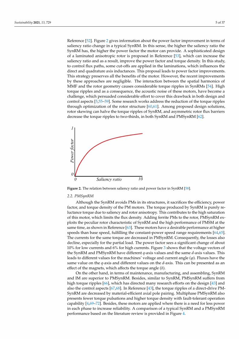
factor, and torque density of the PM motors. The torque produced by SynRM is purely reluctance torque due to saliency and rotor anisotropy. This contributes to the high satu-ration of this motor, which limits the flux density. Adding ferrite PMs to the rotor, PMSynRM exploits the peculiar rotor characteristic of SynRM and the high performance of PMSM at the same time, as shown in Reference [63]. These motors have a desirable performance at higher speeds than base speed, fulfilling the constant-power speed range requirements [64,65]. The currents for the same torque are decreased in PMSynRM. Con-sequently, the losses also decline, especially for the partial load. The power factor sees a significant change of about 10% for low currents and 6% for high currents. Figure 3 shows that the voltage vectors of the SynRM and PMSynRM have different q-axis values and the same d-axis values. This leads to different values for the machines’ voltage and current
Figure 2. The relation between saliency ratio and power factor in SynRM [58].
2.2. PMSynRM
Although the SynRM avoids PMs in its structures, it sacrifices the efficiency, powerfactor, and torque density of the PM motors. The torque produced by SynRM is purely re-luctance torque due to saliency and rotor anisotropy. This contributes to the high saturationof this motor, which limits the flux density. Adding ferrite PMs to the rotor, PMSynRM ex-ploits the peculiar rotor characteristic of SynRM and the high performance of PMSM at thesame time, as shown in Reference [63]. These motors have a desirable performance at higherspeeds than base speed, fulfilling the constant-power speed range requirements [64,65].The currents for the same torque are decreased in PMSynRM. Consequently, the losses alsodecline, especially for the partial load. The power factor sees a significant change of about10% for low currents and 6% for high currents. Figure 3 shows that the voltage vectors ofthe SynRM and PMSynRM have different q-axis values and the same d-axis values. Thisleads to different values for the machines’ voltage and current angle (ϕ). Fluxes have thesame value on the q-axis and different values on the d-axis. This can be presented as aneffect of the magnets, which affects the torque angle (δ).
On the other hand, in terms of maintenance, manufacturing, and assembling, SynRMand IM are superior to PMSynRM. Besides, similar to SynRM, PMSynRM suffers fromhigh torque ripples [66], which has directed many research efforts on the design [43] andalso the control aspects [67,68]. In Reference [43], the torque ripples of a direct-drive PM-SynRM are decreased by material-efficient axial pole pairing. Multiphase PMSynRM alsopresents fewer torque pulsations and higher torque density with fault-tolerant operationcapability [4,69–72]. Besides, these motors are applied where there is a need for less powerin each phase to increase reliability. A comparison of a typical SynRM and a PMSynRMperformance based on the literature review is provided in Figure 4.
Sustainability 2021, 13, 729 6 of 37
Sustainability 2021, 13, x FOR PEER REVIEW 6 of 38
angle (φ). Fluxes have the same value on the q-axis and different values on the d-axis. This can be presented as an effect of the magnets, which affects the torque angle (δ).
Figure 3. The vector diagram of SynRM/PMSynRM.
On the other hand, in terms of maintenance, manufacturing, and assembling, SynRM and IM are superior to PMSynRM. Besides, similar to SynRM, PMSynRM suffers from high torque ripples [66], which has directed many research efforts on the design [43] and also the control aspects [67,68]. In Reference [43], the torque ripples of a direct-drive PMSynRM are decreased by material-efficient axial pole pairing. Multiphase PMSynRM also presents fewer torque pulsations and higher torque density with fault-tolerant oper-ation capability [4,69–72]. Besides, these motors are applied where there is a need for less power in each phase to increase reliability. A comparison of a typical SynRM and a PMSynRM performance based on the literature review is provided in Figure 4.
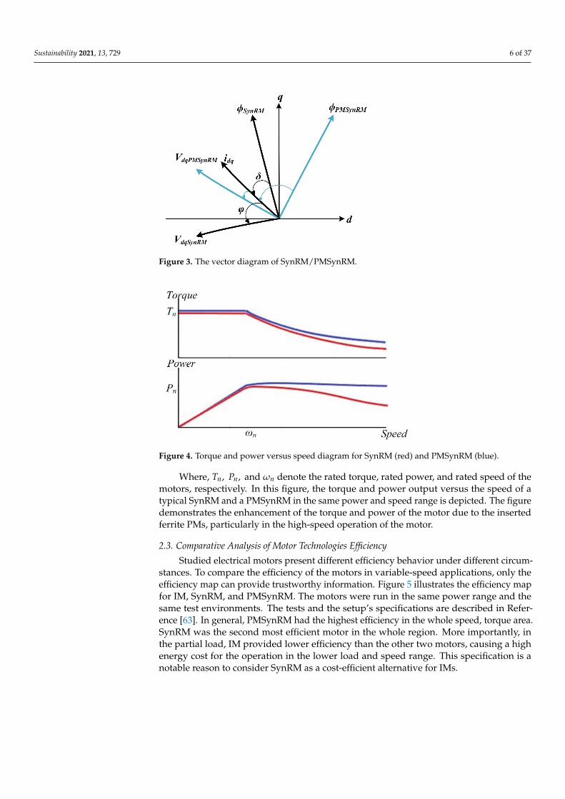
Figure 4. Torque and power versus speed diagram for SynRM (red) and PMSynRM (blue).
Where, 𝑇 , 𝑃 , and 𝜔 denote the rated torque, rated power, and rated speed of the motors, respectively. In this figure, the torque and power output versus the speed of a typical SynRM and a PMSynRM in the same power and speed range is depicted. The fig-ure demonstrates the enhancement of the torque and power of the motor due to the in-serted ferrite PMs, particularly in the high-speed operation of the motor.
2.3. Comparative Analysis of Motor Technologies Efficiency Studied electrical motors present different efficiency behavior under different cir-
cumstances. To compare the efficiency of the motors in variable-speed applications, only the efficiency map can provide trustworthy information. Figure 5 illustrates the efficiency
Figure 3. The vector diagram of SynRM/PMSynRM.
Sustainability 2021, 13, x FOR PEER REVIEW 6 of 38
angle (φ). Fluxes have the same value on the q-axis and different values on the d-axis. This can be presented as an effect of the magnets, which affects the torque angle (δ).
Figure 3. The vector diagram of SynRM/PMSynRM.
On the other hand, in terms of maintenance, manufacturing, and assembling, SynRM and IM are superior to PMSynRM. Besides, similar to SynRM, PMSynRM suffers from high torque ripples [66], which has directed many research efforts on the design [43] and also the control aspects [67,68]. In Reference [43], the torque ripples of a direct-drive PMSynRM are decreased by material-efficient axial pole pairing. Multiphase PMSynRM also presents fewer torque pulsations and higher torque density with fault-tolerant oper-ation capability [4,69–72]. Besides, these motors are applied where there is a need for less power in each phase to increase reliability. A comparison of a typical SynRM and a PMSynRM performance based on the literature review is provided in Figure 4.
Figure 4. Torque and power versus speed diagram for SynRM (red) and PMSynRM (blue).
Where, 𝑇 , 𝑃 , and 𝜔 denote the rated torque, rated power, and rated speed of the motors, respectively. In this figure, the torque and power output versus the speed of a typical SynRM and a PMSynRM in the same power and speed range is depicted. The fig-ure demonstrates the enhancement of the torque and power of the motor due to the in-serted ferrite PMs, particularly in the high-speed operation of the motor.
2.3. Comparative Analysis of Motor Technologies Efficiency Studied electrical motors present different efficiency behavior under different cir-
cumstances. To compare the efficiency of the motors in variable-speed applications, only the efficiency map can provide trustworthy information. Figure 5 illustrates the efficiency
Figure 4. Torque and power versus speed diagram for SynRM (red) and PMSynRM (blue).
Where, Tn, Pn, and ωn denote the rated torque, rated power, and rated speed of themotors, respectively. In this figure, the torque and power output versus the speed of atypical SynRM and a PMSynRM in the same power and speed range is depicted. The figuredemonstrates the enhancement of the torque and power of the motor due to the insertedferrite PMs, particularly in the high-speed operation of the motor.
2.3. Comparative Analysis of Motor Technologies Efficiency
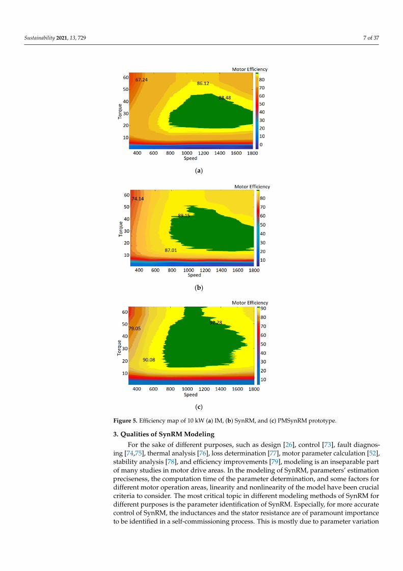
Studied electrical motors present different efficiency behavior under different circum-stances. To compare the efficiency of the motors in variable-speed applications, only theefficiency map can provide trustworthy information. Figure 5 illustrates the efficiency mapfor IM, SynRM, and PMSynRM. The motors were run in the same power range and thesame test environments. The tests and the setup’s specifications are described in Refer-ence [63]. In general, PMSynRM had the highest efficiency in the whole speed, torque area.SynRM was the second most efficient motor in the whole region. More importantly, inthe partial load, IM provided lower efficiency than the other two motors, causing a highenergy cost for the operation in the lower load and speed range. This specification is anotable reason to consider SynRM as a cost-efficient alternative for IMs.
Sustainability 2021, 13, 729 7 of 37
Sustainability 2021, 13, x FOR PEER REVIEW 7 of 38
map for IM, SynRM, and PMSynRM. The motors were run in the same power range and the same test environments. The tests and the setup’s specifications are described in Ref-erence [63]. In general, PMSynRM had the highest efficiency in the whole speed, torque area. SynRM was the second most efficient motor in the whole region. More importantly, in the partial load, IM provided lower efficiency than the other two motors, causing a high energy cost for the operation in the lower load and speed range. This specification is a notable reason to consider SynRM as a cost-efficient alternative for IMs.
(a)
(b)
(c)
Figure 5. Efficiency map of 10 kW (a) IM, (b) SynRM, and (c) PMSynRM prototype.
3. Qualities of SynRM Modeling For the sake of different purposes, such as design [26], control [73], fault diagnosing
[74,75], thermal analysis [76], loss determination [77], motor parameter calculation [52], stability analysis [78], and efficiency improvements [79], modeling is an inseparable part
Figure 5. Efficiency map of 10 kW (a) IM, (b) SynRM, and (c) PMSynRM prototype.
3. Qualities of SynRM Modeling
For the sake of different purposes, such as design [26], control [73], fault diagnos-ing [74,75], thermal analysis [76], loss determination [77], motor parameter calculation [52],stability analysis [78], and efficiency improvements [79], modeling is an inseparable partof many studies in motor drive areas. In the modeling of SynRM, parameters’ estimationpreciseness, the computation time of the parameter determination, and some factors fordifferent motor operation areas, linearity and nonlinearity of the model have been crucialcriteria to consider. The most critical topic in different modeling methods of SynRM fordifferent purposes is the parameter identification of SynRM. Especially, for more accuratecontrol of SynRM, the inductances and the stator resistance are of paramount importanceto be identified in a self-commissioning process. This is mostly due to parameter variation
Sustainability 2021, 13, 729 8 of 37
under the different thermal conditions and cross saturation of the rotor. More specifically,the inductances are considered as constant values, while these parameters are functions ofcurrents in different axes. We categorized the parameter identification into three differentgroups as follows:
1. Numerical and analytical models of SynRM2. Offline parameter identification3. Online parameter identification through an inverter
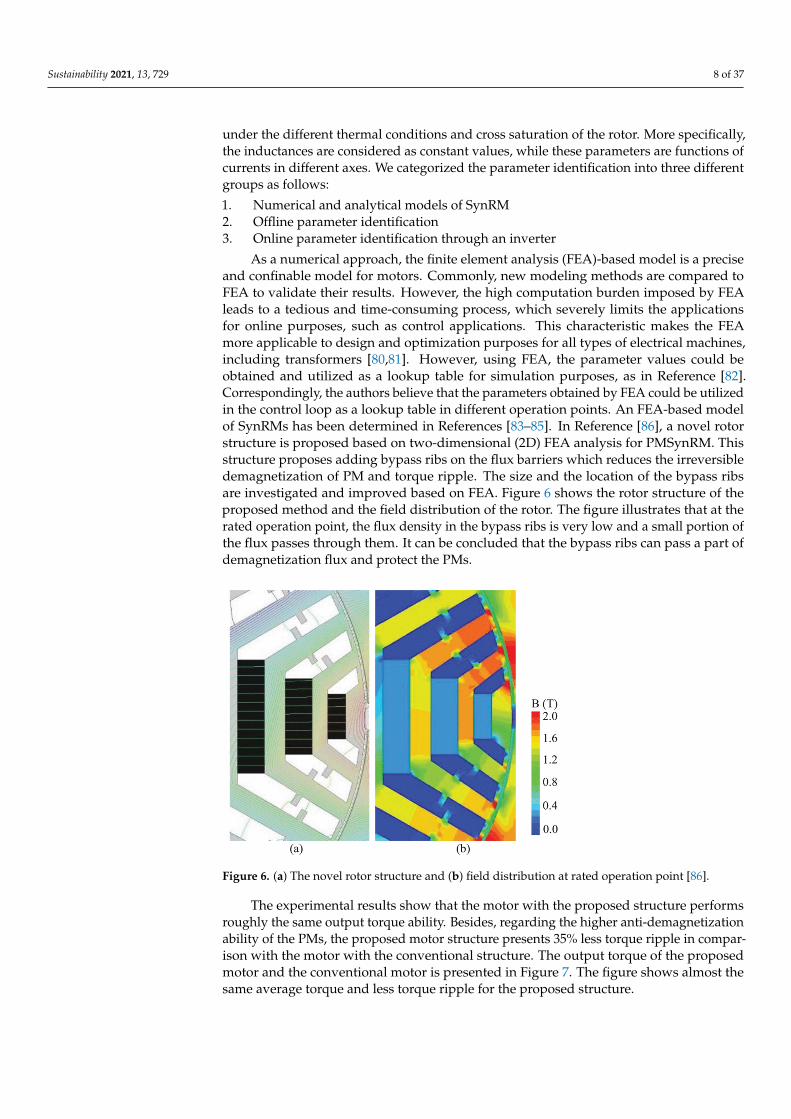
As a numerical approach, the finite element analysis (FEA)-based model is a preciseand confinable model for motors. Commonly, new modeling methods are compared toFEA to validate their results. However, the high computation burden imposed by FEAleads to a tedious and time-consuming process, which severely limits the applicationsfor online purposes, such as control applications. This characteristic makes the FEAmore applicable to design and optimization purposes for all types of electrical machines,including transformers [80,81]. However, using FEA, the parameter values could beobtained and utilized as a lookup table for simulation purposes, as in Reference [82].Correspondingly, the authors believe that the parameters obtained by FEA could be utilizedin the control loop as a lookup table in different operation points. An FEA-based modelof SynRMs has been determined in References [83–85]. In Reference [86], a novel rotorstructure is proposed based on two-dimensional (2D) FEA analysis for PMSynRM. Thisstructure proposes adding bypass ribs on the flux barriers which reduces the irreversibledemagnetization of PM and torque ripple. The size and the location of the bypass ribsare investigated and improved based on FEA. Figure 6 shows the rotor structure of theproposed method and the field distribution of the rotor. The figure illustrates that at therated operation point, the flux density in the bypass ribs is very low and a small portion ofthe flux passes through them. It can be concluded that the bypass ribs can pass a part ofdemagnetization flux and protect the PMs.
Sustainability 2021, 13, x FOR PEER REVIEW 8 of 38
of many studies in motor drive areas. In the modeling of SynRM, parameters’ estimation preciseness, the computation time of the parameter determination, and some factors for different motor operation areas, linearity and nonlinearity of the model have been crucial criteria to consider. The most critical topic in different modeling methods of SynRM for different purposes is the parameter identification of SynRM. Especially, for more accurate control of SynRM, the inductances and the stator resistance are of paramount importance to be identified in a self-commissioning process. This is mostly due to parameter variation under the different thermal conditions and cross saturation of the rotor. More specifically, the inductances are considered as constant values, while these parameters are functions of currents in different axes. We categorized the parameter identification into three differ-ent groups as follows:
1. Numerical and analytical models of SynRM 2. Offline parameter identification 3. Online parameter identification through an inverter
As a numerical approach, the finite element analysis (FEA)-based model is a precise and confinable model for motors. Commonly, new modeling methods are compared to FEA to validate their results. However, the high computation burden imposed by FEA leads to a tedious and time-consuming process, which severely limits the applications for online purposes, such as control applications. This characteristic makes the FEA more ap-plicable to design and optimization purposes for all types of electrical machines, including transformers [80,81]. However, using FEA, the parameter values could be obtained and utilized as a lookup table for simulation purposes, as in Reference [82]. Correspondingly, the authors believe that the parameters obtained by FEA could be utilized in the control loop as a lookup table in different operation points. An FEA-based model of SynRMs has been determined in References [83–85]. In Reference [86], a novel rotor structure is pro-posed based on two-dimensional (2D) FEA analysis for PMSynRM. This structure pro-poses adding bypass ribs on the flux barriers which reduces the irreversible demagneti-zation of PM and torque ripple. The size and the location of the bypass ribs are investi-gated and improved based on FEA. Figure 6 shows the rotor structure of the proposed method and the field distribution of the rotor. The figure illustrates that at the rated oper-ation point, the flux density in the bypass ribs is very low and a small portion of the flux passes through them. It can be concluded that the bypass ribs can pass a part of demag-netization flux and protect the PMs.
Figure 6. (a) The novel rotor structure and (b) field distribution at rated operation point [86]. Figure 6. (a) The novel rotor structure and (b) field distribution at rated operation point [86].
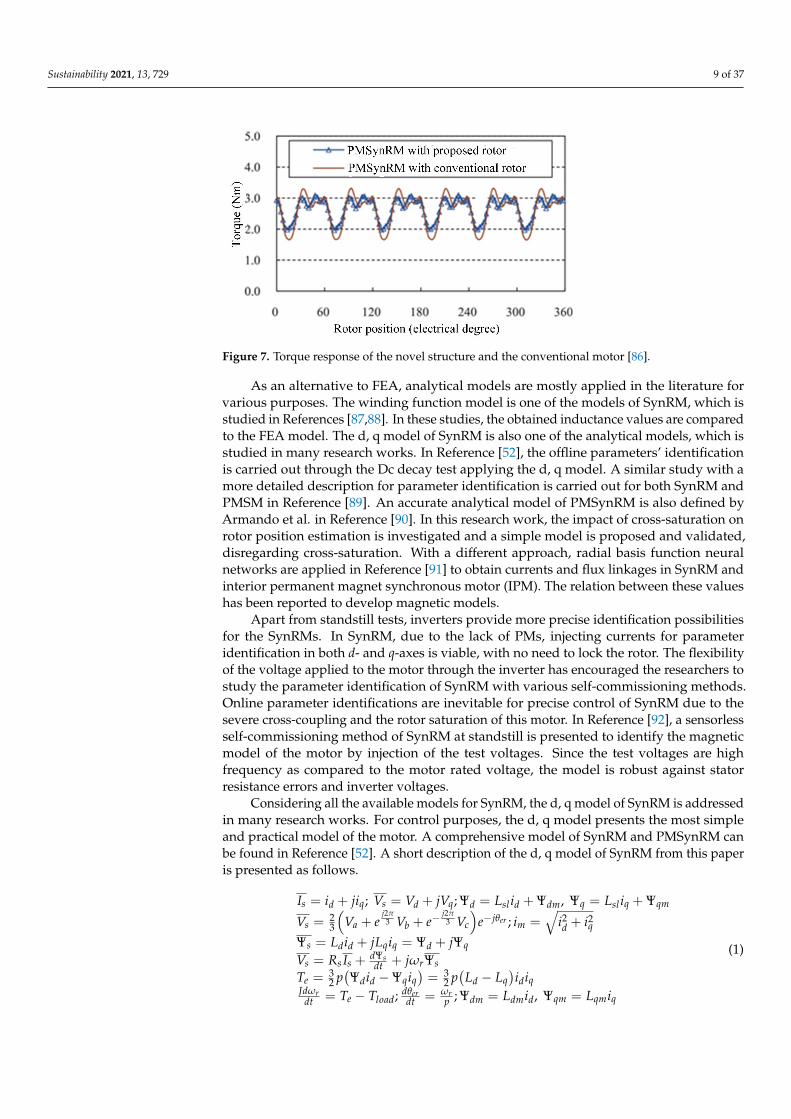
The experimental results show that the motor with the proposed structure performsroughly the same output torque ability. Besides, regarding the higher anti-demagnetizationability of the PMs, the proposed motor structure presents 35% less torque ripple in compar-ison with the motor with the conventional structure. The output torque of the proposedmotor and the conventional motor is presented in Figure 7. The figure shows almost thesame average torque and less torque ripple for the proposed structure.
Sustainability 2021, 13, 729 9 of 37
Sustainability 2021, 13, x FOR PEER REVIEW 9 of 38
The experimental results show that the motor with the proposed structure performs roughly the same output torque ability. Besides, regarding the higher anti-demagnetiza-tion ability of the PMs, the proposed motor structure presents 35% less torque ripple in comparison with the motor with the conventional structure. The output torque of the pro-posed motor and the conventional motor is presented in Figure 7. The figure shows almost the same average torque and less torque ripple for the proposed structure.
Figure 7. Torque response of the novel structure and the conventional motor [86].
As an alternative to FEA, analytical models are mostly applied in the literature for various purposes. The winding function model is one of the models of SynRM, which is studied in References [87,88]. In these studies, the obtained inductance values are com-pared to the FEA model. The d, q model of SynRM is also one of the analytical models, which is studied in many research works. In Reference [52], the offline parameters’ iden-tification is carried out through the Dc decay test applying the d, q model. A similar study with a more detailed description for parameter identification is carried out for both SynRM and PMSM in Reference [89]. An accurate analytical model of PMSynRM is also defined by Armando et al. in Reference [90]. In this research work, the impact of cross-saturation on rotor position estimation is investigated and a simple model is proposed and validated, disregarding cross-saturation. With a different approach, radial basis func-tion neural networks are applied in Reference [91] to obtain currents and flux linkages in SynRM and interior permanent magnet synchronous motor (IPM). The relation between these values has been reported to develop magnetic models.
Apart from standstill tests, inverters provide more precise identification possibilities for the SynRMs. In SynRM, due to the lack of PMs, injecting currents for parameter iden-tification in both d- and q-axes is viable, with no need to lock the rotor. The flexibility of the voltage applied to the motor through the inverter has encouraged the researchers to study the parameter identification of SynRM with various self-commissioning methods. Online parameter identifications are inevitable for precise control of SynRM due to the severe cross-coupling and the rotor saturation of this motor. In Reference [92], a sensorless self-commissioning method of SynRM at standstill is presented to identify the magnetic model of the motor by injection of the test voltages. Since the test voltages are high fre-quency as compared to the motor rated voltage, the model is robust against stator re-sistance errors and inverter voltages.
Considering all the available models for SynRM, the d, q model of SynRM is ad-dressed in many research works. For control purposes, the d, q model presents the most simple and practical model of the motor. A comprehensive model of SynRM and PMSynRM can be found in Reference [52]. A short description of the d, q model of SynRM from this paper is presented as follows. 𝐼 = 𝑖 + 𝑗𝑖 ; 𝑉 = 𝑉 + 𝑗𝑉 ; 𝛹 = 𝐿 𝑖 + 𝛹 , 𝛹 = 𝐿 𝑖 + 𝛹 (1)
Figure 7. Torque response of the novel structure and the conventional motor [86].
As an alternative to FEA, analytical models are mostly applied in the literature forvarious purposes. The winding function model is one of the models of SynRM, which isstudied in References [87,88]. In these studies, the obtained inductance values are comparedto the FEA model. The d, q model of SynRM is also one of the analytical models, which isstudied in many research works. In Reference [52], the offline parameters’ identificationis carried out through the Dc decay test applying the d, q model. A similar study with amore detailed description for parameter identification is carried out for both SynRM andPMSM in Reference [89]. An accurate analytical model of PMSynRM is also defined byArmando et al. in Reference [90]. In this research work, the impact of cross-saturation onrotor position estimation is investigated and a simple model is proposed and validated,disregarding cross-saturation. With a different approach, radial basis function neuralnetworks are applied in Reference [91] to obtain currents and flux linkages in SynRM andinterior permanent magnet synchronous motor (IPM). The relation between these valueshas been reported to develop magnetic models.
Apart from standstill tests, inverters provide more precise identification possibilitiesfor the SynRMs. In SynRM, due to the lack of PMs, injecting currents for parameteridentification in both d- and q-axes is viable, with no need to lock the rotor. The flexibilityof the voltage applied to the motor through the inverter has encouraged the researchers tostudy the parameter identification of SynRM with various self-commissioning methods.Online parameter identifications are inevitable for precise control of SynRM due to thesevere cross-coupling and the rotor saturation of this motor. In Reference [92], a sensorlessself-commissioning method of SynRM at standstill is presented to identify the magneticmodel of the motor by injection of the test voltages. Since the test voltages are highfrequency as compared to the motor rated voltage, the model is robust against statorresistance errors and inverter voltages.
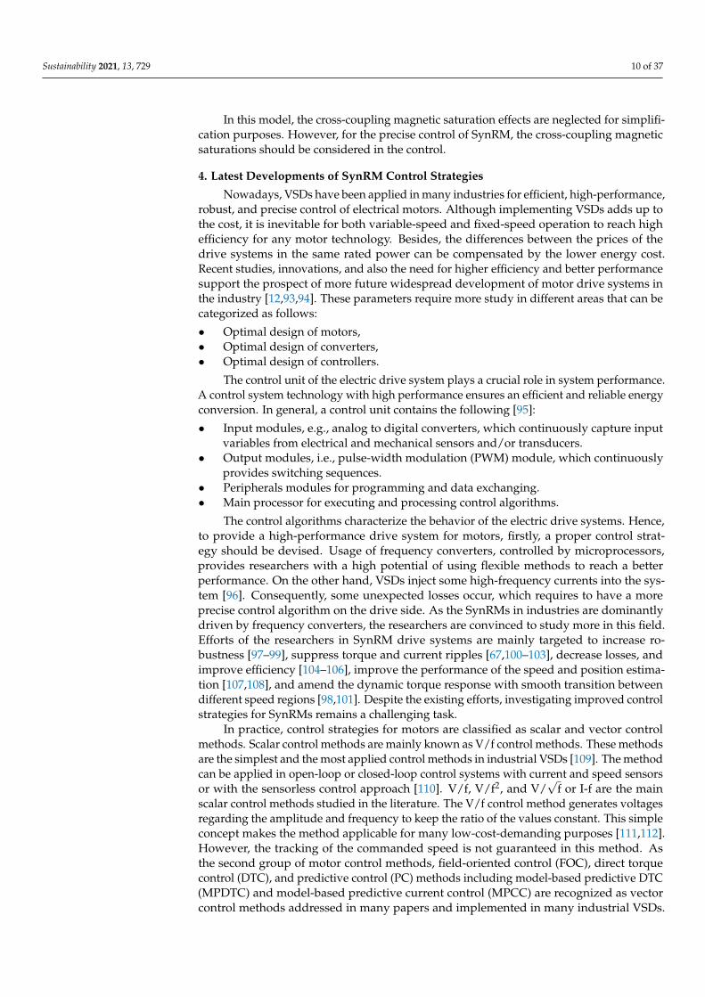
Considering all the available models for SynRM, the d, q model of SynRM is addressedin many research works. For control purposes, the d, q model presents the most simpleand practical model of the motor. A comprehensive model of SynRM and PMSynRM canbe found in Reference [52]. A short description of the d, q model of SynRM from this paperis presented as follows.
Is = id + jiq; Vs = Vd + jVq; Ψd = Lsl id + Ψdm, Ψq = Lsl iq + Ψqm
Vs =23
(Va + e
j2π3 Vb + e−
j2π3 Vc
)e−jθer ; im =
√i2d + i2q
Ψs = Ldid + jLqiq = Ψd + jΨq
Vs = Rs Is +dΨsdt + jωrΨs
Te =32 p(Ψdid −Ψqiq
)= 3
2 p(
Ld − Lq)idiq
Jdωrdt = Te − Tload; dθer
dt = ωrp ; Ψdm = Ldmid, Ψqm = Lqmiq
(1)
Sustainability 2021, 13, 729 10 of 37
In this model, the cross-coupling magnetic saturation effects are neglected for simplifi-cation purposes. However, for the precise control of SynRM, the cross-coupling magneticsaturations should be considered in the control.
4. Latest Developments of SynRM Control Strategies
Nowadays, VSDs have been applied in many industries for efficient, high-performance,robust, and precise control of electrical motors. Although implementing VSDs adds up tothe cost, it is inevitable for both variable-speed and fixed-speed operation to reach highefficiency for any motor technology. Besides, the differences between the prices of thedrive systems in the same rated power can be compensated by the lower energy cost.Recent studies, innovations, and also the need for higher efficiency and better performancesupport the prospect of more future widespread development of motor drive systems inthe industry [12,93,94]. These parameters require more study in different areas that can becategorized as follows:
• Optimal design of motors,• Optimal design of converters,• Optimal design of controllers.
The control unit of the electric drive system plays a crucial role in system performance.A control system technology with high performance ensures an efficient and reliable energyconversion. In general, a control unit contains the following [95]:
• Input modules, e.g., analog to digital converters, which continuously capture inputvariables from electrical and mechanical sensors and/or transducers.
• Output modules, i.e., pulse-width modulation (PWM) module, which continuouslyprovides switching sequences.
• Peripherals modules for programming and data exchanging.• Main processor for executing and processing control algorithms.
The control algorithms characterize the behavior of the electric drive systems. Hence,to provide a high-performance drive system for motors, firstly, a proper control strat-egy should be devised. Usage of frequency converters, controlled by microprocessors,provides researchers with a high potential of using flexible methods to reach a betterperformance. On the other hand, VSDs inject some high-frequency currents into the sys-tem [96]. Consequently, some unexpected losses occur, which requires to have a moreprecise control algorithm on the drive side. As the SynRMs in industries are dominantlydriven by frequency converters, the researchers are convinced to study more in this field.Efforts of the researchers in SynRM drive systems are mainly targeted to increase ro-bustness [97–99], suppress torque and current ripples [67,100–103], decrease losses, andimprove efficiency [104–106], improve the performance of the speed and position estima-tion [107,108], and amend the dynamic torque response with smooth transition betweendifferent speed regions [98,101]. Despite the existing efforts, investigating improved controlstrategies for SynRMs remains a challenging task.
In practice, control strategies for motors are classified as scalar and vector controlmethods. Scalar control methods are mainly known as V/f control methods. These methodsare the simplest and the most applied control methods in industrial VSDs [109]. The methodcan be applied in open-loop or closed-loop control systems with current and speed sensorsor with the sensorless control approach [110]. V/f, V/f2, and V/
√f or I-f are the main
scalar control methods studied in the literature. The V/f control method generates voltagesregarding the amplitude and frequency to keep the ratio of the values constant. This simpleconcept makes the method applicable for many low-cost-demanding purposes [111,112].However, the tracking of the commanded speed is not guaranteed in this method. Asthe second group of motor control methods, field-oriented control (FOC), direct torquecontrol (DTC), and predictive control (PC) methods including model-based predictive DTC(MPDTC) and model-based predictive current control (MPCC) are recognized as vectorcontrol methods addressed in many papers and implemented in many industrial VSDs.
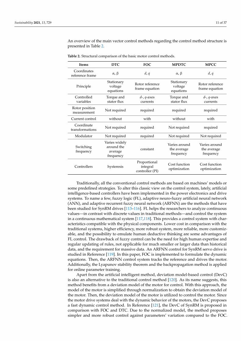
Sustainability 2021, 13, 729 11 of 37
An overview of the main vector control methods regarding the control method structure ispresented in Table 2.
Table 2. Structural comparison of the basic motor control methods.
Items DTC FOC MPDTC MPCC
Coordinatesreference frame α, β d, q α, β d, q
PrincipleStationary
voltageequations
Rotor referenceframe equation
Stationaryvoltage
equations
Rotor referenceframe equation
Controlledvariables
Torque andstator flux
d-, q-axescurrents
Torque andstator flux
d-, q-axescurrents
Rotor positionmeasurement Not required required required required
Current control without with without with
Coordinatetransformations Not required required Not required required
Modulator Not required required Not required Not required
Switchingfrequency
Varies widelyaround the
averagefrequency
constantVaries around
the averagefrequency
Varies aroundthe averagefrequency
Controllers hysteresisProportional
integralcontroller (PI)
Cost functionoptimization
Cost functionoptimization
Traditionally, all the conventional control methods are based on machines’ models orsome predefined strategies. To alter this classic view on the control system, lately, artificialintelligence-based controllers have been implemented in the power electronics and drivesystems. To name a few, fuzzy logic (FL), adaptive neuro-fuzzy artificial neural network(ANN), and adaptive recurrent fuzzy neural network (ARFNN) are the methods that havebeen studied for SynRM drives [113–116]. FL helps the researchers to analyze continuousvalues—in contrast with discrete values in traditional methods—and control the systemin a continuous mathematical system [117,118]. This provides a control system with char-acteristics compatible with the physical components. Lower cost in comparison with thetraditional systems, higher efficiency, more robust system, more reliable, more customiz-able, and the possibility to emulate human deductive thinking are some advantages ofFL control. The drawback of fuzzy control can be the need for high human expertise andregular updating of rules, not applicable for much smaller or larger data than historicaldata, and the requirement for massive data. An ARFNN control for SynRM servo drive isstudied in Reference [119]. In this paper, FOC is implemented to formulate the dynamicequations. Then, the ARFNN control system tracks the reference and drives the motor.Additionally, the Lyapunov stability theorem and the backpropagation method is appliedfor online parameter training.
Apart from the artificial intelligent method, deviation model-based control (DevC)is also an alternative to the traditional control method [120]. As its name suggests, thismethod benefits from a deviation model of the motor for control. With this approach, themodel of the motor is simplified through normalization to obtain the deviation model ofthe motor. Then, the deviation model of the motor is utilized to control the motor. Sincethe motor drive systems deal with the dynamic behavior of the motors, the DevC proposesa fast dynamic control method. In Reference [121], the DevC of SynRM is proposed incomparison with FOC and DTC. Due to the normalized model, the method proposessimpler and more robust control against parameters’ variation compared to the FOC.
Sustainability 2021, 13, 729 12 of 37
Besides, DevC presents less torque ripple, higher dynamic, and better flux regulation atstartup when compared with DTC.
In this section, the control methods are classified based on their highlighted strength.We categorized the motor control methods into scalar and vector control methods. Then,some improvements in the main control algorithms were investigated. These methodschange some parts of the main algorithm by adding or removing some extra computationfor some specific purposes. Moreover, some combinations of the main methods have alsobeen studied to benefit from some advantages of the two methods, simultaneously. Finally,the general control theories are studied. These methods are either singly applied to drivethe motors or they are utilized in the main motor control algorithms to enhance theirperformances.
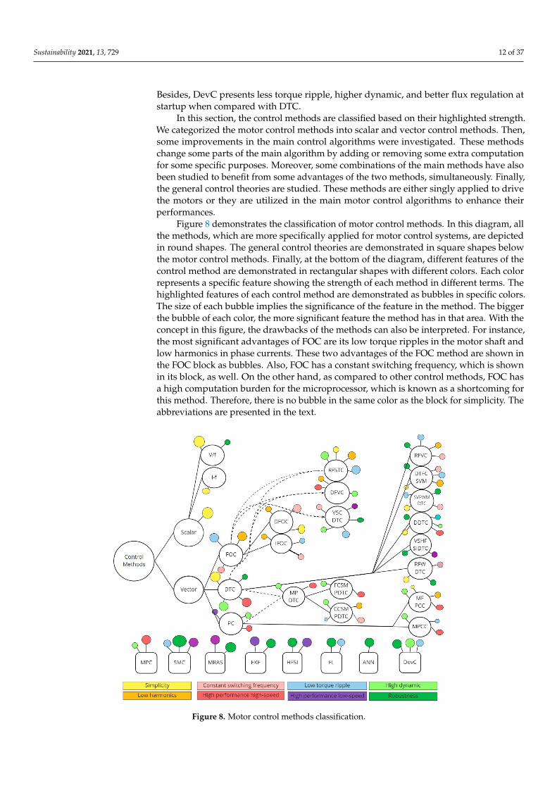
Figure 8 demonstrates the classification of motor control methods. In this diagram, allthe methods, which are more specifically applied for motor control systems, are depictedin round shapes. The general control theories are demonstrated in square shapes belowthe motor control methods. Finally, at the bottom of the diagram, different features of thecontrol method are demonstrated in rectangular shapes with different colors. Each colorrepresents a specific feature showing the strength of each method in different terms. Thehighlighted features of each control method are demonstrated as bubbles in specific colors.The size of each bubble implies the significance of the feature in the method. The biggerthe bubble of each color, the more significant feature the method has in that area. With theconcept in this figure, the drawbacks of the methods can also be interpreted. For instance,the most significant advantages of FOC are its low torque ripples in the motor shaft andlow harmonics in phase currents. These two advantages of the FOC method are shown inthe FOC block as bubbles. Also, FOC has a constant switching frequency, which is shownin its block, as well. On the other hand, as compared to other control methods, FOC hasa high computation burden for the microprocessor, which is known as a shortcoming forthis method. Therefore, there is no bubble in the same color as the block for simplicity. Theabbreviations are presented in the text.
Sustainability 2021, 13, x FOR PEER REVIEW 13 of 38
Figure 8. Motor control methods classification.
For a more detailed description of the block diagram, the features are to be discussed. As the first feature of the control methods, the simplicity of a control method denotes less computational burden on the microprocessor. Normally, complicated mathematic calcu-lations such as proportional-integral (PI) regulations lead to high execution time. Conse-quently, the cost for the microprocessor becomes high, which can make the control algo-rithm less desirable. For instance, scalar control is considered as a simple control algo-rithm due to simple calculation in the control loop. Therefore, if a simple control algorithm is looked for, scalar control can be a desirable choice. Low current harmonics is the next feature to discuss, which is considered as a strong point for a control method. In the mo-tor-drive systems, harmonic currents can be deduced from many different sources, in-cluding motors, drive systems, and the control algorithm, as well. In the literature, many research works are carried out to decrease harmonic currents. Some control methods have variable switching frequency, which is considered a weak point in many applications such as EV due to safety concerns. Variable switching frequency makes the fault diagnostic of these systems difficult using switching frequency monitoring. High performance of the method at high speeds is one of the popular topics, especially in traction applications. Proper control of the method on flux and torque is crucial at high speed. The next feature to discuss is the low torque ripple, which can lead to less acoustic noise and higher effi-ciency of the system. The operation of the control methods in low-speed regions of motors is also an important factor to consider. For instance, classic control methods do not con-sider variable references for flux, which leads to inefficient control of the motor. Besides, rotor position tracking is a challenge that motor control methods face at very low speeds. The performance of the control methods in transient mode is also crucial to pay attention to. One of the key features of control methods in transient mode is the high dynamic. The
Figure 8. Motor control methods classification.
Sustainability 2021, 13, 729 13 of 37
For a more detailed description of the block diagram, the features are to be discussed.As the first feature of the control methods, the simplicity of a control method denotesless computational burden on the microprocessor. Normally, complicated mathematiccalculations such as proportional-integral (PI) regulations lead to high execution time.Consequently, the cost for the microprocessor becomes high, which can make the controlalgorithm less desirable. For instance, scalar control is considered as a simple controlalgorithm due to simple calculation in the control loop. Therefore, if a simple controlalgorithm is looked for, scalar control can be a desirable choice. Low current harmonics isthe next feature to discuss, which is considered as a strong point for a control method. Inthe motor-drive systems, harmonic currents can be deduced from many different sources,including motors, drive systems, and the control algorithm, as well. In the literature, manyresearch works are carried out to decrease harmonic currents. Some control methods havevariable switching frequency, which is considered a weak point in many applications suchas EV due to safety concerns. Variable switching frequency makes the fault diagnosticof these systems difficult using switching frequency monitoring. High performance ofthe method at high speeds is one of the popular topics, especially in traction applications.Proper control of the method on flux and torque is crucial at high speed. The next feature todiscuss is the low torque ripple, which can lead to less acoustic noise and higher efficiencyof the system. The operation of the control methods in low-speed regions of motors isalso an important factor to consider. For instance, classic control methods do not considervariable references for flux, which leads to inefficient control of the motor. Besides, rotorposition tracking is a challenge that motor control methods face at very low speeds. Theperformance of the control methods in transient mode is also crucial to pay attention to.One of the key features of control methods in transient mode is the high dynamic. The highdynamic of a method denotes the fast response of the method to the changes in references.Robustness is the next feature that has attracted researchers’ attention in motor controlsystems. This feature in control algorithms denotes the robustness of the method againstparameter variation (e.g., stator resistance) and external disturbances (e.g., load) in drivesystems.
The rest of this section describes the main control methods and the improvements inthis area that have been recently studied in the literature.
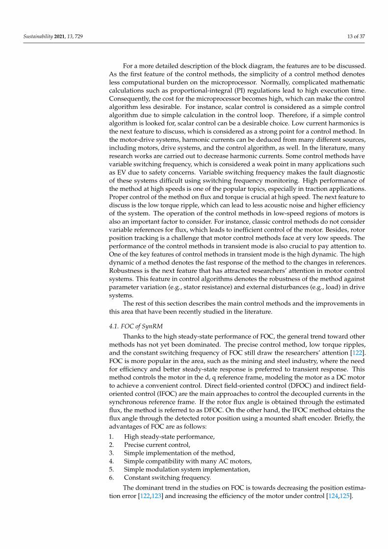
4.1. FOC of SynRM
Thanks to the high steady-state performance of FOC, the general trend toward othermethods has not yet been dominated. The precise control method, low torque ripples,and the constant switching frequency of FOC still draw the researchers’ attention [122].FOC is more popular in the area, such as the mining and steel industry, where the needfor efficiency and better steady-state response is preferred to transient response. Thismethod controls the motor in the d, q reference frame, modeling the motor as a DC motorto achieve a convenient control. Direct field-oriented control (DFOC) and indirect field-oriented control (IFOC) are the main approaches to control the decoupled currents in thesynchronous reference frame. If the rotor flux angle is obtained through the estimatedflux, the method is referred to as DFOC. On the other hand, the IFOC method obtains theflux angle through the detected rotor position using a mounted shaft encoder. Briefly, theadvantages of FOC are as follows:
1. High steady-state performance,2. Precise current control,3. Simple implementation of the method,4. Simple compatibility with many AC motors,5. Simple modulation system implementation,6. Constant switching frequency.
The dominant trend in the studies on FOC is towards decreasing the position estima-tion error [122,123] and increasing the efficiency of the motor under control [124,125].
Sustainability 2021, 13, 729 14 of 37
Regarding all the benefits of FOC, some severe drawbacks of this method convince theresearchers to study and implement other control methods. Firstly, the method is highlycomplicated from the point of the processor view. Due to the usage of the PI controller andpulse-width modulation (PWM) modulator, the FOC execution time is high and dynamicperformance is considerably low, compared to other methods. This is mostly due to thecurrent control and the modulation system that FOC applies in its control loop. Thedrawbacks of FOC can be named as follows:
1. High computational burden on the processor due to the current control and modula-tion method.
2. Low dynamic of the method due to the lack of direct control on the torque.3. Low robustness of the method due to the high dependency of the method to the
motor’s parameters (flux vector angle).
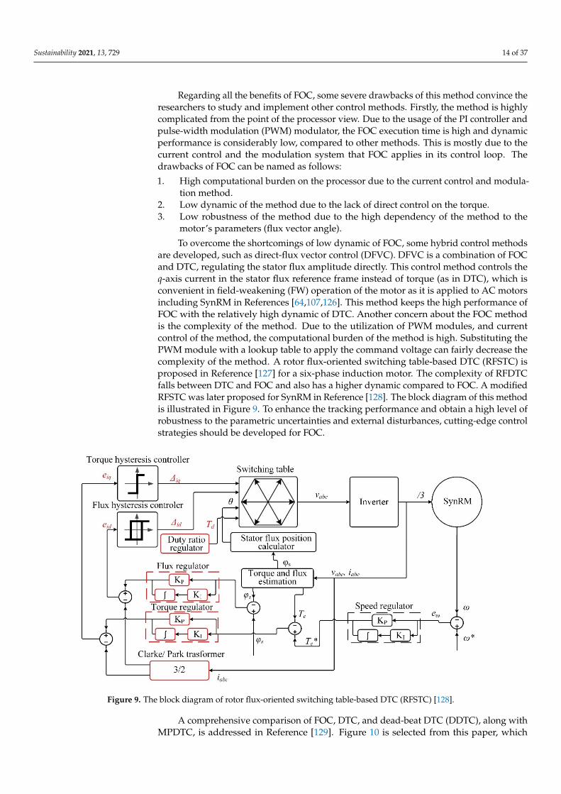
To overcome the shortcomings of low dynamic of FOC, some hybrid control methodsare developed, such as direct-flux vector control (DFVC). DFVC is a combination of FOCand DTC, regulating the stator flux amplitude directly. This control method controls theq-axis current in the stator flux reference frame instead of torque (as in DTC), which isconvenient in field-weakening (FW) operation of the motor as it is applied to AC motorsincluding SynRM in References [64,107,126]. This method keeps the high performance ofFOC with the relatively high dynamic of DTC. Another concern about the FOC methodis the complexity of the method. Due to the utilization of PWM modules, and currentcontrol of the method, the computational burden of the method is high. Substituting thePWM module with a lookup table to apply the command voltage can fairly decrease thecomplexity of the method. A rotor flux-oriented switching table-based DTC (RFSTC) isproposed in Reference [127] for a six-phase induction motor. The complexity of RFDTCfalls between DTC and FOC and also has a higher dynamic compared to FOC. A modifiedRFSTC was later proposed for SynRM in Reference [128]. The block diagram of this methodis illustrated in Figure 9. To enhance the tracking performance and obtain a high level ofrobustness to the parametric uncertainties and external disturbances, cutting-edge controlstrategies should be developed for FOC.
Sustainability 2021, 13, x FOR PEER REVIEW 15 of 38
plexity of the method. A rotor flux-oriented switching table-based DTC (RFSTC) is pro-posed in Reference [127] for a six-phase induction motor. The complexity of RFDTC falls between DTC and FOC and also has a higher dynamic compared to FOC. A modified RFSTC was later proposed for SynRM in Reference [128]. The block diagram of this method is illustrated in Figure 9. To enhance the tracking performance and obtain a high level of robustness to the parametric uncertainties and external disturbances, cutting-edge control strategies should be developed for FOC.
Figure 9. The block diagram of rotor flux-oriented switching table-based DTC (RFSTC) [128].
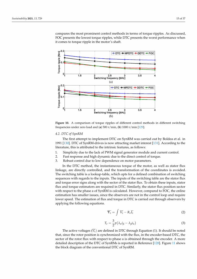
A comprehensive comparison of FOC, DTC, and dead-beat DTC (DDTC), along with MPDTC, is addressed in Reference [129]. Figure 10 is selected from this paper, which com-pares the most prominent control methods in terms of torque ripples. As discussed, FOC presents the lowest torque ripples, while DTC presents the worst performance when it comes to torque ripple in the motor’s shaft.
Figure 10. A comparison of torque ripples of different control methods in different switching fre-quencies under zero load and (a) 500 r/min, (b) 1000 r/min [129].
Figure 9. The block diagram of rotor flux-oriented switching table-based DTC (RFSTC) [128].
A comprehensive comparison of FOC, DTC, and dead-beat DTC (DDTC), along withMPDTC, is addressed in Reference [129]. Figure 10 is selected from this paper, which
Sustainability 2021, 13, 729 15 of 37
compares the most prominent control methods in terms of torque ripples. As discussed,FOC presents the lowest torque ripples, while DTC presents the worst performance whenit comes to torque ripple in the motor’s shaft.
Sustainability 2021, 13, x FOR PEER REVIEW 15 of 38
plexity of the method. A rotor flux-oriented switching table-based DTC (RFSTC) is pro-posed in Reference [127] for a six-phase induction motor. The complexity of RFDTC falls between DTC and FOC and also has a higher dynamic compared to FOC. A modified RFSTC was later proposed for SynRM in Reference [128]. The block diagram of this method is illustrated in Figure 9. To enhance the tracking performance and obtain a high level of robustness to the parametric uncertainties and external disturbances, cutting-edge control strategies should be developed for FOC.
Figure 9. The block diagram of rotor flux-oriented switching table-based DTC (RFSTC) [128].
A comprehensive comparison of FOC, DTC, and dead-beat DTC (DDTC), along with MPDTC, is addressed in Reference [129]. Figure 10 is selected from this paper, which com-pares the most prominent control methods in terms of torque ripples. As discussed, FOC presents the lowest torque ripples, while DTC presents the worst performance when it comes to torque ripple in the motor’s shaft.
Figure 10. A comparison of torque ripples of different control methods in different switching fre-quencies under zero load and (a) 500 r/min, (b) 1000 r/min [129].
Figure 10. A comparison of torque ripples of different control methods in different switchingfrequencies under zero load and (a) 500 r/min, (b) 1000 r/min [129].
4.2. DTC of SynRM
The first attempt to implement DTC on SynRM was carried out by Boldea et al. in1991 [130]. DTC of SynRM-drives is now attracting market interest [131]. According to theliterature, this is attributed to the intrinsic features, as follows:
1. Simplicity due to the lack of PWM signal generator module and current control.2. Fast response and high dynamic due to the direct control of torque.3. Robust control due to low dependence on motor parameters.
In the DTC method, the instantaneous torque of the motor, as well as stator fluxlinkage, are directly controlled, and the transformation of the coordinates is avoided.The switching table is a lookup-table, which opts for a defined combination of switchingsequences with regards to the inputs. The inputs of the switching table are the stator fluxand torque error signs along with the sector of the stator flux. To obtain these inputs, statorflux and torque estimators are required in DTC. Similarly, the stator flux position sectorwith respect to the phase a of SynRM is calculated. However, compared to FOC, the onlineestimation has smaller issues, since the observers are not in the control loop and requirelower speed. The estimation of flux and torque in DTC is carried out through observers byapplying the following equations.
Ψs =∫
Vs − Rs Is (2)
Te =32
p(λαiβ − λβiα
)(3)
The active voltages (Vs) are defined in DTC through Equation (1). It should be notedthat, since the rotor position is synchronized with the flux, in the encoder-based DTC, thesector of the rotor flux with respect to phase a is obtained through the encoder. A moredetailed description of the DTC of SynRMs is reported in Reference [128]. Figure 11 showsthe block diagram of the conventional DTC of SynRM.
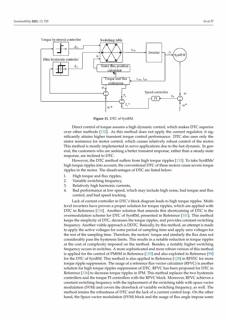
Sustainability 2021, 13, 729 16 of 37
Sustainability 2021, 13, x FOR PEER REVIEW 16 of 38
4.2. DTC of SynRM The first attempt to implement DTC on SynRM was carried out by Boldea et al. in
1991 [130]. DTC of SynRM-drives is now attracting market interest [131]. According to the literature, this is attributed to the intrinsic features, as follows:
1. Simplicity due to the lack of PWM signal generator module and current control. 2. Fast response and high dynamic due to the direct control of torque. 3. Robust control due to low dependence on motor parameters.
In the DTC method, the instantaneous torque of the motor, as well as stator flux link-age, are directly controlled, and the transformation of the coordinates is avoided. The switching table is a lookup-table, which opts for a defined combination of switching se-quences with regards to the inputs. The inputs of the switching table are the stator flux and torque error signs along with the sector of the stator flux. To obtain these inputs, stator flux and torque estimators are required in DTC. Similarly, the stator flux position sector with respect to the phase a of SynRM is calculated. However, compared to FOC, the online estimation has smaller issues, since the observers are not in the control loop and require lower speed. The estimation of flux and torque in DTC is carried out through observers by applying the following equations. 𝛹 = 𝑉 − 𝑅 𝐼 (2)
𝑇 = 32 𝑝(𝜆 𝑖 − 𝜆 𝑖 ) (3)
The active voltages (𝑉 ) are defined in DTC through Equation (1). It should be noted that, since the rotor position is synchronized with the flux, in the encoder-based DTC, the sector of the rotor flux with respect to phase a is obtained through the encoder. A more detailed description of the DTC of SynRMs is reported in Reference [128]. Figure 11 shows the block diagram of the conventional DTC of SynRM.
Figure 11. DTC of SynRM.
Direct control of torque assures a high dynamic control, which makes DTC superior over other methods [132]. As this method does not apply the current regulator, it signifi-cantly attains higher transient torque control performance. DTC also uses only the stator resistance for motor control, which causes relatively robust control of the motor. This method is mostly implemented in servo applications due to the fast dynamic. In general, the customers who are seeking a better transient response, rather than a steady-state re-sponse, are inclined to DTC.
Figure 11. DTC of SynRM.
Direct control of torque assures a high dynamic control, which makes DTC superiorover other methods [132]. As this method does not apply the current regulator, it sig-nificantly attains higher transient torque control performance. DTC also uses only thestator resistance for motor control, which causes relatively robust control of the motor.This method is mostly implemented in servo applications due to the fast dynamic. In gen-eral, the customers who are seeking a better transient response, rather than a steady-stateresponse, are inclined to DTC.
However, the DTC method suffers from high torque ripples [133]. To take SynRMs’high torque ripples into account, the conventional DTC of these motors cause severe torqueripples in the motor. The disadvantages of DTC are listed below:
1. High torque and flux ripples,2. Variable switching frequency,3. Relatively high harmonic currents,4. Bad performance at low speed, which may include high noise, bad torque and flux
control, and bad speed tracking.
Lack of current controller in DTC’s block diagram leads to high torque ripples. Multi-level inverters have proven a proper solution for torque ripples, which are applied withDTC in Reference [134]. Another solution that amends this shortcoming of DTC is theovermodulation scheme for DTC of SynRM, presented in Reference [101]. This methodkeeps the simplicity of DTC, decreases the torque ripples, and provides constant switchingfrequency. Another viable approach is DDTC. Basically, by this method, an attempt is madeto apply the active voltages for some period of sampling time and apply zero voltages forthe rest of the sampling time. Therefore, the motors’ torque and similarly the flux does notconsiderably pass the hysteresis limits. This results in a notable reduction in torque ripplesat the cost of complexity imposed on the method. Besides, a notably higher switchingfrequency occurs in switches. A more sophisticated and more robust version of this methodis applied for the control of PMSM in Reference [135] and also exploited in Reference [98]for the DTC of SynRM. This method is also applied in Reference [128] in RFSTC for moretorque ripple suppression. The usage of a reference flux-vector calculator (RFVC) is anothersolution for high torque ripples suppression of DTC. RFVC has been proposed for DTC inReference [136] to decrease torque ripples in IPM. This method replaces the two hysteresiscontrollers and the torque PI controllers with the RFVC block. Moreover, RFVC achieves aconstant switching frequency with the replacement of the switching table with space vectormodulation (SVM) and covers the drawback of variable switching frequency, as well. Themethod retains the robustness of DTC and the lack of a current control loop. On the otherhand, the Space vector modulation (SVM) block and the usage of flux angle impose some
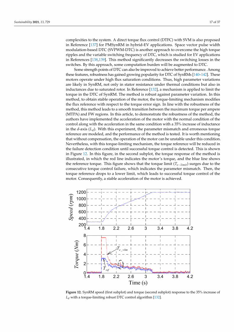
Sustainability 2021, 13, 729 17 of 37
complexities to the system. A direct torque flux control (DTFC) with SVM is also proposedin Reference [137] for PMSynRM in hybrid-EV applications. Space vector pulse widthmodulation-based DTC (SVPWM-DTC) is another approach to overcome the high torqueripples and the variable switching frequency of DTC, which is studied for EV applicationsin References [138,139]. This method significantly decreases the switching losses in theswitches. By this approach, some computation burden will be augmented to DTC.
Some strength points of DTC can also be improved to achieve better performance. Amongthese features, robustness has gained growing popularity for DTC of SynRMs [140–142]. Thesemotors operate under high flux saturation conditions. Thus, high parameter variationsare likely in SynRM, not only in stator resistance under thermal conditions but also ininductances due to saturated rotor. In Reference [132], a mechanism is applied to limit thetorque in the DTC of SynRM. The method is robust against parameter variation. In thismethod, to obtain stable operation of the motor, the torque-limiting mechanism modifiesthe flux reference with respect to the torque error sign. In line with the robustness of themethod, this method leads to a smooth transition between the maximum torque per ampere(MTPA) and FW regions. In this article, to demonstrate the robustness of the method, theauthors have implemented the acceleration of the motor with the normal condition of thecontrol along with the acceleration in the same condition with a 35% increase of inductancein the d-axis (Ld). With this experiment, the parameter mismatch and erroneous torquereference are modeled, and the performance of the method is tested. It is worth mentioningthat without compensation, the operation of the motor can be unstable under this condition.Nevertheless, with this torque-limiting mechanism, the torque reference will be reduced inthe failure detection condition until successful torque control is detected. This is shownin Figure 12. In this figure, in the second subplot, the torque response of the method isillustrated, in which the red line indicates the motor’s torque, and the blue line showsthe reference torque. This figure shows that the torque limit (Te−limit) surges due to theconsecutive torque control failure, which indicates the parameter mismatch. Then, thetorque reference drops to a lower limit, which leads to successful torque control of themotor. Consequently, a stable acceleration of the motor is achieved.
Sustainability 2021, 13, x FOR PEER REVIEW 18 of 38
is detected. This is shown in Figure 12. In this figure, in the second subplot, the torque response of the method is illustrated, in which the red line indicates the motor’s torque, and the blue line shows the reference torque. This figure shows that the torque limit (𝑇 ) surges due to the consecutive torque control failure, which indicates the param-eter mismatch. Then, the torque reference drops to a lower limit, which leads to successful torque control of the motor. Consequently, a stable acceleration of the motor is achieved.
Figure 12. SynRM speed (first subplot) and torque (second subplot) response to the 35% increase of 𝑳𝒅 with a torque-limiting robust DTC control algorithm [132].
Sliding mode control (SMC) is also one of the main approaches to increase the ro-bustness of DTC. This method is mainly applied for torque and flux estimations in DTC. SMC is applied for DTC of SynRM in Reference [143]. In this paper, the robustness against stator resistance variation is achieved through an online detection with a simple observer. This observer exploits SMC in the variable structure control-based DTC (VSC-DTC) for the objective of robustness. In this method, the constant switching frequency is also achieved through the SVM block and the torque ripples are also decreased because of stator-flux field-oriented referenced PI controllers. The simplicity of the DTC has been deteriorated instead, although the high dynamic of the method is guaranteed. From an-other angle of view, it is alleged in Reference [120] that less parameter dependency can be achieved by replacing the commonly used PI controller with a normalized deviation model of SynRM. The results for this claim validate the performance of the method and the proposed approach can increase the VSD’s robustness.
Limited performance of DTC at low speed, such as reduced torque and flux control-lability, and consequently, high noise due to the high torque ripples, are concerned in many research works [144,145]. Sensorless DTC is one of the solutions, estimating the ro-tor position and speed with different strategies. The high-frequency (HF) signal injection (HFSI) is one of the most popular methods. These methods are reliable and have a desir-able performance at low speed, particularly at the standstill. Even though, the resonance and extra losses are notable drawbacks of this method, which limits their utilization, es-pecially at medium and high speeds. Sayeef et al. have addressed the HFSI in References [146,147] at low speed, including standstill, to obtain the rotor position and speed. Refer-ence [146] discusses the variable structure control, using HFSI (VSHFSI-DTC) at very low
Figure 12. SynRM speed (first subplot) and torque (second subplot) response to the 35% increase ofLd with a torque-limiting robust DTC control algorithm [132].
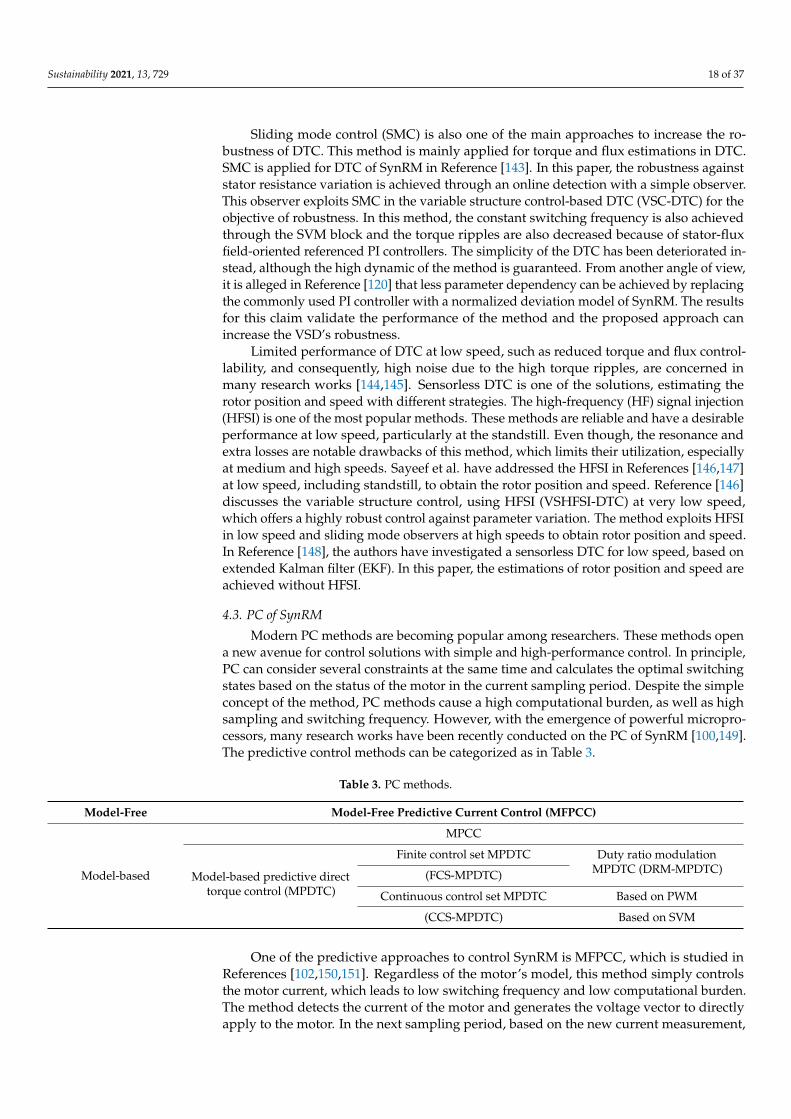
Sustainability 2021, 13, 729 18 of 37
Sliding mode control (SMC) is also one of the main approaches to increase the ro-bustness of DTC. This method is mainly applied for torque and flux estimations in DTC.SMC is applied for DTC of SynRM in Reference [143]. In this paper, the robustness againststator resistance variation is achieved through an online detection with a simple observer.This observer exploits SMC in the variable structure control-based DTC (VSC-DTC) for theobjective of robustness. In this method, the constant switching frequency is also achievedthrough the SVM block and the torque ripples are also decreased because of stator-fluxfield-oriented referenced PI controllers. The simplicity of the DTC has been deteriorated in-stead, although the high dynamic of the method is guaranteed. From another angle of view,it is alleged in Reference [120] that less parameter dependency can be achieved by replacingthe commonly used PI controller with a normalized deviation model of SynRM. The resultsfor this claim validate the performance of the method and the proposed approach canincrease the VSD’s robustness.
Limited performance of DTC at low speed, such as reduced torque and flux control-lability, and consequently, high noise due to the high torque ripples, are concerned inmany research works [144,145]. Sensorless DTC is one of the solutions, estimating therotor position and speed with different strategies. The high-frequency (HF) signal injection(HFSI) is one of the most popular methods. These methods are reliable and have a desirableperformance at low speed, particularly at the standstill. Even though, the resonance andextra losses are notable drawbacks of this method, which limits their utilization, especiallyat medium and high speeds. Sayeef et al. have addressed the HFSI in References [146,147]at low speed, including standstill, to obtain the rotor position and speed. Reference [146]discusses the variable structure control, using HFSI (VSHFSI-DTC) at very low speed,which offers a highly robust control against parameter variation. The method exploits HFSIin low speed and sliding mode observers at high speeds to obtain rotor position and speed.In Reference [148], the authors have investigated a sensorless DTC for low speed, based onextended Kalman filter (EKF). In this paper, the estimations of rotor position and speed areachieved without HFSI.
4.3. PC of SynRM
Modern PC methods are becoming popular among researchers. These methods opena new avenue for control solutions with simple and high-performance control. In principle,PC can consider several constraints at the same time and calculates the optimal switchingstates based on the status of the motor in the current sampling period. Despite the simpleconcept of the method, PC methods cause a high computational burden, as well as highsampling and switching frequency. However, with the emergence of powerful micropro-cessors, many research works have been recently conducted on the PC of SynRM [100,149].The predictive control methods can be categorized as in Table 3.
Table 3. PC methods.
Model-Free Model-Free Predictive Current Control (MFPCC)
Model-based
MPCC
Model-based predictive directtorque control (MPDTC)
Finite control set MPDTC Duty ratio modulationMPDTC (DRM-MPDTC)(FCS-MPDTC)
Continuous control set MPDTC Based on PWM
(CCS-MPDTC) Based on SVM
One of the predictive approaches to control SynRM is MFPCC, which is studied inReferences [102,150,151]. Regardless of the motor’s model, this method simply controlsthe motor current, which leads to low switching frequency and low computational burden.The method detects the current of the motor and generates the voltage vector to directlyapply to the motor. In the next sampling period, based on the new current measurement,
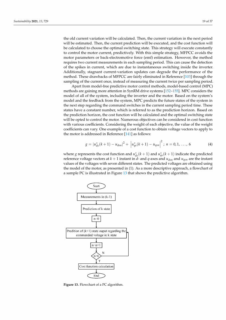
Sustainability 2021, 13, 729 19 of 37
the old current variation will be calculated. Then, the current variation in the next periodwill be estimated. Then, the current prediction will be executed, and the cost function willbe calculated to choose the optimal switching state. This strategy will execute constantlyto control the motor current, predictively. With this simple strategy, MFPCC avoids themotor parameters or back-electromotive force (emf) estimation. However, the methodrequires two current measurements in each sampling period. This can cause the detectionof the spikes in current, which are due to instantaneous switching inside the inverter.Additionally, stagnant current-variation updates can degrade the performance of themethod. These drawbacks of MFPCC are fairly eliminated in Reference [103] through thesampling of the current once, instead of measuring the current twice per sampling period.
Apart from model-free predictive motor control methods, model-based control (MPC)methods are gaining more attention in SynRM drive systems [152–155]. MPC considers themodel of all of the system, including the inverter and the motor. Based on the system’smodel and the feedback from the system, MPC predicts the future states of the system inthe next step regarding the command switches in the current sampling period time. Thesestates have a constant number, which is referred to as the prediction horizon. Based onthe prediction horizon, the cost function will be calculated and the optimal switching statewill be opted to control the motor. Numerous objectives can be considered in cost functionwith various coefficients. Considering the weight of each objective, the value of the weightcoefficients can vary. One example of a cost function to obtain voltage vectors to apply tothe motor is addressed in Reference [141] as follows:
g = |u∗ds(k + 1)− udsn|2 +∣∣∣u∗qs(k + 1)− uqsn
∣∣∣2 ; n = 0, 1, . . . , 6 (4)
where g represents the cost function and u∗ds(k + 1) and u∗qs(k + 1) indicate the predictedreference voltage vectors at k + 1 instant in d- and q-axes and udsn and uqsn are the instantvalues of the voltages with seven different states. The predicted voltages are obtained usingthe model of the motor, as presented in (1). As a more descriptive approach, a flowchart ofa sample PC is illustrated in Figure 13 that shows the predictive algorithm.
Sustainability 2021, 13, x FOR PEER REVIEW 21 of 38
Figure 13. Flowchart of a PC algorithm.
Figure 14. Block diagram of MPDTC of SynRM.
5. Control Strategies for Different Speed Regions of SynRM Drives At different motor speeds, some constraints limit the performance of the control
methods. The problem of tracking the speed and positioning by an encoder and low cur-rent requirement to drive in low speed and the voltage requisites at high speed are just some of the issues. At very low speeds, sensorless controls have gained attention [160,161]. In speeds up to nominal speeds, researchers mostly focus on maximum torque per ampere (MTPA) operation [162,163], while in speeds higher than nominal speed, FW is considered as a dominant approach for control [97,164] and MTPV has been implemented in speeds higher than crossover speed [165,166]. Generally, in SynRMs, the copper losses are domi-nant [51]. Thus, in terms of control, a dynamic flux reference should be determined, in-stead of a constant reference, to reach the lowest current magnitude to minimize the cop-per losses. This strategy allows the motor to deliver maximum electromagnetic torque with lower copper losses, leading to the higher overall efficiency of the drive. However, exploiting different approaches for each trajectory requires a smooth transition in be-tween.
The control strategies in different speed regions are discussed in the rest of this sec-tion. Section 5.1 investigates the research works at standstill and very low-speed control of SynRM and analyzes the challenges and the advancements to cover them. A review of the speed range of up to base speed and a review of high-speed and critical speed control
Figure 13. Flowchart of a PC algorithm.
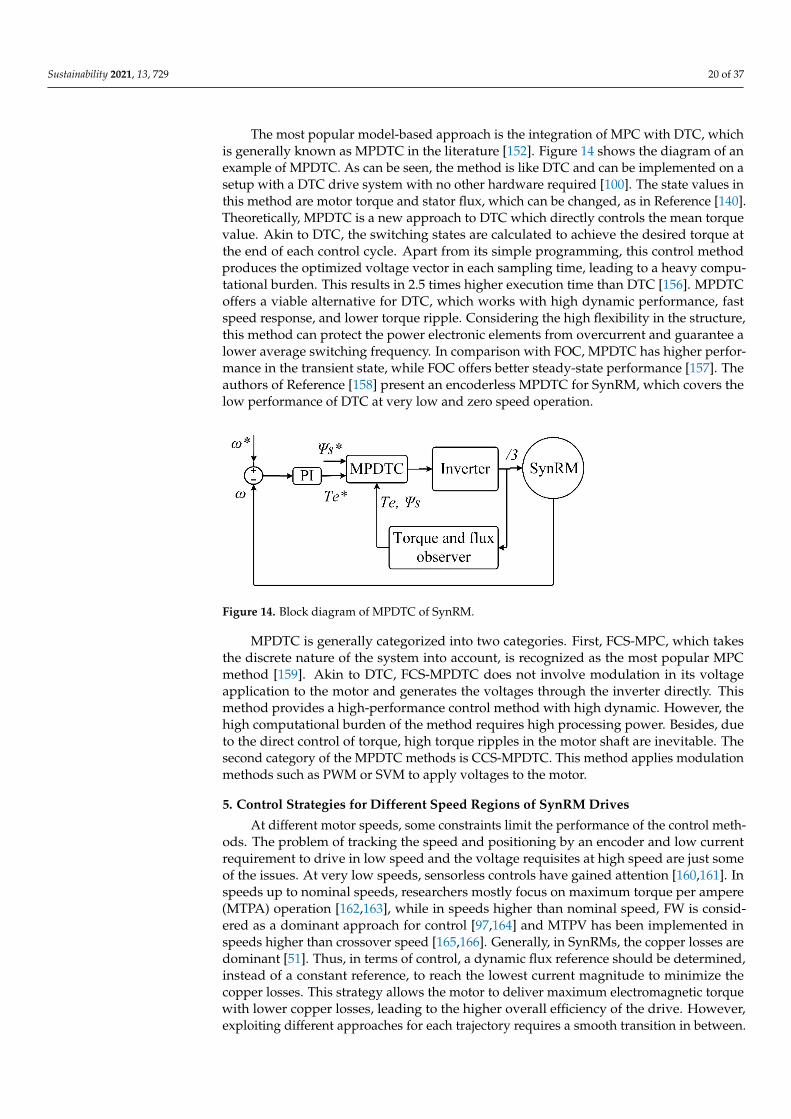
Sustainability 2021, 13, 729 20 of 37
The most popular model-based approach is the integration of MPC with DTC, whichis generally known as MPDTC in the literature [152]. Figure 14 shows the diagram of anexample of MPDTC. As can be seen, the method is like DTC and can be implemented on asetup with a DTC drive system with no other hardware required [100]. The state values inthis method are motor torque and stator flux, which can be changed, as in Reference [140].Theoretically, MPDTC is a new approach to DTC which directly controls the mean torquevalue. Akin to DTC, the switching states are calculated to achieve the desired torque atthe end of each control cycle. Apart from its simple programming, this control methodproduces the optimized voltage vector in each sampling time, leading to a heavy compu-tational burden. This results in 2.5 times higher execution time than DTC [156]. MPDTCoffers a viable alternative for DTC, which works with high dynamic performance, fastspeed response, and lower torque ripple. Considering the high flexibility in the structure,this method can protect the power electronic elements from overcurrent and guarantee alower average switching frequency. In comparison with FOC, MPDTC has higher perfor-mance in the transient state, while FOC offers better steady-state performance [157]. Theauthors of Reference [158] present an encoderless MPDTC for SynRM, which covers thelow performance of DTC at very low and zero speed operation.
Sustainability 2021, 13, x FOR PEER REVIEW 21 of 38
Figure 13. Flowchart of a PC algorithm.
Figure 14. Block diagram of MPDTC of SynRM.
5. Control Strategies for Different Speed Regions of SynRM Drives At different motor speeds, some constraints limit the performance of the control
methods. The problem of tracking the speed and positioning by an encoder and low cur-rent requirement to drive in low speed and the voltage requisites at high speed are just some of the issues. At very low speeds, sensorless controls have gained attention [160,161]. In speeds up to nominal speeds, researchers mostly focus on maximum torque per ampere (MTPA) operation [162,163], while in speeds higher than nominal speed, FW is considered as a dominant approach for control [97,164] and MTPV has been implemented in speeds higher than crossover speed [165,166]. Generally, in SynRMs, the copper losses are domi-nant [51]. Thus, in terms of control, a dynamic flux reference should be determined, in-stead of a constant reference, to reach the lowest current magnitude to minimize the cop-per losses. This strategy allows the motor to deliver maximum electromagnetic torque with lower copper losses, leading to the higher overall efficiency of the drive. However, exploiting different approaches for each trajectory requires a smooth transition in be-tween.
The control strategies in different speed regions are discussed in the rest of this sec-tion. Section 5.1 investigates the research works at standstill and very low-speed control of SynRM and analyzes the challenges and the advancements to cover them. A review of the speed range of up to base speed and a review of high-speed and critical speed control
Figure 14. Block diagram of MPDTC of SynRM.
MPDTC is generally categorized into two categories. First, FCS-MPC, which takesthe discrete nature of the system into account, is recognized as the most popular MPCmethod [159]. Akin to DTC, FCS-MPDTC does not involve modulation in its voltageapplication to the motor and generates the voltages through the inverter directly. Thismethod provides a high-performance control method with high dynamic. However, thehigh computational burden of the method requires high processing power. Besides, dueto the direct control of torque, high torque ripples in the motor shaft are inevitable. Thesecond category of the MPDTC methods is CCS-MPDTC. This method applies modulationmethods such as PWM or SVM to apply voltages to the motor.
5. Control Strategies for Different Speed Regions of SynRM Drives
At different motor speeds, some constraints limit the performance of the control meth-ods. The problem of tracking the speed and positioning by an encoder and low currentrequirement to drive in low speed and the voltage requisites at high speed are just someof the issues. At very low speeds, sensorless controls have gained attention [160,161]. Inspeeds up to nominal speeds, researchers mostly focus on maximum torque per ampere(MTPA) operation [162,163], while in speeds higher than nominal speed, FW is consid-ered as a dominant approach for control [97,164] and MTPV has been implemented inspeeds higher than crossover speed [165,166]. Generally, in SynRMs, the copper losses aredominant [51]. Thus, in terms of control, a dynamic flux reference should be determined,instead of a constant reference, to reach the lowest current magnitude to minimize thecopper losses. This strategy allows the motor to deliver maximum electromagnetic torquewith lower copper losses, leading to the higher overall efficiency of the drive. However,exploiting different approaches for each trajectory requires a smooth transition in between.
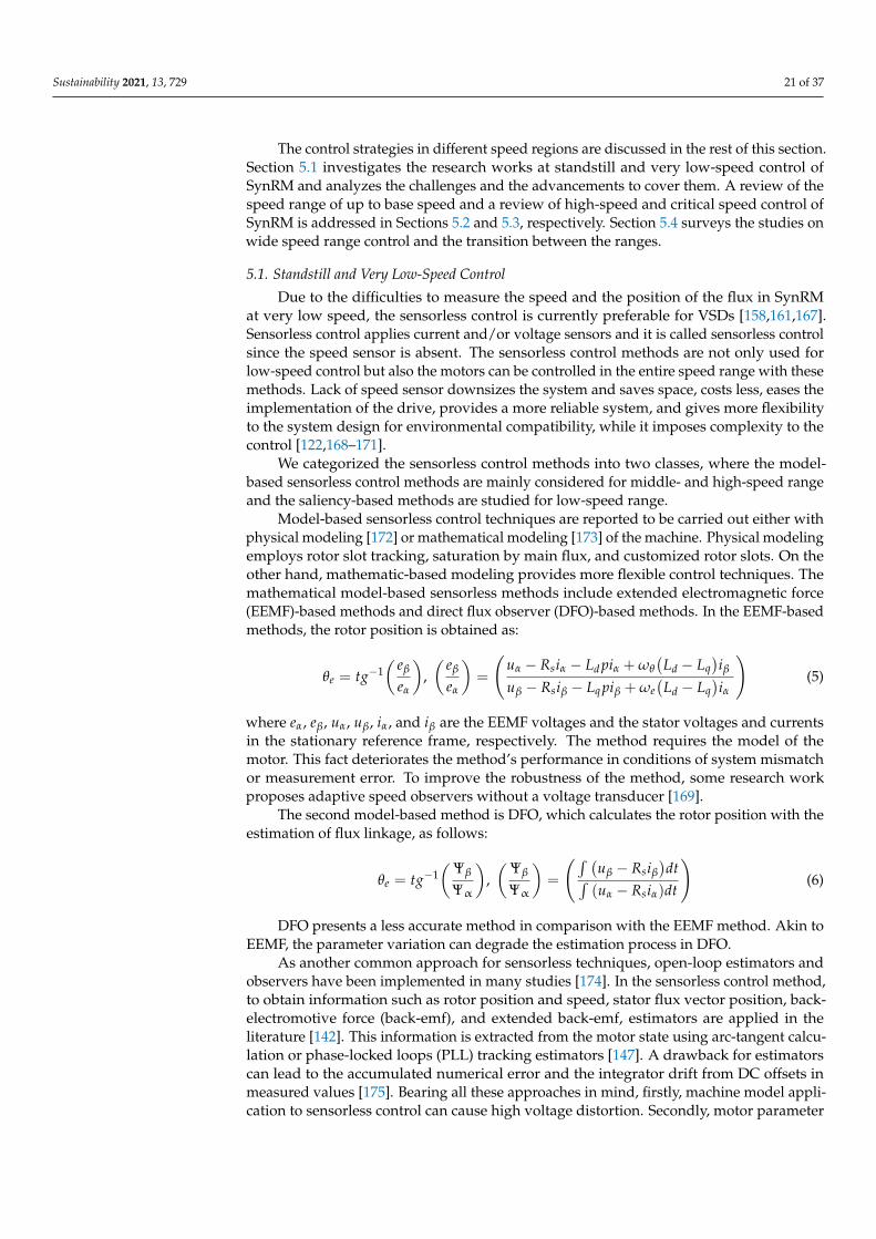
Sustainability 2021, 13, 729 21 of 37
The control strategies in different speed regions are discussed in the rest of this section.Section 5.1 investigates the research works at standstill and very low-speed control ofSynRM and analyzes the challenges and the advancements to cover them. A review of thespeed range of up to base speed and a review of high-speed and critical speed control ofSynRM is addressed in Sections 5.2 and 5.3, respectively. Section 5.4 surveys the studies onwide speed range control and the transition between the ranges.
5.1. Standstill and Very Low-Speed Control
Due to the difficulties to measure the speed and the position of the flux in SynRMat very low speed, the sensorless control is currently preferable for VSDs [158,161,167].Sensorless control applies current and/or voltage sensors and it is called sensorless controlsince the speed sensor is absent. The sensorless control methods are not only used forlow-speed control but also the motors can be controlled in the entire speed range with thesemethods. Lack of speed sensor downsizes the system and saves space, costs less, eases theimplementation of the drive, provides a more reliable system, and gives more flexibilityto the system design for environmental compatibility, while it imposes complexity to thecontrol [122,168–171].
We categorized the sensorless control methods into two classes, where the model-based sensorless control methods are mainly considered for middle- and high-speed rangeand the saliency-based methods are studied for low-speed range.
Model-based sensorless control techniques are reported to be carried out either withphysical modeling [172] or mathematical modeling [173] of the machine. Physical modelingemploys rotor slot tracking, saturation by main flux, and customized rotor slots. On theother hand, mathematic-based modeling provides more flexible control techniques. Themathematical model-based sensorless methods include extended electromagnetic force(EEMF)-based methods and direct flux observer (DFO)-based methods. In the EEMF-basedmethods, the rotor position is obtained as:
θe = tg−1( eβ
eα
),( eβ
eα
)=
(uα − Rsiα − Ld piα + ωθ
(Ld − Lq
)iβ
uβ − Rsiβ − Lq piβ + ωe(
Ld − Lq)iα
)(5)
where eα, eβ, uα, uβ, iα, and iβ are the EEMF voltages and the stator voltages and currentsin the stationary reference frame, respectively. The method requires the model of themotor. This fact deteriorates the method’s performance in conditions of system mismatchor measurement error. To improve the robustness of the method, some research workproposes adaptive speed observers without a voltage transducer [169].
The second model-based method is DFO, which calculates the rotor position with theestimation of flux linkage, as follows:
θe = tg−1(Ψβ
Ψα
),(Ψβ
Ψα
)=
(∫ (uβ − Rsiβ
)dt∫
(uα − Rsiα)dt
)(6)
DFO presents a less accurate method in comparison with the EEMF method. Akin toEEMF, the parameter variation can degrade the estimation process in DFO.
As another common approach for sensorless techniques, open-loop estimators andobservers have been implemented in many studies [174]. In the sensorless control method,to obtain information such as rotor position and speed, stator flux vector position, back-electromotive force (back-emf), and extended back-emf, estimators are applied in theliterature [142]. This information is extracted from the motor state using arc-tangent calcu-lation or phase-locked loops (PLL) tracking estimators [147]. A drawback for estimatorscan lead to the accumulated numerical error and the integrator drift from DC offsets inmeasured values [175]. Bearing all these approaches in mind, firstly, machine model appli-cation to sensorless control can cause high voltage distortion. Secondly, motor parameter
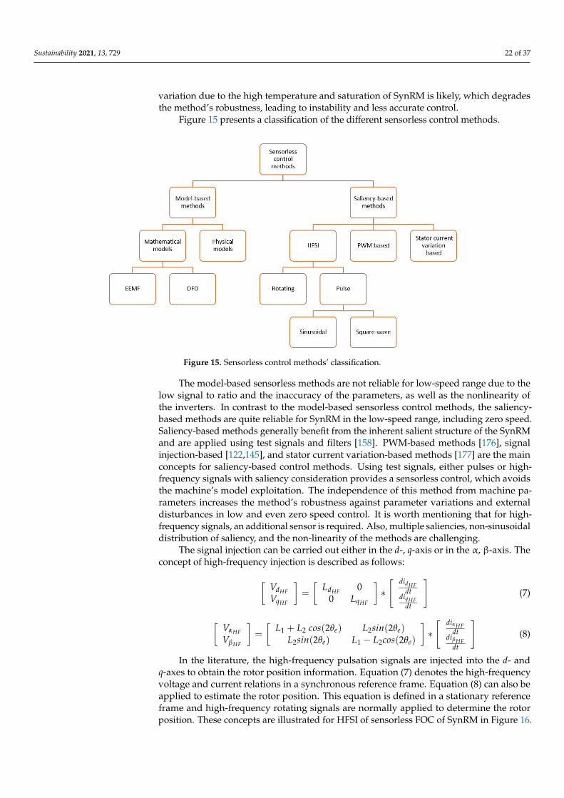
Sustainability 2021, 13, 729 22 of 37
variation due to the high temperature and saturation of SynRM is likely, which degradesthe method’s robustness, leading to instability and less accurate control.
Figure 15 presents a classification of the different sensorless control methods.Sustainability 2021, 13, x FOR PEER REVIEW 23 of 38
Figure 15. Sensorless control methods’ classification.
The model-based sensorless methods are not reliable for low-speed range due to the low signal to ratio and the inaccuracy of the parameters, as well as the nonlinearity of the inverters. In contrast to the model-based sensorless control methods, the saliency-based methods are quite reliable for SynRM in the low-speed range, including zero speed. Sali-ency-based methods generally benefit from the inherent salient structure of the SynRM and are applied using test signals and filters [158]. PWM-based methods [176], signal in-jection-based [122,145], and stator current variation-based methods [177] are the main concepts for saliency-based control methods. Using test signals, either pulses or high-fre-quency signals with saliency consideration provides a sensorless control, which avoids the machine’s model exploitation. The independence of this method from machine pa-rameters increases the method’s robustness against parameter variations and external dis-turbances in low and even zero speed control. It is worth mentioning that for high-fre-quency signals, an additional sensor is required. Also, multiple saliencies, non-sinusoidal distribution of saliency, and the non-linearity of the methods are challenging.
The signal injection can be carried out either in the d, q-axis or in the α, β-axis. The concept of high-frequency injection is described as follows:
𝑉𝑉 = 𝐿 00 𝐿 ∗ 𝑑𝑖𝑑𝑡𝑑𝑖𝑑𝑡 (7)
𝑉𝑉 = 𝐿 + 𝐿 𝑐𝑜𝑠 (2𝜃 ) 𝐿 𝑠𝑖𝑛 (2𝜃 )𝐿 𝑠𝑖𝑛 (2𝜃 ) 𝐿 − 𝐿 𝑐𝑜𝑠 (2𝜃 ) ∗ 𝑑𝑖𝑑𝑡𝑑𝑖𝑑𝑡 (8)
In the literature, the high-frequency pulsation signals are injected into the d- and q-axes to obtain the rotor position information. Equation (7) denotes the high-frequency voltage and current relations in a synchronous reference frame. Equation (8) can also be applied to estimate the rotor position. This equation is defined in a stationary reference frame and high-frequency rotating signals are normally applied to determine the rotor position. These concepts are illustrated for HFSI of sensorless FOC of SynRM in Figure 16.
Figure 15. Sensorless control methods’ classification.
The model-based sensorless methods are not reliable for low-speed range due to thelow signal to ratio and the inaccuracy of the parameters, as well as the nonlinearity ofthe inverters. In contrast to the model-based sensorless control methods, the saliency-based methods are quite reliable for SynRM in the low-speed range, including zero speed.Saliency-based methods generally benefit from the inherent salient structure of the SynRMand are applied using test signals and filters [158]. PWM-based methods [176], signalinjection-based [122,145], and stator current variation-based methods [177] are the mainconcepts for saliency-based control methods. Using test signals, either pulses or high-frequency signals with saliency consideration provides a sensorless control, which avoidsthe machine’s model exploitation. The independence of this method from machine pa-rameters increases the method’s robustness against parameter variations and externaldisturbances in low and even zero speed control. It is worth mentioning that for high-frequency signals, an additional sensor is required. Also, multiple saliencies, non-sinusoidaldistribution of saliency, and the non-linearity of the methods are challenging.
The signal injection can be carried out either in the d-, q-axis or in the α, β-axis. Theconcept of high-frequency injection is described as follows:
[VdHFVqHF
]=
[LdHF 0
0 LqHF
]∗[ didHF
dtdiqHF
dt
](7)
[VαHF
VβHF
]=
[L1 + L2 cos(2θe) L2sin(2θe)
L2sin(2θe) L1 − L2cos(2θe)
]∗[ diαHF
dtdiβHF
dt
](8)
In the literature, the high-frequency pulsation signals are injected into the d- andq-axes to obtain the rotor position information. Equation (7) denotes the high-frequencyvoltage and current relations in a synchronous reference frame. Equation (8) can also beapplied to estimate the rotor position. This equation is defined in a stationary referenceframe and high-frequency rotating signals are normally applied to determine the rotorposition. These concepts are illustrated for HFSI of sensorless FOC of SynRM in Figure 16.
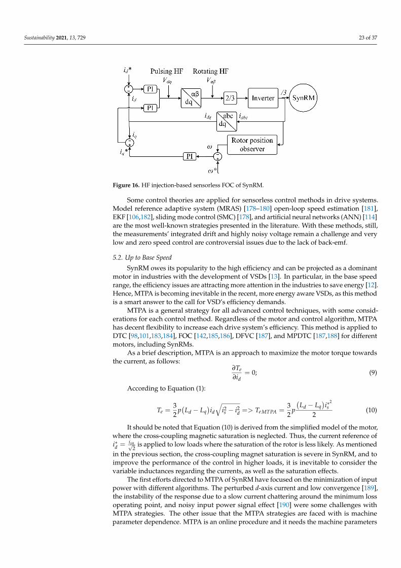
Sustainability 2021, 13, 729 23 of 37Sustainability 2021, 13, x FOR PEER REVIEW 24 of 38
Figure 16. HF injection-based sensorless FOC of SynRM.
Some control theories are applied for sensorless control methods in drive systems. Model reference adaptive system (MRAS) [178–180] open-loop speed estimation [181], EKF [106,182], sliding mode control (SMC) [178], and artificial neural networks (ANN) [114] are the most well-known strategies presented in the literature. With these methods, still, the measurements’ integrated drift and highly noisy voltage remain a challenge and very low and zero speed control are controversial issues due to the lack of back-emf.
5.2. Up to Base Speed SynRM owes its popularity to the high efficiency and can be projected as a dominant
motor in industries with the development of VSDs [13]. In particular, in the base speed range, the efficiency issues are attracting more attention in the industries to save energy [12]. Hence, MTPA is becoming inevitable in the recent, more energy aware VSDs, as this method is a smart answer to the call for VSD’s efficiency demands.
MTPA is a general strategy for all advanced control techniques, with some consider-ations for each control method. Regardless of the motor and control algorithm, MTPA has decent flexibility to increase each drive system’s efficiency. This method is applied to DTC [98,101,183,184], FOC [142,185,186], DFVC [187], and MPDTC [187,188] for different mo-tors, including SynRMs.
As a brief description, MTPA is an approach to maximize the motor torque towards the current, as follows: 𝜕𝑇𝜕𝑖 = 0; (9)
According to Equation (1): 𝑇 = 32 𝑝 𝐿 − 𝐿 𝑖 𝑖 − 𝑖 => 𝑇 = 32 𝑝 𝐿 − 𝐿 𝑖∗2 (10)
It should be noted that Equation (10) is derived from the simplified model of the motor, where the cross-coupling magnetic saturation is neglected. Thus, the current ref-erence of 𝑖∗ = √ is applied to low loads where the saturation of the rotor is less likely. As mentioned in the previous section, the cross-coupling magnet saturation is severe in SynRM, and to improve the performance of the control in higher loads, it is inevitable to consider the variable inductances regarding the currents, as well as the saturation effects.
The first efforts directed to MTPA of SynRM have focused on the minimization of input power with different algorithms. The perturbed d-axis current and low convergence [189], the instability of the response due to a slow current chattering around the minimum loss operating point, and noisy input power signal effect [190] were some challenges with
Figure 16. HF injection-based sensorless FOC of SynRM.
Some control theories are applied for sensorless control methods in drive systems.Model reference adaptive system (MRAS) [178–180] open-loop speed estimation [181],EKF [106,182], sliding mode control (SMC) [178], and artificial neural networks (ANN) [114]are the most well-known strategies presented in the literature. With these methods, still,the measurements’ integrated drift and highly noisy voltage remain a challenge and verylow and zero speed control are controversial issues due to the lack of back-emf.
5.2. Up to Base Speed
SynRM owes its popularity to the high efficiency and can be projected as a dominantmotor in industries with the development of VSDs [13]. In particular, in the base speedrange, the efficiency issues are attracting more attention in the industries to save energy [12].Hence, MTPA is becoming inevitable in the recent, more energy aware VSDs, as this methodis a smart answer to the call for VSD’s efficiency demands.
MTPA is a general strategy for all advanced control techniques, with some consid-erations for each control method. Regardless of the motor and control algorithm, MTPAhas decent flexibility to increase each drive system’s efficiency. This method is applied toDTC [98,101,183,184], FOC [142,185,186], DFVC [187], and MPDTC [187,188] for differentmotors, including SynRMs.
As a brief description, MTPA is an approach to maximize the motor torque towardsthe current, as follows:
∂Te
∂id= 0; (9)
According to Equation (1):
Te =32
p(
Ld − Lq)id
√i2s − i2d => Te MTPA =
32
p
(Ld − Lq
)i∗
2s
2(10)
It should be noted that Equation (10) is derived from the simplified model of the motor,where the cross-coupling magnetic saturation is neglected. Thus, the current reference ofi∗d = isn√
2is applied to low loads where the saturation of the rotor is less likely. As mentioned
in the previous section, the cross-coupling magnet saturation is severe in SynRM, and toimprove the performance of the control in higher loads, it is inevitable to consider thevariable inductances regarding the currents, as well as the saturation effects.
The first efforts directed to MTPA of SynRM have focused on the minimization of inputpower with different algorithms. The perturbed d-axis current and low convergence [189],the instability of the response due to a slow current chattering around the minimum lossoperating point, and noisy input power signal effect [190] were some challenges withMTPA strategies. The other issue that the MTPA strategies are faced with is machineparameter dependence. MTPA is an online procedure and it needs the machine parameters
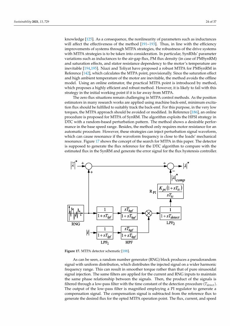
Sustainability 2021, 13, 729 24 of 37
knowledge [125]. As a consequence, the nonlinearity of parameters such as inductanceswill affect the effectiveness of the method [191–193]. Thus, in line with the efficiencyimprovements of systems through MTPA strategies, the robustness of the drive systemswith MTPA strategies is to be taken into consideration. In particular, SynRMs’ parametervariations such as inductances to the air-gap flux, PM flux density (in case of PMSynRM)and saturation effects, and stator resistance dependency to the motor’s temperature areinevitable [194,195]. Niazi and Toliyat have proposed a robust MTPA for PMSynRM inReference [142], which calculates the MTPA point, provisionally. Since the saturation effectand high ambient temperature of the motor are inevitable, the method avoids the offlinemodel. Using an online estimator, the practical MTPA point is introduced by method,which proposes a highly efficient and robust method. However, it is likely to fail with thisstrategy in the initial working point if it is far away from MTPA.
The zero flux situations remain challenging in MTPA control methods. As the positionestimators in many research works are applied using machine back-emf, minimum excita-tion flux should be fulfilled to suitably track the back-emf. For this purpose, in the very lowtorques, the MTPA approach should be avoided or modified. In Reference [186], an onlineprocedure is proposed for MTPA of SynRM. The algorithm exploits the HFSI strategy inDTC with a random-based perturbation pattern. The method shows a desirable perfor-mance in the base speed range. Besides, the method only requires motor resistance for anautomatic procedure. However, these strategies can inject perturbation signal waveform,which can cause resonance if the waveform frequency is close to the loads’ mechanicalresonance. Figure 17 shows the concept of the search for MTPA in this paper. The detectoris supposed to generate the flux reference for the DTC algorithm to compare with theestimated flux in the SynRM and generate the error signal for the flux hysteresis controller.
Sustainability 2021, 13, x FOR PEER REVIEW 25 of 38
MTPA strategies. The other issue that the MTPA strategies are faced with is machine pa-rameter dependence. MTPA is an online procedure and it needs the machine parameters knowledge [125]. As a consequence, the nonlinearity of parameters such as inductances will affect the effectiveness of the method [191–193]. Thus, in line with the efficiency im-provements of systems through MTPA strategies, the robustness of the drive systems with MTPA strategies is to be taken into consideration. In particular, SynRMs’ parameter vari-ations such as inductances to the air-gap flux, PM flux density (in case of PMSynRM) and saturation effects, and stator resistance dependency to the motor’s temperature are inevi-table [194,195]. Niazi and Toliyat have proposed a robust MTPA for PMSynRM in Refer-ence [142], which calculates the MTPA point, provisionally. Since the saturation effect and high ambient temperature of the motor are inevitable, the method avoids the offline model. Using an online estimator, the practical MTPA point is introduced by method, which proposes a highly efficient and robust method. However, it is likely to fail with this strategy in the initial working point if it is far away from MTPA.
The zero flux situations remain challenging in MTPA control methods. As the posi-tion estimators in many research works are applied using machine back-emf, minimum excitation flux should be fulfilled to suitably track the back-emf. For this purpose, in the very low torques, the MTPA approach should be avoided or modified. In Reference [186], an online procedure is proposed for MTPA of SynRM. The algorithm exploits the HFSI strategy in DTC with a random-based perturbation pattern. The method shows a desirable performance in the base speed range. Besides, the method only requires motor resistance for an automatic procedure. However, these strategies can inject perturbation signal waveform, which can cause resonance if the waveform frequency is close to the loads’ mechanical resonance. Figure 17 shows the concept of the search for MTPA in this paper. The detector is supposed to generate the flux reference for the DTC algorithm to compare with the estimated flux in the SynRM and generate the error signal for the flux hysteresis controller.
Figure 17. MTPA detector schematic [188].
As can be seen, a random number generator (RNG) block produces a pseudorandom signal with uniform distribution, which distributes the injected signal on a wider har-monic frequency range. This can result in smoother torque rather than that of pure sinus-oidal signal injection. The same filters are applied for the current and RNG inputs to main-tain the same phase relationship between the signals. Then, the product of the signals is filtered through a low-pass filter with the time constant of the detection procedure
Figure 17. MTPA detector schematic [188].
As can be seen, a random number generator (RNG) block produces a pseudorandomsignal with uniform distribution, which distributes the injected signal on a wider harmonicfrequency range. This can result in smoother torque rather than that of pure sinusoidalsignal injection. The same filters are applied for the current and RNG inputs to maintainthe same phase relationship between the signals. Then, the product of the signals isfiltered through a low-pass filter with the time constant of the detection procedure (Tdetect).The output of the low-pass filter is magnified employing a PI regulator to generate acompensation signal. The compensation signal is subtracted from the reference flux togenerate the desired flux for the opted MTPA operation point. The flux, current, and speed
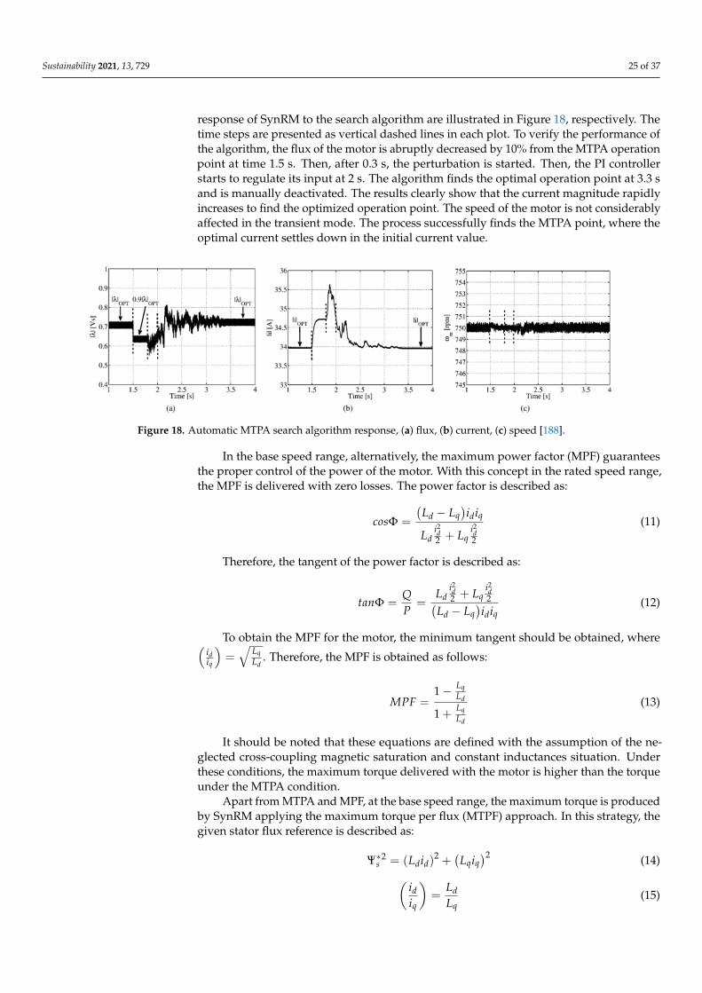
Sustainability 2021, 13, 729 25 of 37
response of SynRM to the search algorithm are illustrated in Figure 18, respectively. Thetime steps are presented as vertical dashed lines in each plot. To verify the performance ofthe algorithm, the flux of the motor is abruptly decreased by 10% from the MTPA operationpoint at time 1.5 s. Then, after 0.3 s, the perturbation is started. Then, the PI controllerstarts to regulate its input at 2 s. The algorithm finds the optimal operation point at 3.3 sand is manually deactivated. The results clearly show that the current magnitude rapidlyincreases to find the optimized operation point. The speed of the motor is not considerablyaffected in the transient mode. The process successfully finds the MTPA point, where theoptimal current settles down in the initial current value.
Sustainability 2021, 13, x FOR PEER REVIEW 26 of 38
(𝑇 ). The output of the low-pass filter is magnified employing a PI regulator to gener-ate a compensation signal. The compensation signal is subtracted from the reference flux to generate the desired flux for the opted MTPA operation point. The flux, current, and speed response of SynRM to the search algorithm are illustrated in Figure 18, respectively. The time steps are presented as vertical dashed lines in each plot. To verify the perfor-mance of the algorithm, the flux of the motor is abruptly decreased by 10% from the MTPA operation point at time 1.5 s. Then, after 0.3 s, the perturbation is started. Then, the PI controller starts to regulate its input at 2 s. The algorithm finds the optimal operation point at 3.3 s and is manually deactivated. The results clearly show that the current magnitude rapidly increases to find the optimized operation point. The speed of the motor is not considerably affected in the transient mode. The process successfully finds the MTPA point, where the optimal current settles down in the initial current value.
Figure 18. Automatic MTPA search algorithm response, (a) flux, (b) current, (c) speed [188].
In the base speed range, alternatively, the maximum power factor (MPF) guarantees the proper control of the power of the motor. With this concept in the rated speed range, the MPF is delivered with zero losses. The power factor is described as: 𝑐𝑜𝑠Φ = 𝐿 − 𝐿 𝑖 𝑖𝐿 𝑖2 + 𝐿 𝑖2 (11)
Therefore, the tangent of the power factor is described as:
𝑡𝑎𝑛Φ = 𝑄𝑃 = 𝐿 𝑖2 + 𝐿 𝑖2𝐿 − 𝐿 𝑖 𝑖 (12)
To obtain the MPF for the motor, the minimum tangent should be obtained, where = . Therefore, the MPF is obtained as follows:
𝑀𝑃𝐹 = 1 − 𝐿𝐿1 + 𝐿𝐿 (13)
It should be noted that these equations are defined with the assumption of the ne-glected cross-coupling magnetic saturation and constant inductances situation. Under these conditions, the maximum torque delivered with the motor is higher than the torque under the MTPA condition.
Apart from MTPA and MPF, at the base speed range, the maximum torque is pro-duced by SynRM applying the maximum torque per flux (MTPF) approach. In this strat-egy, the given stator flux reference is described as: Ψ∗ = (𝐿 𝑖 ) + 𝐿 𝑖 (14)
Figure 18. Automatic MTPA search algorithm response, (a) flux, (b) current, (c) speed [188].
In the base speed range, alternatively, the maximum power factor (MPF) guaranteesthe proper control of the power of the motor. With this concept in the rated speed range,the MPF is delivered with zero losses. The power factor is described as:
cosΦ =
(Ld − Lq
)idiq
Ldi2d2 + Lq
i2d2
(11)
Therefore, the tangent of the power factor is described as:
tanΦ =QP
=Ld
i2d2 + Lq
i2d2(
Ld − Lq)idiq
(12)
To obtain the MPF for the motor, the minimum tangent should be obtained, where(idiq
)=√
LqLd
. Therefore, the MPF is obtained as follows:
MPF =1− Lq
Ld
1 + LqLd
(13)
It should be noted that these equations are defined with the assumption of the ne-glected cross-coupling magnetic saturation and constant inductances situation. Underthese conditions, the maximum torque delivered with the motor is higher than the torqueunder the MTPA condition.
Apart from MTPA and MPF, at the base speed range, the maximum torque is producedby SynRM applying the maximum torque per flux (MTPF) approach. In this strategy, thegiven stator flux reference is described as:
Ψ∗s2 = (Ldid)
2 +(
Lqiq)2 (14)(
idiq
)=
LdLq
(15)
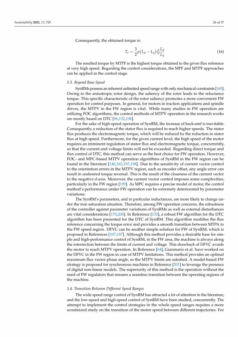
Sustainability 2021, 13, 729 26 of 37
Consequently, the obtained torque is:
Te =32
p(
Ld − Lq)i2d
LdLq
(16)
The resulted torque by MTPF is the highest torque obtained to the given flux referenceat very high speed. Regarding the control considerations, the MPF and MTPF approachescan be applied in the control stage.
5.3. Beyond Base Speed
SynRMs possess an inherent unlimited speed range with only mechanical constraints [165].Owing to the anisotropic rotor design, the saliency of the rotor leads to the reluctancetorque. This specific characteristic of the rotor saliency promotes a more convenient FWoperation for control purposes. In general, for motors in traction applications and spindledrives, the MTPV in the FW region is vital. While many studies in FW operation areutilizing FOC algorithms, the control methods of MTPV operation in the research worksare mostly based on DTC [96,132,196].
For the sake of high-speed operation of SynRM, the increase of back-emf is inevitable.Consequently, a reduction of the stator flux is required to reach higher speeds. The statorflux produces the electromagnetic torque, which will be reduced by the reduction in statorflux at high speed. Furthermore, for the given current level, the high speed of the motorrequires an imminent regulation of stator flux and electromagnetic torque, concurrently,so that the current and voltage limits will not be exceeded. Regarding direct torque andflux control of DTC, this method can serve as the best choice for FW operation. However,FOC- and MPC-based MTPV operation algorithms of SynRM in the FW region can befound in the literature [140,165,197,198]. Due to the sensitivity of current vector controlto the orientation errors in the MTPV region, such as encoder offset, any angle error canresult in undesired torque reversal. This is the result of the closeness of the current vectorto the negative d-axis. Moreover, the current vector control imposes some complexities,particularly in the FW region [199]. As MPC requires a precise model of motor, the controlmethod’s performance under FW operation can be extremely deteriorated by parametervariations.
The SynRM’s parameters, and in particular inductances, are more likely to change un-der the iron saturation situation. Therefore, among FW operation concerns, the robustnessof the controller against parameter variations of SynRMs as well as external disturbancesare vital considerations [170,200]. In Reference [132], a robust FW algorithm for the DTCalgorithm has been presented for the DTC of SynRM. This algorithm modifies the fluxreference concerning the torque error and provides a smooth transition between MTPA tothe FW speed region. DFVC can be another simple solution for FW of SynRM, which isproposed in References [107,187]. Although this method provides a desirable base for sim-ple and high-performance control of SynRM, in the FW area, the machine is always alongthe intersection between the limits of current and voltage. This drawback of DFVC avoidsthe motor to reach MTPV operation. In Reference [64], Gianmario et al. have worked onthe DFVC in the FW region in case of MTPV limitations. This method provides an optimalmaximum flux vector phase angle, so the MTPV limits are satisfied. A model-based FWstrategy is proposed for synchronous machines in Reference [201] to leverage the presenceof digital non-linear models. The superiority of this method is the operation without theneed of FW regulators that ensures a seamless transition between the operating regions ofthe machine.
5.4. Transition Between Different Speed Ranges
The wide speed range control of SynRM has attracted a lot of attention in the literature,and the low-speed and high-speed control of SynRM have been studied, concurrently. Theattempt to implement the control strategies in the whole speed ranges requires a morescrutinized study on the transition of the motor speed between different trajectories. For
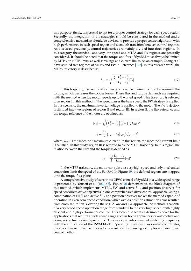
Sustainability 2021, 13, 729 27 of 37
this purpose, firstly, it is crucial to opt for a proper control strategy for each speed region.Secondly, the integration of the strategies should be considered in the method and acomprehensive mechanism should be devised to provide a proper control algorithm withhigh performance in each speed region and a smooth transition between control regimes.As discussed previously, control trajectories are mainly divided into three regions. Inthis category, the standstill and very low-speed and MTPA and FW regimes are generallyconsidered. It should be noted that the torque and flux of SynRM must always be limitedby MTPA or MPTF limits, as well as voltage and current limits. As an example, Zhang et al.have studied two regimes of MTPA and FW in Reference [132]. In this research work, theMTPA trajectory is described as:
|λs| =
√2
3pL2
d + L2q
Ld − Lq|Te| (17)
In this trajectory, the control algorithm produces the minimum current concerning thetorque, which decreases the copper losses. These flux and torque demands are requiredwith the method when the motor speeds up to the rated speed. This trajectory is referredto as region I in this method. If the speed passes the base speed, the FW strategy is applied.In this scenario, the maximum inverter voltage is applied to the motor. The FW trajectoryis divided into two regions of region II and region III. In region II, the flux reference andthe torque reference of the motor are obtained as:
|λs| =√(
L2d − L2
q
)i2d +
(Lq Imax
)2 (18)
Te =3p2(
Ld − Lq)id√
I2max − i2d (19)
where, Imax is the machine’s maximum current. In this region, the machine’s current limitis satisfied. In this study, region III is referred to as the MTPF trajectory. In this region, therelation between the flux and the torque is defined as:
Te =3p4
Ld − Lq
LdLq|λs|2 (20)
In the MTPF trajectory, the motor can spin at a very high speed and only mechanicalconstraints limit the speed of the SynRM. In Figure 19, the defined regions are mappedonto the torque-flux plane.
A comprehensive study of sensorless DFVC control of SynRM in a wide speed rangeis presented by Yousefi et al. [107,187]. Figure 20 demonstrates the block diagram ofthis method, which implements MTPA, FW, and active flux and position observer forspeed sensorless drive objectives in one comprehensive drive control approach. Using acombination of HFSI and active flux and position observer makes the method capable ofoperation in even zero-speed condition, which avoids position estimation error resultedfrom cross-saturation. Covering the MTPA law and FW approach, the method is capableof a very broad speed operation range from standstill to the very high speed, with highlyefficient and high-performance control. This technique seems a desirable choice for theapplications that require a wide speed range such as home appliances, or automotive andaerospace actuators and generators. This work provides constant switching frequencywith the application of the PWM block. Operating in stator-flux-oriented coordinates,the algorithm requires the flux vector precise position causing a complex and less robustcontrol method.
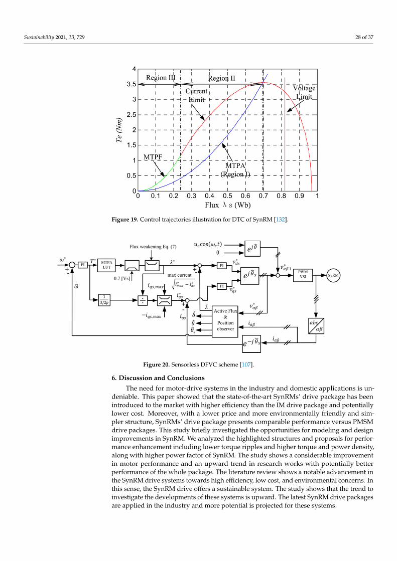
Sustainability 2021, 13, 729 28 of 37Sustainability 2021, 13, x FOR PEER REVIEW 29 of 38
Figure 19. Control trajectories illustration for DTC of SynRM [132].
A comprehensive study of sensorless DFVC control of SynRM in a wide speed range is presented by Yousefi et al. [107,187]. Figure 20 demonstrates the block diagram of this method, which implements MTPA, FW, and active flux and position observer for speed sensorless drive objectives in one comprehensive drive control approach. Using a combi-nation of HFSI and active flux and position observer makes the method capable of opera-tion in even zero-speed condition, which avoids position estimation error resulted from cross-saturation. Covering the MTPA law and FW approach, the method is capable of a very broad speed operation range from standstill to the very high speed, with highly effi-cient and high-performance control. This technique seems a desirable choice for the ap-plications that require a wide speed range such as home appliances, or automotive and aerospace actuators and generators. This work provides constant switching frequency with the application of the PWM block. Operating in stator-flux-oriented coordinates, the algorithm requires the flux vector precise position causing a complex and less robust con-trol method.
Figure 20. Sensorless DFVC scheme [107].
6. Discussion and Conclusions The need for motor-drive systems in the industry and domestic applications is unde-
niable. This paper showed that the state-of-the-art SynRMs’ drive package has been intro-duced to the market with higher efficiency than the IM drive package and potentially
Figure 19. Control trajectories illustration for DTC of SynRM [132].
Sustainability 2021, 13, x FOR PEER REVIEW 29 of 38
Figure 19. Control trajectories illustration for DTC of SynRM [132].
A comprehensive study of sensorless DFVC control of SynRM in a wide speed range is presented by Yousefi et al. [107,187]. Figure 20 demonstrates the block diagram of this method, which implements MTPA, FW, and active flux and position observer for speed sensorless drive objectives in one comprehensive drive control approach. Using a combi-nation of HFSI and active flux and position observer makes the method capable of opera-tion in even zero-speed condition, which avoids position estimation error resulted from cross-saturation. Covering the MTPA law and FW approach, the method is capable of a very broad speed operation range from standstill to the very high speed, with highly effi-cient and high-performance control. This technique seems a desirable choice for the ap-plications that require a wide speed range such as home appliances, or automotive and aerospace actuators and generators. This work provides constant switching frequency with the application of the PWM block. Operating in stator-flux-oriented coordinates, the algorithm requires the flux vector precise position causing a complex and less robust con-trol method.
Figure 20. Sensorless DFVC scheme [107].
6. Discussion and Conclusions The need for motor-drive systems in the industry and domestic applications is unde-
niable. This paper showed that the state-of-the-art SynRMs’ drive package has been intro-duced to the market with higher efficiency than the IM drive package and potentially
Figure 20. Sensorless DFVC scheme [107].
6. Discussion and Conclusions
The need for motor-drive systems in the industry and domestic applications is un-deniable. This paper showed that the state-of-the-art SynRMs’ drive package has beenintroduced to the market with higher efficiency than the IM drive package and potentiallylower cost. Moreover, with a lower price and more environmentally friendly and sim-pler structure, SynRMs’ drive package presents comparable performance versus PMSMdrive packages. This study briefly investigated the opportunities for modeling and designimprovements in SynRM. We analyzed the highlighted structures and proposals for perfor-mance enhancement including lower torque ripples and higher torque and power density,along with higher power factor of SynRM. The study shows a considerable improvementin motor performance and an upward trend in research works with potentially betterperformance of the whole package. The literature review shows a notable advancement inthe SynRM drive systems towards high efficiency, low cost, and environmental concerns. Inthis sense, the SynRM drive offers a sustainable system. The study shows that the trend toinvestigate the developments of these systems is upward. The latest SynRM drive packagesare applied in the industry and more potential is projected for these systems.
Sustainability 2021, 13, 729 29 of 37
Motor control methods may not guarantee the acceptable level of all control aspects,for example, good robustness, fast dynamic, low torque ripple, and accurate tracking, whensingly used in drive systems. For this reason, research and development in the field ofelectric drives are incrementally updated to develop the technical knowledge and providea modified version of the drive system, as much as possible. We studied the more popularcontrol strategies and investigated the advantages and disadvantages of each method.Regarding the highlighted feature of each method, we classified the methods, which canprovide a reliable reference for the researchers to overview the motor control methods.
A high-performance controller for VSD-fed SynRMs was evaluated by different factors.Three more important factors are the robustness of the controller against parameter varia-tion and external disturbances, the level of torque ripples imposed on the average torque,and the more efficient drive in a wide speed range. Both electrical parameter variabilityand torque ripple are chiefly generated from the anisotropic rotor structure of SynRMs.The undesirable parameter variation can lead to degraded performance of the drive system.Furthermore, disregarding the system mismatch is in contradiction to efficiency, productiv-ity, and environmental and energy issues. To tackle parameter variation problems, a robustcontrol algorithm should be developed because the parameter variation has a direct impacton machine controllability. The robustness of the controller against external disturbances,such as tough load torques, can be investigated and modified. The study shows that oneof the biggest concerns in the SynRMs drive systems is the high torque ripples comparedto other technologies. A high level of torque ripple causes pulsation and vibration, whichcan not only lead to the low efficiency of the systems but also the noise in the environment.We reviewed the techniques and proposals for both the design and control aspects that areaddressed to decrease the torque ripples.
Designing a control method to cover the whole speed range of the motors withdesired efficiency and performance seems an overwhelming task due to the imposedtheoretical and practical constraints. Considering the vast potential uses of SynRMs withVSDs, more intelligent control techniques are projected to be developed to preserve thestriking efficiency of these motors in a wide speed range with desirable performance inboth transient moods and steady-state. This expanded review paper covered the controlmethods that are proposed to enhance the performance and controllability and efficiencyof the SynRM from standstill to very high speeds. We gathered some approaches for othermotor technologies that can be applied to SynRM with some modifications and advisedfor future research works. The findings and outcomes of the paper may be interesting andusable for researchers, industrial companies, and manufacturers of SynRM drive systems.
Author Contributions: Conceptualization, methodology, validation, formal analysis, writing—original draft preparation, H.H.; writing—review and editing, resources, funding acquisition, A.R.;project administration, T.V.; investigation, A.K., E.A. and D.V.L.; supervision, A.B. The literaturereview was carried out by H.H. towards Ph.D. study under the supervision of A.R. and A.B. Thestudy was managed by A.K. and T.V. and D.V.L. and E.A. collaborated in the survey for revision andcollecting the database. All authors have read and agreed to the published version of the manuscript.
Funding: The research has been supported by the Estonian Research Council under grant PSG453“Digital twin for propulsion drive of an autonomous electric vehicle”.
Institutional Review Board Statement: Not applicable.
Informed Consent Statement: Not applicable.
Data Availability Statement: Data is contained within the article or supplementary material.
Conflicts of Interest: The authors declare no conflict of interest.
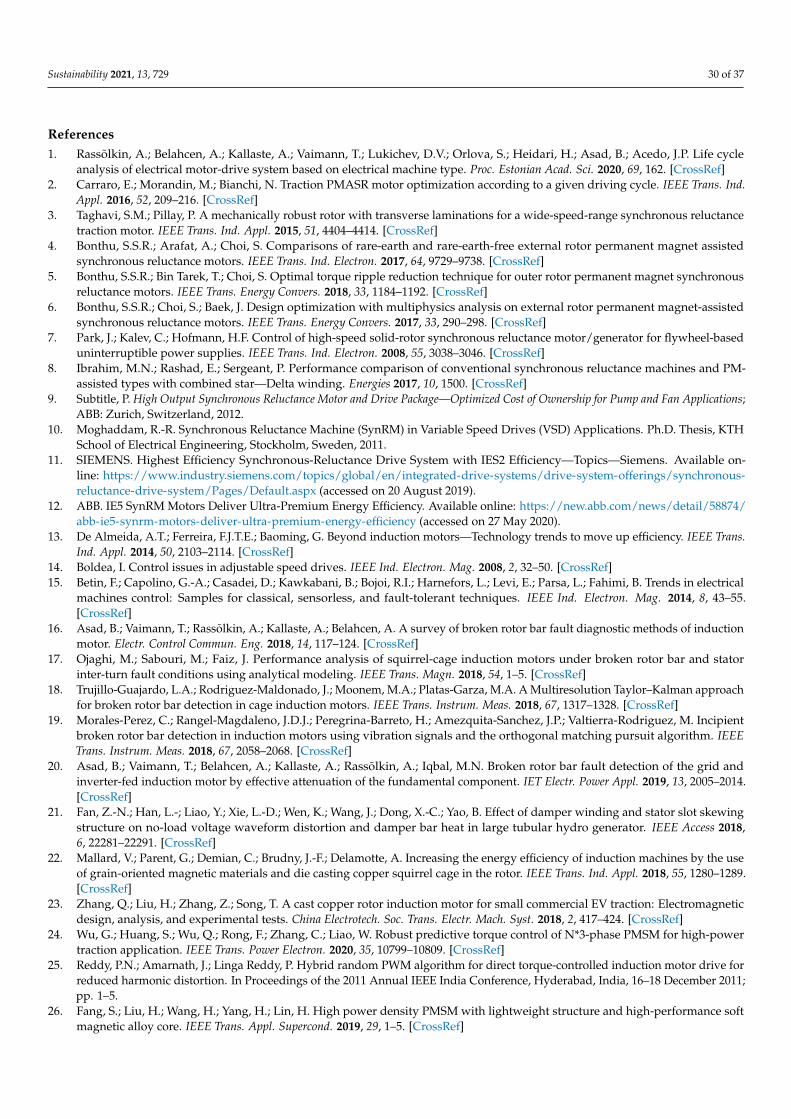
Sustainability 2021, 13, 729 30 of 37
References1. Rassõlkin, A.; Belahcen, A.; Kallaste, A.; Vaimann, T.; Lukichev, D.V.; Orlova, S.; Heidari, H.; Asad, B.; Acedo, J.P. Life cycle
analysis of electrical motor-drive system based on electrical machine type. Proc. Estonian Acad. Sci. 2020, 69, 162. [CrossRef]2. Carraro, E.; Morandin, M.; Bianchi, N. Traction PMASR motor optimization according to a given driving cycle. IEEE Trans. Ind.
Appl. 2016, 52, 209–216. [CrossRef]3. Taghavi, S.M.; Pillay, P. A mechanically robust rotor with transverse laminations for a wide-speed-range synchronous reluctance
traction motor. IEEE Trans. Ind. Appl. 2015, 51, 4404–4414. [CrossRef]4. Bonthu, S.S.R.; Arafat, A.; Choi, S. Comparisons of rare-earth and rare-earth-free external rotor permanent magnet assisted
synchronous reluctance motors. IEEE Trans. Ind. Electron. 2017, 64, 9729–9738. [CrossRef]5. Bonthu, S.S.R.; Bin Tarek, T.; Choi, S. Optimal torque ripple reduction technique for outer rotor permanent magnet synchronous
reluctance motors. IEEE Trans. Energy Convers. 2018, 33, 1184–1192. [CrossRef]6. Bonthu, S.S.R.; Choi, S.; Baek, J. Design optimization with multiphysics analysis on external rotor permanent magnet-assisted
synchronous reluctance motors. IEEE Trans. Energy Convers. 2017, 33, 290–298. [CrossRef]7. Park, J.; Kalev, C.; Hofmann, H.F. Control of high-speed solid-rotor synchronous reluctance motor/generator for flywheel-based
uninterruptible power supplies. IEEE Trans. Ind. Electron. 2008, 55, 3038–3046. [CrossRef]8. Ibrahim, M.N.; Rashad, E.; Sergeant, P. Performance comparison of conventional synchronous reluctance machines and PM-
assisted types with combined star—Delta winding. Energies 2017, 10, 1500. [CrossRef]9. Subtitle, P. High Output Synchronous Reluctance Motor and Drive Package—Optimized Cost of Ownership for Pump and Fan Applications;
ABB: Zurich, Switzerland, 2012.10. Moghaddam, R.-R. Synchronous Reluctance Machine (SynRM) in Variable Speed Drives (VSD) Applications. Ph.D. Thesis, KTH
School of Electrical Engineering, Stockholm, Sweden, 2011.11. SIEMENS. Highest Efficiency Synchronous-Reluctance Drive System with IES2 Efficiency—Topics—Siemens. Available on-
line: https://www.industry.siemens.com/topics/global/en/integrated-drive-systems/drive-system-offerings/synchronous-reluctance-drive-system/Pages/Default.aspx (accessed on 20 August 2019).
12. ABB. IE5 SynRM Motors Deliver Ultra-Premium Energy Efficiency. Available online: https://new.abb.com/news/detail/58874/abb-ie5-synrm-motors-deliver-ultra-premium-energy-efficiency (accessed on 27 May 2020).
13. De Almeida, A.T.; Ferreira, F.J.T.E.; Baoming, G. Beyond induction motors—Technology trends to move up efficiency. IEEE Trans.Ind. Appl. 2014, 50, 2103–2114. [CrossRef]
14. Boldea, I. Control issues in adjustable speed drives. IEEE Ind. Electron. Mag. 2008, 2, 32–50. [CrossRef]15. Betin, F.; Capolino, G.-A.; Casadei, D.; Kawkabani, B.; Bojoi, R.I.; Harnefors, L.; Levi, E.; Parsa, L.; Fahimi, B. Trends in electrical
machines control: Samples for classical, sensorless, and fault-tolerant techniques. IEEE Ind. Electron. Mag. 2014, 8, 43–55.[CrossRef]
16. Asad, B.; Vaimann, T.; Rassõlkin, A.; Kallaste, A.; Belahcen, A. A survey of broken rotor bar fault diagnostic methods of inductionmotor. Electr. Control Commun. Eng. 2018, 14, 117–124. [CrossRef]
17. Ojaghi, M.; Sabouri, M.; Faiz, J. Performance analysis of squirrel-cage induction motors under broken rotor bar and statorinter-turn fault conditions using analytical modeling. IEEE Trans. Magn. 2018, 54, 1–5. [CrossRef]
18. Trujillo-Guajardo, L.A.; Rodriguez-Maldonado, J.; Moonem, M.A.; Platas-Garza, M.A. A Multiresolution Taylor–Kalman approachfor broken rotor bar detection in cage induction motors. IEEE Trans. Instrum. Meas. 2018, 67, 1317–1328. [CrossRef]
19. Morales-Perez, C.; Rangel-Magdaleno, J.D.J.; Peregrina-Barreto, H.; Amezquita-Sanchez, J.P.; Valtierra-Rodriguez, M. Incipientbroken rotor bar detection in induction motors using vibration signals and the orthogonal matching pursuit algorithm. IEEETrans. Instrum. Meas. 2018, 67, 2058–2068. [CrossRef]
20. Asad, B.; Vaimann, T.; Belahcen, A.; Kallaste, A.; Rassõlkin, A.; Iqbal, M.N. Broken rotor bar fault detection of the grid andinverter-fed induction motor by effective attenuation of the fundamental component. IET Electr. Power Appl. 2019, 13, 2005–2014.[CrossRef]
21. Fan, Z.-N.; Han, L.-; Liao, Y.; Xie, L.-D.; Wen, K.; Wang, J.; Dong, X.-C.; Yao, B. Effect of damper winding and stator slot skewingstructure on no-load voltage waveform distortion and damper bar heat in large tubular hydro generator. IEEE Access 2018,6, 22281–22291. [CrossRef]
22. Mallard, V.; Parent, G.; Demian, C.; Brudny, J.-F.; Delamotte, A. Increasing the energy efficiency of induction machines by the useof grain-oriented magnetic materials and die casting copper squirrel cage in the rotor. IEEE Trans. Ind. Appl. 2018, 55, 1280–1289.[CrossRef]
23. Zhang, Q.; Liu, H.; Zhang, Z.; Song, T. A cast copper rotor induction motor for small commercial EV traction: Electromagneticdesign, analysis, and experimental tests. China Electrotech. Soc. Trans. Electr. Mach. Syst. 2018, 2, 417–424. [CrossRef]
24. Wu, G.; Huang, S.; Wu, Q.; Rong, F.; Zhang, C.; Liao, W. Robust predictive torque control of N*3-phase PMSM for high-powertraction application. IEEE Trans. Power Electron. 2020, 35, 10799–10809. [CrossRef]
25. Reddy, P.N.; Amarnath, J.; Linga Reddy, P. Hybrid random PWM algorithm for direct torque-controlled induction motor drive forreduced harmonic distortion. In Proceedings of the 2011 Annual IEEE India Conference, Hyderabad, India, 16–18 December 2011;pp. 1–5.
26. Fang, S.; Liu, H.; Wang, H.; Yang, H.; Lin, H. High power density PMSM with lightweight structure and high-performance softmagnetic alloy core. IEEE Trans. Appl. Supercond. 2019, 29, 1–5. [CrossRef]
Sustainability 2021, 13, 729 31 of 37
27. Xu, J.; Zhang, B.; Kuang, X.; Guo, H.; Guo, S. Influence analysis of slot parameters and high torque density optimisation for dualredundant permanent magnet motor in aerospace application. IET Electr. Power Appl. 2020, 14, 1263–1273. [CrossRef]
28. Kong, Y.; Lin, M.; Jia, L. A novel high-power density permanent-magnet synchronous machine with wide speed range. IEEETrans. Magn. 2020, 56, 1–6. [CrossRef]
29. Chau, K.T. Electric Vehicle Machines and Drives: Design, Analysis and Application; John Wiley and Sons: Chichester, UK, 2015.30. Korn, N.; Vaimann, T.; Kallaste, A.; Belahcen, A. Comparative study of slow speed slotless synchronous generator using SmCo
and NdFeB permanent magnets. In Proceedings of the 2014 Electric Power Quality and Supply Reliability Conference (PQ),Rakvere, Estonia, 11–13 June 2014; pp. 247–250.
31. Pellegrino, G.; Jahns, T.M.; Bianchi, N.; Soong, W.; Cupertino, F. The Rediscovery of Synchronous Reluctance and Ferrite PermanentMagnet Motors; Springer: Cham, Switzerland, 2016.
32. Boldea, I.; Tutelea, L.N.; Parsa, L.; Dorrell, D. Automotive electric propulsion systems with reduced or no permanent magnets:An overview. IEEE Trans. Ind. Electron. 2014, 61, 5696–5711. [CrossRef]
33. Moghaddam, R.-R.; Gyllensten, F. Novel high-performance SynRM design method: An easy approach for a complicated rotortopology. IEEE Trans. Ind. Electron. 2014, 61, 5058–5065. [CrossRef]
34. Bianchi, N.; Fornasiero, E.; Soong, W. Selection of PM flux linkage for maximum low-speed torque rating in a PM-assistedsynchronous reluctance machine. IEEE Trans. Ind. Appl. 2015, 51, 3600–3608. [CrossRef]
35. Di Nardo, M.; Calzo, G.L.; Galea, M.; Gerada, C. Design optimization of a high-speed synchronous reluctance machine. IEEETrans. Ind. Appl. 2018, 54, 233–243. [CrossRef]
36. Taghavi, S.; Pillay, P. A sizing methodology of the synchronous reluctance motor for traction applications. IEEE J. Emerg. Sel. Top.Power Electron. 2014, 2, 329–340. [CrossRef]
37. Moghaddam, R.R.; Magnussen, F.; Sadarangani, C. Theoretical and experimental reevaluation of synchronous reluctance machine.IEEE Trans. Ind. Electron. 2010, 57, 6–13. [CrossRef]
38. Huynh, T.A.; Hsieh, M.-F. Comparative study of PM-Assisted SynRM and IPMSM on constant power speed range for EVapplications. IEEE Trans. Magn. 2017, 53, 1–6. [CrossRef]
39. Kumar, G.V.; Chuang, C.-H.; Lu, M.-Z.; Liaw, C.-M. Development of an electric vehicle synchronous reluctance motor drive. IEEETrans. Veh. Technol. 2020, 69, 5012–5024. [CrossRef]
40. Herrera, D.; Villegas, J.; Galván, E.; Carrasco, J.M. Powertrain EV synchronous reluctance motor design with redundant topologywith novel control. IET Electr. Power Appl. 2019, 13, 1647–1659. [CrossRef]
41. ABB. All-Compatible ACS880 Single Drives—Industrial Drives—Unlimited Possibilities for Your Business (Low Voltage AC).Available online: https://new.abb.com/drives/low-voltage-ac/industrial-drives/acs880-single-drives (accessed on 24 August2020).
42. Foo, G.; Rahman, M.F. Sensorless direct torque and flux controlled IPM synchronous motor drive at very low speed withoutsignal injection. IEEE Trans. Ind. Electron. 2009, 57, 395–403. [CrossRef]
43. Fei, W.-Z.; Luk, P.C.-K. Torque ripple reduction of a direct-drive permanent-magnet synchronous machine by material-efficientaxial pole pairing. IEEE Trans. Ind. Electron. 2011, 59, 2601–2611. [CrossRef]
44. Bedetti, N.; Calligaro, S.; Petrella, R. Stand-still self-identification of flux characteristics for synchronous reluctance machinesusing novel saturation approximating function and multiple linear regression. IEEE Trans. Ind. Appl. 2016, 52, 3083–3092.[CrossRef]
45. ABB. Synchronous Reluctance Motor-Drive Package for Machine Builders. High Performance for Ultimate Machine Design.Available online: http://search-ext.abb.com/library/Download.aspx?DocumentID=3AUA0000120962&LanguageCode=en&DocumentPartId=1&Action=Launch (accessed on 24 August 2020).
46. Ibrahim, M.N.; Abdel-Khalik, A.S.; Rashad, E.E.M.; Sergeant, P. An improved torque density synchronous reluctance machinewith a combined star–delta winding layout. IEEE Trans. Energy Convers. 2018, 33, 1015–1024. [CrossRef]
47. Betz, R.; Lagerquist, R.; Jovanovic, M.; Miller, T.; Middleton, R. Control of synchronous reluctance machines. IEEE Trans. Ind.Appl. 1993, 29, 1110–1122. [CrossRef]
48. ABB. Synchronous Reluctance Motor-Drive Package for Industrial Use—Optimized Cost of Ownership. Available online:https://www.baldor.com/mvc/DownloadCenter/Files/3AUA0000132610 (accessed on 24 August 2020).
49. IEC Webstore. IEC 60034-30-1:2014—Pump, Motor, Water Management, Smart City, Energy Efficiency. Available online:https://webstore.iec.ch/publication/136 (accessed on 15 February 2019).
50. IEC Webstore. IEC TS 60034-30-2:2016—Energy Efficiency, Efficiency Rating. Available online: https://webstore.iec.ch/publication/30830 (accessed on 15 February 2019).
51. Wang, Y.; Ionel, D.M.; Dorrell, D.G.; Stretz, S. Establishing the power factor limitations for synchronous reluctance machines.IEEE Trans. Magn. 2015, 51, 1–4. [CrossRef]
52. Heidari, H.; Andriushchenko, E.; Rassõlkin, A.; Demidova, G.L. Comparison of synchronous reluctance machine and permanentmagnet-assisted synchronous reluctance machine performance characteristics. In Proceedings of the 2020 27th InternationalWorkshop on Electric Drives: MPEI Department of Electric Drives 90th Anniversary (IWED), Moscow, Russia, 27–30 January2020; pp. 9–13.
53. Vagati, A.; Canova, A.; Chiampi, M.; Pastorelli, M.; Repetto, M. Design refinement of synchronous reluctance motors throughfinite-element analysis. IEEE Trans. Ind. Appl. 2000, 36, 1094–1102. [CrossRef]
Sustainability 2021, 13, 729 32 of 37
54. Park, J.-M.; Park, S.-J.; Lee, M.-M.; Chun, J.-S.; Lee, J.-H. Rotor design on torque ripple reduction for a synchronous reluctancemotor with concentrated winding using response surface methodology. IEEE Trans. Magn. 2006, 42, 3479–3481. [CrossRef]
55. Diao, X.; Zhu, H.; Qin, Y.; Hua, Y. Torque ripple minimization for bearingless synchronous reluctance motor. IEEE Trans. Appl.Supercond. 2018, 28, 1–5. [CrossRef]
56. Ibrahim, M.N.; Sergeant, P.; Rashad, E. Simple design approach for low torque ripple and high output torque synchronousreluctance motors. Energies 2016, 9, 942. [CrossRef]
57. Uddin, M.N.; Rahman, M.M. Online torque-flux estimation-based nonlinear torque and flux control scheme of IPMSM drive forreduced torque ripples. IEEE Trans. Power Electron. 2018, 34, 636–645. [CrossRef]
58. Lipo, T.A. Synchronous reluctance machines—A viable alternative for AC drives? Electr. Mach. Power Syst. 1991, 19, 659–671.[CrossRef]
59. Taghavi, S.; Pillay, P. A novel grain-oriented lamination rotor core assembly for a synchronous reluctance traction motor with areduced torque ripple algorithm. IEEE Trans. Ind. Appl. 2016, 52, 3729–3738. [CrossRef]
60. Bianchi, N.; Bolognani, S.; Bon, D.; Pr, M.D. Torque harmonic compensation in a synchronous reluctance motor. IEEE Trans.Energy Convers. 2008, 23, 466–473. [CrossRef]
61. Bianchi, N.; Bolognani, S.; Bon, D.; Pre, M.D. Rotor flux-barrier design for torque ripple reduction in synchronous reluctance andPM-assisted synchronous reluctance motors. IEEE Trans. Ind. Appl. 2009, 45, 921–928. [CrossRef]
62. Bianchi, N.; Bolognani, S.; Carraro, E.; Castiello, M.; Fornasiero, E. Electric vehicle traction based on synchronous reluctancemotors. IEEE Trans. Ind. Appl. 2016, 52, 4762–4769. [CrossRef]
63. Rassõlkin, A.; Heidari, H.; Kallaste, A.; Acedo, J.P.; Romero-Cadaval, E. Efficiency map comparison of induction and synchronousreluctance motors. In Proceedings of the 2019 26th International Workshop on Electric Drives: Improvement in Efficiency ofElectric Drives (IWED), Moscow, Russia, 30 January–2 February 2019; pp. 4–7.
64. Pellegrino, G.-M.L.; Armando, E.; Guglielmi, P. Direct-flux vector control of IPM motor drives in the maximum torque per voltagespeed range. IEEE Trans. Ind. Electron. 2012, 59, 3780–3788. [CrossRef]
65. Barcaro, M.; Bianchi, N.; Magnussen, F. Permanent-magnet optimization in permanent-magnet-assisted synchronous reluctancemotor for a wide constant-power speed range. IEEE Trans. Ind. Electron. 2012, 59, 2495–2502. [CrossRef]
66. Liu, H.-C.; Kim, I.-G.; Oh, Y.J.; Lee, J.; Go, S.-C. Design of permanent magnet-assisted synchronous reluctance motor formaximized Back-EMF and torque ripple reduction. IEEE Trans. Magn. 2017, 53, 1–4. [CrossRef]
67. Flieller, D.; Nguyen, N.K.; Wira, P.; Sturtzer, G.; Abdeslam, D.O.; Mercklé, J. A self-learning solution for torque ripple reduction fornonsinusoidal permanent-magnet motor drives based on artificial neural networks. IEEE Trans. Ind. Electron. 2014, 61, 655–666.[CrossRef]
68. Zhu, H.; Xiao, X.; Li, Y. Torque ripple reduction of the torque predictive control scheme for permanent-magnet synchronousmotors. IEEE Trans. Ind. Electron. 2011, 59, 871–877. [CrossRef]
69. Wang, B.; Wang, J.; Griffo, A.; Sun, Z.; Chong, E. A fault tolerant machine drive based on permanent magnet assisted synchronousreluctance machine. In Proceedings of the 2016 IEEE Energy Conversion Congress and Exposition (ECCE), Milwaukee, WI, USA,18–22 September 2016; pp. 1–8.
70. Arafat, A.; Choi, S.; Baek, J. Open-phase fault detection of a five-phase permanent magnet assisted synchronous reluctance motorbased on symmetrical components theory. IEEE Trans. Ind. Electron. 2017, 64, 6465–6474. [CrossRef]
71. Ilamparithi, T.C.; Nandi, S. Detection of eccentricity faults in three-phase reluctance synchronous motor. IEEE Trans. Ind. Appl.2012, 48, 1307–1317. [CrossRef]
72. Wang, B.; Wang, J.; Griffo, A.; Sen, B. Experimental assessments of a triple redundant nine-phase fault-tolerant PMA SynRMdrive. IEEE Trans. Ind. Electron. 2019, 66, 772–783. [CrossRef]
73. Heidari, H.; Rassõlkin, A.; Holakooie, M.H.; Vaimann, T.; Kallaste, A.; Belahcen, A.; Lukichev, D.V. A Parallel estimation systemof stator resistance and rotor speed for active disturbance rejection control of six-phase induction motor. Energies 2020, 13, 1121.[CrossRef]
74. Asad, B.; Vaimann, T.; Belahcen, A.; Kallaste, A.; Rassolkin, A.; Heidari, H. The Low Voltage Start-up Test of Induction Motor forthe Detection of Broken Bars. In Proceedings of the 2020 International Conference on Electrical Machines (ICEM), Gothenburg,Sweden, 23–26 August 2020; Volume 1.
75. Asad, B.; Vaimann, T.; Rassõlkin, A.; Kallaste, A.; Belahcen, A. Review of electrical machine diagnostic methods applicability inthe perspective of industry 4.0. Electr. Control Commun. Eng. 2018, 14, 1–9. [CrossRef]
76. Boglietti, A.; Cavagnino, A.; Pastorelli, M.; Staton, D.; Vagati, A. Thermal analysis of induction and synchronous reluctancemotors. IEEE Trans. Ind. Appl. 2006, 42, 675–680. [CrossRef]
77. Ghahfarokhi, P.S.; Belahcen, A.; Kallaste, A.; Vaimann, T.; Gerokov, L.; Rassolkin, A. Thermal analysis of a SynRM using athermal network and a hybrid model. In Proceedings of the 2018 XIII International Conference on Electrical Machines (ICEM),Alexandroupoli, Greece, 3–6 September 2018; pp. 2682–2688.
78. Wang, D.; Zhang, B.; Qiu, D.; Xie, F.; Wei, D. Stability analysis of the coupled synchronous reluctance motor drives. IEEE Trans.Circuits Syst. II 2017, 64, 196–200. [CrossRef]
79. Holakooie, M.H.; Taheri, A.; Sharifian, M.B.B. MRAS based speed estimator for sensorless vector control of a linear inductionmotor with improved adaptation mechanisms. J. Power Electron. 2015, 15, 1274–1285. [CrossRef]
Sustainability 2021, 13, 729 33 of 37
80. Orosz, T.; Pánek, D.; Karban, P. FEM based preliminary design optimization in case of large power transformers. Appl. Sci. 2020,10, 1361. [CrossRef]
81. Karban, P.; Pánek, D.; Orosz, T.; Petrášová, I.; Doležel, I. FEM based robust design optimization with Agros and Artap. Comput.Math. Appl. 2021, 81, 618–633. [CrossRef]
82. Pando-Acedo, J.; Rassolkin, A.; Lehikoinen, A.; Vaimann, T.; Kallaste, A.; Romero-Cadaval, E.; Belahcen, A. Hybrid FEA-simulinkmodelling of permanent magnet assisted synchronous reluctance motor with unbalanced magnet flux. In Proceedings of the 2019IEEE 12th International Symposium on Diagnostics for Electrical Machines, Power Electronics and Drives (SDEMPED), Toulouse,France, 27–30 August 2019; pp. 174–180.
83. Kamper, M.; Van Der Merwe, F.; Williamson, S. Direct finite element design optimisation of the cageless reluctance synchronousmachine. IEEE Trans. Energy Convers. 1996, 11, 547–555. [CrossRef]
84. Lee, J.H.; Lee, I.K.; Cho, Y.H.; Yun, T.W. Characteristics analysis and optimum design of anisotropy rotor synchronous reluctancemotor using coupled finite element method and response surface methodology. IEEE Trans. Magn. 2009, 45, 4696–4699. [CrossRef]
85. Lopez-Torres, C.; Espinosa, A.G.; Riba, J.-R.; Romeral, L. Design and optimization for vehicle driving cycle of rare-earth-freeSynRM based on coupled lumped thermal and magnetic networks. IEEE Trans. Veh. Technol. 2017, 67, 196–205. [CrossRef]
86. Kong, Y.; Lin, M.; Yin, M.; Hao, L. Rotor structure on reducing demagnetization of magnet and torque ripple in a PMa-synRMwith ferrite permanent magnet. IEEE Trans. Magn. 2018, 54, 1–5. [CrossRef]
87. Obe, E. Direct computation of ac machine inductances based on winding function theory. Energy Convers. Manag. 2009,50, 539–542. [CrossRef]
88. Obe, E. Calculation of inductances and torque of an axially laminated synchronous reluctance motor. IET Electr. Power Appl. 2010,4, 783. [CrossRef]
89. Rahman, K.M.; Hiti, S. Identification of machine parameters of a synchronous motor. IEEE Trans. Ind. Appl. 2005, 41, 557–565.[CrossRef]
90. Armando, E.; Guglielmi, P.; Pellegrino, G.-M.L.; Pastorelli, M.A.; Vagati, A. Accurate modeling and performance analysis ofIPM-PMASR motors. IEEE Trans. Ind. Appl. 2009, 45, 123–130. [CrossRef]
91. Ortombina, L.; Tinazzi, F.; Zigliotto, M. Magnetic modeling of synchronous reluctance and internal permanent magnet motorsusing radial basis function networks. IEEE Trans. Ind. Electron. 2017, 65, 1140–1148. [CrossRef]
92. Hinkkanen, M.; Pescetto, P.; Molsa, E.; Saarakkala, S.E.; Pellegrino, G.; Bojoi, R. Sensorless self-commissioning of synchronousreluctance motors at standstill without rotor locking. IEEE Trans. Ind. Appl. 2017, 53, 2120–2129. [CrossRef]
93. Aarniovuori, L.; Kolehmainen, J.; Kosonen, A.; Niemela, M.; Chen, H.; Cao, W.; Pyrhönen, J.J. Application of calorimetric methodfor loss measurement of a SynRM drive system. IEEE Trans. Ind. Electron. 2016, 63, 2005–2015. [CrossRef]
94. ABB. A Century of ABB Review; ABB Process Automation, Turbocharging: Baden, Switzerland, 2012; pp. 1–80.95. Toliyat, H.A.; Campbell, S.G. DSP-Based Electromechanical Motion Control; CRC Press: Boca Raton, FL, USA, 2003.96. Heidari, H.; Rassolkin, A.; Kallaste, A.; Vaimann, T.; Belahcen, A. Harmonics distortion in inverter-fed motor-drive systems:
Case study. In Proceedings of the 2019 Electric Power Quality and Supply Reliability Conference (PQ) and 2019 Symposium onElectrical Engineering and Mechatronics (SEEM), Kärdla, Estonia, 12–15 June 2019; pp. 1–4.
97. Trancho, E.; Ibarra, E.; Arias, A.; Kortabarria, I.; Jurrgens, J.; Marengo, L.; Fricasse, A.; Gragger, J.V. PM-Assisted synchronousreluctance machine flux weakening control for EV and HEV applications. IEEE Trans. Ind. Electron. 2018, 65, 2986–2995. [CrossRef]
98. Foo, G.H.B.; Zhang, X. Robust direct torque control of synchronous reluctance motor drives in the field-weakening region. IEEETrans. Power Electron. 2016, 32, 1289–1298. [CrossRef]
99. Stumper, J.-F.; Hagenmeyer, V.; Kuehl, S.; Kennel, R. Deadbeat control for electrical drives: A robust and performant design basedon differential flatness. IEEE Trans. Power Electron. 2014, 30, 4585–4596. [CrossRef]
100. Caporal, R.M.; Pacas, M. A Predictive torque control for the synchronous reluctance machine taking into account the magneticcross saturation. IEEE Trans. Ind. Electron. 2007, 54, 1161–1167. [CrossRef]
101. Zhang, X.; Foo, G. Overmodulation of constant-switching-frequency-based dtc for reluctance synchronous motors incorporatingfield-weakening operation. IEEE Trans. Ind. Electron. 2019, 66, 37–47. [CrossRef]
102. Antonello, R.; Carraro, M.; Peretti, L.; Zigliotto, M. Hierarchical scaled-states direct predictive control of synchronous reluctancemotor drives. IEEE Trans. Ind. Electron. 2016, 63, 1. [CrossRef]
103. Lin, C.-K.; Yu, J.-T.; Lai, Y.-S.; Yu, H.-C. Improved model-free predictive current control for synchronous reluctance motor drives.IEEE Trans. Ind. Electron. 2016, 63, 3942–3953. [CrossRef]
104. Yamamoto, S.; Hirahara, H.; Adawey, J.B.; Ara, T.; Matsuse, K. Maximum efficiency drives of synchronous reluctance motors by anovel loss minimization controller with inductance estimator. IEEE Trans. Ind. Appl. 2013, 49, 2543–2551. [CrossRef]
105. Hofmann, H.F.; Sanders, S.R.; El-Antably, A. Stator-flux-oriented vector control of synchronous reluctance machines withmaximized efficiency. IEEE Trans. Ind. Electron. 2004, 51, 1066–1072. [CrossRef]
106. Senjyu, T.; Omoda, A.; Uezato, K. High efficiency control of synchronous reluctance motors using extended kalman filter. IEEETrans. Ind. Electron. 2003, 50, 726–732. [CrossRef]
107. Yousefi-Talouki, A.; Pescetto, P.; Pellegrino, G.; Boldea, I. Combined active flux and high-frequency injection methods forsensorless direct-flux vector control of synchronous reluctance machines. IEEE Trans. Power Electron. 2018, 33, 2447–2457.[CrossRef]

Sustainability 2021, 13, 729 34 of 37
108. Antonello, R.; Ortombina, L.; Tinazzi, F.; Zigliotto, M. Enhanced low-speed operations for sensorless anisotropic PM synchronousmotor drives by a modified back-EMF observer. IEEE Trans. Ind. Electron. 2018, 65, 3069–3076. [CrossRef]
109. Lee, K.; Kim, H.; Lukic, S.M. A Rotating restart method for scalar (v/f) controlled synchronous reluctance machine drives using asingle DC-Link current sensor. IEEE Access 2020, 8, 106629–106638. [CrossRef]
110. Scalar V/f and I-f Control of AC Motor Drives: An Overview. Available online: https://ieeexplore.ieee.org/stamp/stamp.jsp?tp=&arnumber=7426739&tag=1 (accessed on 8 December 2020).
111. Roy, G.; April, G.-E. Cycloconverter operation under a new scalar control algorithm. In Proceedings of the 20th Annual IEEEPower Electronics Specialists Conference, Milwaukee, WI, USA, 26–29 June 1989; Volume 1, pp. 368–375.
112. Consoli, A.; Scelba, G.; Scarcella, G.; Cacciato, M. An effective energy-saving scalar control for industrial IPMSM drives. IEEETrans. Ind. Electron. 2012, 60, 3658–3669. [CrossRef]
113. Chen, S.-G.; Lin, F.-J.; Liang, C.-H.; Liao, C.-H. Intelligent maximum power factor searching control using recurrent chebyshevfuzzy neural network current angle controller for SynRM drive system. IEEE Trans. Power Electron. 2021, 36, 3496–3511. [CrossRef]
114. Lin, F.-J.; Chen, S.-G.; Hsu, C.-W. Intelligent backstepping control using recurrent feature selection fuzzy neural network forsynchronous reluctance motor position servo drive system. IEEE Trans. Fuzzy Syst. 2018, 27, 413–427. [CrossRef]
115. Ting, J.C.; Chen, D.F. Nonlinear backstepping control of SynRM drive systems using reformed recurrent Hermite polynomialneural networks with adaptive law and error estimated law. J. Power Electron. 2018, 18, 1380–1397. [CrossRef]
116. Chiang, H.-K.; Chu, C.-T. Reference model with an adaptive hermite fuzzy neural network controller for tracking a synchronousreluctance motor. Electr. Power Compon. Syst. 2015, 43, 770–780. [CrossRef]
117. Strzelecki, R.; Demidova, G.; Lukichev, D.; Polyakov, N.; Abdullin, A.; Lovlin, S. Survey on fuzzy logic methods in controlsystems of electromechanical plants. Sci. Tech. J. Inf. Technol. Mech. Opt. 2019, 19, 1–14. [CrossRef]
118. Lukichev, D.V.; Demidova, G.L.; Kuzin, A.Y.; Saushev, A. Application of adaptive Neuro Fuzzy Inference System (ANFIS)controller in servodrive with multi-mass object. In Proceedings of the 2018 25th International Workshop on Electric Drives:Optimization in Control of Electric Drives (IWED), Moscow, Russia, 31 January–2 February 2018; pp. 1–6.
119. Lin, C. Adaptive recurrent fuzzy neural network control for synchronous reluctance motor servo drive. IEE Proc. Electr. PowerAppl. 2004, 151, 711–724. [CrossRef]
120. Daryabeigi, E.; Mirzaei, A.; Zarchi, H.A.; Vaez-Zadeh, S. Deviation model-based control of synchronous reluctance motor driveswith reduced parameter dependency. IEEE Trans. Power Electron. 2019, 34, 6697–6705. [CrossRef]
121. Daryabeigi, E.; Mirzaei, A.; Zarchi, H.A.; Vaez-Zadeh, S. Deviation control in comparison with DTC and FOC for SynRM drives.In Proceedings of the 2019 10th International Power Electronics, Drive Systems and Technologies Conference (PEDSTC), Shiraz,Iran, 12–14 February 2019; pp. 713–717.
122. Li, C.; Wang, G.; Zhang, G.; Xu, D.G.; Xiao, D. Saliency-based sensorless control for SynRM drives with suppression of positionestimation error. IEEE Trans. Ind. Electron. 2019, 66, 5839–5849. [CrossRef]
123. Li, C.; Wang, G.; Zhang, G.; Xu, D.G. Eliminating position estimation error caused by cross-coupling effect in saliency-basedsensorless control of SynRMs. In Proceedings of the 2018 21st International Conference on Electrical Machines and Systems(ICEMS), Jeju, Korea, 7–10 October 2018; pp. 1600–1605.
124. Piriienko, S.; Ammann, U.; Neuburger, M.; Bertele, F.; Roser, T.; Balakhontsev, A.; Neuberger, N.; Cheng, P.-W. Influence of thecontrol strategy on the efficiency of SynRM based small-scale wind generators. In Proceedings of the 2019 IEEE InternationalConference on Industrial Technology (ICIT), Melbourne, Australia, 13–15 February 2019; pp. 280–285.
125. Daryabeigi, E.; Zarchi, H.A.; Markadeh, G.R.A.; Soltani, J.; Blaabjerg, F. Online MTPA control approach for synchronous reluctancemotor drives based on emotional controller. IEEE Trans. Power Electron. 2015, 30, 2157–2166. [CrossRef]
126. Pellegrino, G.; Bojoi, R.I.; Guglielmi, P. Unified direct-flux vector control for AC motor drives. IEEE Trans. Ind. Appl. 2011,47, 2093–2102. [CrossRef]
127. Heidari, H.; Rassõlkin, A.; Vaimann, T.; Kallaste, A.; Taheri, A.; Holakooie, M.H.; Belahcen, A. A Novel vector control strategy fora six-phase induction motor with low torque ripples and harmonic currents. Energies 2019, 12, 1102. [CrossRef]
128. Heidari, H.; Rassolkin, A.; Kallaste, A.; Vaimann, T.; Andriushchenko, E. Vector control of synchronous reluctance motor withreduced torque ripples. In Proceedings of the 2020 XI International Conference on Electrical Power Drive Systems (ICEPDS),Saint Petersburg, Russia, 4–7 October 2020; pp. 1–5.
129. Niu, F.; Wang, B.; Babel, A.S.; Li, K.; Strangas, E.G. Comparative evaluation of direct torque control strategies for permanentmagnet synchronous machines. IEEE Trans. Power Electron. 2016, 31, 1408–1424. [CrossRef]
130. Boldea, I.; Fu, Z.X.; Nasar, S.A. Torque Vector Control (TVC) OF Axially-Laminated Anisotropic (ALA) rotor reluctance syn-chronous motors. Electr. Mach. Power Syst. 1991, 19, 381–398. [CrossRef]
131. ABB. DTC: A Motor Control Technique for all Seasons. Available online: https://new.abb.com/drives/dtc (accessed on 23 January2020).
132. Zhang, X.; Foo, G.H.B.; Vilathgamuwa, D.M.; Maskell, D.L. An improved robust field-weakeaning algorithm for direct-torque-controlled synchronous-reluctance-motor drives. IEEE Trans. Ind. Electron. 2015, 62, 3255–3264. [CrossRef]
133. Zhang, Z.; Liu, X. A duty ratio control strategy to reduce both torque and flux ripples of DTC for permanent magnet synchronousmachines. IEEE Access 2019, 7, 11820–11828. [CrossRef]
134. Mohan, D.; Zhang, X.; Foo, G.H.B. Generalized DTC strategy for multilevel inverter fed IPMSMs with constant inverter switchingfrequency and reduced torque ripples. IEEE Trans. Energy Convers. 2017, 32, 1031–1041. [CrossRef]
Sustainability 2021, 13, 729 35 of 37
135. Ren, Y.; Zhu, Z.Q.; Liu, J. Direct torque control of permanent-magnet synchronous machine drives with a simple duty ratioregulator. IEEE Trans. Ind. Electron. 2014, 61, 5249–5258. [CrossRef]
136. Tang, L.; Zhong, L.; Rahman, M.; Hu, Y. A novel direct torque controlled interior permanent magnet synchronous machine drivewith low ripple in flux and torque and fixed switching frequency. IEEE Trans. Power Electron. 2004, 19, 346–354. [CrossRef]
137. Boldea, I.; Pitic, C.; Lascu, C.V.; Andreescu, G.D.; Tutelea, L.; Blaabjerg, F.; Sandholdt, P. DTFC-SVM motion-sensorless control ofa PM-assisted reluctance synchronous machine as starter-alternator for hybrid electric vehicles. IEEE Trans. Power Electron. 2006,21, 711–719. [CrossRef]
138. Kumar, A.; Fernandes, B.; Chatterjee, K. Simplified SVPWM-DTC of 3-phase induction motor using the concept of imaginaryswitching times. In Proceedings of the 30th Annual Conference of IEEE Industrial Electronics Society (IECON 2004), Busan,Korea, 2–6 November 2004; Volume 1, pp. 341–346.
139. Changjin, C.; Yongyin, Q. Research on drive technology and control strategy of electric vehicle based on SVPWM-DTC. InProceedings of the 2011 International Conference on Mechatronic Science, Electric Engineering and Computer (MEC), Jilin, China,19–22 August 2011; pp. 44–49.
140. Hadla, H.; Cruz, S. Predictive stator flux and load angle control of synchronous reluctance motor drives operating in a widespeed range. IEEE Trans. Ind. Electron. 2017, 64, 6950–6959. [CrossRef]
141. Ren, Y.; Zhu, Z.Q. Enhancement of steady-state performance in direct torque controlled dual-three phase permanent magnetsynchronous machine drives with modified switching table. IEEE Trans. Ind. Electron. 2014, 62, 1. [CrossRef]
142. Niazi, P.; Toliyat, H.A.; Goodarzi, A. Recently, robust Maximum Torque per Ampere (MTPA) control of PM-Assisted SynRM fortraction applications. IEEE Trans. Veh. Technol. 2007, 56, 1538–1545. [CrossRef]
143. Soltani, J.; Abootorabi Zarchi, H.; Arab Markadeh, G.R. Stator-flux-oriented based encoderless direct torque control for syn-chronous reluctance machines using sliding mode approach. World Acad. Sci. Eng. Technol. 2009, 58, 883–889.
144. Saleh, S.A.; Rubaai, A. The performance of the frame-angle-based direct torque controller for PMSM drives at low and verylow speeds. In Proceedings of the 2018 IEEE Industry Applications Society Annual Meeting (IAS), Portland, OR, USA, 23–27September 2018.
145. Saleh, S.A.; Rubaai, A. Extending the frame-angle-based direct torque control of pmsm drives to low-speed operation. IEEE Trans.Ind. Appl. 2018, 55, 3138–3150. [CrossRef]
146. Sayeef, S.; Foo, G.; Rahman, M.F. Rotor position and speed estimation of a variable structure direct-torque-controlled IPMsynchronous motor drive at very low speeds including standstill. IEEE Trans. Ind. Electron. 2010, 57, 3715–3723. [CrossRef]
147. Foo, G.; Sayeef, S.; Rahman, M.F. Low-speed and standstill operation of a sensorless direct torque and flux controlled IPMsynchronous motor drive. IEEE Trans. Energy Convers. 2010, 25, 25–33. [CrossRef]
148. Guven, S.; Usta, M.A.; Okumus, H.I. An improved sensorless DTC-SVM for three-level inverter-fed permanent magnet syn-chronous motor drive. Electr. Eng. 2018, 100, 2553–2567. [CrossRef]
149. Yuan, X.; Zhang, C.; Zhang, S.; Wang, R.; Zhang, X. Predictive current control for SynRM drives under low dc link voltage.In Proceedings of the 2019 IEEE International Symposium on Predictive Control of Electrical Drives and Power Electronics(PRECEDE), Quanzhou, China, 31 May–2 June 2019; pp. 1–4.
150. Jlassi, I.; Cardoso, A.J.M. Model predictive current control of synchronous reluctance motors, including saturation and iron losses.In Proceedings of the 2018 XIII International Conference on Electrical Machines (ICEM), Alexandroupoli, Greece, 3–6 September2018; pp. 1598–1603.
151. Lin, C.; Yu, J.; Yu, H.; Yu, H.-C.; Lo, Y.-T. Simplified model-free predictive current control for synchronous reluctance motor drivesystems. In Proceedings of the 2015 IEEE International Magnetics Conference (INTERMAG), Beijing, China, 11–15 May 2015.
152. Veysinejad, A.; Rahmati, S.; Shamlou, S. Predictive direct torque control with reduced number of considered states in synchronousreluctance motor drive. In Proceedings of the 2019 10th International Power Electronics, Drive Systems and TechnologiesConference (PEDSTC), Shiraz, Iran, 12–14 February 2019; pp. 90–95.
153. Aros, N.; Mora, V.; Alarcón, C. Model predictive control for synchronous reluctance motor drive. In Proceedings of the 2017CHILEAN Conference on Electrical, Electronics Engineering, Information and Communication Technologies (CHILECON),Pucon, Chile, 18–20 October 2017; pp. 1–6.
154. Hadla, S.C.H. Active flux based finite control set model predictive control of synchronous reluctance motor drives. In Proceedingsof the 2016 18th European Conference on Power Electronics and Applications (EPE’16 ECCE Europe), Karlsruhe, Germany,5–9 September 2016; pp. 1–10.
155. Kiselev, A.; Catuogno, G.R.; Kuznietsov, A.; Leidhold, R. Finite control set MPC for open-phase fault tolerant control ofsynchronous reluctance motor. In Proceedings of the 2020 IEEE International Conference on Industrial Technology (ICIT), BuenosAires, Argentina, 26–28 February 2020; pp. 1077–1082.
156. Riveros, J.A.; Barrero, F.; Levi, E.; Duran, M.J.; Toral, S.; Jones, M. Variable-speed five-phase induction motor drive based onpredictive torque control. IEEE Trans. Ind. Electron. 2013, 60, 2957–2968. [CrossRef]
157. Lim, C.S.; Levi, E.; Jones, M.; Rahim, N.A.; Hew, W.P. FCS-MPC-based current control of a five-phase induction motor and itscomparison with PI-PWM control. IEEE Trans. Ind. Electron. 2014, 61, 149–163. [CrossRef]
158. Morales-Caporal, R.; Pacas, M. Encoderless predictive direct torque control for synchronous reluctance machines at very low andzero speed. IEEE Trans. Ind. Electron. 2008, 55, 4408–4416. [CrossRef]
Sustainability 2021, 13, 729 36 of 37
159. Rodriguez, J.; Kennel, R.; Espinoza, J.R.; Trincado, M.; Silva, C.A.; Rojas, C.A. High-performance control strategies for electricaldrives: An experimental assessment. IEEE Trans. Ind. Electron. 2012, 59, 812–820. [CrossRef]
160. Li, C.; Wang, G.; Zhang, G.; Zhao, N.; Gao, Y.; Xu, D. Torque ripples minimization of sensorless synrm drives for low-speedoperation using Bi-HFSI scheme. IEEE Trans. Ind. Electron. 2020, 1. [CrossRef]
161. Bugsch, M.; Piepenbreier, B. High-bandwidth sensorless control of synchronous reluctance machines in the low- and zero-speedrange. IEEE Trans. Ind. Appl. 2020, 56, 2663–2672. [CrossRef]
162. Lin, F.-J.; Huang, M.-S.; Chen, S.-G.; Hsu, C.-W. Intelligent maximum torque per ampere tracking control of synchronousreluctance motor using recurrent legendre fuzzy neural network. IEEE Trans. Power Electron. 2019, 34, 12080–12094. [CrossRef]
163. Lin, F.-J.; Huang, M.-S.; Chen, S.-G.; Hsu, C.-W.; Liang, C.-H. Adaptive backstepping control for synchronous reluctance motorbased on intelligent current angle control. IEEE Trans. Power Electron. 2020, 35, 7465–7479. [CrossRef]
164. Energy Efficient Control of Synchronous Machines in Deep Field-Weakening Operation Including Saturation Effects—IEEEConference Publication. Available online: https://ieeexplore.ieee.org/document/9065519 (accessed on 16 June 2020).
165. Manzolini, V.; Da Rù, D.; Bolognani, S. An effective flux weakening control of a SyRM drive including MTPV operation. IEEETrans. Ind. Appl. 2018, 55, 2700–2709. [CrossRef]
166. Mahmoud, H.; Bacco, G.; Degano, M.; Bianchi, N.; Gerada, C. Synchronous reluctance motor iron losses: Considering machinenonlinearity at MTPA, FW, and MTPV operating conditions. IEEE Trans. Energy Convers. 2018, 33, 1402–1410. [CrossRef]
167. Ha, J.-I.; Kang, S.-J.; Sul, S.-K. Position-controlled synchronous reluctance motor without rotational transducer. IEEE Trans. Ind.Appl. 1999, 35, 1393–1398. [CrossRef]
168. Xu, D.; Wang, B.; Zhang, G.; Wang, G.; Yu, Y. A review of sensorless control methods for AC motor drives. China Electrotech. Soc.Trans. Electr. Mach. Syst. 2018, 2, 104–115. [CrossRef]
169. Amin, M.M.; Aziz, G.A.A.; Durkin, J.; Mohammed, O.A. A Hardware-in-the-loop realization of speed sensorless control ofPMa-SynRM with steady-state and transient performances enhancement. IEEE Trans. Ind. Appl. 2019, 55, 5331–5342. [CrossRef]
170. Joo, K.-J.; Kim, I.-G.; Lee, J.; Go, S.-C. Robust speed sensorless control to estimated error for PMa-SynRM. IEEE Trans. Magn. 2017,53, 1–4. [CrossRef]
171. Caporal, R.M.; Pacas, M. Suppression of saturation effects in a sensorless predictive controlled synchronous reluctance machinebased on voltage space phasor injections. IEEE Trans. Ind. Electron. 2010, 58, 2809–2817. [CrossRef]
172. The Sensorless Vector Control Characteristics Analysis of Synchronous Reluctance Motor Using a Coupled FEM and PreisachModel—IEEE Conference Publication. Available online: https://ieeexplore.ieee.org/document/4411981 (accessed on 16 June2020).
173. Jung, S.-H.; Kobayashi, H.; Doki, S.; Okuma, S. An improvement of sensorless control performance by a mathematical modellingmethod of spatial harmonics for a SynRM. In Proceedings of the 2010 International Power Electronics Conference (ECCE ASIA),Sapporo, Japan, 21–24 June 2010; pp. 2010–2015.
174. Zbede, Y.B.; Gadoue, S.M.; Atkinson, D.J. Model predictive MRAS estimator for sensorless induction motor drives. IEEE Trans.Ind. Electron. 2016, 63, 3511–3521. [CrossRef]
175. Wang, D.; Lu, K.; Rasmussen, P.O. Improved closed-loop flux observer based sensorless control against system oscillation forsynchronous reluctance machine drives. IEEE Trans. Power Electron. 2018, 34, 4593–4602. [CrossRef]
176. Schroedl, M.; Weinmeier, P. Sensorless control of reluctance machines at arbitrary operating conditions including standstill. IEEETrans. Power Electron. 1994, 9, 225–231. [CrossRef]
177. Wei, M.-Y.; Liu, T.-H. A high-performance sensorless position control system of a synchronous reluctance motor using dualcurrent-slope estimating technique. IEEE Trans. Ind. Electron. 2011, 59, 3411–3426. [CrossRef]
178. Sensorless Indirect Field Oriented Control of Single-sided Linear Induction Motor with a Novel Sliding Mode MRAS SpeedEstimator. Available online: http://www.ije.ir/article_72544.html (accessed on 16 December 2019).
179. Reddy, C.U.; Prabhakar, K.K.; Singh, A.K.; Kumar, P. Speed estimation technique using modified stator current error-based MRASfor direct torque controlled induction motor drives. IEEE J. Emerg. Sel. Top. Power Electron. 2019, 8, 1223–1235. [CrossRef]
180. Holakooie, M.H.; Ojaghi, M.; Taheri, A. Direct torque control of six-phase induction motor with a novel MRAS-based statorresistance estimator. IEEE Trans. Ind. Electron. 2018, 65, 7685–7696. [CrossRef]
181. Kumar, R.; Das, S.; Syam, P.; Chattopadhyay, A.K. Review on model reference adaptive system for sensorless vector control ofinduction motor drives. IET Electr. Power Appl. 2015, 9, 496–511. [CrossRef]
182. Taheri, A.; Ren, H.-P.; Holakooie, M.H. Sensorless loss model control of the six-phase induction motor in all speed range byextended kalman filter. IEEE Access 2020, 8, 118741–118750. [CrossRef]
183. Lascu, C.V.; Jafarzadeh, S.; Fadali, M.S.; Blaabjerg, F. Direct torque control with feedback linearization for induction motor drives.IEEE Trans. Power Electron. 2017, 32, 2072–2080. [CrossRef]
184. Bolognani, L.; Peretti, L.; Zigliotto, M. Online MTPA control strategy for DTC synchronous-reluctance-motor drives. IEEE Trans.Power Electron. 2011, 26, 20–28. [CrossRef]
185. Matsuo, T.; El-Antably, A.; Lipo, T. A new control strategy for optimum-efficiency operation of a synchronous reluctance motor.IEEE Trans. Ind. Appl. 1997, 33, 1146–1153. [CrossRef]
186. Sun, T.; Wang, J.; Koc, M.; Chen, X. Self-learning MTPA control of interior permanent-magnet synchronous machine drives basedon virtual signal injection. IEEE Trans. Ind. Appl. 2016, 52, 3062–3070. [CrossRef]
Sustainability 2021, 13, 729 37 of 37
187. Yousefi-Talouki, A.; Pescetto, P.; Pellegrino, G. Sensorless direct flux vector control of synchronous reluctance motors includingstandstill, MTPA, and flux weakening. IEEE Trans. Ind. Appl. 2017, 53, 3598–3608. [CrossRef]
188. Varatharajan, A.; Cruz, S.; Hadla, H.; Briz, F. Predictive torque control of SynRM drives with online MTPA trajectory tracking andinductances estimation. In Proceedings of the 2017 IEEE International Electric Machines and Drives Conference (IEMDC), Miami,FL, USA, 21–24 May 2017.
189. Oliveira, A.; Cavaleiro, D.; Branco, R.; Hadla, S.C.H.; Cruz, S.M. An encoderless high-performance synchronous reluctance motordrive. In Proceedings of the 2015 IEEE International Conference on Industrial Technology (ICIT), Seville, Spain, 17–19 March2015; pp. 2048–2055.
190. Vaez, S. An on-line loss minimization controller for interior permanent magnet motor drives. IEEE Trans. Energy Convers. 1999,14, 1435–1440. [CrossRef]
191. Mademlis, C.; Member, A. Compensation of magnetic saturation in maximum torque to current vector controlled synchronous.IEEE Trans. Energy Convers. 2003, 18, 379–385. [CrossRef]
192. Mademlis, C.; Kioskeridis, I.; Margaris, N. Optimal efficiency control strategy for interior permanent-magnet synchronous motordrives. IEEE Trans. Energy Convers. 2004, 19, 715–723. [CrossRef]
193. Rashad, E.; Radwan, T.; Rahman, M. A maximum torque per ampere vector control strategy for synchronous reluctance motorsconsidering saturation and iron losses. In Proceedings of the Conference Record of the 2004 IEEE Industry ApplicationsConference, 2004. 39th IAS Annual Meeting, Seattle, WA, USA, 3–7 October 2004.
194. Sneyers, B.; Novotny, D.W.; Lipo, T.A. Field weakening in buried permanent magnet AC motor drives. IEEE Trans. Ind. Appl.1985, 21, 398–407. [CrossRef]
195. Sebastian, T. Temperature effects on torque production and efficiency of PM motors using NdFeB magnets. IEEE Trans. Ind. Appl.1995, 31, 353–357. [CrossRef]
196. Inoue, Y.; Morimoto, S.; Sanada, M. A novel control scheme for maximum power operation of synchronous reluctance motorsincluding maximum torque per flux control. IEEE Trans. Ind. Appl. 2011, 47, 115–121. [CrossRef]
197. Da Rù, D.; Morandin, M.; Bolognani, S.; Castiello, M. Model predictive hysteresis current control for wide speed operation of asynchronous reluctance machine drive. In Proceedings of the IECON 2016—42nd Annual Conference of the IEEE IndustrialElectronics Society, Florence, Italy, 23–26 October 2016; pp. 2845–2850.
198. Ahn, J.; Lim, S.-B.; Kim, K.-C.; Lee, J.; Choi, J.-H.; Kim, S.; Hong, J.P. Field weakening control of synchronous reluctance motor forelectric power steering. IET Electr. Power Appl. 2007, 1, 565–570. [CrossRef]
199. Xu, L.; Xu, X.; A Lipo, T.; Novotny, D. Vector control of a synchronous reluctance motor including saturation and iron loss. IEEETrans. Ind. Appl. 1991, 27, 977–985. [CrossRef]
200. Zhang, X.; Foo, G.H. A Robust field-weakening algorithm based on duty ratio regulation for direct torque controlled synchronousreluctance motor. IEEE/ASME Trans. Mechatron. 2015, 21, 765–773. [CrossRef]
201. Zanuso, G.; Peretti, L.; Sandulescu, P. Model-based flux weakening strategy for synchronous machines without additionalregulators. IET Electr. Power Appl. 2018, 12, 1283–1290. [CrossRef]