Embed Size (px)
Citation preview
AD-A278 096
9, TECHNICAL REPORT ARCCB-TR-94003
4
A REVIEW OF WELDMENT FAILURE MODESAND WELDABILITY TESTING METHODS
" " DTICEl LCTE I,
GEORGE YOUNG D94-10882
JANUARY 1994
3L US ARMY ARMAMENT RESEARCH,DEVELOPMENT AND ENGIIEERING CENTERACLOSE COMBAT ARMAMENTS CENTER
BlNT LABORATORINSWATERVLIET, N.Y. 12189-4050
APPROVED FOR PUBLIC RELEASE; DISTRIBUTION UNLIMITED
MT4C QUA1&l 1iýCTW 3
94 411 124
DISCLAIMER
The findings in this report are not to be construed as an official
Department of the Army position unless so designated by other authorized
documents.
The use of trade name(s) and/or manufacturer(s) does not constitute
an official indorsement or approval.
DESTRUCTION NOTICE
For classified documents, follow the procedures in DoD S200.22-M,
Industrial Security Manual, Section 11-19 or DoD S200.l-R, Information
Security Program Regulation, Chapter. IX..
For unclassified, limited documents, destroy by any method that will
prevent disclosure of contents or reconstruction of the document.
For unclassified, .unlmited documents, destroy when the report is
no longer needed. Do not return it to the originator.
DISCLAIMEI NOTICE
THIS DOCUMENT IS BEST
QUALITY AVAILABLE. THE COPY
FURNISHED TO DTIC CONTAINED
A SIGNIFICANT NUMBER OF
PAGES WHICH DO NOT
REPRODUCE LEGIBLY,
REPORT DOCUMENTATION PAGE o -
PI I m I IMW luwo fw, oft n of wifk16" isl Oftm - a oo a"l kuf*" f im t ig irmnxl o sww " " w " ,oafta~n am "'aa-of . a, "and ftsew aw 1 id0w
'1. A1111 USE ONY (Leve b 1. REPORT DATE 3. REPORT TY AND DATES COVERED
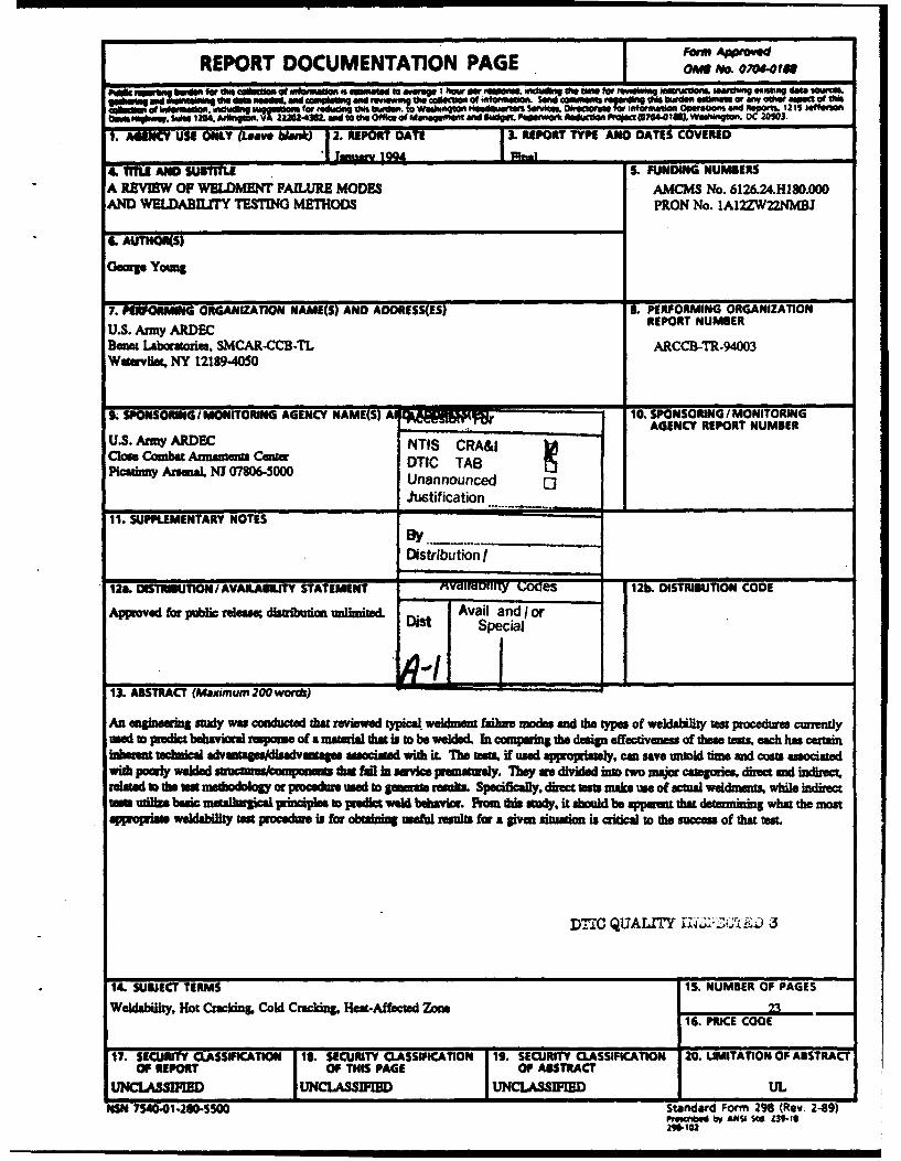
4. TLAND suEU S. FUNDING NUMBERSA REVIEW OF WELDME1T FAILURE MODES AMCMS No. 6M26.24.H180.000AND W.LDABILITY TESTING METHODS PRON No. IA12ZWI ZNMBJ
IL AUTHOR(S)
Goorg Youn
7. PfRFORM*G ORGANIZATION NAME(S) AND AOORESS(ES) 8. PERFORMING ORGANIZATION
U.S. Amy ARDEC REPORT NUMBER
Banea Labortories,. SMCAR-CCB-TL ARCCB-TR-94003Wsrvile. NY 1218994050
t SPONSORING /MONITORING AGENCY NAME(S) Al 1 10. SPONSORING / MONITORINGAGENCY REPORT NUMBER
U.S. Amy ARDEC NTIS CRA&ICase Combat Annausu CQuer DTIC TABPlcaaMy ArsenL, NJ 07DT&50TA
UnannouncedJuwtification
11. SUPPLEMENTARY NOTES
Distribution o,
12a. OISTRIBUTIONIAVAILABILITY STATEMENT vMYIIUUIII1y Coaes 12b. DISTRIBUTION CODE
Approved for public rleas diM'ibudax unlimited. Avail and I or
13. ABSTRACT (Maximum 200words)
An agmewg so*d was conductd that reviewd tical weldmms failure modes and the types of weldahility at proced e crendyusd to predict bdhvoa spame of a material that is to be welded. In compaing the dsign effectiveness of theae m, each has cermininhrent technic advalages aes assocated with iL The teN if used appropah, c save unold dme ad cost associated
IibMpoiywed 1, & fad•in. svice jaianly. hy1 ae dividd k two mao cago , dires rmid bdrecrelated to the test methodolog or pcedumr used to ganmni resul. Specifically, dirt tast make use of actual weldmert while indirecttan usilze besic mumilursical principles to pedkt weld beao. From this sudy, it shuld be appaet that deterumiig what the mostapprmq•a weldability tast poceduve Is for obasig sefl sulft for a iven uamon is cdtial o ft succes of that st.
DTIC QUALITY 12i1 iJ 3
14. SUBJECT TERMS 15. NUMBER OF PAGES
Weldability, Hot Cracking Cold Cracking, Heat-Affected Zone _ _ _1
16. PRICE CODE
17. SECURITY CLASSIICATION 13. SECURITY CLASSIFICATION 19. SECURITY CLASSIFICATION 20. UMITATION OF ABSTRACTOP REPORT OF THIS PAGE OF ABSTRACT
UNCLASSINIED I CL M JUNCLASSIFIED I UL
NSN 7S40-01-260-5SO0 Standard Form 298 (Rev. 2-89)P eg d b• A14SI iStd. Z39I1
TABLE OF CONTENTS
INTRODUCTION ................................................................. 1
DIRECT TESTS .................................................................. 2
INDIRECT TESTS ................................................................ 4
SU M M A RY ..................................................................... 5
REFERENCES ................................................................... 6
LIST OF ILLUSTRATIONS
1. An example of hot cracking in a fillet weld ......................................... 7
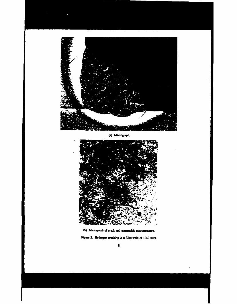
2. Hydrogen cracking in a fillet weld of 1040 steel ...................................... 8
3. Schematic and microstructure of lamellar tearing ...................................... 9
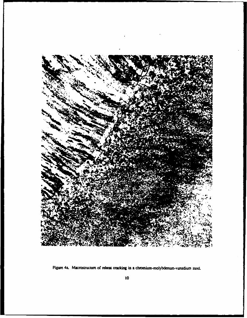
4a. Macrostructure of reheat cracking in a chromium-molybdenum.vanadium steel ................ 10
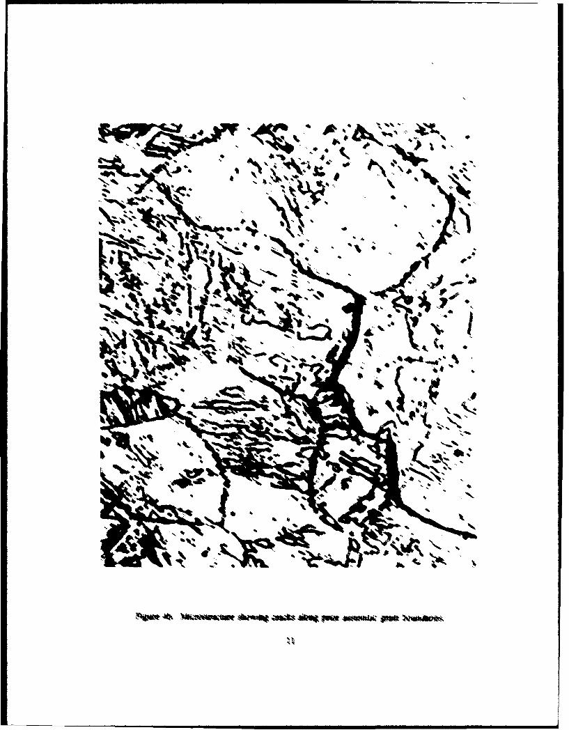
4b. Microstructure showing cracks along prior austenite grain boundaries ...................... 11
5. Schematic of the subscale varesoraint test .......................................... 12
6. Schematic of the spot varestraint test ............................................. 13
7. Schematic of the transvarestraint test ............................................. 14
8. Schematic of the Lehigh restraint test specimen ..................................... 15
9. Schematic of the tapered fin test specimen ......................................... 16
10. Schematic of the Houldcroft test specimen ......................................... 17
Ila. Schematic of free bend test apparatus showing initial bend fixturing ....................... 18
111b. Schematic of free bend test apparatus showing final bend fixturing ........................ 19
12. Schematic of the drop-weight test ............................................... 20
13. Schematic of the Gleeble apparatus ............................................ 21
14. Schematic of the cast-pin-tear test ............................................... 22
: : _- .- i
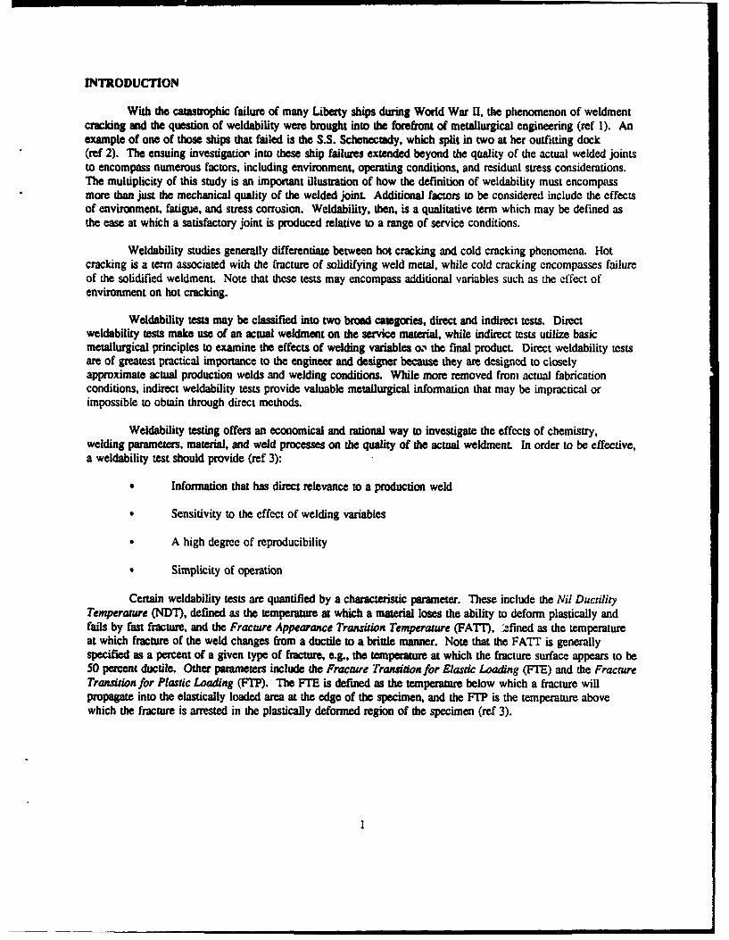
INTRODUCTION
With the catastrophic failure of many Liberty ships during World War U, the phenomenon of weldmentcracking and the question of weldability were brought into the forefront of metallurgical engineering (ref 1). Anexample of one of those ships that failed is the S.S. Schenectady, which split in two at her outfitting dock(ref 2). The ensuing investigatio' into these ship failures extended beyond the qaality of the actual welded jointsto encompass numerous factors, including environment, operating conditions, and residual stress considerations.The multiplicity of this study is an important illustration of how the definition of weldability must encompassmore than just the mechanical quality of the welded joint. Additional factors to be considered include the effectsof environment, fatigue, and stress corrosion. Weldability, then, is a qualitative term which may be defined asthe ease at which a satisfactory joint is produced relative to a range of service conditions.
Weldability studies generally differentiate between hot cracking and cold cracking phenomena. Hotcracking is a term associated with the fracture of solidifying weld metal, while cold cracking encompasses failureof the solidified weldment. Note that these tests may encompass additional variables such as the effect ofenvironment on hot cracking.
Weldability tests may be classified into two broad categories, direct and indirect tests. Directweldability tests make use of an actual weldment on the service material, while indirect tests utilize basicmetallurgical principles to examine the effects of welding variables o.% the final product. Direct weldability testsare of greatest practical importance to the engineer and designer because they are designed to closelyapproximate actual production welds and welding conditions. While more removed from actual fabricationconditions, indirect weldability tests provide valuable metallurgical information that may be impractical orimpossible to obtain through direct methods.
Weldability testing offers an economical and rational way to investigate the effects of chemistry,welding parameters, material, and weld processes on the quality of the actual weldment. In order to be effective,a weldability test should provide (ref 3):
* Information that has direct relevance to a production weld
0 Sensitivity to the effect of welding variables
0 A high degree of reproducibility
0 Simplicity of operation
Certain weldability tests are quantified by a characteristic parameter. These include the Nil DuctilityTemperature (NDT), defined as the temperature at which a material loses the ability to deform plastically andfails by fast fracture, and the Fracture Appearance Transition Temperature (FAT1), -fined as the temperatureat which fracture of the weld changes from a ductile to a brittle manner. Note that the FATI is generallyspecified as a percent of a given type of fracture, e.g., the temperature at which the fracture surface appears to be50 percent ductile. Other parameters include the Fracture Transition for Elastic Loading (FTE) and the FractureTransition for Plastic Loading (FMP). The FTE is defined as the temperature below which a fracture willpropagate into the elastically loaded area at the edge of the specimen, and the FTP is the temperature abovewhich the fracture is arrested in the plastically deformed region of the specimen (ref 3).
I1
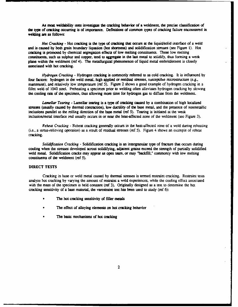
As most weldability teats investigate the cracking behavior of a weldment, the precise classification ofthe type of cracking occurring is of importance. Definitions of common types of cracking failure encountered inwelding awe as follows:
Hot Cracking - Hot cracking is the type of cracking that occurs at the liquid/solid interface of a weldand is caused by both grain boundary liquation (hot shortness) and solidification stresses (see Figure 1). Hotcracking is promoted by chemical segregation effects of low melting constituents. These low meltingconstituents, such as sulphur and copper, tend to aggregate in the last metal to solidify, thus forming a weakplane within the weldment (ref 4). The metallurgical phenomenon of liquid metal embritdement is closelyassociated with hot cracking.
Hydrogen Cracking - Hydrogen cracking is commonly referred to as cold cracking. It is influenced byfour factors: hydrogen in the weld metal, high applied or residual stresses, susceptibie microstructure (e.g.,martensite), and relatively low temperature (ref 5). Figure 2 shows a good example of hydrogen cracking in afillet weld of 1040 steel. Preheating a specimen prior to welding often alleviates hydrogen cracking by slowingthe cooling rate of the specimen, thus allowing more time for hydrogen gas to diffuse from the weldmenL
Lamellar Tearing - Lamellar tearing is a type of cracking caused by a combination of high localizedstresses (usually caused by thermal contraction), low ductility of the base metal, and the presence of nonmetallicinclusions parallel to the rolling direction of the base metal (ref 5). Tearing is initiated at the weakinclusion/metal interface and usually occurs in or near the heat-affected zone of the weldment (see Figure 3).
Reheat Cracking - Reheat cracking generally occurs in the heat-affected zone of a weld during reheating(i.e., a stress-relieving operation) as a result of residual stresses (ref 5). Figure 4 shows an example of reheatcracking.
Solidification Cracking - Solidification cracking is an intergranular type of fracture that occurs duringcooling when the stresses developed across solidifying, adjacent grains exceed the strength of partially solidifiedweld metal. Solidification cracks may appear as open tears, or may "backfill," commonly with low meltingconstituents of the weldment (ref 5).
DIRECT TESTS
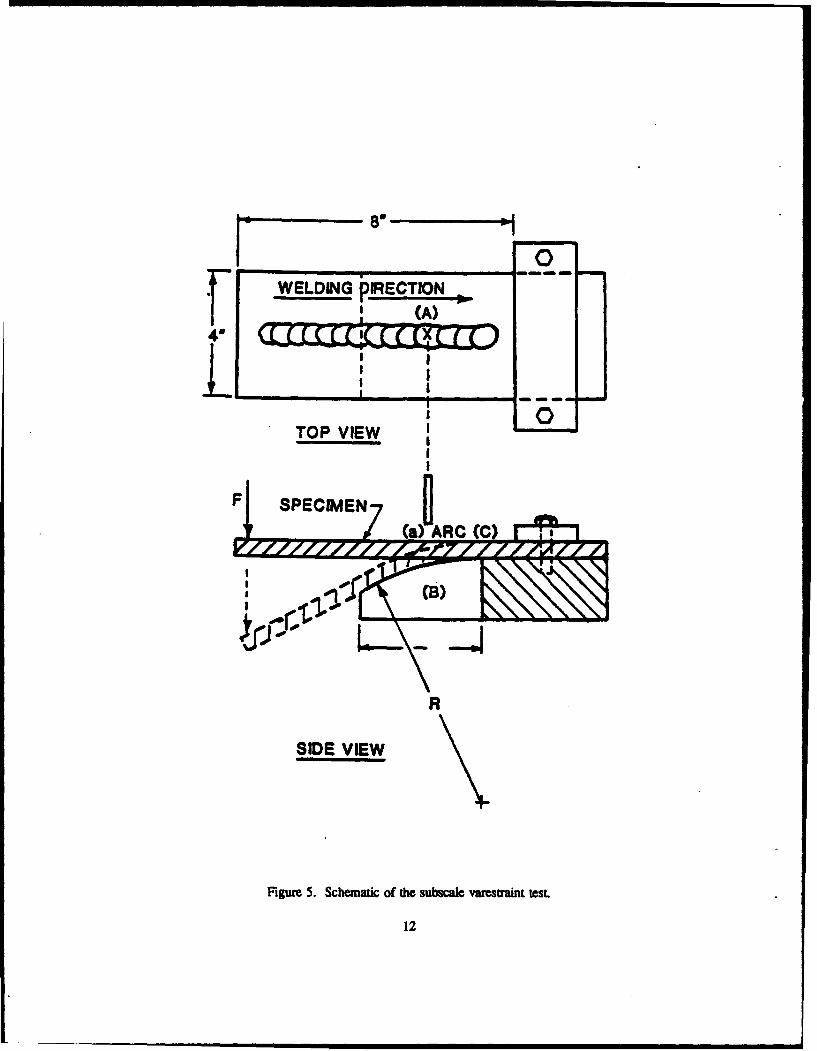
Cracking in base or weld metal caused by thermal stresses is termed restraint cracking. Restraint testsanalyze hot cracking by varying the amount of restraint a weld experiences, while the cooling effect associatedwith the mass of the specimen is held constant (ref 3). Originally designed as a test to determine the hotcracking sensitivity of a base material, the varestraint test has been used to study (ref 6):
* The hot cracking sensitivity of filer metals
The effect of alloying elements on hot cracking behavior
The basic mechanisms of hot cracking
2
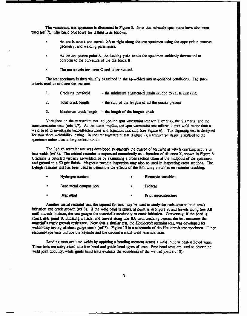
The varestrait test apparatus is iilustrated in Figure 5. Note that subscale specimens have also beenused (ref 7). The basic procedure for testing is as follows:
An arc is struck and travels left to right along the test specimen using the appropriate process,geometry, and welding parameters.
As the arc passes point A, the loading yoke bends the specimen suddenly downward to
conform to the curvature of the die block B.
The arc travels int, area C and is terminated.
The test specimen is then visually examined in the as-welded and as-polished conditions. The threecriteria used to evaluate the test are:
1. Cracking threshold - the minimum augmented strain needed to cause cracking
2. Total crack length - the sum of the lengths of all the cracks present
3. Maximum crack length - tht. length of the longest crack
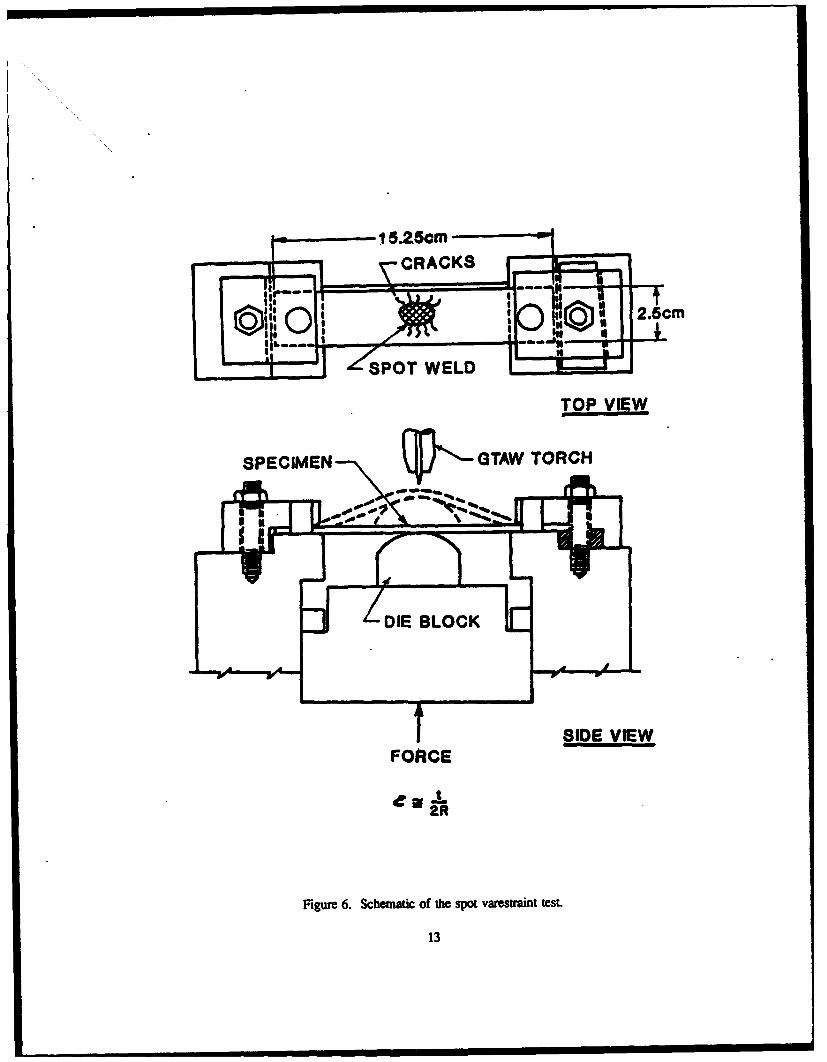
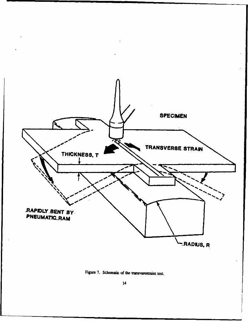
Variations on the varestraint test include the spot varestraint test (or Tigmajig), the Sigmajig, and thetransvarestraint tests (refs 1,7). As the name implies, the spot varestraint test utilizes a spot weld rather than aweld bead to investigate heat-affected zone and liquation cracking (see Figure 6). The Sigmajig test is designedfor thin sheet weldability testing. In the transvarestraint test (Figure 7), a transverse strain is applied to thespecimen rather than a longitudinal strain.
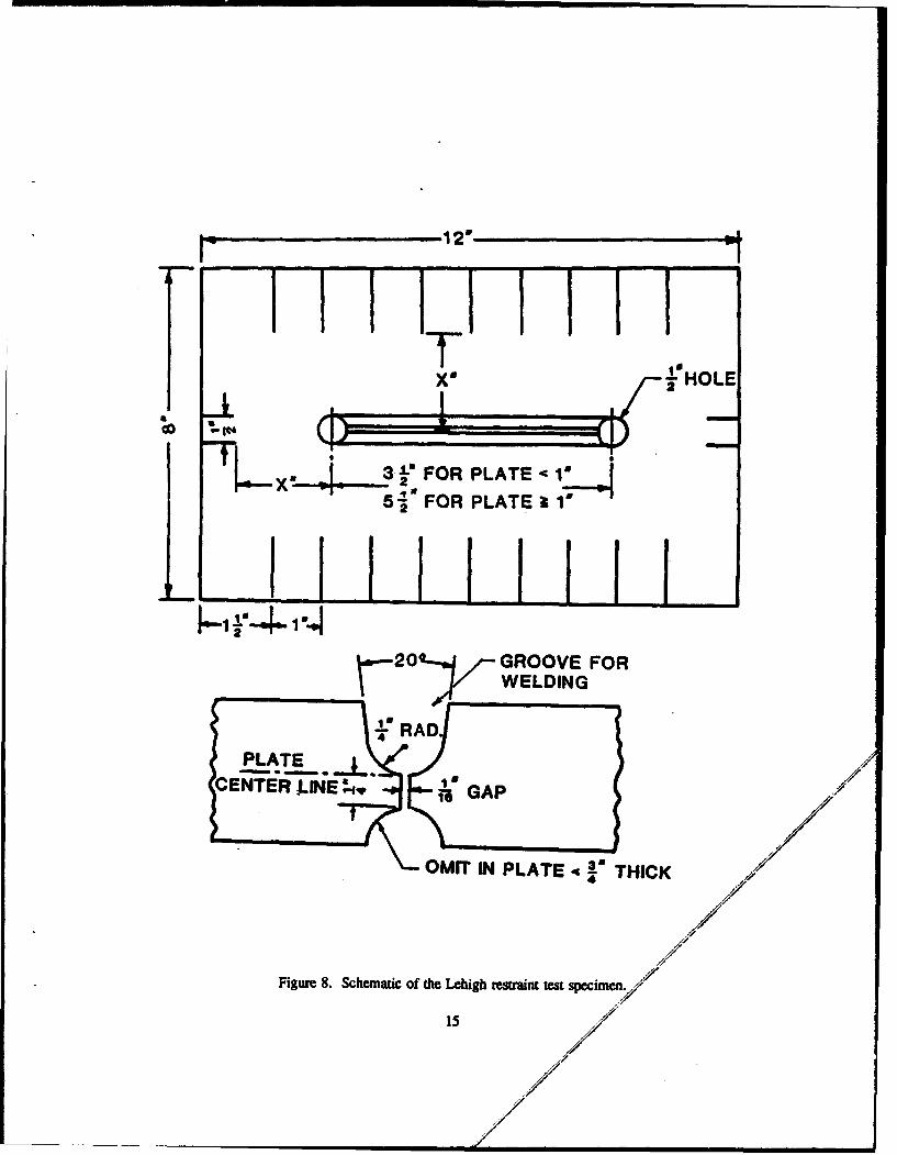
The Lehigh restraint test was developed to quantify the degree of restraint at which cracking occurs inbutt welds (ref 3). The critical restraint is expressed numerically as a function of distance X, shown in Figure 8.Cracking is detected visually as-welded, or by examining a cross section taken at the midpoint of the specimenand ground to a 50 grit finish. Magnetic particle inspection may also be used in inspecting cross sections. TheLehigh restraint test has been used to determine the effects of the following variables on restraint cracking:
Hydrogen content Electrode variables
Base metal composition Preheat
Heat input Prior microstructure
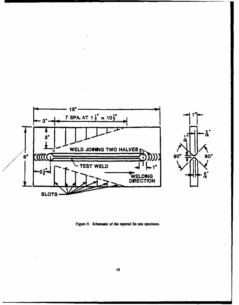
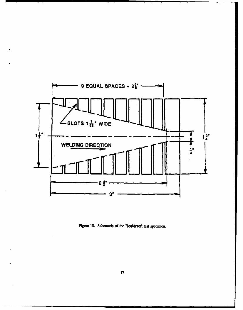
Another useful restraint test, the tapered fin test, may be used to study the resistance to both crackinitation and crack growth (ref 3). If the weld bead is struck at point A in Figure 9, and travels along line ABuntil a crack initiates, the test gauges the material's sensitivity to crack initiation. Conversely, if the bead isstruck near point B, initiating a crack, and travels along line BA until cracking ceases, the test measures thematerial's crack growth resistance. Note that a similar test, the Houldcroft restraint test, was developed forweldability testing of sheet gauge steels (ref 3). Figure 10 is a schematic of the Houldcroft test specimen. Otherrestraint-type tests include the keyhole and the circumferential-weld restraint tests.
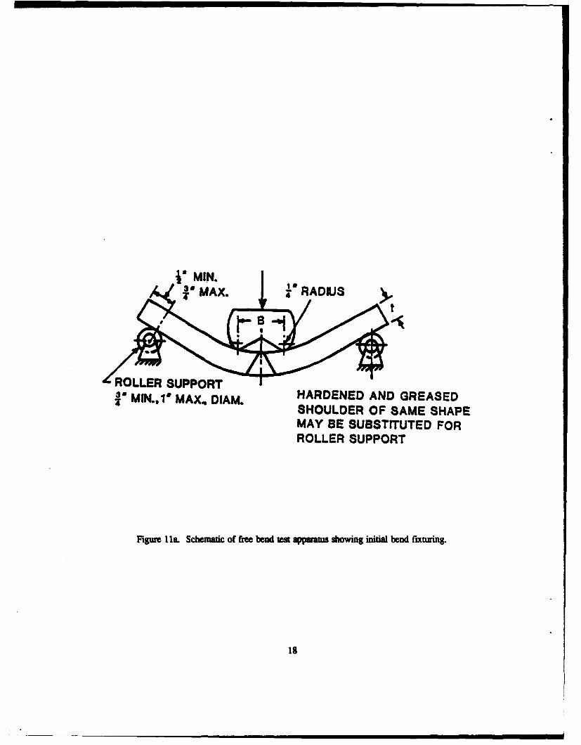
Bending tests evaluate welds by applying a bending moment across a weld joint or heat-affected zone.These tests are categorized into free bend and guide bend types of tests. Free bend tests are used to determineweld joint ductility, while guide bend tests evaluate the soundness of the welded joint (ref 8).
3
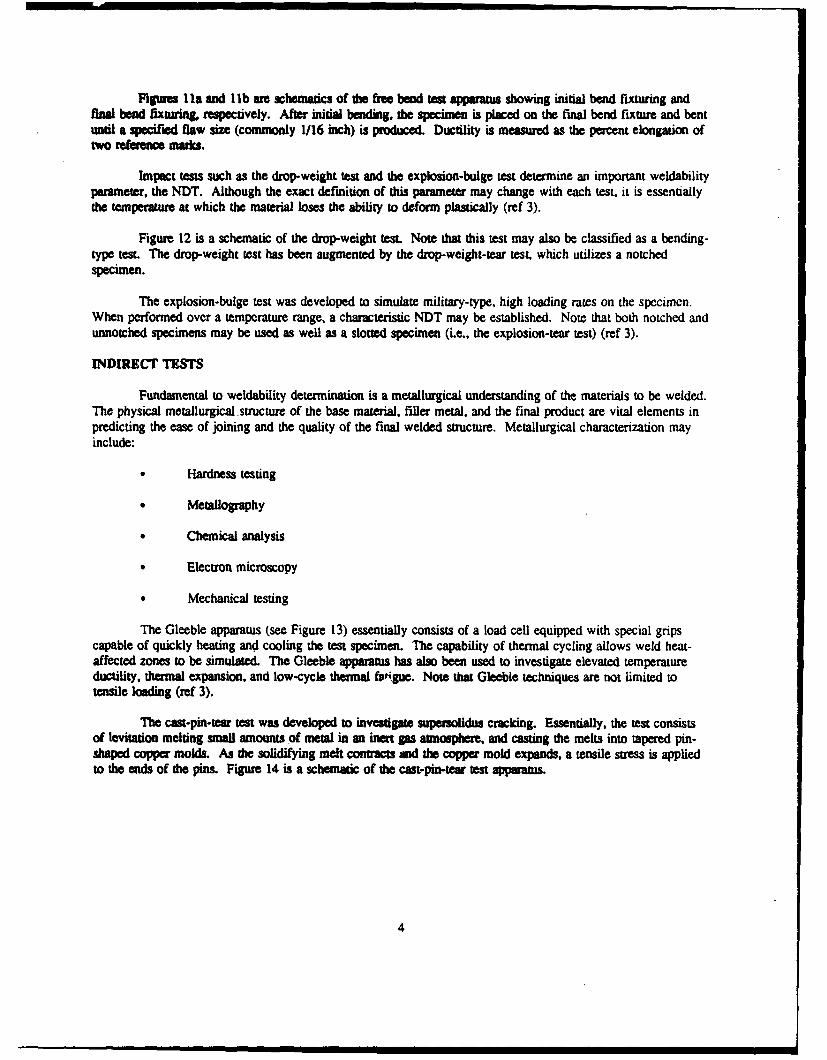
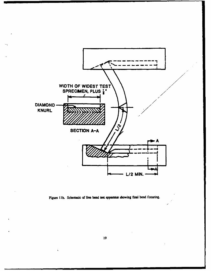
Figures Ila and lib are schematics of the free bend ten appaauus showing initial bend fixturing andfinal bend fixtur& ec•tively. After initial bending. the specimen is placed on the final bend fixture and bentuntil a specified flaw size (commonly 1/16 inch) is produced. Ductility is measured as the percent elongation oftwo rferen masks.
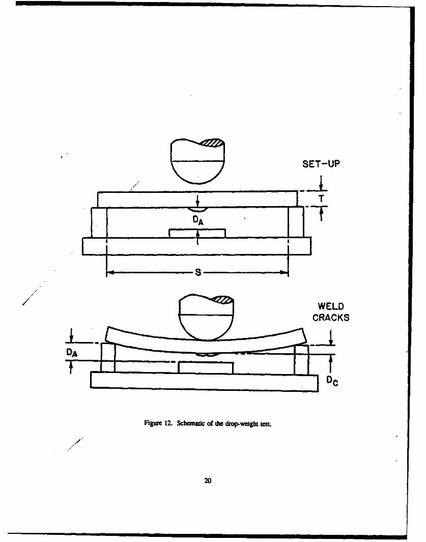
Impact tests such as the drop-weight test and the explosion-bulge test determine an important weldabilityparameter, the NDT. Although the exact definition of this parameter may change with each test, it is essentiallythe temperature at which the material loses the ability to deform plastically (ref 3).
Figure 12 is a schematic of the drop-weight test. Note that this test may also be classified as a bending-type test. The drop-weight test has been augmented by the drop-weight-tear test, which utilizes a notchedspecimen.
The explosion-bulge test was developed to simulate military-type, high loading rates on the specimen.When performed over a temperature range, a characteristic NDT may be established. Note that both notched andunnotched specimens may be used as well as a slotted specimen (Le., the explosion-tear test) (ref 3).
INDIRECT TESTS
Fundamental to weldability determination is a metallurgical understanding of the materials to be welded.The physical metallurgical structure of the base material, filler metal, and the final product are vital elements inpredicting the ease of joining and the quality of the final welded structure. Metallurgical characterization mayinclude:
Hardness testing
* Metallography
* Chemical analysis
* Electron microscopy
* Mechanical testing
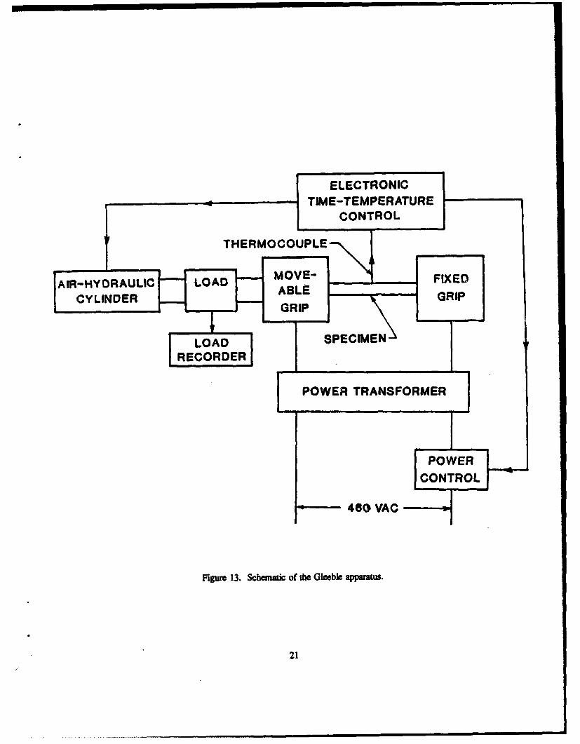
The Gleeble apparatus (see Figure 13) essentially consists of a load cell equipped with special gripscapable of quickly heating and cooling the test specimen. The capability of thermal cycling allows weld heat-affected zones to be simulated. The Gleeble apparatus has also been used to investigate elevated temperatureductility, thermal expansion, and low-cycle thermal f9figue. Note that Gleeble techniques are not limited totensile loading (ref 3).
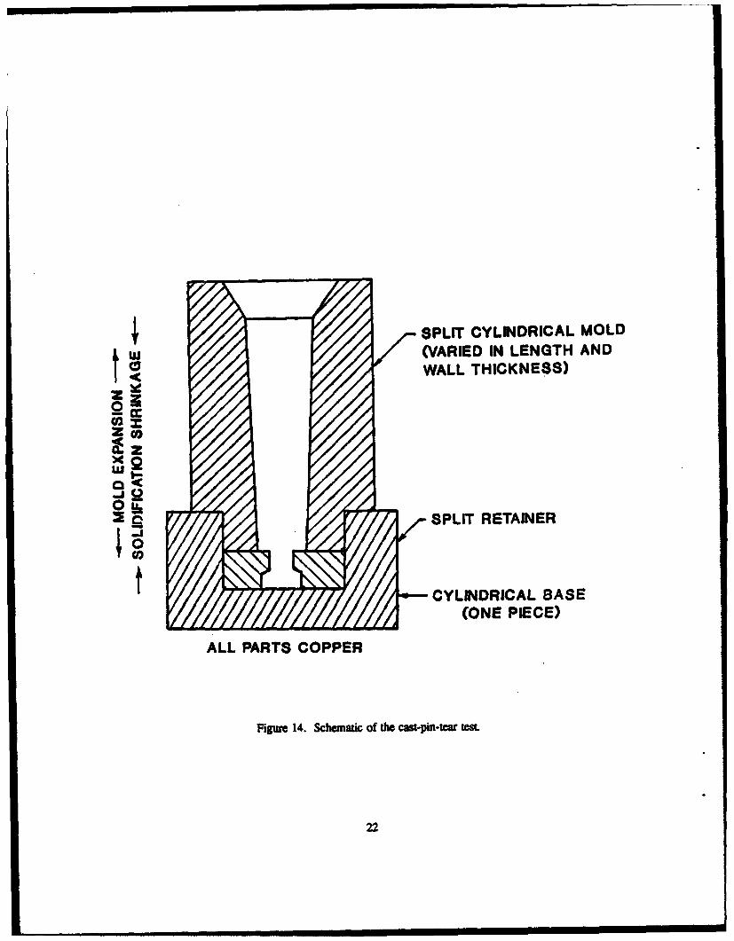
The cast-pin-tewa test was developed to investigate supersolidus cracking. Essentially, the test consistsof levitation melting small amounts of metal in an inert gas atmosphere, and casting the melts into tapered pin-shaped copper molds. As the solidifying melt contracts and the copper mold expands, a tensile stress is appliedto the ends of the pins. Figure 14 is a schematic of the cast-pin-tear test apparatus.
4
SUMMARY
As was evident from the cawstrophic failure of many Liberty ships during World War II, dhephenomenon of weldment cracking is of tremendous engineering imporance. One manner in which weldmentquality can be investigated is through weldability testing techniques. Weldability testing offers an economic andscientific way of studying the effects of numerous factors on the quality of the final weldment. Direct testingmethods, which utilize an actual weld on service material, offer the closest correlation to a production weld,while indirect tests may reveal information impossible to obtain by direct methods. Direct testing methods canbe subdivided into restraint, bend, and impact types of tests. Restraint tests investigate the effect of strain on hotcracking behavior, bend tests quantify weld ductility, and impact tests generally determine a characteristictemperature where the fracture mode of the weldment changes. Augmenting direct tests, indirect testing methodshelp characterize a weldment by providing important metallurgical information that is difficult or impossible toobtain through direct testing methods.
5
REFERENCES
1. R.G. Baker, RI. Dolby. and F. Waikinson, "The Assement of Cracking Problems," Weldability ofSouctural and Pressure Vessel Steels, Corerence Proceedings - Volume I. The Papers, The WeldingInstitu•e, Cambridge, U.L, 1970.
2. The Design and Methods of Cons., uction of Welded Steel Merchant V essels, U.S. Government PrintingOffice, Washington, D.C.. W,,.
3. Robert D. Stout and W. O'Orville Doty, Weldabilry of Steels, Welding Research Council, New York,1978.
4. V.J. Collagelo and F.A. Heiser, Analysis of Metallurgical Failures, John Wiley & Sons, New York,1974.
5. Sindou Kou, Welding Metallurgy, John Wiley & Sows, New York, 1987.
6. W.F. Savage and C.D. Lundin, Application of the Varestraint Technique to the Study of Weldability,Welding Research Supplement, 1966.
7. W.A. Baeslack, S. Ernst, and J.C. Lippold, "Weldability of High Strength, Low-Expansion Supcralloys,"Edison Welding Institute, Columbus, OH, June 1988.
8. Boniface E. Rossi, Welding Engineering, McGraw-Hill, New York, 1954.
6
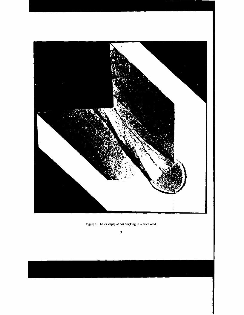
Figure 1. An example of hot cracking in a fillet weld.
7
at- F iy.,
(b) Microgpup of crack and mantenuitic microauicunire
Figu 2. Hydrge crackin in a Miet weld of 1040 steel
Ooa•
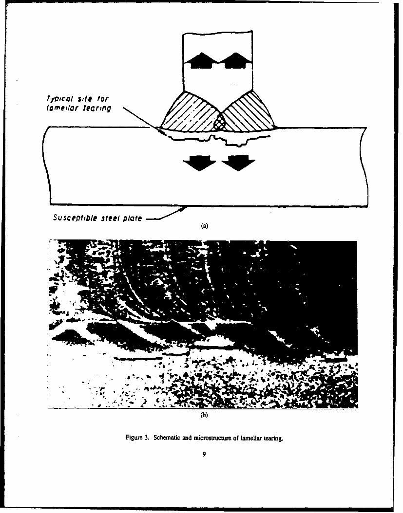
T7YICol site forlamellar tearing
Susceptible steel plate(a)
.~A %i P"-
I~
AL
(b)
Figure 3. Schematic and microstructure of lamellar tearing.
9
I i II IIi i APO
m IA.',,
.o ..
T.,
Fig=r 4a. Mw~rosarumm of rehea wct m a• s €lomium-molylbdelurm-varladium steel.
10
4b
4 jý 0
- -
44%
\4
q44
# ý4
fA-44
* Ok
WELDING DIRECTION(A)
II
Ij -I -,
I 0TOP VIEW
F SPECIMEN ( C('
R
SIDE VIEW
Figure 5. Schematic of the subscale varesatrai teSL
12
all1"10 2.5cm
rl SPOT WELD
TOP VIEW
SPECIMEN •GTAW TORCH
F 4
-DIE BLOCK
SIDE VIEW
FORCE
Figure 6. Schematic of the spot varestraint tesLt
13
S~SPECIMEN
TRANSVERSE. STRAIN
S, THICKNESS, T
Figure 7. Schematic of the trraesrit teSt.
14
• ,.. . a H .I
,12"
X" ("HOLE
X" - 3-f FOR PLATE < 1
-5-1' FOR PLATE I1i_ i 11!20 GROOVE FOR
WELDING
RRAD-
, ENTER JLINE :+w GAP ,37/
OMIT IN PLATE , ; THICK
Figure 8. Schematic of the Lehigh restraint test specime/
1/
15 /"
/,//
3",,• 7 • SPA. AT 11" 10½ -I-
1
,
1* 16
I- WELD JOINING TWO HALVES 900
44e, " •90"0 90 "
r'2 31-] •, ~~WELDING - "l
_•_j DIRECTION
SLOTS
Figure 9. Schematic of fte taperd fin test specimen.
16
9 EQUAL SPACES , 2r
SLOTS I WIDE
4WELDING DIRECTION
• 4
Figw= 10. Sch•matic of the Houldcroft ten specimen.
17
MIN.3MAX.DIS
ROLLER SUPPORT38 MIN., MAX., DIAM. HARDENED AND GREASEDSHOULDER OF SAME SHAPE
MAY BE SUBSTITUTED FORROLLER SUPPORT
Figure la. Schematic of free bend mt apparaws showing initial bend fixtuing.
18
S/"
WIDTH OF WIDEST TESTSPRECIMEN, PLUS "
DIAMONDKNURL
TA
"L/2 MIN.
Figure I lb. Schemaic of free bend rest appffar showing final bend fixuring.
19
/ SET-UP
I' I i I - - I4 T___I'DA
~ S |
/WELDS~CRACKS
S. .. .. 7 DC
Figure 12. Schenmaic of the drop-weight test.
20
ELECTRONIC
TIME-TEMPERATURECONTROL
THERMOCOUPLE
AIR-HYDRAULIC LOAD MFIXEDCYLINDER ABLE GRIP-
GGRIP
LOA! SPECIMENDE]DRECORDER
L POWER TRANSFORMER
[OWER
CONTROL
460 VAC
Figure 13. Schematic of the Gleeble apparats.
21
I SPLIT CYLINDRICAL MOLD(VARIED IN LENGTH ANDWALL THICKNESS)
Z z
Zcoqc
0ix
_Q /SPLIT RETAINER
CYLINDRICAL BASE(ONE PIECE)
ALL PARTS COPPER
Figure 14. Schematic of the cast-pin-tear tesL
22
TECHNICAL REPORT INTERNAL DISTRIBUTION LIST
NO. OFCOPIES
CHIEF, DEVELOPMENT ENGINEERING DIVISIONATITN: SMCAR-CCB-DA 1
-DC I-DI I-DR I-DS (SYSTEMS) 1
CHIEF, ENGINEERING DIVISIONATIN: SMCAR-CCB-S 1
-SD I-SE 1
CHIEF, RESEARCH DIVISIONATTN: SMCAR-CCB-R 2
-RA I-RE 1-RM 1-RP 1-RT 1
TECHNICAL LIBRARYATFN: SMCAR-CCB-TL 5
TECHNICAL PUBLICATIONS & EDITING SECTIONATTN: SMCAR-CCB-TL 3
OPERATIONS DIRECTORATEATTN: SMCWV-ODP-P 1
DIRECTOR, PROCUREMENT & CONTRACTING DIRECTORATEATTN: SMCWV-PP 1
DIRECTOR, PRODUCT ASSURANCE & TEST DIRECTORATEATTN: SMCWV-QA 1
NOTE: PLEASE NOTIFY DIRECTOR, BEN"T LABORATORIES, ATTN: SMCAR-CCB-TL OF ADDRESS CHANGES.
TECHNICAL REPORT EXTERNAL DISTRIBUTION LIST
NO. OF NO. OFCOPIES COPIES
ASST SEC OF THE ARMY COMMANDERRESEARCH AND DEVELOPMENT ROCK ISLAND ARSENALATTN: DEPT FOR SCI AND TECH 1 ATITN: SMCRI-ENMTHE PENTAGON ROCK ISLAND, EL 61299-5000WASHINGTON, D.C. 20310-0103
MIAC/CINDASADMINISTRATOR PURDUE UNIVERSITYDEFENSE TECHNICAL INFO CENTER 12 P.O. BOX 2634ATTN: DTIC-FDAC WEST LAFAYETTE, IN 47906CAMERON STATIONALEXANDRIA, VA 22304-6145 COMMANDER
U.S. ARMY TANK-AUTMV R&D COMMANDCOMMANDER ATTN: AMSTA-DDL (TECH LIBRARY) 1U.S. ARMY ARDEC WARREN, MI 48397-5000ATTN- SMCAR-AEE 1
SMCAR-AES, BLDG. 321 1 COMMANDERSMCAR-AET-O, BLDG. 35 IN 1 U.S. MILITARY ACADEMYSMCAR-CC 1 ATIN: DEPARTMENT OF MECHANICS 1SMCAR-FSA 1 WEST POINT, NY 10966-1792SMCAR-FSM-E 1SMCAR-FSS-D, BLDG. 94 1 U.S. ARMY MISSILE COMMANDSMCAR-IMI-L (STINFO) BLDG. 59 2 REDSTONE SCIENTIFIC INFO CENTER 2
PICATINNY ARSENAL, NJ 07806-5000 ATTN: DOCUMENTS SECTION, BLDG. 4484REDSTONE ARSENAL, AL 35898-5241
DIRECTORU.S. ARMY RESEARCH LABORATORY COMMANDERATTN: AMSRL-DD-T, BLDG. 305 1 U.S. ARMY FOREIGN SCI & TECH CENTERABERDEEN PROVING GROUND, MD ATTN: DRXST-SD 1
21005-5066 220 7TH STREET, N.E.CHARLOTTESVILLE, VA 22901
DIRECTORU.S. ARMY RESEARCH LABORATORY COMMANDERATrN: AMSRL-WT-PD (DR. B. BURNS) 1 U.S. ARMY LABCOMABERDEEN PROVING GROUND, MD MATERIALS TECHNOLOGY LABORATORY
21005-5066 ATIN: SLCMT-IML (TECH LIBRARY) 2WATERTOWN, MA 02172-0001
DIRECTORU.S. MATERIEL SYSTEMS ANALYSIS ACTV COMMANDERATTN: AMXSY-MP 1 U.S. ARMY LABCOM, ISAABERDEEN PROVING GROUND, MD ATTN: SLCIS-IM-TL 1
21005-5071 2800 POWER MILL ROADADELPHI, MD 20783-1145
NOTE: PLEASE NOTIFY COMMANDER, ARMAMENT RESEARCH, DEVELOPMENT, AND ENGINEERING CENTER, U.S.ARMY AMCCOM, ATIN: BEN•t LABORATORIES, SMCAR-ccB-T, WATERVUET, NY 12189.4050 OF ADDRESS CHANGES
TECHNICAL REPORT EXTERNAL DISTRIBUTION LIST (CONT-D)
NO. OF NO. OFCOIES COPIES
COMMANDER COMMANDERU.S. ARMY RESEARCH OFFICE AIR FORCE ARMAMENT LABORATORYATI'N: CHIEF, IPO 1 ATTN: AFATLIMNP.O. BOX 12211 EGLIN AFB, FL 32542-5434RESEARCH TRIANGLE PARK, NC 27709-2211
COMMANDERDIRECTOR AIR FORCE ARMAMENT LABORATORYU.S. NAVAL RESEARCH LABORATORY ATTN: AFATL/MNFATTN: MATERIALS SCI & TECH DIV 1 EGLIN AFB, FL 32542-5434
CODE 26-27 (DOC LIBRARY) 1WýýSHINGTON, D.C. 20375
NOTE PLEASE NOTIFY COMMANDER, ARMAMENT RESEARCH, DEVELOPMENT, AND ENGINEERING CENTER, U.S.ARMY AMCCOM, ATlTN. BENtT LABORATORIES, SMCAR-CCB-TL, WATERVLIET, NY 12189.4050 OF ADDRESSCHANGES.