Embed Size (px)
Citation preview
energyequipsys/ Vol 2/ 2014/ 5-24
Energy Equipment and Systems
www.energyequipsys.com
Review Paper
A review on fatigue design of heavy section EN-GJS-400-18-LT ductile iron wind turbine castings
Mehdi Shirania*
Gunnar Härkegård b
a
Subsea R&D Institute, Isfahan
University of Technology b Department of Engineering Design
and Materials, Norwegian university of science and technology
ABSTRACT
A comprehensive review of fatigue behavior and fatigue design of heavy section wind turbine castings made of ductile iron EN-GJS-400-18-LT is performed. Common metallurgical defects that are affecting fatigue behavior of this material were studied. Review of different researches on quantitative effect of chunky graphite and micro structure on fatigue behavior of EN-GJS-400-18-LT was performed. Finally, safe life design and damage tolerant design of heavy section wind turbine cast iron components were reviewed and compared with each other. It is tried to cover all the required points that should be considered in fatigue design of large EN-GJS-400-18-LT wind turbine castings.
Article history:
Received 24 November 2013 Accepted 27 January 2014
Keywords: Defect, Ductile cast iron, EN-GJS-400-18-LT, Fatigue design, Wind turbine.
1. Introduction The sharp increase in energy consumption and oil price in recent years, also the global warming due to greenhouse gases call for a sustainable energy resource that decreases the energy dependence of the world's largest and fastest-growing economies on oil and gas, also it does not create more co2, pollution. Wind power is a renewable, predictable and clean source of energy.
The wind power industry has been growing astonishingly in recent years. It is expected that wind power share of global power consumption will grow to at least 10% by 2020. The targets for renewable energy in the EU and China will account for 20% and 15%, respectively, in 2020 [1].These targets mean that installed capacity is set to rise from 200,000 MW in 2012 [2] to at least 1,000,000 MW in 2020, which means annual growth of more than 20%. Currently, wind power is the best option for reducing CO2
*Corresponding author: Subsea R&D Institute, Isfahan University of Technology E-mail address: [email protected], (Mehdi Shirani)
emissions. One V90-3.0 MW wind turbine can save the
atmosphere from more than 5,000 tons of CO2 emissions every year [3].
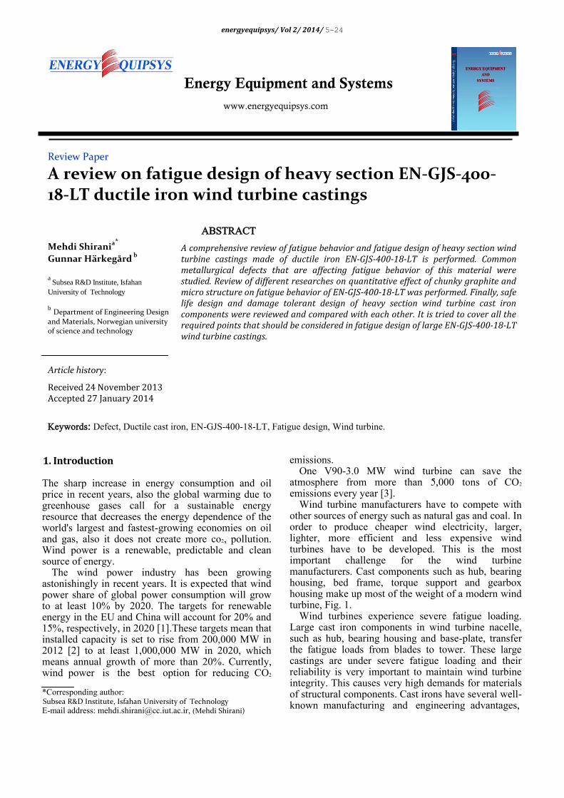
Wind turbine manufacturers have to compete with other sources of energy such as natural gas and coal. In order to produce cheaper wind electricity, larger, lighter, more efficient and less expensive wind turbines have to be developed. This is the most important challenge for the wind turbine manufacturers. Cast components such as hub, bearing housing, bed frame, torque support and gearbox housing make up most of the weight of a modern wind turbine, Fig. 1.
Wind turbines experience severe fatigue loading. Large cast iron components in wind turbine nacelle, such as hub, bearing housing and base-plate, transfer the fatigue loads from blades to tower. These large castings are under severe fatigue loading and their reliability is very important to maintain wind turbine integrity. This causes very high demands for materials of structural components. Cast irons have several well-known manufacturing and engineering advantages,
6 Mehdi Shirani & Gunnar Härkegård / energyequipsys/Vol 2/ 2014
a) b)
Fig. 1. Typical Ductile Iron (DI) castings for windmills a) a wind turbine hub, b) a wind turbine bed frame
including low manufacturing and good performance characteristics, such as wear resistance and vibration damping. Because of a larger content of free carbon and higher silicon content, graphitic cast irons have the greatest fluidity and the least shrinkage of any ferrous metals. Spheroid graphite cast iron EN-GJS-400-18-LT, former designation German DIN 1693 [4], Grade GGG 40.3 is the material of choice for many of the world major wind turbine manufacturers. To have larger, lighter, more efficient and less expensive wind turbines, the cast components should be optimized with respect to fatigue life. Thus, good knowledge of fatigue behaviour and fatigue design of large EN-GJS-400-18-LT castings is required.
In this paper, first a brief review of ductile cast iron is performed. Then metallurgical defects which affect the fatigue behaviour of ductile cast iron are reviewed. It is tried to evaluate the influence of chunky graphite and microstructure on the fatigue behaviour of EN-GJS-400-18-LT. In the last section, a review of safe life design and damage tolerant design of an EN-GJS-
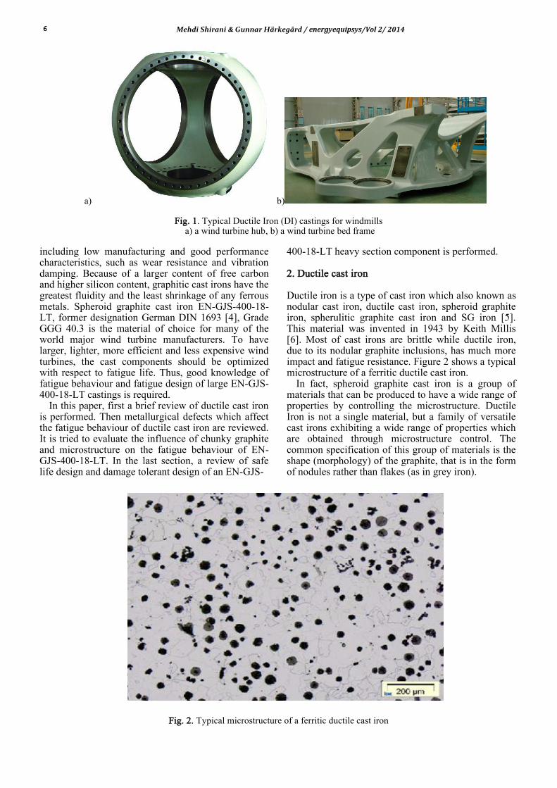
400-18-LT heavy section component is performed. 2. Ductile cast iron Ductile iron is a type of cast iron which also known as nodular cast iron, ductile cast iron, spheroid graphite iron, spherulitic graphite cast iron and SG iron [5]. This material was invented in 1943 by Keith Millis [6]. Most of cast irons are brittle while ductile iron, due to its nodular graphite inclusions, has much more impact and fatigue resistance. Figure 2 shows a typical microstructure of a ferritic ductile cast iron.
In fact, spheroid graphite cast iron is a group of materials that can be produced to have a wide range of properties by controlling the microstructure. Ductile Iron is not a single material, but a family of versatile cast irons exhibiting a wide range of properties which are obtained through microstructure control. The common specification of this group of materials is the shape (morphology) of the graphite, that is in the form of nodules rather than flakes (as in grey iron).
Fig. 2. Typical microstructure of a ferritic ductile cast iron
Mehdi Shirani & Gunnar Härkegård / energyequipsys/Vol 2/ 2014 7
This nodular shape is inhibiting the creation of cracks and act as "crack-arresters" providing the enhanced ductility that gives the alloy its name [3].
Ductile iron consists of primarily two materials: a steel matrix surrounding graphitic nodules. The steel matrix can be ferritic, pearlitic or martensitic, or a combination of any two. The majority of ductile castings are generally ferritic with less than 10% pearlite. The matrix in which the graphite nodules are dispersed plays a significant role in determining mechanical properties.
Wind turbine cast iron components are under heavy fatigue loading. The fatigue properties of ductile cast irons are based on spheroid graphite in pearlitic or ferritic matrix. Sometimes different graphite morphologies such as vermicular, spiky, coral, exploded and chunky graphite have been observed to form in thermal centres of heavy ductile cast iron sections during solidification. Metallurgical defects can severely deteriorate fatigue strength of ductile cast iron.
In fatigue design of wind turbine cast iron components, metallurgical defects such as vermicular, spiky, coral, exploded and chunky graphite are not acceptable on the component surface and should be removed from the surface and if not possible, the component is mostly rejected. Thus, metallurgical defects in ductile iron can be very costly to the foundry, not only because the part has to be remade or rectified, but due to the unfortunate fact that many defects are not revealed on the surface until after the expensive machining stage. Care in the selection of raw materials, good process control in the melting stage and proper metal handling procedures will go a long way to the prevention of defects.
3. Common metallurgical defects in ductile cast iron In heavy thick-walled (>100mm) components, the desired spherical morphology of the precipitated graphite often degenerates to several different morphologies such as vermicular, spiky, coral, exploded and chunky. Common defects may be divided into two basic categories [7]: Those related to nodule shape and size, such as
compacted graphite structures, exploded and chunky graphite, graphite floatation, spiky graphite and nodule alignment.
Those related to inclusions/abnormalities, such as flake graphite, slag inclusions, carbides, gas pores and shrinkage cavities.
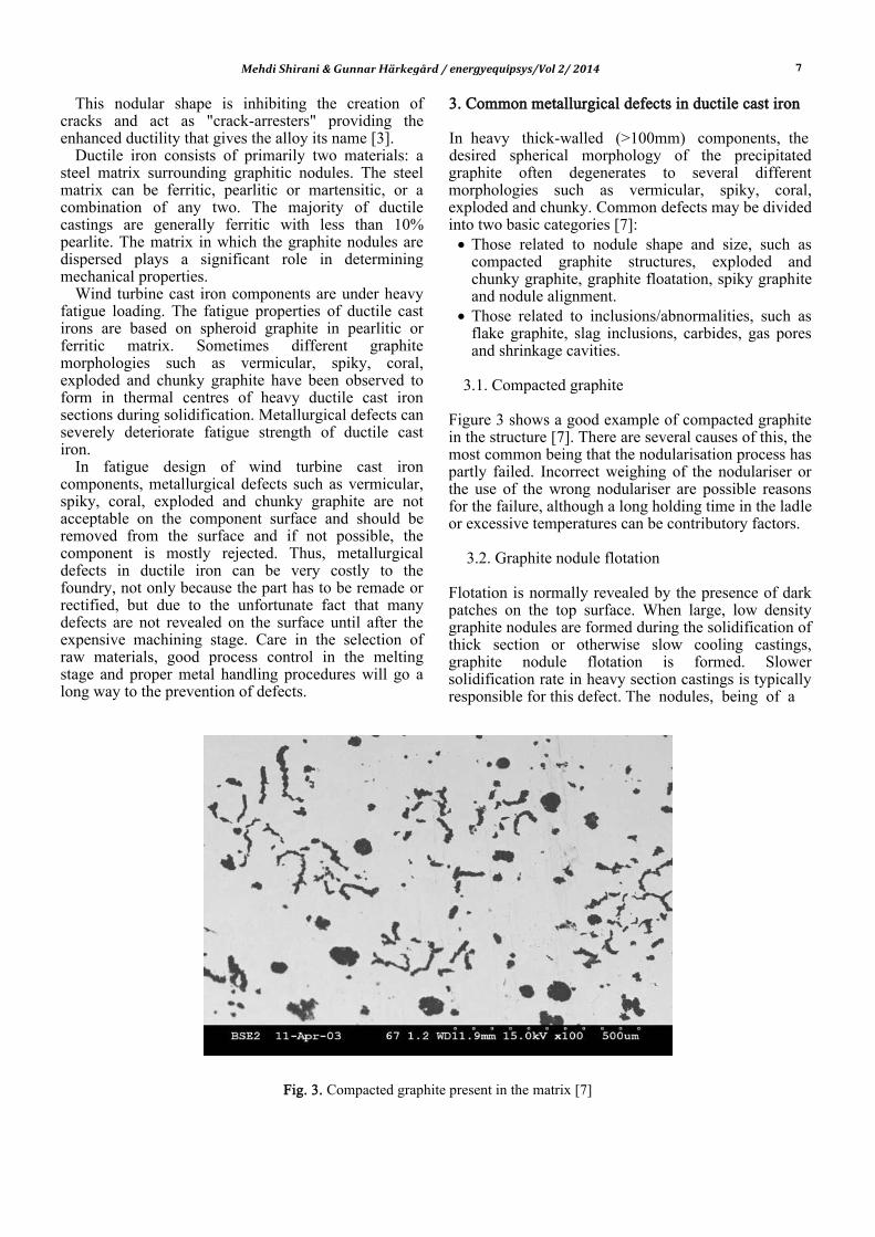
3.1. Compacted graphite
Figure 3 shows a good example of compacted graphite in the structure [7]. There are several causes of this, the most common being that the nodularisation process has partly failed. Incorrect weighing of the nodulariser or the use of the wrong nodulariser are possible reasons for the failure, although a long holding time in the ladle or excessive temperatures can be contributory factors.
3.2. Graphite nodule flotation
Flotation is normally revealed by the presence of dark patches on the top surface. When large, low density graphite nodules are formed during the solidification of thick section or otherwise slow cooling castings, graphite nodule flotation is formed. Slower solidification rate in heavy section castings is typically responsible for this defect. The nodules, being of a
Fig. 3. Compacted graphite present in the matrix [7]
8 Mehdi Shirani & Gunnar Härkegård / energyequipsys/Vol 2/ 2014
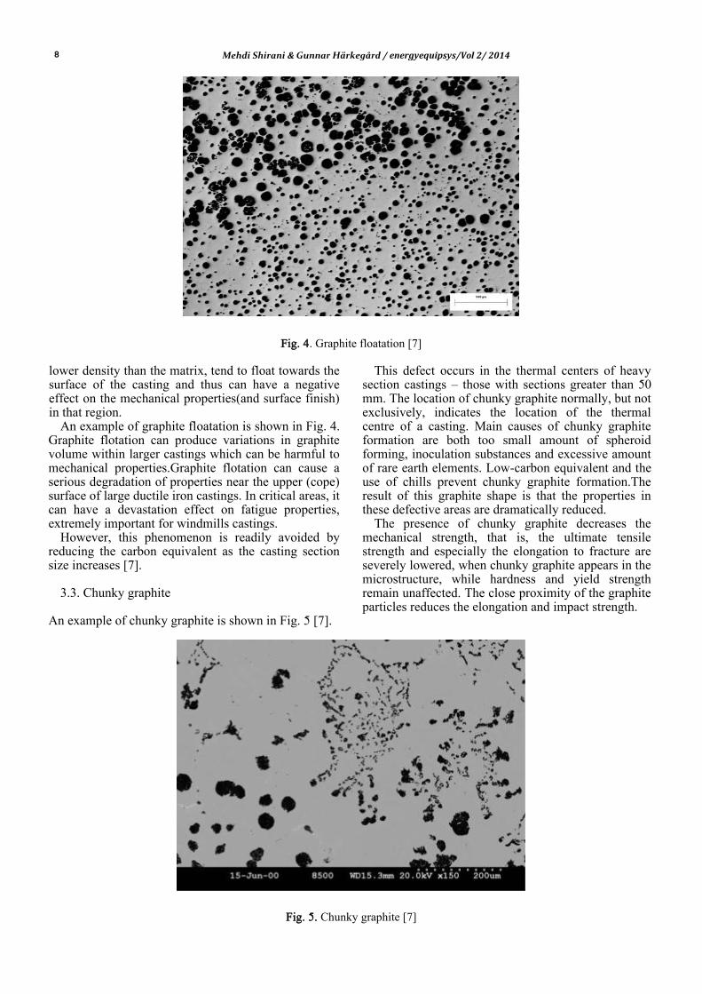
Fig. 4. Graphite floatation [7]
lower density than the matrix, tend to float towards the surface of the casting and thus can have a negative effect on the mechanical properties(and surface finish) in that region.
An example of graphite floatation is shown in Fig. 4. Graphite flotation can produce variations in graphite volume within larger castings which can be harmful to mechanical properties.Graphite flotation can cause a serious degradation of properties near the upper (cope) surface of large ductile iron castings. In critical areas, it can have a devastation effect on fatigue properties, extremely important for windmills castings.
However, this phenomenon is readily avoided by reducing the carbon equivalent as the casting section size increases [7].
3.3. Chunky graphite
An example of chunky graphite is shown in Fig. 5 [7].
This defect occurs in the thermal centers of heavy section castings – those with sections greater than 50 mm. The location of chunky graphite normally, but not exclusively, indicates the location of the thermal centre of a casting. Main causes of chunky graphite formation are both too small amount of spheroid forming, inoculation substances and excessive amount of rare earth elements. Low-carbon equivalent and the use of chills prevent chunky graphite formation.The result of this graphite shape is that the properties in these defective areas are dramatically reduced.
The presence of chunky graphite decreases the mechanical strength, that is, the ultimate tensile strength and especially the elongation to fracture are severely lowered, when chunky graphite appears in the microstructure, while hardness and yield strength remain unaffected. The close proximity of the graphite particles reduces the elongation and impact strength.
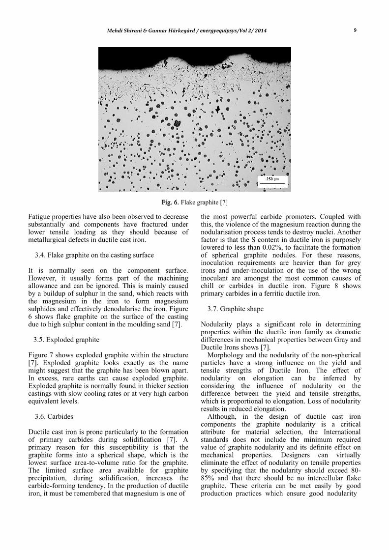
Fig. 5. Chunky graphite [7]
Mehdi Shirani & Gunnar Härkegård / energyequipsys/Vol 2/ 2014 9
Fig. 6. Flake graphite [7]
Fatigue properties have also been observed to decrease substantially and components have fractured under lower tensile loading as they should because of metallurgical defects in ductile cast iron.
3.4. Flake graphite on the casting surface
It is normally seen on the component surface. However, it usually forms part of the machining allowance and can be ignored. This is mainly caused by a buildup of sulphur in the sand, which reacts with the magnesium in the iron to form magnesium sulphides and effectively denodularise the iron. Figure 6 shows flake graphite on the surface of the casting due to high sulphur content in the moulding sand [7].
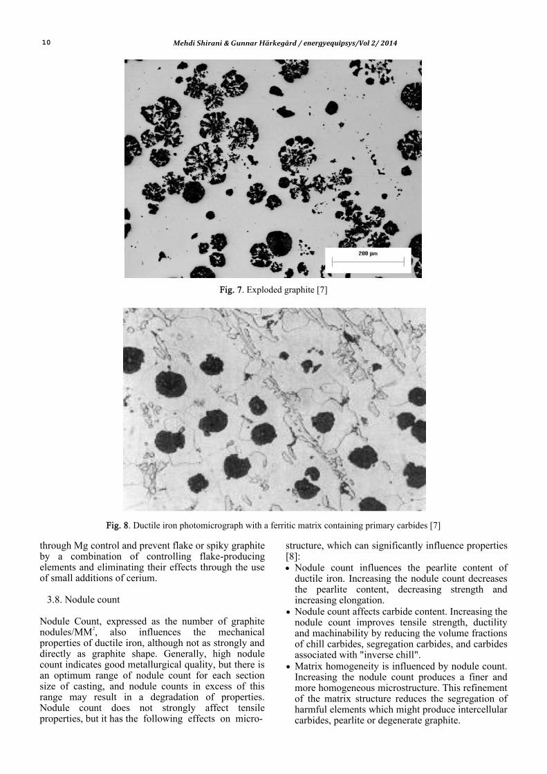
3.5. Exploded graphite
Figure 7 shows exploded graphite within the structure [7]. Exploded graphite looks exactly as the name might suggest that the graphite has been blown apart. In excess, rare earths can cause exploded graphite. Exploded graphite is normally found in thicker section castings with slow cooling rates or at very high carbon equivalent levels.
3.6. Carbides
Ductile cast iron is prone particularly to the formation of primary carbides during solidification [7]. A primary reason for this susceptibility is that the graphite forms into a spherical shape, which is the lowest surface area-to-volume ratio for the graphite. The limited surface area available for graphite precipitation, during solidification, increases the carbide-forming tendency. In the production of ductile iron, it must be remembered that magnesium is one of
the most powerful carbide promoters. Coupled with this, the violence of the magnesium reaction during the nodularisation process tends to destroy nuclei. Another factor is that the S content in ductile iron is purposely lowered to less than 0.02%, to facilitate the formation of spherical graphite nodules. For these reasons, inoculation requirements are heavier than for grey irons and under-inoculation or the use of the wrong inoculant are amongst the most common causes of chill or carbides in ductile iron. Figure 8 shows primary carbides in a ferritic ductile iron.
3.7. Graphite shape
Nodularity plays a significant role in determining properties within the ductile iron family as dramatic differences in mechanical properties between Gray and Ductile Irons shows [7].
Morphology and the nodularity of the non-spherical particles have a strong influence on the yield and tensile strengths of Ductile Iron. The effect of nodularity on elongation can be inferred by considering the influence of nodularity on the difference between the yield and tensile strengths, which is proportional to elongation. Loss of nodularity results in reduced elongation.
Although, in the design of ductile cast iron components the graphite nodularity is a critical attribute for material selection, the International standards does not include the minimum required value of graphite nodularity and its definite effect on mechanical properties. Designers can virtually eliminate the effect of nodularity on tensile properties by specifying that the nodularity should exceed 80-85% and that there should be no intercellular flake graphite. These criteria can be met easily by good production practices which ensure good nodularity
10 Mehdi Shirani & Gunnar Härkegård / energyequipsys/Vol 2/ 2014
Fig. 7. Exploded graphite [7]
Fig. 8. Ductile iron photomicrograph with a ferritic matrix containing primary carbides [7]
through Mg control and prevent flake or spiky graphite by a combination of controlling flake-producing elements and eliminating their effects through the use of small additions of cerium.
3.8. Nodule count
Nodule Count, expressed as the number of graphite nodules/MM2, also influences the mechanical properties of ductile iron, although not as strongly and directly as graphite shape. Generally, high nodule count indicates good metallurgical quality, but there is an optimum range of nodule count for each section size of casting, and nodule counts in excess of this range may result in a degradation of properties. Nodule count does not strongly affect tensile properties, but it has the following effects on micro-
structure, which can significantly influence properties [8]: Nodule count influences the pearlite content of
ductile iron. Increasing the nodule count decreases the pearlite content, decreasing strength and increasing elongation.
Nodule count affects carbide content. Increasing the nodule count improves tensile strength, ductility and machinability by reducing the volume fractions of chill carbides, segregation carbides, and carbides associated with "inverse chill".
Matrix homogeneity is influenced by nodule count. Increasing the nodule count produces a finer and more homogeneous microstructure. This refinement of the matrix structure reduces the segregation of harmful elements which might produce intercellular carbides, pearlite or degenerate graphite.
Mehdi Shirani & Gunnar Härkegård / energyequipsys/Vol 2/ 2014 11
Nodule count affects graphite size and shape. Increasing nodule count results in a decrease in nodule size which improves tensile, fatigue and fracture properties. Inoculation practices used to improve nodule count often make the nodules more spherical. Thus, high nodule count is generally associated with improved nodularity.
3.9. Graphite volume
The volume fraction of graphite in ductile iron can also influence certain tensile properties [8].
3.10. Matrix
In ductile irons with consistent nodularity and nodule count and low porosity and carbide content, mechanical properties are determined primarily by the matrix constituents and their hardness. For the most common grades of ductile iron, the matrix consists of ferrite and/or pearlite. Ferrite is the purest iron phase in ductile iron. It has low strength and hardness, but high ductility and toughness and good machinability. Pearlite is an intimate mixture of lamellar cementite in a matrix of ferrite. Compared to ferrite, pearlite provides a combination of higher strength and hardness and lower ductility. The mechanical properties of ferritic/ pearlitic ductile irons are, therefore, determined by the ratio of ferrite to pearlite in the matrix. This ratio is controlled in the as-cast condition by controlling the composition of the iron, taking into account the cooling rate of the casting. It can also be controlled by an annealing heat treatment to produce a fully ferritic casting, or by normalizing to maximize the pearlite content [8].
3.11. Shrinkage cavities
Many different causes can lead to shrinkage formation in ductile iron. Global experience has shown that about 50% of shrinkage defects are related to sand systems, feeding and gating. The other 50% may be attributed to metallurgical factors such as carbon equivalent, temperature, inoculation or high magnesium residuals [7, 8].
Casting section size can influence both the volume fraction and size of graphite nodules. Increased section size reduces the cooling rate of the casting, causing more carbon to precipitate in the stable graphite phase, instead of the carbide phase favoured by higher cooling rates. The lower cooling rates of the larger diameter bars also affect graphite nucleating conditions, resulting in reduced nodule count but increased nodule size. 4. Fatigue design of ductile cast iron components The current design of large wind turbine castings against fatigue is usually based on the safe life approach. In the safe life design, fatigue testing is
carried out on baseline material to produce S-N curves and these curves are used in fatigue design of the components. Since the physical phenomena behind these S-N curves are not known, to apply these curves to a real component, large reduction factors must be used to account for different parameters such as stress concentration, stress gradient, fatigue scatter and also taking into account nondestructive test results such as ultrasonic inspection or magnetic particle inspection.
As a result, in some situations, a significant portion of the useful life of the structure remains unused once it is retired and thus the structure is heavily over-designed and in some other situations, the fatigue design of the component is non-conservative and the component has premature fatigue failure. To counter these drawbacks, alternative design philosophies like damage tolerant design were developed.
Weight is always an issue when designing wind turbine structures. To optimize wind turbine heavy section cast iron components in order to meet their performance goals while minimizing weight, change from safe life design to damage tolerant design of these castings seems to be inevitable.
4.1. Effect of metallurgical defects on fatigue behavior of EN-GJS-400-18-LT
Fatigue strength design of the wind turbine cast components is a complex task. The special characteristics of cast components like cast quality, size effects, surface roughness and so on are to be considered. The cast quality is a generic term for the amount of faults like shrink holes, dross, chunky graphite and texture degradation. A lot of these factors do influence the fatigue strength of the cast components. Casting defects such as shrinkage cavities, gas pores, chunky graphite and also material micro structure such as graphite nodule count and nodularity and also pearlite content can alter the fatigue behavior of this material.
In fact, most of the fatigue data which are available on fatigue behavior of EN-GJS-400-18-LT, are for clean material.
Due to the lack of reliable information on the effect of metallurgical defects on fatigue behavior of this material, most wind turbine designers do not tolerate the presence of metallurgical defects on the component surface. Most wind turbine manufacturers have strict quality control regulations for their castings and in most cases metallurgical flaws should be removed from the final component surface and if not possible, the component should be rejected.
A review of common metallurgical defects in ductile cast iron was performed in this paper. There is no any systematic data available on the influence of most metallurgical defects on fatigue behaviour of EN-GJS-400-18-LT. Recently, some researches have been performed to study the influence of chunky graphite and also microstructure on fatigue behaviour of EN-GJS-400-18-LT.
12 Mehdi Shirani & Gunnar Härkegård / energyequipsys/Vol 2/ 2014
Although, chunky graphite is usually formed in the center of the casting, after machining the component and removal of the material, it shows itself on the machined surface. A brief review of the results is presented here.
4.1.1. Chunky graphite effect on fatigue behavior of EN-GJS-400-18-LT
Several researches [9-12] reported that the presence of chunky graphite noticeably decreases the mechanical properties of the castings, specially the ultimate tensile strength and the elongation to failure. Hardness and yield stress were found not been affected by chunky graphite. Only few works [11-12] can be found in the literature about the influence of chunky graphite on fatigue properties of heavy-section cast iron. MOURUJARVI et al. [11] performed fatigue tests on EG-GJS-800-5C pearlitic ductile cast iron with different amount of chunky graphite.
They found that when chunky graphite exists in the microstructure, it causes a low nodular count and nodularity rate near the chunky graphite areas, which decreases the fatigue strength. Furthermore, the crack was observed to easily grow through the interconnected chunky graphite. On the other hand, crack growth in samples with high nodular count and no chunky graphite in the microstructure took place around the graphite nodules, and thus when the nodular count is optimal the crack growth rate slows down. Finally, it was found that the decrease of fatigue life continued significantly until 20% chunky graphite content. After that, the fatigue life did not change. Ferro et al. [12] studied high cycle fatigue properties of EN- GJS-400 ductile cast iron containing chunky graphite. Constant amplitude axial tests were performed at room
containing chunky graphite. Constant amplitude axial tests were performed at room temperature under a temperature under a nominal load ratio R = 0. In order to evaluate the influence of chunky graphite morphology on fatigue life, fatigue tests were carried out also on a second set of specimens without this microstructural defect. All samples were taken from the core of a large casting component. Metallurgical analyses were performed on all the samples and some important microstructural parameters (nodule count and nodularity rating, among others) were measured and compared. It was found that a mean content of 40% of chunky graphite in the microstructure (with respect to total graphite content) does not influence significantly the fatigue strength properties of the analyzed cast iron.
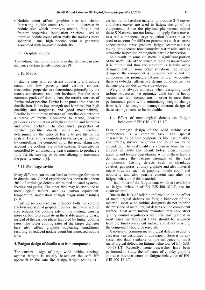
Tensile tests performed by Ferro et al. [12] on clean specimens and also specimens contain chunky graphite. Figure 9 shows a comparison between the nominal stress-strain curve of a chunky graphite-containing specimen and that of a chunky graphite-free sample. The mean percentage of chunky graphite found in the broken samples was 40%.As reported in the literature [11], the main difference in mechanical properties between the two groups of samples regards the mean elongation to fracture and the mean ultimate tensile strength; on the other hand, the mean yield stress is almost the same.
Fatigue tests performed by Ferro et al. [12] on clean specimens and also specimens contain chunky graphite. The obtained results were statistically elaborated by using a log-normal distribution. In addition to the mean curve relative to a survival probability of Ps = 50%, Figs. 10–12 show the scatter band defined by lines with 10 and 90% of survival probability.
Fig. 9. Comparison between the nominal stress-strain curve of a chunky graphite-containing specimen and that of a chunky graphite-free sample [12]
Mehdi Shirani & Gunnar Härkegård / energyequipsys/Vol 2/ 2014 13
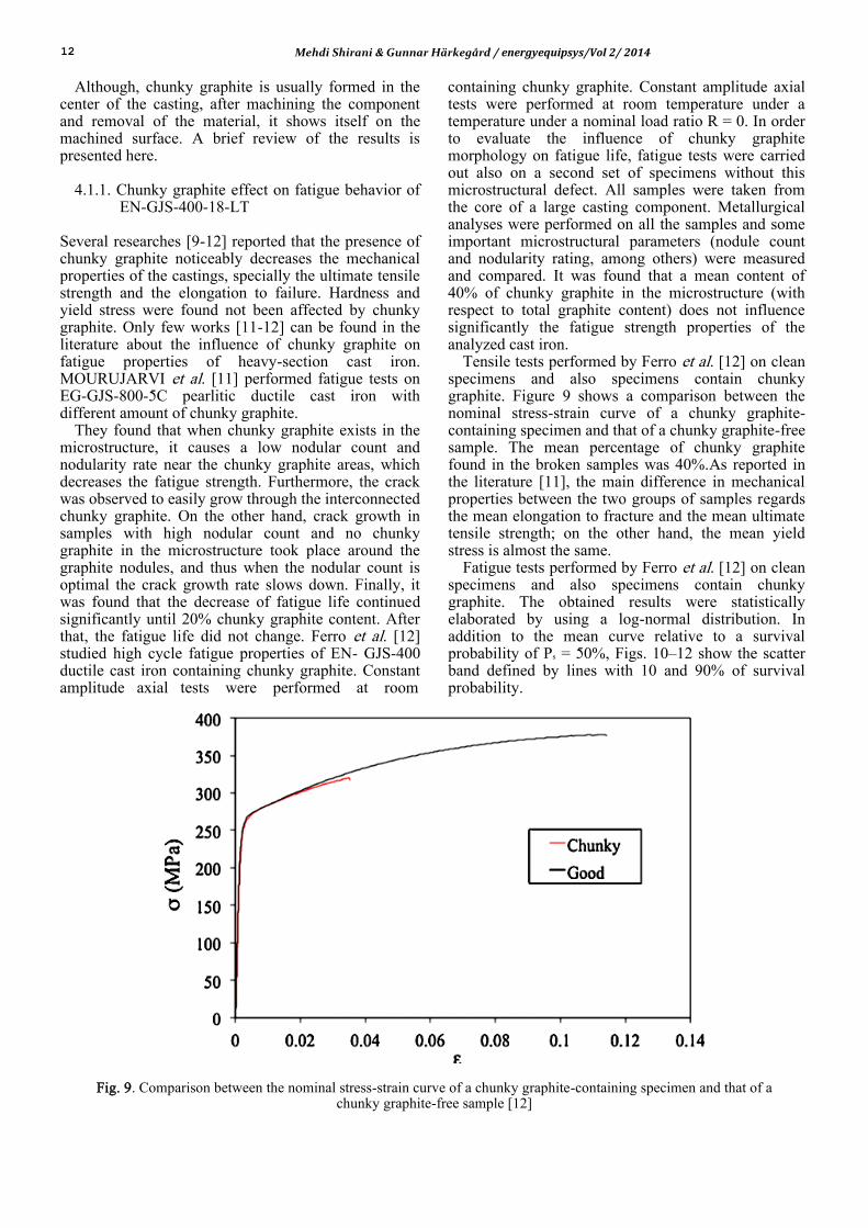
Figure 10 was obtained by elaborating only the
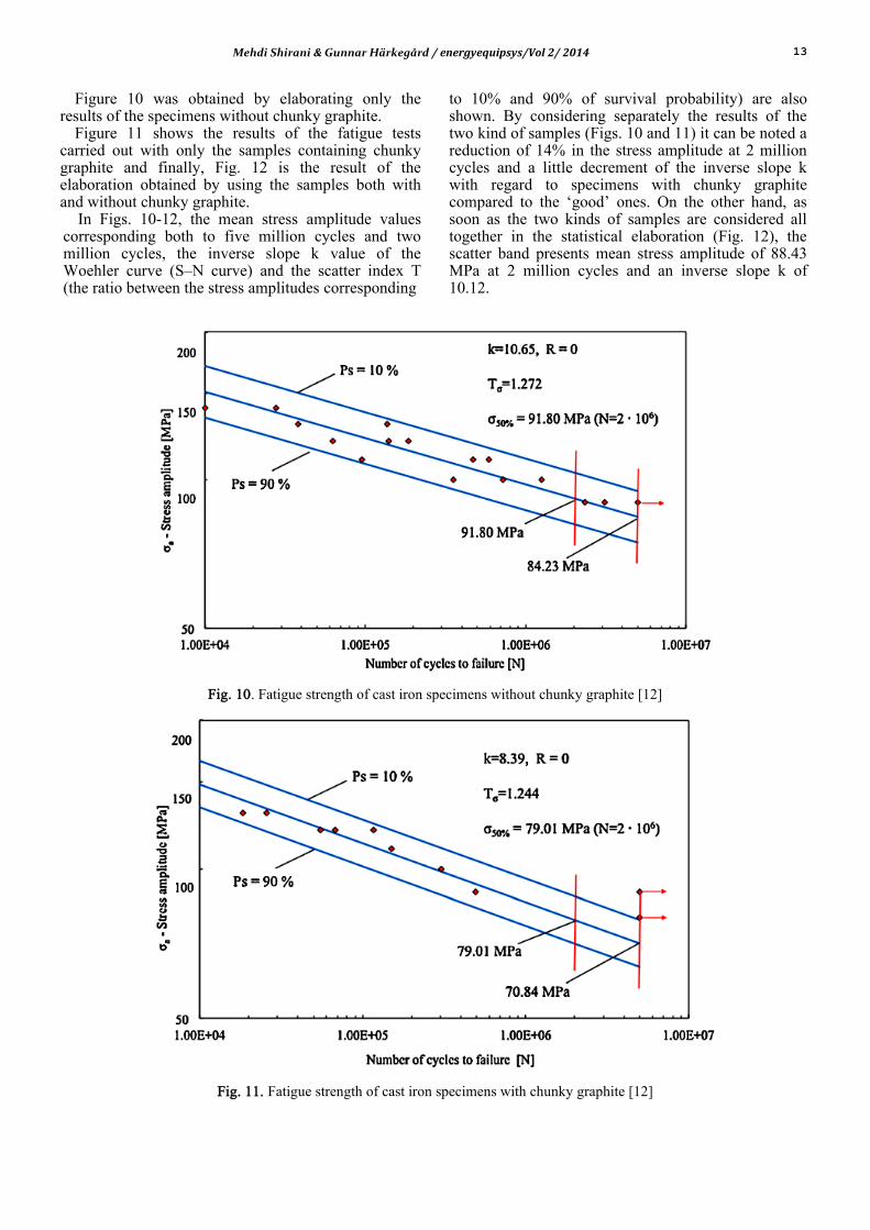
results of the specimens without chunky graphite. Figure 11 shows the results of the fatigue tests
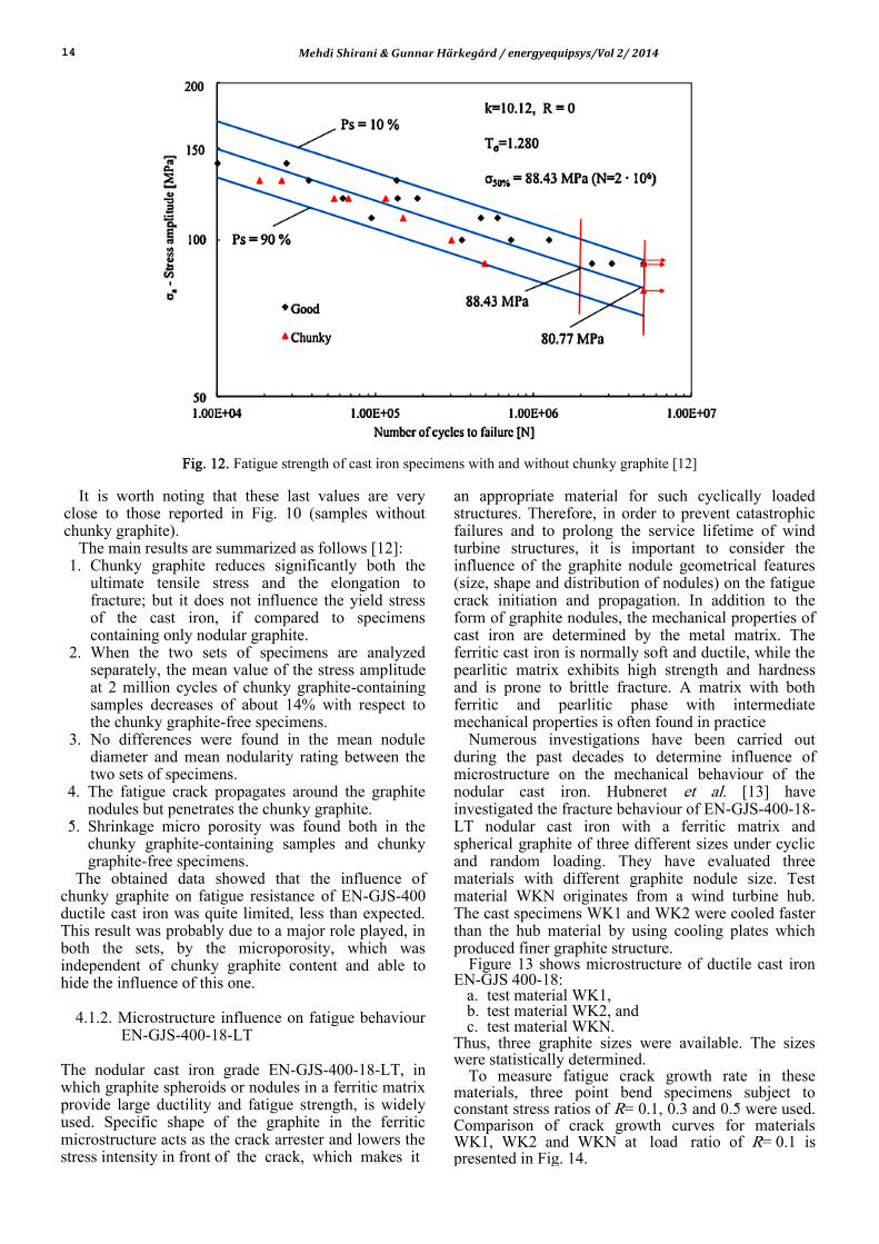
carried out with only the samples containing chunky graphite and finally, Fig. 12 is the result of the elaboration obtained by using the samples both with and without chunky graphite.
In Figs. 10-12, the mean stress amplitude values corresponding both to five million cycles and two million cycles, the inverse slope k value of the Woehler curve (S–N curve) and the scatter index T (the ratio between the stress amplitudes corresponding
to 10% and 90% of survival probability) are also shown. By considering separately the results of the two kind of samples (Figs. 10 and 11) it can be noted a reduction of 14% in the stress amplitude at 2 million cycles and a little decrement of the inverse slope k with regard to specimens with chunky graphite compared to the ‘good’ ones. On the other hand, as soon as the two kinds of samples are considered all together in the statistical elaboration (Fig. 12), the scatter band presents mean stress amplitude of 88.43 MPa at 2 million cycles and an inverse slope k of 10.12.
Fig. 10. Fatigue strength of cast iron specimens without chunky graphite [12]
Fig. 11. Fatigue strength of cast iron specimens with chunky graphite [12]
14 Mehdi Shirani & Gunnar Härkegård / energyequipsys/Vol 2/ 2014
Fig. 12. Fatigue strength of cast iron specimens with and without chunky graphite [12]
It is worth noting that these last values are very close to those reported in Fig. 10 (samples without chunky graphite).
The main results are summarized as follows [12]: 1. Chunky graphite reduces significantly both the
ultimate tensile stress and the elongation to fracture; but it does not influence the yield stress of the cast iron, if compared to specimens containing only nodular graphite.
2. When the two sets of specimens are analyzed separately, the mean value of the stress amplitude at 2 million cycles of chunky graphite-containing samples decreases of about 14% with respect to the chunky graphite-free specimens.
3. No differences were found in the mean nodule diameter and mean nodularity rating between the two sets of specimens.
4. The fatigue crack propagates around the graphite nodules but penetrates the chunky graphite.
5. Shrinkage micro porosity was found both in the chunky graphite-containing samples and chunky graphite-free specimens.
The obtained data showed that the influence of chunky graphite on fatigue resistance of EN-GJS-400 ductile cast iron was quite limited, less than expected. This result was probably due to a major role played, in both the sets, by the microporosity, which was independent of chunky graphite content and able to hide the influence of this one.
4.1.2. Microstructure influence on fatigue behaviour EN-GJS-400-18-LT
The nodular cast iron grade EN-GJS-400-18-LT, in which graphite spheroids or nodules in a ferritic matrix provide large ductility and fatigue strength, is widely used. Specific shape of the graphite in the ferritic microstructure acts as the crack arrester and lowers the stress intensity in front of the crack, which makes it
an appropriate material for such cyclically loaded structures. Therefore, in order to prevent catastrophic failures and to prolong the service lifetime of wind turbine structures, it is important to consider the influence of the graphite nodule geometrical features (size, shape and distribution of nodules) on the fatigue crack initiation and propagation. In addition to the form of graphite nodules, the mechanical properties of cast iron are determined by the metal matrix. The ferritic cast iron is normally soft and ductile, while the pearlitic matrix exhibits high strength and hardness and is prone to brittle fracture. A matrix with both ferritic and pearlitic phase with intermediate mechanical properties is often found in practice
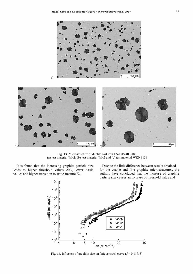
Numerous investigations have been carried out during the past decades to determine influence of microstructure on the mechanical behaviour of the nodular cast iron. Hubneret et al. [13] have investigated the fracture behaviour of EN-GJS-400-18-LT nodular cast iron with a ferritic matrix and spherical graphite of three different sizes under cyclic and random loading. They have evaluated three materials with different graphite nodule size. Test material WKN originates from a wind turbine hub. The cast specimens WK1 and WK2 were cooled faster than the hub material by using cooling plates which produced finer graphite structure.
Figure 13 shows microstructure of ductile cast iron EN-GJS 400-18:
a. test material WK1, b. test material WK2, and c. test material WKN.
Thus, three graphite sizes were available. The sizes were statistically determined.
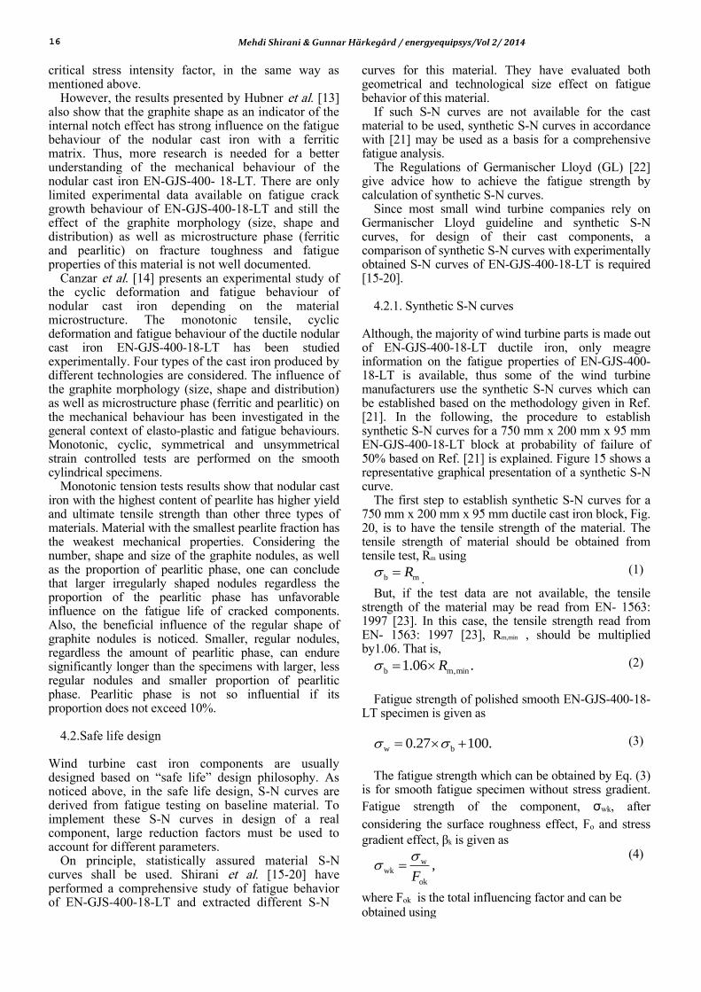
To measure fatigue crack growth rate in these materials, three point bend specimens subject to constant stress ratios of R= 0.1, 0.3 and 0.5 were used. Comparison of crack growth curves for materials WK1, WK2 and WKN at load ratio of R= 0.1 is presented in Fig. 14.
Mehdi Shirani & Gunnar Härkegård / energyequipsys/Vol 2/ 2014 15
a)
b) c)
Fig. 13. Microstructure of ductile cast iron EN-GJS 400-18:
(a) test material WK1, (b) test material WK2 and (c) test material WKN [13]
It is found that the increasing graphite particle size
leads to higher threshold values ΔKth, lower da/dn values and higher transition to static fracture Kc.
Despite the little difference between results obtained for the coarse and fine graphite microstructures, the authors have concluded that the increase of graphite particle size causes an increase of threshold value and
Fig. 14. Influence of graphite size on fatigue crack curve (R= 0.1) [13]
16 Mehdi Shirani & Gunnar Härkegård / energyequipsys/Vol 2/ 2014
critical stress intensity factor, in the same way as mentioned above.
However, the results presented by Hubner et al. [13] also show that the graphite shape as an indicator of the internal notch effect has strong influence on the fatigue behaviour of the nodular cast iron with a ferritic matrix. Thus, more research is needed for a better understanding of the mechanical behaviour of the nodular cast iron EN-GJS-400- 18-LT. There are only limited experimental data available on fatigue crack growth behaviour of EN-GJS-400-18-LT and still the effect of the graphite morphology (size, shape and distribution) as well as microstructure phase (ferritic and pearlitic) on fracture toughness and fatigue properties of this material is not well documented.
Canzar et al. [14] presents an experimental study of the cyclic deformation and fatigue behaviour of nodular cast iron depending on the material microstructure. The monotonic tensile, cyclic deformation and fatigue behaviour of the ductile nodular cast iron EN-GJS-400-18-LT has been studied experimentally. Four types of the cast iron produced by different technologies are considered. The influence of the graphite morphology (size, shape and distribution) as well as microstructure phase (ferritic and pearlitic) on the mechanical behaviour has been investigated in the general context of elasto-plastic and fatigue behaviours. Monotonic, cyclic, symmetrical and unsymmetrical strain controlled tests are performed on the smooth cylindrical specimens.
Monotonic tension tests results show that nodular cast iron with the highest content of pearlite has higher yield and ultimate tensile strength than other three types of materials. Material with the smallest pearlite fraction has the weakest mechanical properties. Considering the number, shape and size of the graphite nodules, as well as the proportion of pearlitic phase, one can conclude that larger irregularly shaped nodules regardless the proportion of the pearlitic phase has unfavorable influence on the fatigue life of cracked components. Also, the beneficial influence of the regular shape of graphite nodules is noticed. Smaller, regular nodules, regardless the amount of pearlitic phase, can endure significantly longer than the specimens with larger, less regular nodules and smaller proportion of pearlitic phase. Pearlitic phase is not so influential if its proportion does not exceed 10%.
4.2.Safe life design
Wind turbine cast iron components are usually designed based on ‚safe life‛ design philosophy. As noticed above, in the safe life design, S-N curves are derived from fatigue testing on baseline material. To implement these S-N curves in design of a real component, large reduction factors must be used to account for different parameters.
On principle, statistically assured material S-N curves shall be used. Shirani et al. [15-20] have performed a comprehensive study of fatigue behavior of EN-GJS-400-18-LT and extracted different S-N
curves for this material. They have evaluated both geometrical and technological size effect on fatigue behavior of this material.
If such S-N curves are not available for the cast material to be used, synthetic S-N curves in accordance with [21] may be used as a basis for a comprehensive fatigue analysis.
The Regulations of Germanischer Lloyd (GL) [22] give advice how to achieve the fatigue strength by calculation of synthetic S-N curves.
Since most small wind turbine companies rely on Germanischer Lloyd guideline and synthetic S-N curves, for design of their cast components, a comparison of synthetic S-N curves with experimentally obtained S-N curves of EN-GJS-400-18-LT is required [15-20].
4.2.1. Synthetic S-N curves
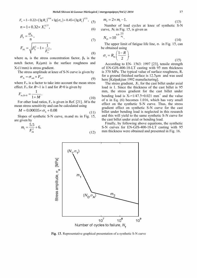
Although, the majority of wind turbine parts is made out of EN-GJS-400-18-LT ductile iron, only meagre information on the fatigue properties of EN-GJS-400-18-LT is available, thus some of the wind turbine manufacturers use the synthetic S-N curves which can be established based on the methodology given in Ref. [21]. In the following, the procedure to establish synthetic S-N curves for a 750 mm x 200 mm x 95 mm EN-GJS-400-18-LT block at probability of failure of 50% based on Ref. [21] is explained. Figure 15 shows a representative graphical presentation of a synthetic S-N curve.
The first step to establish synthetic S-N curves for a 750 mm x 200 mm x 95 mm ductile cast iron block, Fig. 20, is to have the tensile strength of the material. The tensile strength of material should be obtained from tensile test, Rm using
b mR .
(1)
But, if the test data are not available, the tensile strength of the material may be read from EN- 1563: 1997 [23]. In this case, the tensile strength read from EN- 1563: 1997 [23], Rm,min , should be multiplied by1.06. That is,
b m,min1.06 .R
(2)
Fatigue strength of polished smooth EN-GJS-400-18-
LT specimen is given as
w b0.27 100.
(3)
The fatigue strength which can be obtained by Eq. (3)
is for smooth fatigue specimen without stress gradient. Fatigue strength of the component, σwk, after
considering the surface roughness effect, Fo and stress gradient effect, βk is given as
wwk
ok
,F
(4)
where Fok is the total influencing factor and can be obtained using
Mehdi Shirani & Gunnar Härkegård / energyequipsys/Vol 2/ 2014 17
0.64 0.53
o z b z1 0.22 lg lg 0.45 lg ,F R R (5)
0.77
*1 0.32 ,n X (6)
kk ,
n
(7)
2
ok k 2
o
11 ,F
F
(8) where αk is the stress concentration factor, βk is the
notch factor, Rz(µm) is the surface roughness and
X*(1/mm) is stress gradient. The stress amplitude at knee of S-N curve is given by
A wk m ,F (9)
where Fm is a factor to take into account the mean stress effect. Fm for R=-1 is 1 and for R=0 is given by
m,R=0
1.
1F
M
(10) For other load ratios, Fm is given in Ref. [21]. M is the
mean stress sensitivity and can be calculated using
b0.00035 0.08M (11)
Slopes of synthetic S-N curve, m1and m2 in Fig. 15, are given by
1 2
ok
5.56.m
F
(12)
2 12 1.m m
(13) Number of load cycles at knee of synthetic S-N
curve, ND in Fig. 15, is given as
1
3.66.8
D 10 .m
N
(14)
The upper limit of fatigue life line, σ1 in Fig. 15, can be obtained using
1 m
1.
2
RR
(15) According to EN- 1563: 1997 [23], tensile strength
of EN-GJS-400-18-LT casting with 95 mm thickness is 370 MPa. The typical value of surface roughness, Rz
for a ground finished surface is 12.5µm and was used here [Kalpakjian 1992 manufacturing].
The stress gradient, X*, for the cast billet under axial load is 1. Since the thickness of the cast billet is 95 mm, the stress gradient for the cast billet under bending load is X*=1/47.5=0.021 mm
-1 and the value of n in Eq. (6) becomes 1.016, which has very small effect on the synthetic S-N curve. Thus, the stress gradient effect on synthetic S-N curve for the cast billet under bending load is neglected in this research and this will yield to the same synthetic S-N curve for the cast billet under axial or bending load.
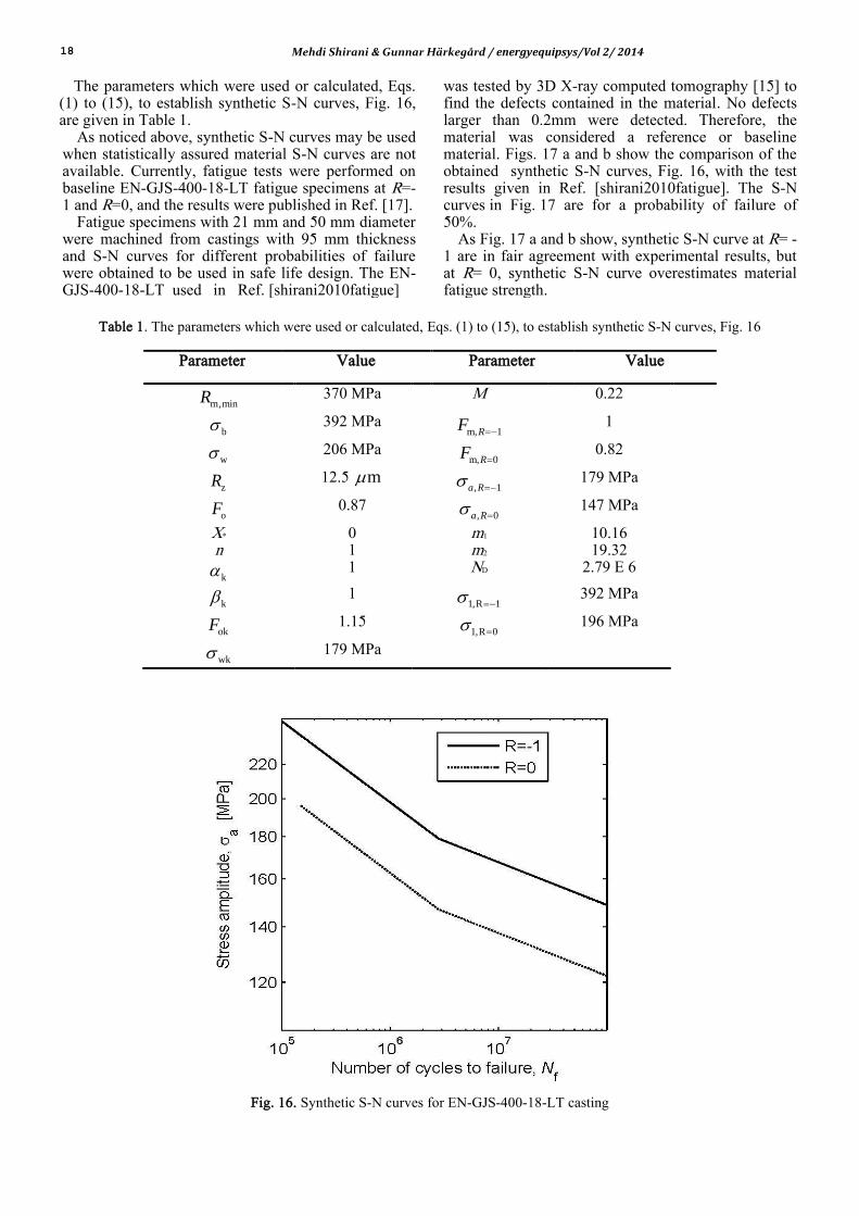
Finally, by following above equations, the synthetic S-N curves for EN-GJS-400-18-LT casting with 95 mm thickness were obtained and presented in Fig. 16.
Fig. 15. Representative graphical presentation of a synthetic S-N curve
18 Mehdi Shirani & Gunnar Härkegård / energyequipsys/Vol 2/ 2014
The parameters which were used or calculated, Eqs. (1) to (15), to establish synthetic S-N curves, Fig. 16, are given in Table 1.
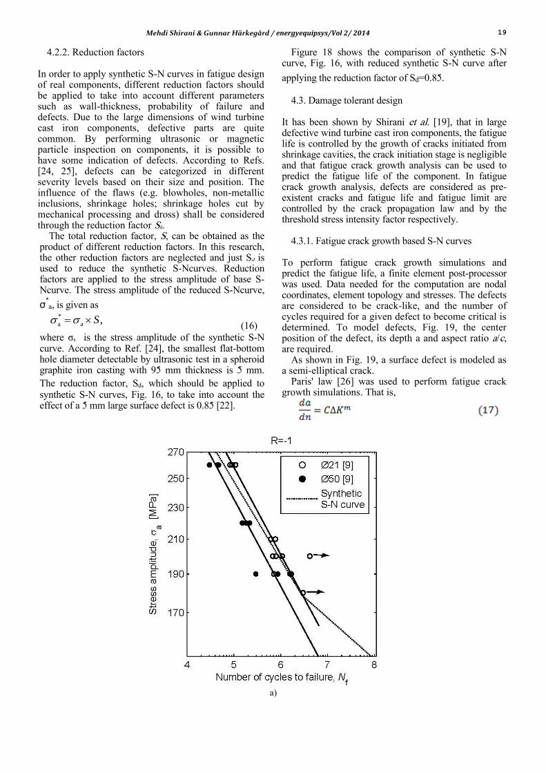
As noticed above, synthetic S-N curves may be used when statistically assured material S-N curves are not available. Currently, fatigue tests were performed on baseline EN-GJS-400-18-LT fatigue specimens at R=-1 and R=0, and the results were published in Ref. [17].
Fatigue specimens with 21 mm and 50 mm diameter were machined from castings with 95 mm thickness and S-N curves for different probabilities of failure were obtained to be used in safe life design. The EN-GJS-400-18-LT used in Ref. [shirani2010fatigue]
was tested by 3D X-ray computed tomography [15] to find the defects contained in the material. No defects larger than 0.2mm were detected. Therefore, the material was considered a reference or baseline material. Figs. 17 a and b show the comparison of the obtained synthetic S-N curves, Fig. 16, with the test results given in Ref. [shirani2010fatigue]. The S-N curves in Fig. 17 are for a probability of failure of 50%.
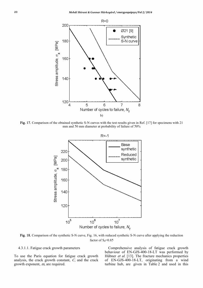
As Fig. 17 a and b show, synthetic S-N curve at R= -1 are in fair agreement with experimental results, but at R= 0, synthetic S-N curve overestimates material fatigue strength.
Table 1. The parameters which were used or calculated, Eqs. (1) to (15), to establish synthetic S-N curves, Fig. 16
Parameter Value Parameter Value
m,minR 370 MPa M 0.22
b 392 MPa m, 1RF 1
w 206 MPa m, 0RF 0.82
zR 12.5 m , 1a R 179 MPa
oF 0.87 , 0a R 147 MPa
X* 0 m1 10.16 n 1 m2 19.32
k 1 ND 2.79 E 6
k 1 1,R 1 392 MPa
okF 1.15 1,R 0 196 MPa
wk 179 MPa
Fig. 16. Synthetic S-N curves for EN-GJS-400-18-LT casting
Mehdi Shirani & Gunnar Härkegård / energyequipsys/Vol 2/ 2014 19
4.2.2. Reduction factors
In order to apply synthetic S-N curves in fatigue design of real components, different reduction factors should be applied to take into account different parameters such as wall-thickness, probability of failure and defects. Due to the large dimensions of wind turbine cast iron components, defective parts are quite common. By performing ultrasonic or magnetic particle inspection on components, it is possible to have some indication of defects. According to Refs. [24, 25], defects can be categorized in different severity levels based on their size and position. The influence of the flaws (e.g. blowholes, non-metallic inclusions, shrinkage holes; shrinkage holes cut by mechanical processing and dross) shall be considered through the reduction factor Sd.
The total reduction factor, S, can be obtained as the product of different reduction factors. In this research, the other reduction factors are neglected and just Sd is used to reduce the synthetic S-Ncurves. Reduction factors are applied to the stress amplitude of base S-Ncurve. The stress amplitude of the reduced S-Ncurve,
σ*a, is given as
*
a a ,S (16)
where σa is the stress amplitude of the synthetic S-N curve. According to Ref. [24], the smallest flat-bottom hole diameter detectable by ultrasonic test in a spheroid graphite iron casting with 95 mm thickness is 5 mm. The reduction factor, Sd, which should be applied to synthetic S-N curves, Fig. 16, to take into account the effect of a 5 mm large surface defect is 0.85 [22].
Figure 18 shows the comparison of synthetic S-N curve, Fig. 16, with reduced synthetic S-N curve after
applying the reduction factor of Sd=0.85.
4.3. Damage tolerant design
It has been shown by Shirani et al. [19], that in large defective wind turbine cast iron components, the fatigue life is controlled by the growth of cracks initiated from shrinkage cavities, the crack initiation stage is negligible and that fatigue crack growth analysis can be used to predict the fatigue life of the component. In fatigue crack growth analysis, defects are considered as pre-existent cracks and fatigue life and fatigue limit are controlled by the crack propagation law and by the threshold stress intensity factor respectively.
4.3.1. Fatigue crack growth based S-N curves
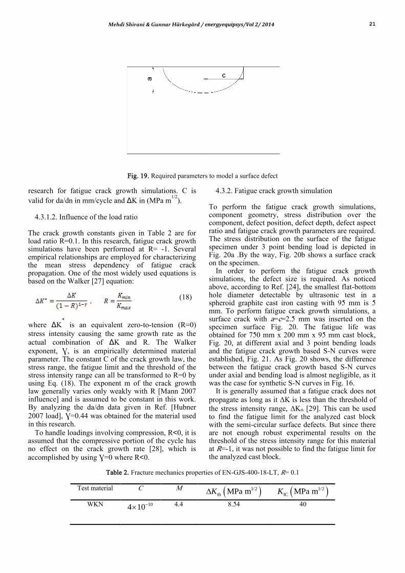
To perform fatigue crack growth simulations and predict the fatigue life, a finite element post-processor was used. Data needed for the computation are nodal coordinates, element topology and stresses. The defects are considered to be crack-like, and the number of cycles required for a given defect to become critical is determined. To model defects, Fig. 19, the center position of the defect, its depth a and aspect ratio a/c, are required.
As shown in Fig. 19, a surface defect is modeled as a semi-elliptical crack.
Paris' law [26] was used to perform fatigue crack growth simulations. That is,
a)
20 Mehdi Shirani & Gunnar Härkegård / energyequipsys/Vol 2/ 2014
b)
Fig. 17. Comparison of the obtained synthetic S-N curves with the test results given in Ref. [17] for specimens with 21 mm and 50 mm diameter at probability of failure of 50%
Fig. 18. Comparison of the synthetic S-N curve, Fig. 16, with reduced synthetic S-N curve after applying the reduction
factor of Sd=0.85
4.3.1.1. Fatigue crack growth parameters
To use the Paris equation for fatigue crack growth analysis, the crack growth constant, C, and the crack growth exponent, m, are required.
Comprehensive analysis of fatigue crack growth behaviour of EN-GJS-400-18-LT was performed by Hübner et al. [13]. The fracture mechanics properties of EN-GJS-400-18-LT, originating from a wind turbine hub, are given in Table 2 and used in this
Mehdi Shirani & Gunnar Härkegård / energyequipsys/Vol 2/ 2014 21
Fig. 19. Required parameters to model a surface defect
research for fatigue crack growth simulations. C is valid for da/dn in mm/cycle and ΔK in (MPa m
1/2).
4.3.1.2. Influence of the load ratio
The crack growth constants given in Table 2 are for load ratio R=0.1. In this research, fatigue crack growth simulations have been performed at R= -1. Several empirical relationships are employed for characterizing the mean stress dependency of fatigue crack propagation. One of the most widely used equations is based on the Walker [27] equation:
(18)
where ΔK* is an equivalent zero-to-tension (R=0)
stress intensity causing the same growth rate as the actual combination of ΔK and R. The Walker exponent, Ɣ, is an empirically determined material parameter. The constant C of the crack growth law, the stress range, the fatigue limit and the threshold of the stress intensity range can all be transformed to R=0 by using Eq. (18). The exponent m of the crack growth law generally varies only weakly with R [Mann 2007 influence] and is assumed to be constant in this work. By analyzing the da/dn data given in Ref. [Hubner 2007 load], Ɣ=0.44 was obtained for the material used in this research.
To handle loadings involving compression, R<0, it is assumed that the compressive portion of the cycle has no effect on the crack growth rate [28], which is accomplished by using Ɣ=0 where R<0.
4.3.2. Fatigue crack growth simulation
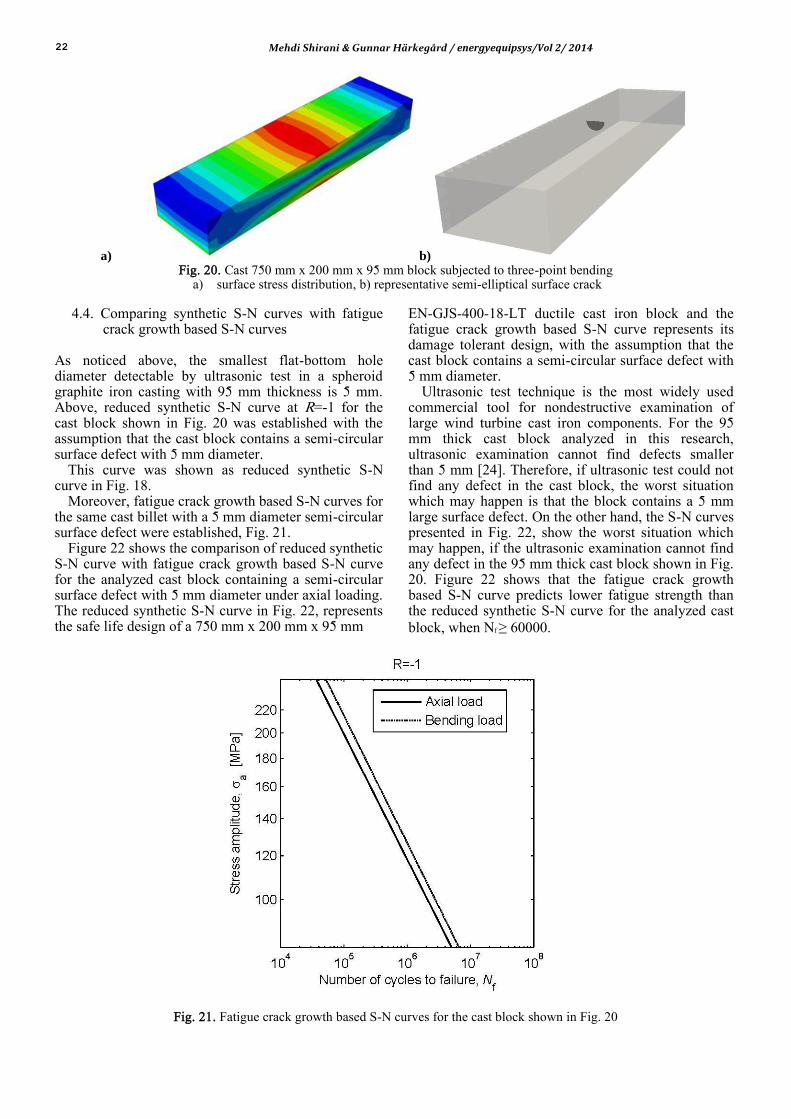
To perform the fatigue crack growth simulations, component geometry, stress distribution over the component, defect position, defect depth, defect aspect ratio and fatigue crack growth parameters are required. The stress distribution on the surface of the fatigue specimen under 3 point bending load is depicted in Fig. 20a .By the way, Fig. 20b shows a surface crack on the specimen.
In order to perform the fatigue crack growth simulations, the defect size is required. As noticed above, according to Ref. [24], the smallest flat-bottom hole diameter detectable by ultrasonic test in a spheroid graphite cast iron casting with 95 mm is 5 mm. To perform fatigue crack growth simulations, a surface crack with a=c=2.5 mm was inserted on the specimen surface Fig. 20. The fatigue life was obtained for 750 mm x 200 mm x 95 mm cast block, Fig. 20, at different axial and 3 point bending loads and the fatigue crack growth based S-N curves were established, Fig. 21. As Fig. 20 shows, the difference between the fatigue crack growth based S-N curves under axial and bending load is almost negligible, as it was the case for synthetic S-N curves in Fig. 16.
It is generally assumed that a fatigue crack does not propagate as long as it ΔK is less than the threshold of the stress intensity range, ΔKth [29]. This can be used to find the fatigue limit for the analyzed cast block with the semi-circular surface defects. But since there are not enough robust experimental results on the threshold of the stress intensity range for this material at R=-1, it was not possible to find the fatigue limit for the analyzed cast block.
Table 2. Fracture mechanics properties of EN-GJS-400-18-LT, R= 0.1
Test material C M 1/2
th MPa mK
1/2
IC MPa mK
WKN 104
10
4.4 8.54 40
22 Mehdi Shirani & Gunnar Härkegård / energyequipsys/Vol 2/ 2014
a) b) Fig. 20. Cast 750 mm x 200 mm x 95 mm block subjected to three-point bending
a) surface stress distribution, b) representative semi-elliptical surface crack
4.4. Comparing synthetic S-N curves with fatigue crack growth based S-N curves
As noticed above, the smallest flat-bottom hole diameter detectable by ultrasonic test in a spheroid graphite iron casting with 95 mm thickness is 5 mm. Above, reduced synthetic S-N curve at R=-1 for the cast block shown in Fig. 20 was established with the assumption that the cast block contains a semi-circular surface defect with 5 mm diameter.
This curve was shown as reduced synthetic S-N curve in Fig. 18.
Moreover, fatigue crack growth based S-N curves for the same cast billet with a 5 mm diameter semi-circular surface defect were established, Fig. 21.
Figure 22 shows the comparison of reduced synthetic S-N curve with fatigue crack growth based S-N curve for the analyzed cast block containing a semi-circular surface defect with 5 mm diameter under axial loading. The reduced synthetic S-N curve in Fig. 22, represents the safe life design of a 750 mm x 200 mm x 95 mm
EN-GJS-400-18-LT ductile cast iron block and the fatigue crack growth based S-N curve represents its damage tolerant design, with the assumption that the cast block contains a semi-circular surface defect with 5 mm diameter.
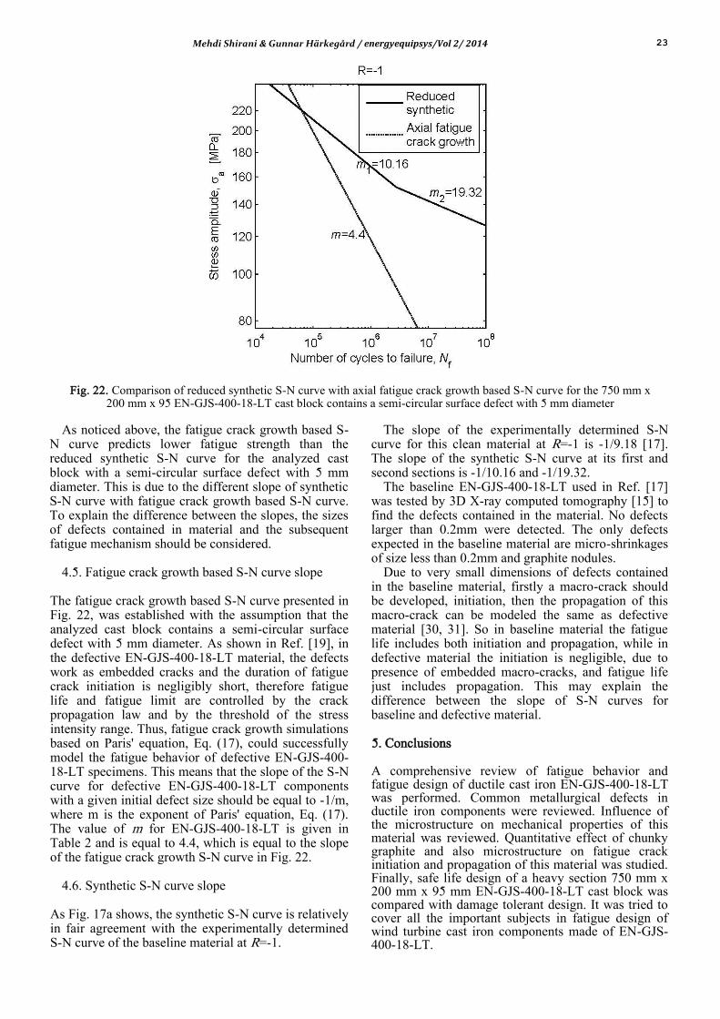
Ultrasonic test technique is the most widely used commercial tool for nondestructive examination of large wind turbine cast iron components. For the 95 mm thick cast block analyzed in this research, ultrasonic examination cannot find defects smaller than 5 mm [24]. Therefore, if ultrasonic test could not find any defect in the cast block, the worst situation which may happen is that the block contains a 5 mm large surface defect. On the other hand, the S-N curves presented in Fig. 22, show the worst situation which may happen, if the ultrasonic examination cannot find any defect in the 95 mm thick cast block shown in Fig. 20. Figure 22 shows that the fatigue crack growth based S-N curve predicts lower fatigue strength than the reduced synthetic S-N curve for the analyzed cast block, when Nf ≥ 60000.
Fig. 21. Fatigue crack growth based S-N curves for the cast block shown in Fig. 20
Mehdi Shirani & Gunnar Härkegård / energyequipsys/Vol 2/ 2014 23
Fig. 22. Comparison of reduced synthetic S-N curve with axial fatigue crack growth based S-N curve for the 750 mm x 200 mm x 95 EN-GJS-400-18-LT cast block contains a semi-circular surface defect with 5 mm diameter
As noticed above, the fatigue crack growth based S-
N curve predicts lower fatigue strength than the reduced synthetic S-N curve for the analyzed cast block with a semi-circular surface defect with 5 mm diameter. This is due to the different slope of synthetic S-N curve with fatigue crack growth based S-N curve. To explain the difference between the slopes, the sizes of defects contained in material and the subsequent fatigue mechanism should be considered.
4.5. Fatigue crack growth based S-N curve slope
The fatigue crack growth based S-N curve presented in Fig. 22, was established with the assumption that the analyzed cast block contains a semi-circular surface defect with 5 mm diameter. As shown in Ref. [19], in the defective EN-GJS-400-18-LT material, the defects work as embedded cracks and the duration of fatigue crack initiation is negligibly short, therefore fatigue life and fatigue limit are controlled by the crack propagation law and by the threshold of the stress intensity range. Thus, fatigue crack growth simulations based on Paris' equation, Eq. (17), could successfully model the fatigue behavior of defective EN-GJS-400-18-LT specimens. This means that the slope of the S-N curve for defective EN-GJS-400-18-LT components with a given initial defect size should be equal to -1/m, where m is the exponent of Paris' equation, Eq. (17). The value of m for EN-GJS-400-18-LT is given in Table 2 and is equal to 4.4, which is equal to the slope of the fatigue crack growth S-N curve in Fig. 22.
4.6. Synthetic S-N curve slope
As Fig. 17a shows, the synthetic S-N curve is relatively in fair agreement with the experimentally determined S-N curve of the baseline material at R=-1.
The slope of the experimentally determined S-N curve for this clean material at R=-1 is -1/9.18 [17]. The slope of the synthetic S-N curve at its first and second sections is -1/10.16 and -1/19.32.
The baseline EN-GJS-400-18-LT used in Ref. [17] was tested by 3D X-ray computed tomography [15] to find the defects contained in the material. No defects larger than 0.2mm were detected. The only defects expected in the baseline material are micro-shrinkages of size less than 0.2mm and graphite nodules.
Due to very small dimensions of defects contained in the baseline material, firstly a macro-crack should be developed, initiation, then the propagation of this macro-crack can be modeled the same as defective material [30, 31]. So in baseline material the fatigue life includes both initiation and propagation, while in defective material the initiation is negligible, due to presence of embedded macro-cracks, and fatigue life just includes propagation. This may explain the difference between the slope of S-N curves for baseline and defective material.
5. Conclusions
A comprehensive review of fatigue behavior and fatigue design of ductile cast iron EN-GJS-400-18-LT was performed. Common metallurgical defects in ductile iron components were reviewed. Influence of the microstructure on mechanical properties of this material was reviewed. Quantitative effect of chunky graphite and also microstructure on fatigue crack initiation and propagation of this material was studied. Finally, safe life design of a heavy section 750 mm x 200 mm x 95 mm EN-GJS-400-18-LT cast block was compared with damage tolerant design. It was tried to cover all the important subjects in fatigue design of wind turbine cast iron components made of EN-GJS-400-18-LT.
24 Mehdi Shirani & Gunnar Härkegård / energyequipsys/Vol 2/ 2014
References [1] Iulian Riposan, Mihai Chisamera, Stelian Stan,
Performance of heavy ductile iron castings for windmills, Overseas Foundry, Vol.7 No.2, 2010.
[2] http://en. wikipedia. org/wiki/Wind_power_by_ country.
[3] http://en.wikipedia.org/wiki/Ductile_iron. [4] DIN 1693, 1973, Cast Iron with Nodular Graphite;
Unalloyed and Low Alloy Grades. [5] Smith, William F.; Hashemi, Javad (2006),
Foundations of Materials Science and Engineering (4th ed.), McGraw-Hill, ISBN 0-07-295358-6.
[6] US patent 2485760, Keith Millis, "Cast Ferrous Alloy", issued 1949-10-25.
[7] Ecob C.M., 2005, A Review of Common Metallurgical Defects in Ductile Cast Iron, Customer Services Manager, Elkem AS, Foundry Products Division.
[8] Ductile iron data for design engineers, 1990, Rio Tinto Iron & Titanium, Inc., Montreal.
[9] Karsay S I and Campomanes E 1970 AFS Trans., 1970, vol. 78, pp. 85–92.
[10] R. Källbom, K. Hamberg, L.-E. Björkegren, in: J. Samuelson, G. Marquis, J. Solin (Eds.), Component Design by Castings—Improvements in a Nordic Project, VTT, Helsinki, Finland, 2005, pp. 63–86.
[11] A. MOURUJARVI, K. WIDELL, T. SAUKKONEN and H. HANNINEN, Influence of chunky graphite on mechanical and fatigue properties of heavy-section cast iron, Fatigue & Fracture of Engineering Materials & Structures, Volume 32, Issue 5, pages 379–390, May 2009.
[12] P. Ferro, P. Lazzarin,F. Berto, Fatigue properties of ductile cast iron containing chunky graphite, Materials Science and Engineering A 554 (2012) 122– 128.
[13] P. Hubner, H. Schlosser, G. Pusch, H. Biermann, Load history effects in ductile cast iron for wind turbine components, International Journal of Fatigue 29 (2007) 1788–1796.
[14] P. Canzar, Z.Tonkovic, J.Kodvanj, Microstructure influence on fatigue behavior of nodular cast iron, Materials Science & Engineering A556(2012) 88–99.
[15] M. Shirani, G. Härkegård,Fatigue Crack Growth Simulation in Components with Random Defects, Journal of ASTM International(ISSN 1546-962X), Volume 6, Issue 9, 2009.
[16] M. Shirani, G. Härkegård, N. Morin, Fatigue life prediction of components made of spheroidal graphite cast iron, Procedia Engineering Volume 2, Issue 1, April 2010, Pages 1125–1130.
[17] M. Shirani, G. Härkegård, Fatigue life distribution and size effect in ductile cast iron for wind turbine components, Engineering Failure Analysis Volume 18, Issue 1, January 2011, Pages 12–24.
[18] M. Shirani, G. Härkegård, Large scale axial
fatigue testing of ductile cast iron for heavy section wind turbine components, Engineering Failure 1496–1510.
[19] M. Shirani, G. Härkegård, Casting defects and fatigue behaviour of ductile cast iron for wind turbine components: A comprehensive study, Materialwissenschaft und Werkstofftechnik, Special Issue: Structural Durability, Volume 42, Issue 12, pages 1059–1074, December 2011.
[20] M. Shirani, G. Härkegård, Damage tolerant design of cast components based on defects detected by 3D X-ray computed tomography, International Journal of Fatigue Volume 41, August 2012, Pages 188–198.
[21] H. Gudehus, H. Zenner, Leitfaden für eine Betriebsfestigkeitsberechnung, 4th Edition, Verlag Stahleisen, Düsseldorf 1999.
[22] G. Lloyd, Guideline for the certification of wind turbines, Germanische Lloyd, Hamburg, Germany 2010.
[23] EN 1563:1997, European Standard, Founding - Spheroidal graphite cast irons, CEN, June 1997.
[24] EN 12680-3:2003, Founding - Ultrasonic examination, Part 3: Spheroidal graphite cast iron castings, CEN, August 2003.
[25] EN 1369:1997. Founding - Magnetic particle inspection, CEN, July 1997.
[26] P. Paris, F. Erdogan, A critical analysis of crack propagation laws, Journal of Basic Engineering 85 (4) (1963) 528–534.
[27] K. Walker, The effect of stress ratio during crack propagation and fatigue for 2024-T3 and 7075-T6 aluminum., in: Effects of environment and complex load history on fatigue life: a symposium presented at the Fall Meeting [of the] American Society for Testing and Materials, Atlanta, Ga., 29 September-4 October, 1968, ASTM International, 1970, p. 1.
[28] N. Dowling, Mechanical behavior of materials: engineering methods for deformation, fracture, and fatigue, Prentice Hall Upper Saddle River, NJ, 2007.
[29] Y. Murakami, Metal fatigue: effects of small defects and nonmetallic inclusions, Elsevier Science Ltd, 2002.
[30] T. Marrow, J. Buffiere, P. Withers, G. Johnson, D. Engelberg, High resolution X-ray tomography of short fatigue crack nucleation in austempered ductile cast iron, International Journal of Fatigue 26 (7) (2004) 717–725.
[31] C. Verdu, J. Adrien, J. Buffière, Three-dimensional shape of the early stages of fatigue cracks nucleated in nodular cast iron, Materials Science and Engineering: A 483 (2008) 402–405.


![[XLS]gujarat-education.gov.ingujarat-education.gov.in/higher/Images/pvuapproved.xls · Web viewBHAVNA GAJERA GJS 21477 JAGDISHCHANDRA PRAGJIBHAI GJS 21267 BAVANJIBHAI BHALODIA GJS](https://img.pdfslide.net/doc/110x75/5a9f44287f8b9a6c178c87ea/xlsgujarat-viewbhavna-gajera-gjs-21477-jagdishchandra-pragjibhai-gjs-21267-bavanjibhai.jpg)