Embed Size (px)
Citation preview
International Journal of Science and Research (IJSR) ISSN (Online): 2319-7064
Impact Factor (2012): 3.358
Volume 3 Issue 7, July 2014 www.ijsr.net
Licensed Under Creative Commons Attribution CC BY
A Review on Fault Diagnosis of Induction Motor using Artificial Neural Networks
Kanika Gupta1, Arunpreet Kaur2
1,2Department of Electrical Engineering, Baddi University, Himachal Pradesh, India
Abstract: Different alternatives to detect and diagnose faults in induction machines have been proposed and implemented in the last years. The technology of artificial neural networks has been successfully used to solve the motor incipient fault detection problem. The characteristics, obtained by this technique, distinguish them from the traditional ones, which, in most cases, need that the machine which is being analyzed is not working to do the diagnosis. This paper reviews an artificial neural network (ANN) based technique to identify rotor faults in a three-phase induction motor. The main types of faults considered are broken bar and dynamic eccentricity. At light load, it is difficult to distinguish between healthy and faulty rotors because the characteristic broken rotor bar fault frequencies are very close to the fundamental component and their amplitudes are small in comparison. As a result, detection of the fault and classification of the fault severity under light load is almost impossible. In order to overcome this problem, the detection of rotor faults in induction machines is done by analysing the starting current using a newly developed quantification technique based on artificial neural networks. Keywords: Fault Diagnosis and Identification, induction motor, artificial neural network, broken bars, rotor faults 1. Introduction Induction motors are most used types of motors industrial applications. The use of induction motors is widespread. Induction motors play an important role in manufacturing environments, therefore, this type of machine is mainly considered. They are generally used in petrochemical industries, chemical and domestic appliances industries. In critical application such nuclear plants, aerospace and military applications, induction motors are also often used. Reliability must be of high standard in these applications [1]. Induction motors are the mainstay for every industry. However like any other machine, they will eventually fail because of heavy duty cycles, poor working environment, installation and manufacturing factors, etc. With escalating demands for reliability and efficiency, the field of fault diagnosis in induction motors is gaining importance. If the faults are not prognosticated beforehand, it may result in large revenue losses as well as pose threat to reliability and safety of operation. However, many methods have been proposed for fault detection and diagnosis, but most of the methods require a good deal of expertise to apply them successfully. Simpler approaches are needed to enable even amateurish operators with nominal knowledge of the system to scan the fault condition and make reliable decisions. Although these motors are reliable and robust, stresses of various natures (thermal, electrical, mechanical or environment) can affect the life span of this one by involving the occurrence of stator and/or rotor faults [2]. The rotor faults may occur during production as small faults or may result from production faults or mechanical, environmental, electromagnetic or thermal pressure on the rotor when the motor runs. Even if these faults are small at first, the faults greaten because of these pressures in course of time. Especially transient events accelerate this growth. Failed motors negatively affect torque, current and speed of the motor [3]. A single broken or cracked rotor bar may cause its neighbours to fail dues to increased currents in adjacent bars and consequently increased thermal and
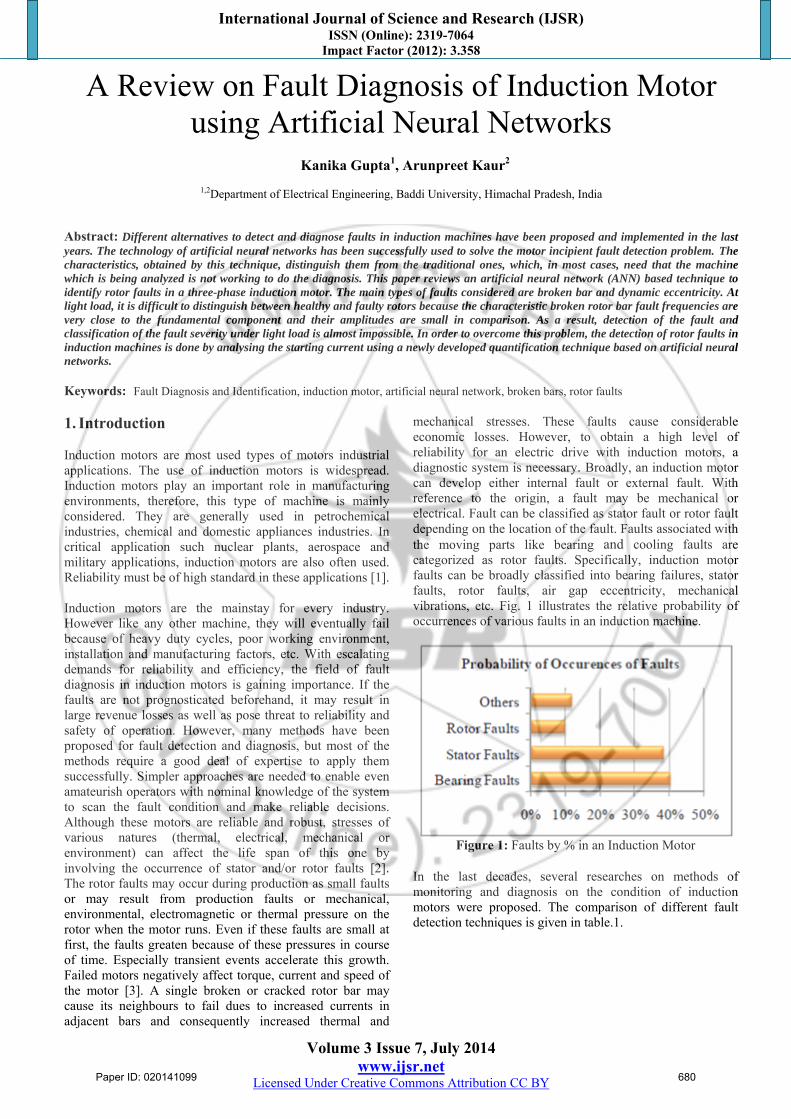
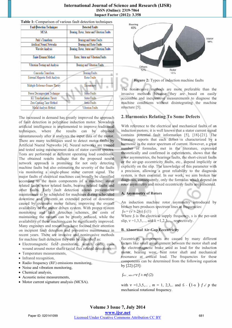
mechanical stresses. These faults cause considerable economic losses. However, to obtain a high level of reliability for an electric drive with induction motors, a diagnostic system is necessary. Broadly, an induction motor can develop either internal fault or external fault. With reference to the origin, a fault may be mechanical or electrical. Fault can be classified as stator fault or rotor fault depending on the location of the fault. Faults associated with the moving parts like bearing and cooling faults are categorized as rotor faults. Specifically, induction motor faults can be broadly classified into bearing failures, stator faults, rotor faults, air gap eccentricity, mechanical vibrations, etc. Fig. 1 illustrates the relative probability of occurrences of various faults in an induction machine.
Figure 1: Faults by % in an Induction Motor
In the last decades, several researches on methods of monitoring and diagnosis on the condition of induction motors were proposed. The comparison of different fault detection techniques is given in table.1.
Paper ID: 020141099 680
International Journal of Science and Research (IJSR) ISSN (Online): 2319-7064
Impact Factor (2012): 3.358
Volume 3 Issue 7, July 2014 www.ijsr.net
Licensed Under Creative Commons Attribution CC BY
Table 1: Comparison of various fault detection techniques
The increased in demand has greatly improved the approach of fault detection in polyphase induction motor. Nowadays artificial intelligence is implemented to improve traditional techniques, where the results can be obtained instantaneously after it analyzes the input data of the motor. There are many techniques used to detect motor faults by Artificial Nueral Networks [4]. Neural networks are trained and tested using measurement data of stator current spectra. Tests are performed at different operating load conditions. The obtained results indicate that the proposed neural network approach is promising for not only detecting machine faults but also estimating the severity of the faults via monitoring a single-phase stator current signal. The major faults of electrical machines can broadly be classified according to the main components of a machine: stator related faults, rotor related faults, bearing related faults and other faults. Early fault detection allows preventative maintenance to be scheduled for machines during scheduled downtime and prevents an extended period of downtime caused by extensive motor failure, improving the overall availability of the motor driven system. With proper system monitoring and fault detection schemes, the costs of maintaining the motors can be greatly reduced, while the availability of these machines can be significantly improved. Many engineers and researchers have focused their attention on incipient fault detection and preventive maintenance in recent years. There are invasive and noninvasive methods for machine fault detection they can be described as: Electromagnetic field monitoring, search coils, coils
wound around motor shafts (axial flux related detection), Temperature measurements, Infrared recognition, Radio frequency (RF) emissions monitoring, Noise and vibration monitoring, Chemical analysis, Acoustic noise measurements, Motor current signature analysis (MCSA).
Figure 2: Types of induction machine faults
The noninvasive methods are more preferable than the invasive methods because they are based on easily accessible and inexpensive measurements to diagnose the machine conditions without disintegrating the machine structure [5].
2. Harmonics Relating To Some Defects
With reference to the electrical and mechanical faults of an induction motors; it is well known that a stator current signal contains potential fault information [5], [18]-[21]. The literature reports that each defect is characterized by a harmonic in the stator spectrum of current. However, a great number of formulas, met in the literature, expressed theoretically and confirmed in experiments, shows that the rotor asymmetries, the bearings faults, the short-circuit faults or the air-gap eccentricity faults, etc., depend implicitly or explicitly on the slip. The knowledge of this parameter with a precision, allowing a great reliability to the diagnosis system, is then essential. In our work, we aim broken bar diagnosis, consequently, only the formulas which depend on rotor asymmetry and mixed eccentricity faults are presented. A. Asymmetry of Rotors An induction machine rotor asymmetry introduced by broken bars produces spectrum lines at frequencies: fbb = (ν ± 2ks) fs (1) Where fs is the electrical supply frequency, s is the per-unit slip, ν =1,3,5,..., and k =1,2,3,..., respectively. B. Abnormal Air-Gap Eccentricity Eccentricity components are caused by many different factors like small misalignment between the motor shaft and the electromagnetic brake used as load for the induction motor, bearing wear, bent rotor shaft and mechanical resonance at critical load. The frequencies for these components can be determined from the following equation by [22]-[25]: fecc _ mix s=ν f ± mf (2)
with ν =1,3,5,... , m = 1, 2,3,.. and fr = (1-s ) f s/ p the mechanical rotational frequency.
Paper ID: 020141099 681
International Journal of Science and Research (IJSR) ISSN (Online): 2319-7064
Impact Factor (2012): 3.358
Volume 3 Issue 7, July 2014 www.ijsr.net
Licensed Under Creative Commons Attribution CC BY
3. The Experimental Test Bench
The test bench (fig. 3) used in the experimental investigation is available at the LGEB in university of Biskra-Algeria (Fig.2). The experimental tests were carried out on three phase induction machines (1.1 kW, 50 Hz, 4 poles, 28 bars, Y connected). Only one stator was used for the tests with rotor interchangeability possibility: healthy, with one broken bar (1bb) and two broken bars (2bb). The acquisition is fixed to 10 seconds at the 10 kHz frequency through a D-Space 1104 board. For each type of rotor, 40 tests were carried out at different times and for three loads ranges: low, medium and full load. That is to say 120 tests for each rotor type of which 60 (20 for each load range) were used for the neural network training and the 60 remainders were left as test set for the neural network after training.
Figure 3: The experimental test bench
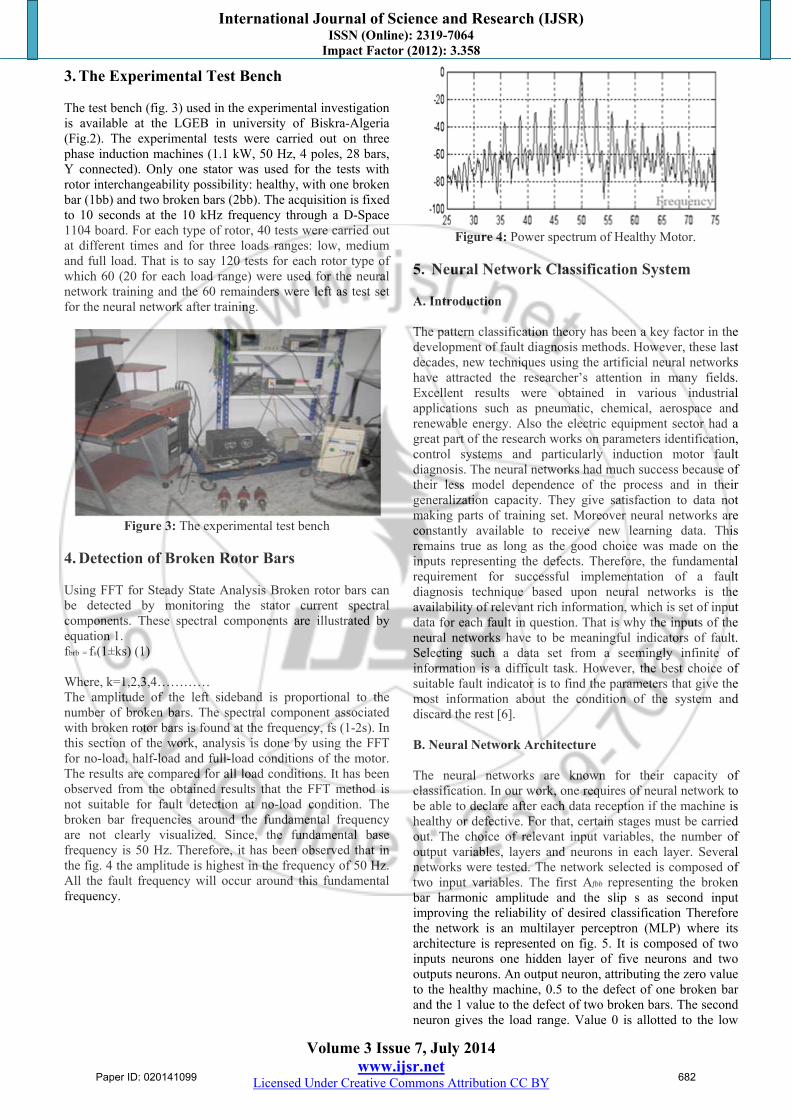
4. Detection of Broken Rotor Bars Using FFT for Steady State Analysis Broken rotor bars can be detected by monitoring the stator current spectral components. These spectral components are illustrated by equation 1. fbrb = fs(1±ks) (1) Where, k=1,2,3,4………… The amplitude of the left sideband is proportional to the number of broken bars. The spectral component associated with broken rotor bars is found at the frequency, fs (1-2s). In this section of the work, analysis is done by using the FFT for no-load, half-load and full-load conditions of the motor. The results are compared for all load conditions. It has been observed from the obtained results that the FFT method is not suitable for fault detection at no-load condition. The broken bar frequencies around the fundamental frequency are not clearly visualized. Since, the fundamental base frequency is 50 Hz. Therefore, it has been observed that in the fig. 4 the amplitude is highest in the frequency of 50 Hz. All the fault frequency will occur around this fundamental frequency.
Figure 4: Power spectrum of Healthy Motor.
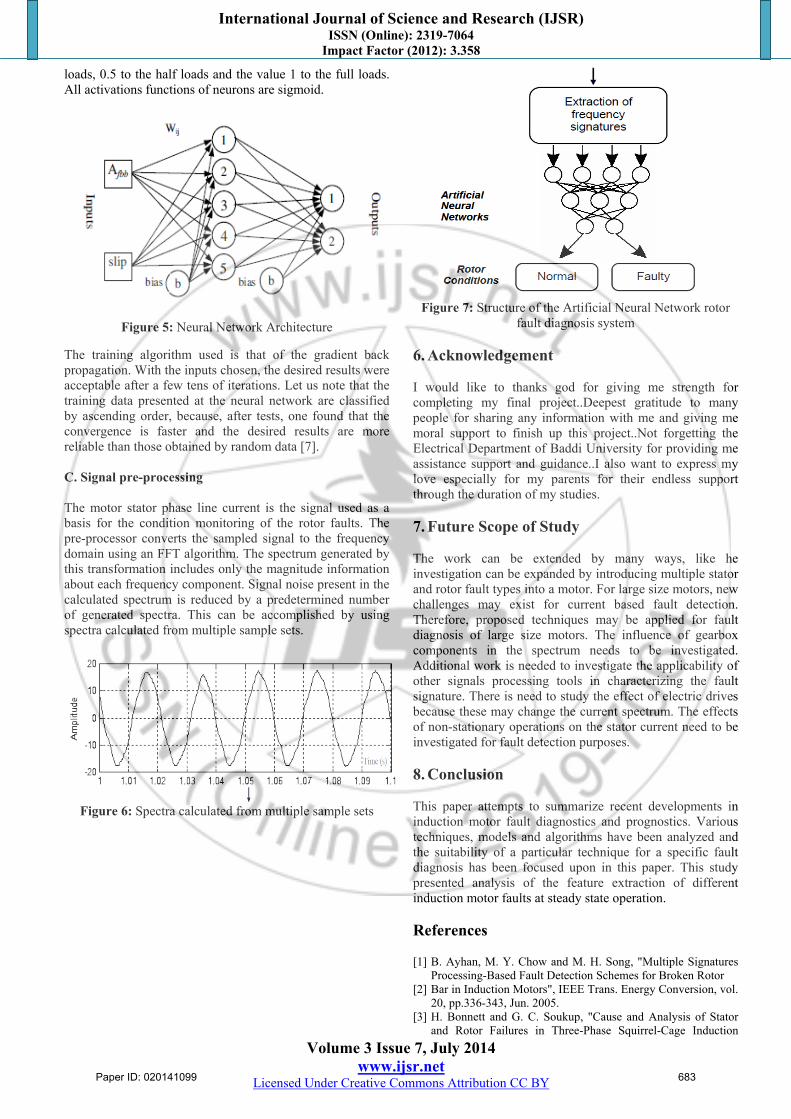
5. Neural Network Classification System A. Introduction The pattern classification theory has been a key factor in the development of fault diagnosis methods. However, these last decades, new techniques using the artificial neural networks have attracted the researcher’s attention in many fields. Excellent results were obtained in various industrial applications such as pneumatic, chemical, aerospace and renewable energy. Also the electric equipment sector had a great part of the research works on parameters identification, control systems and particularly induction motor fault diagnosis. The neural networks had much success because of their less model dependence of the process and in their generalization capacity. They give satisfaction to data not making parts of training set. Moreover neural networks are constantly available to receive new learning data. This remains true as long as the good choice was made on the inputs representing the defects. Therefore, the fundamental requirement for successful implementation of a fault diagnosis technique based upon neural networks is the availability of relevant rich information, which is set of input data for each fault in question. That is why the inputs of the neural networks have to be meaningful indicators of fault. Selecting such a data set from a seemingly infinite of information is a difficult task. However, the best choice of suitable fault indicator is to find the parameters that give the most information about the condition of the system and discard the rest [6]. B. Neural Network Architecture The neural networks are known for their capacity of classification. In our work, one requires of neural network to be able to declare after each data reception if the machine is healthy or defective. For that, certain stages must be carried out. The choice of relevant input variables, the number of output variables, layers and neurons in each layer. Several networks were tested. The network selected is composed of two input variables. The first Afbb representing the broken bar harmonic amplitude and the slip s as second input improving the reliability of desired classification Therefore the network is an multilayer perceptron (MLP) where its architecture is represented on fig. 5. It is composed of two inputs neurons one hidden layer of five neurons and two outputs neurons. An output neuron, attributing the zero value to the healthy machine, 0.5 to the defect of one broken bar and the 1 value to the defect of two broken bars. The second neuron gives the load range. Value 0 is allotted to the low
Paper ID: 020141099 682
International Journal of Science and Research (IJSR) ISSN (Online): 2319-7064
Impact Factor (2012): 3.358
Volume 3 Issue 7, July 2014 www.ijsr.net
Licensed Under Creative Commons Attribution CC BY
loads, 0.5 to the half loads and the value 1 to the full loads. All activations functions of neurons are sigmoid.
Figure 5: Neural Network Architecture
The training algorithm used is that of the gradient back propagation. With the inputs chosen, the desired results were acceptable after a few tens of iterations. Let us note that the training data presented at the neural network are classified by ascending order, because, after tests, one found that the convergence is faster and the desired results are more reliable than those obtained by random data [7]. C. Signal pre-processing The motor stator phase line current is the signal used as a basis for the condition monitoring of the rotor faults. The pre-processor converts the sampled signal to the frequency domain using an FFT algorithm. The spectrum generated by this transformation includes only the magnitude information about each frequency component. Signal noise present in the calculated spectrum is reduced by a predetermined number of generated spectra. This can be accomplished by using spectra calculated from multiple sample sets.
Figure 6: Spectra calculated from multiple sample sets
Figure 7: Structure of the Artificial Neural Network rotor
fault diagnosis system
6. Acknowledgement
I would like to thanks god for giving me strength for completing my final project..Deepest gratitude to many people for sharing any information with me and giving me moral support to finish up this project..Not forgetting the Electrical Department of Baddi University for providing me assistance support and guidance..I also want to express my love especially for my parents for their endless support through the duration of my studies. 7. Future Scope of Study The work can be extended by many ways, like he investigation can be expanded by introducing multiple stator and rotor fault types into a motor. For large size motors, new challenges may exist for current based fault detection. Therefore, proposed techniques may be applied for fault diagnosis of large size motors. The influence of gearbox components in the spectrum needs to be investigated. Additional work is needed to investigate the applicability of other signals processing tools in characterizing the fault signature. There is need to study the effect of electric drives because these may change the current spectrum. The effects of non-stationary operations on the stator current need to be investigated for fault detection purposes. 8. Conclusion
This paper attempts to summarize recent developments in induction motor fault diagnostics and prognostics. Various techniques, models and algorithms have been analyzed and the suitability of a particular technique for a specific fault diagnosis has been focused upon in this paper. This study presented analysis of the feature extraction of different induction motor faults at steady state operation.
References
[1] B. Ayhan, M. Y. Chow and M. H. Song, "Multiple Signatures
Processing-Based Fault Detection Schemes for Broken Rotor [2] Bar in Induction Motors", IEEE Trans. Energy Conversion, vol.
20, pp.336-343, Jun. 2005. [3] H. Bonnett and G. C. Soukup, "Cause and Analysis of Stator
and Rotor Failures in Three-Phase Squirrel-Cage Induction
Paper ID: 020141099 683
International Journal of Science and Research (IJSR) ISSN (Online): 2319-7064
Impact Factor (2012): 3.358
Volume 3 Issue 7, July 2014 www.ijsr.net
Licensed Under Creative Commons Attribution CC BY
Motors", IEEE Trans. Industry Applications, vol. 28, pp. 921- 937, Jul. /Aug. 1992.
[4] H. Arabaci and O. Bilgin, “Automatic Detection and Classification of Rotor Cage Faults in Squirrel Cage Induction Motor”, Neural Computing And Applications, Vol. 19, No. 5, pp. 713-723, Jan. 2010.
[5] Bellini, F. Filippetti, C. Tassoni, and G._A. Capolino, " Advances in Diagnostic Techniques for Induction Machines", IEEE Transactions on Industrial Electronics, vol. 55, n°12, Dec.2008, pp. 4109-4126.
[6] R. R. Schoen, B.K. Lin ,T. G. Habetler, J.H. Schlag and S.Farag, "An Unsupervised, On-Line System for Induction Motor Fault
[7] Detection Using Stator Current Monitoring," IEEE Transaction on Industry Applications, Vol.31, N°6, pp.1274-1279, November/December 1995.
[8] F. Filippetti, G. Franceschini, C. Tassoni, P. Vas, "Recent Developments of Induction Motor Drives Faults Diagnosis Using AI Techniques", IEEE Trans. Industrial Electronics, vol. 47, pp. 994 – 1004, Oct. 2000.
[9] William Torbat Thomson and Mark Fenger, "Industrial Application of Current Signature Analysis to diagnose Faults in 3-Phase Squirrel Cage Induction Motors", Pulp and Paper Industry Technical Conference, Conference Record of 2000 Annual, pp. 205-211, 19-23 June, 2000.
Author Profile
Kanika Gupta received the B-Tech degree in Electrical Engineering from Institute of Engineering and Emerging Technology in 2011. During 2007-2011, she worked in Electrical Machine Laboratory and various others laboratories of IEET preparing for
final project. Now she is pursuing M-Tech in Electrical Engineering from Baddi University of emerging sciences and technology. She is looking forward to work in this field only by this review article practically feasible for completing her masters.
Paper ID: 020141099 684


![Fault Diagnosis System of Induction Motors Based on Neural ...downloads.hindawi.com/journals/ijrm/2006/061690.pdf · Table 1: Fault occurrence possibility on induction motor [2]](https://img.pdfslide.net/doc/110x75/5ebcc7cd12e2c058e72a65f3/fault-diagnosis-system-of-induction-motors-based-on-neural-table-1-fault-occurrence.jpg)