Embed Size (px)
Citation preview
A review on microbial fuel cells (MFCs)
E. Bahrami, M. Gheisary, Gh. Bahrami
Abstract
Microbial fuel cell directly converts chemical energy to electrical energy through catalytic reactions using bacteria
and microbes. Due to decline of fossil fuels ,the necessity of replacing present energy source with an economical,
clean and renewable type has been felt completely. Microbial fuel cells are capable to use biomass, a renewable type
of energy source to generate electricity. They also have been applied specially in food processing industries for
wastewater treatment. MFC can work as biosensor for control of oxygen biological requirements. Additionally
Using MFC is a new method for generating hydrogen from organic matter metabolisms. This paper is a general
review of recent research advances in the configuration and performance of Microbial fuel cell which hopes to
highlight some important points regarding the recent advances.
Keywords: microbial fuel cell (MFC); Wastewater treatment; Electricity generation; Biosensor
1. Introduction
Nowadays due to the growing rate of increasing population and industrial improvements, energy
demanding drastically has gone up. It is obvious that Current reliance on fossil fuels is
unreasonable due to pollution and finite supplies. In this situation finding new, clean,
economical and sustainable sources of energy has become a big worldwide challenge.
At the present time much research is being done to find new energy solutions. Concerning high
rate of energy use, it appears that none of new energy sources will be able to replace fossil fuels
absolutely. Developments on MFC technology are very hopeful; this technology might be a real
solution for bringing to an end the energy crisis and global warming problem. Around one
hundred years ago for the first time M.C. potter presented the idea of using microbial fuel cell to
generate electricity [1].
A microbial fuel cell (MFC) is a system that drives a current by converting chemical energy to
electrical energy, using the microorganisms. An MFC consists of an anode, a cathode, and to
separate these it needs a membrane. In anode side there is some kinds of bacteria which degrade
organic materials. Released electrons move to cathode by an external circuit. Keeping balance
the system, protons as well go to cathodes trough a membrane. The result of this electron transfer
is an electrical current. As a matter of fact MFCs work the same as other types of fuel cells
other than they use some kinds of degradable chemicals as the fuel. MFCs could be classified to
two different types of Mediator and mediator-less Microbial Cells. Mediator Microbial Fuel Cells
are inactive which they need mediators for electron transferring. The mediator-less microbial fuel
cell does not require a mediator but uses some types of bacteria to transfer electrons to the
electrode [2].
One of the most common applications of MFCs rather than generating electricity is wastewater
treatment. Industrial, Sanitary and food processing wastewater which includes hydrocarbons can
be used as the fuel for MFCs Actually organic materials in waste water used by some kinds of
bacteria which exist in MFCs.
These systems are enough flexible regarding their kinds of fuel, have high efficiency and can
work for years without need to be charged again.
The importance of review articles to inform others about the latest achievements is undeniable.
Therefore this article hopes to briefly review the roles and importance of current microbial fuel
cells. However, it is unable to cover total field of MFC research but wishes to highlight some
important points regarding the recent advances.
2. History of microbial fuel cell development
At the end of recent century, the idea of using microbial cells was presented as a sustainable way
to generate electricity [14]. As a matter of fact M.C. Potter, Botanical Professor at the University
of Durham, was the first person who began study on microbial cell since 1911[14]. He intended
to generate electricity from E. coli. In 1931, Branet Cohen continued Potter’s work by employing
some semi microbial fuel cell in a series form which had only the production capacity of 35 volts
and two milliampere flows [15].Regarding thatmore activity was done by Del Duca et al. They
apply hydrogen which was produced from glucose fermentation using Clostridium butyricum as
the reactive material in fuel cell anode [16]. But it was not reliable enough due to the unstable
nature of microorganisms, in hydrogen production however this problem was solved by Suzuki et
al In 1976[17,18].Even after Suzuki's efforts, a few details of fuel cell performance was achieved
until complementary studies was done by the MJ Allen and H. Peter Benetto both from King
College London. As a matter of fact Bennetto was considered fuel cell as a method of generating
electricity for developing countries. He started his work in early 1980s, And his finding did a
remarkable help to understand how fuel cells work[19].
New discoveries indicate that electricity can be directly generated from organic material
decomposition in a fuel cell although the exact mechanism is not clarified in detail. In May
2007, at Queen Sland University in Australia, the MFC experimental samples be completed as a
joint project with the company Fosters Brewing. The experimental samples, with volume 10 L
fermentation plant wastewater into practice to carbon dioxide, clean water and electricity. In
Isfahan University of Technology Dr. Ali Akbar Dadkhah with using silver nanoparticles could
increase efficiency at Katvlyt microbial fuel cell with different concentrations. All the tests
conducted on two different electrodes with carbon cloth and carbon paper material, has
increased electric current can be up to 19 percent and power 29 percent compared to net Katvlyt
(without nanoparticles).
3. Overall view of Fuel cell
Fuel cell is a kind of electrochemical cell which directly converts chemical energy released from
the reaction to electrical energy .The main body of fuel cell consists of anode, cathode,
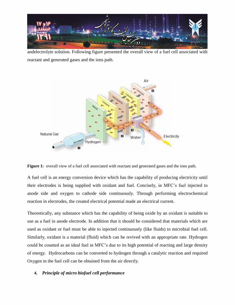
andelectrolyte solution. Following figure presented the overall view of a fuel cell associated with
reactant and generated gases and the ions path.
Figure 1: overall view of a fuel cell associated with reactant and generated gases and the ions path.
A fuel cell is an energy conversion device which has the capability of producing electricity until
their electrodes is being supplied with oxidant and fuel. Concisely, in MFC’s fuel injected to
anode side and oxygen to cathode side continuously. Through performing electrochemical
reaction in electrodes, the created electrical potential made an electrical current.
Theoretically, any substance which has the capability of being oxide by an oxidant is suitable to
use as a fuel in anode electrode. In addition that it should be considered that materials which are
used as oxidant or fuel must be able to injected continuously (like fluids) to microbial fuel cell.
Similarly, oxidant is a material (fluid) which can be revived with an appropriate rate. Hydrogen
could be counted as an ideal fuel in MFC’s due to its high potential of reacting and large density
of energy. Hydrocarbons can be converted to hydrogen through a catalytic reaction and required
Oxygen in the fuel cell can be obtained from the air directly.
4. Principle of micro biofuel cell performance
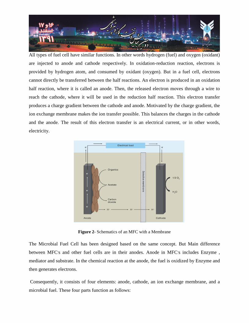
All types of fuel cell have similar functions. In other words hydrogen (fuel) and oxygen (oxidant)
are injected to anode and cathode respectively. In oxidation-reduction reaction, electrons is
provided by hydrogen atom, and consumed by oxidant (oxygen). But in a fuel cell, electrons
cannot directly be transferred between the half reactions. An electron is produced in an oxidation
half reaction, where it is called an anode. Then, the released electron moves through a wire to
reach the cathode, where it will be used in the reduction half reaction. This electron transfer
produces a charge gradient between the cathode and anode. Motivated by the charge gradient, the
ion exchange membrane makes the ion transfer possible. This balances the charges in the cathode
and the anode. The result of this electron transfer is an electrical current, or in other words,
electricity.
Figure 2- Schematics of an MFC with a Membrane
The Microbial Fuel Cell has been designed based on the same concept. But Main difference
between MFC,s and other fuel cells are in their anodes. Anode in MFC
,s includes Enzyme ,
mediator and substrate. In the chemical reaction at the anode, the fuel is oxidized by Enzyme and
then generates electrons.
Consequently, it consists of four elements: anode, cathode, an ion exchange membrane, and a
microbial fuel. These four parts function as follows:
4.1. Anodic chamber
The main purpose of anodic chamber is supplying fuel for the MFCs. through this chamber fuel
reach to anode side and catalytic layer, then consumed by an electrochemical reaction. Due to
prevent membrane from drying, water vapor are used to humid entering hydrogen.
4.2. Anode
Some bacteria work as anodes, and produce energy by oxidizing organics. Any oxidation
reaction requires an electron acceptor, which in this case could be an oxygen molecule, or any
other ions present in water that could be reduced. There are many different ways that bacteria can
carry their electrons from the oxidation site to the electron acceptor. Some bacteria use the
oxygen dissolved in water and reduce it inside their cells. A few others can actually transfer the
electrons outside their bodies and donate the electrons to the oxidizing agents. These bacteria can
grow in anaerobic environments, since they don't require oxygen. Oxygen is actually toxic and
deadly for some of them. In a fuel cell they will donate their electrons to the anode electrode and
these electrons will be used on the cathode side. This electron transfer is not only an energy
source for the bacterial culture, but it can also produce energy in an external resistance between
the anode and the cathode.
4.3. Cathodic chamber
Even if pure oxygen increases the efficiency of Fuel cell, we usually use air as an oxidant which
is more economical and safer. During a catalytic electrochemical reaction between protons and
oxygen, water becomes generated. Some water also moves toward the cathode through the
membrane. Accumulation of liquid water in cathode causes partial or total blockage of holes in
diffusion layer and prevents oxygen to reach to the catalyst sites.
4.4. Cathode
There are different types of cathodes, and there are different chemicals used in them. The most
economical cathode would use dissolved oxygen as the electron acceptor. Concentration of the
oxygen molecules is very low inside the water, so this kind of cathode will not produce a very
large driving force in comparison to other types of cathodes. On the other hand, this type of
cathode doesn’t need replacement, since the only element it consumes is oxygen, allowing it to
perform for a long period of time.
4.5. Ion Exchange Membrane
While the cell is performing and producing power, the charge of the cathode and anode becomes
unbalanced. Bacterial culture produces protons in the solution, so the anode becomes more positive.
Since the oxygen is reduced in the cathode, the cathode side becomes negative. In order to keep the
charge balance in cell there has to be an ion exchange membrane between the anode and the cathode.
The main difficulty is that this membrane can’t be exposed to air, because the anode side has to stay
anaerobic. This selective membrane only use protons move from anode side toward cathode.
5. The Microbial Fuel
Totally any compound that can be oxidized by microorganisms is suitable to use as fuel in MFCs.
research has shown that glucose and acetate are unusually good food sources for the microbe on the
anode. Glucose and acetate can be broken to sugars, carboxylic and alcohols which are consumed by
microorganisms on the anode, so waste water is a good choice to use as the food for MFCs. Hence
MFCs can be used in water treatment plant to reduce the organic contamination. In following table
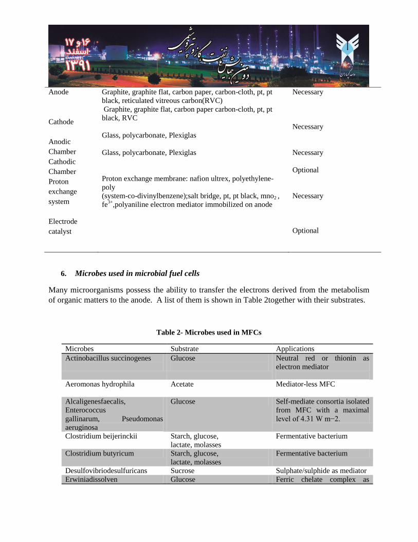
we introduce a summary of MFC components and material which are used to build MFCs.
Table 1- Basic components of microbial fuel cells
Items Material Remarks
Anode
Cathode
Anodic
Chamber
Cathodic
Chamber
Proton
exchange
system
Electrode
catalyst
Graphite, graphite flat, carbon paper, carbon-cloth, pt, pt
black, reticulated vitreous carbon(RVC)
Graphite, graphite flat, carbon paper carbon-cloth, pt, pt
black, RVC
Glass, polycarbonate, Plexiglas
Glass, polycarbonate, Plexiglas
Proton exchange membrane: nafion ultrex, polyethylene-
poly
(system-co-divinylbenzene);salt bridge, pt, pt black, mno2 ,
fe3+
,polyaniline electron mediator immobilized on anode
Necessary
Necessary
Necessary
Optional
Necessary
Optional
6. Microbes used in microbial fuel cells
Many microorganisms possess the ability to transfer the electrons derived from the metabolism
of organic matters to the anode. A list of them is shown in Table 2together with their substrates.
Table 2- Microbes used in MFCs
Applications Substrate Microbes
Neutral red or thionin as
electron mediator
Glucose
Actinobacillus succinogenes
Mediator-less MFC
Acetate
Aeromonas hydrophila
Self-mediate consortia isolated
from MFC with a maximal
level of 4.31 W m−2.
Glucose Alcaligenesfaecalis,
Enterococcus
gallinarum, Pseudomonas
aeruginosa
Fermentative bacterium Starch, glucose,
lactate, molasses
Clostridium beijerinckii
Fermentative bacterium Starch, glucose,
lactate, molasses
Clostridium butyricum
Sulphate/sulphide as mediator Sucrose Desulfovibriodesulfuricans
Ferric chelate complex as Glucose Erwiniadissolven
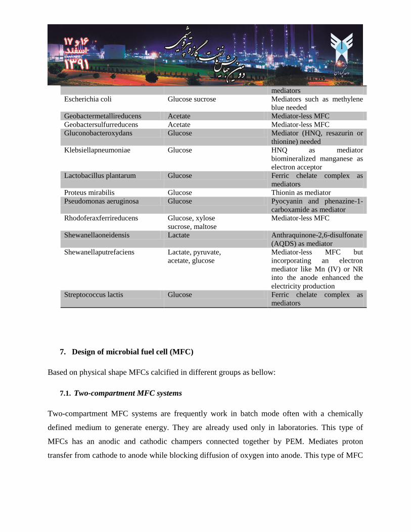
mediators
Mediators such as methylene
blue needed
Glucose sucrose Escherichia coli
Mediator-less MFC Acetate Geobactermetallireducens
Mediator-less MFC Acetate Geobactersulfurreducens
Mediator (HNQ, resazurin or
thionine) needed
Glucose Gluconobacteroxydans
HNQ as mediator
biomineralized manganese as
electron acceptor
Glucose Klebsiellapneumoniae
Ferric chelate complex as
mediators
Glucose Lactobacillus plantarum
Thionin as mediator Glucose Proteus mirabilis
Pyocyanin and phenazine-1-
carboxamide as mediator
Glucose Pseudomonas aeruginosa
Mediator-less MFC Glucose, xylose
sucrose, maltose
Rhodoferaxferrireducens
Anthraquinone-2,6-disulfonate
(AQDS) as mediator
Lactate Shewanellaoneidensis
Mediator-less MFC but
incorporating an electron
mediator like Mn (IV) or NR
into the anode enhanced the
electricity production
Lactate, pyruvate,
acetate, glucose
Shewanellaputrefaciens
Ferric chelate complex as
mediators
Glucose Streptococcus lactis
7. Design of microbial fuel cell (MFC)
Based on physical shape MFCs calcified in different groups as bellow:
7.1. Two-compartment MFC systems
Two-compartment MFC systems are frequently work in batch mode often with a chemically
defined medium to generate energy. They are already used only in laboratories. This type of
MFCs has an anodic and cathodic champers connected together by PEM. Mediates proton
transfer from cathode to anode while blocking diffusion of oxygen into anode. This type of MFC
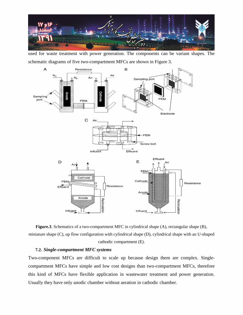
used for waste treatment with power generation. The components can be variant shapes. The
schematic diagrams of five two-compartment MFCs are shown in Figure 3.
Figure.3. Schematics of a two-compartment MFC in cylindrical shape (A), rectangular shape (B),
miniature shape (C), up flow configuration with cylindrical shape (D), cylindrical shape with an U-shaped
cathodic compartment (E).
7.2. Single-compartment MFC systems
Two-component MFCs are difficult to scale up because design them are complex. Single-
compartment MFCs have simple and low cost designs than two-compartment MFCs, therefore
this kind of MFCs have flexible application in wastewater treatment and power generation.
Usually they have only anodic chamber without aeration in cathodic chamber.
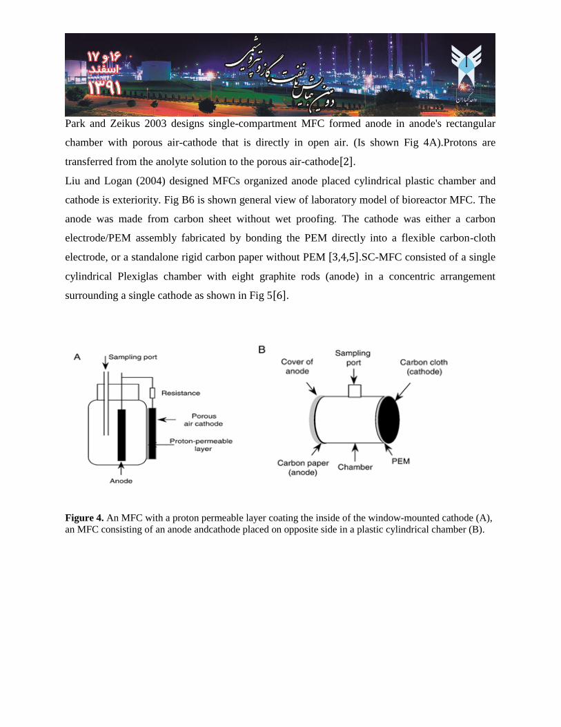
Park and Zeikus 2003 designs single-compartment MFC formed anode in anode's rectangular
chamber with porous air-cathode that is directly in open air. (Is shown Fig 4A).Protons are
transferred from the anolyte solution to the porous air-cathode[ ].
Liu and Logan (2004) designed MFCs organized anode placed cylindrical plastic chamber and
cathode is exteriority. Fig B6 is shown general view of laboratory model of bioreactor MFC. The
anode was made from carbon sheet without wet proofing. The cathode was either a carbon
electrode/PEM assembly fabricated by bonding the PEM directly into a flexible carbon-cloth
electrode, or a standalone rigid carbon paper without PEM [ ].SC-MFC consisted of a single
cylindrical Plexiglas chamber with eight graphite rods (anode) in a concentric arrangement
surrounding a single cathode as shown in Fig 5[ ].
Figure 4. An MFC with a proton permeable layer coating the inside of the window-mounted cathode (A),
an MFC consisting of an anode andcathode placed on opposite side in a plastic cylindrical chamber (B).
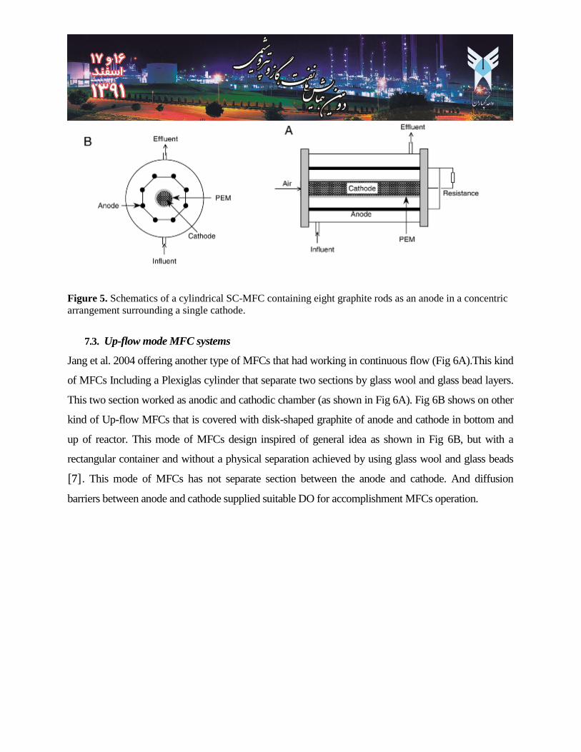
Figure 5. Schematics of a cylindrical SC-MFC containing eight graphite rods as an anode in a concentric
arrangement surrounding a single cathode.
7.3. Up-flow mode MFC systems
Jang et al. 2004 offering another type of MFCs that had working in continuous flow (Fig 6A).This kind
of MFCs Including a Plexiglas cylinder that separate two sections by glass wool and glass bead layers.
This two section worked as anodic and cathodic chamber (as shown in Fig 6A). Fig 6B shows on other
kind of Up-flow MFCs that is covered with disk-shaped graphite of anode and cathode in bottom and
up of reactor. This mode of MFCs design inspired of general idea as shown in Fig 6B, but with a
rectangular container and without a physical separation achieved by using glass wool and glass beads
[ ]. This mode of MFCs has not separate section between the anode and cathode. And diffusion
barriers between anode and cathode supplied suitable DO for accomplishment MFCs operation.
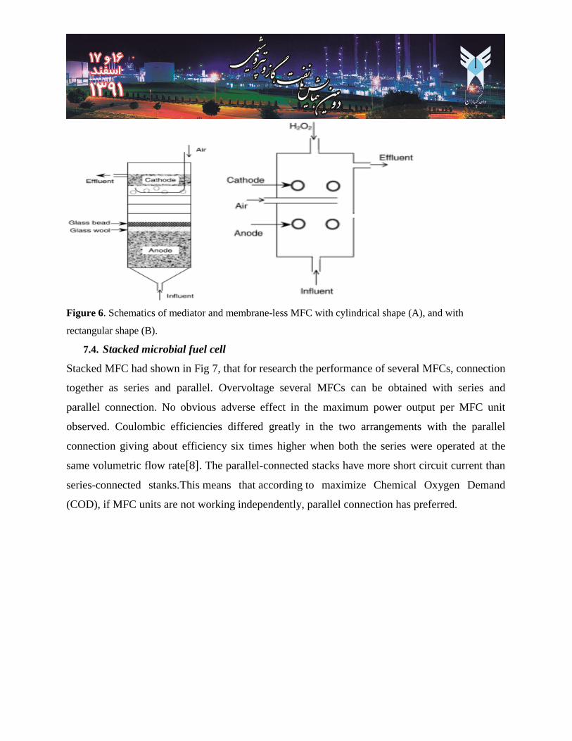
Figure 6. Schematics of mediator and membrane-less MFC with cylindrical shape (A), and with
rectangular shape (B).
7.4. Stacked microbial fuel cell
Stacked MFC had shown in Fig 7, that for research the performance of several MFCs, connection
together as series and parallel. Overvoltage several MFCs can be obtained with series and
parallel connection. No obvious adverse effect in the maximum power output per MFC unit
observed. Coulombic efficiencies differed greatly in the two arrangements with the parallel
connection giving about efficiency six times higher when both the series were operated at the
same volumetric flow rate[ ]. The parallel-connected stacks have more short circuit current than
series-connected stanks.This means that according to maximize Chemical Oxygen Demand
(COD), if MFC units are not working independently, parallel connection has preferred.
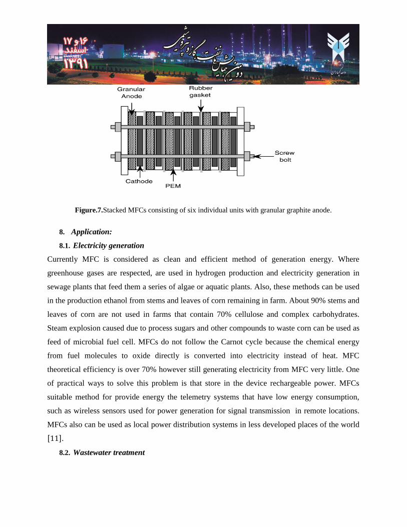
Figure.7.Stacked MFCs consisting of six individual units with granular graphite anode.
8. Application:
8.1. Electricity generation
Currently MFC is considered as clean and efficient method of generation energy. Where
greenhouse gases are respected, are used in hydrogen production and electricity generation in
sewage plants that feed them a series of algae or aquatic plants. Also, these methods can be used
in the production ethanol from stems and leaves of corn remaining in farm. About 90% stems and
leaves of corn are not used in farms that contain 70% cellulose and complex carbohydrates.
Steam explosion caused due to process sugars and other compounds to waste corn can be used as
feed of microbial fuel cell. MFCs do not follow the Carnot cycle because the chemical energy
from fuel molecules to oxide directly is converted into electricity instead of heat. MFC
theoretical efficiency is over 70% however still generating electricity from MFC very little. One
of practical ways to solve this problem is that store in the device rechargeable power. MFCs
suitable method for provide energy the telemetry systems that have low energy consumption,
such as wireless sensors used for power generation for signal transmission in remote locations.
MFCs also can be used as local power distribution systems in less developed places of the world
[ ].
8.2. Wastewater treatment
MFCs were applied onward of 1991 in the Wastewater Treatment. Urban wastewater contains
many organic compounds that can be used as fuel in MFCs. MFCs with specific microbes, have
special ability to remove sulfide in wastewater treatment. Sanitary waste, Swine waste water,
stem and leaves of corn are waste water treatment process feeds. MFCs are contain large coral
layers, therefore active microbes in their bio-electro-chemical in this two process reduce energy
demand, also reduce raw sewage by anaerobic organisms. MFCs series connection can be taken
better efficiency. And the remaining water in water treatment can be used in electricity system
generation [ ]
8.3. Biohydrogen
Usability of MFC is very much such as the new method of converting organic materials into
hydrogen fuel. This method is done by use of bacteria in a cell electrolysis microbe with acetic
acid in vinegar, where anode is graphite granules and cathode is carbon platinum catalyst.
Research teams from the University of Southern California have begun research to build fuel
cells (palm size) with the driving force powering the bacteria to set up with a miniature spy
planes (Insect size). But so far these demands failed due to lack of appropriate intensive energy
source [ ]
The team intends to determine transfer electrons in optimal conditions, to the anode surface in
different conditions. In low oxygen environments of bacteria to sewanell used the metal instead
oxygen for full metabolism food. That organism is able to convert electrons into the solid metal
oxides directly, that it can be used in fuel cell.
Sensor:
Biosensors device is converted biological response to an electrical signal. Biosensors are used to
identify specific molecules in Geology Applied Sciences potentially sensitive to recent events in
Laboratory systems [ ].
Such as:
1: sugar control in diabetic patients
2: detecting pesticides and water contaminants
3: Drug discovery and evaluation of new drug compounds, biological activity
An important part of applications biosensors in chemical reactor converters in order to:
1: Measure the heat generated (absorbed) by the reaction (biosensors calorimetric)
2: Measure the motion of electrons produced in the oxidation and reduction reaction (Ammete
biosensor)
3: Measure the effects of mass reactant or product (electrical biosensors)
9. References
1- Oh SE, Min B, Logan BE. Cathode performance as a factor in electricity generation in microbial fuel
cells. Environ Sci Technol2004; 38:4900–44.
2- Park DH, Zeikus JG. Improved fuel cell and electrode designs for producing electricity from microbial
degradation. Biotechnol Bioeng 2003; 81:348–55.
3- Liu H, Logan BE. Electricity generation using an air-cathode single chamber microbial fuel cell in the
presence and absence of a proton exchange membrane. Environ Sci Techno 2004; 38:4040–6.
4-Liu H, Cheng S, Logan BE. Production of electricity from acetate or butyrate using a single-chamber
microbial fuel cell. Environ Sci Technol 2005; 39:658–62.
5- And Cheng S, Liu H, Logan BE. Increased performance of single-chamber microbial fuel cells using an
improved cathode structure.ElectrochemCommun 2006; 8:489–94.
6- Liu H, Ramnarayanan R, Logan BE. Production of electricity during wastewater treatment using a
single chamber microbial fuel cell. Environ Sci Technol 2004; 28:2281–5.
7- Tartakovsky B Guiot SR. A comparison of air and hydrogen peroxide oxygenated microbial fuel cell
reactors. Biotechnol Prog 2006; 22:241–6.
8- Zhuwei Du, Haoran Li, Tingyue Gu. A state of the art review on microbial fuel cells: A promising
technology for wastewater treatment and bioenergy..
9- Deepak Pant , Gilbert Van Bogaert, Ludo Diels, Karolien Vanbroekhoven, A review of the substrates
used in microbial fuel cells (MFCs) for sustainable energy production
10- Deepak Pant, Gilbert Van Bogaert, Ludo Diels, Karolien Vanbroekhoven. A review of the substrates
used in microbial fuel cells (MFCs) for sustainable energy production
11- Guo-Wei Chen & Soo-Jung Choi & Tae-Ho Lee & Gil-Young Lee & Jae-Hwan Cha & Chang-Won
Kim Application ofbiocathodein microbial fuel cells: cell performance and microbial community.
12- Thomas K. Wood, Seiko Hoon Hong and Qun Ma.Engineering biofilm formation anddispersal.
13- Yu Lei a, Wilfred Chenb, Ashok MulchandaniReviewMicrobial biosensors.
14-Potter, M. C. (1911).Electrical effects accompanying the decomposition of organic compounds.Royal
Society (Formerly Proceedings of the Royal Society) B, 84:260-276.
15-Cohen, B. (1931).The bacterial culture as an electrical half-cell, Journal of Bacteriology, 21:18-19.
16-DelDuca, M. G., Friscoe, J. M. and Zurilla, R. W. (1963).Developments in industrial microbiology.
American Institute of Biological Sciences, 4:81-84.
17-Karube, I., Matasunga, T., Suzuki, S. and Tsuru, S. (1976) Continuous hydrogen production by
immobilized whole cells of Clostridium Butyricum. BiocheimicaetBiophysicaActa, 24:338-343.
18-Karube, I., Matasunga, T., Suzuki, S. and Tsuru, S. (1977). Biochemical cells utilizing immobilized
cells of Clostridium butyricum. Biotechnology and Bioengineering, 19:1727-1733.
19-Bennetto, H. P., Stirling, J. L., Tanaka, K. and Vega C. A. (1983).Anodic reaction in microbial fuel
cells. Biotechnology and Bioengineering, 25:559-568.