Embed Size (px)
Citation preview
This is a repository copy of A review on wear between railway wheels and rails under environmental conditions.
White Rose Research Online URL for this paper:http://eprints.whiterose.ac.uk/148889/
Version: Accepted Version
Article:
Zhu, Y., Wang, W.-J., Lewis, R. et al. (3 more authors) (2019) A review on wear between railway wheels and rails under environmental conditions. Journal of Tribology, 141 (12). 120801. ISSN 0742-4787
https://doi.org/10.1115/1.4044464
[email protected]://eprints.whiterose.ac.uk/
Reuse
This article is distributed under the terms of the Creative Commons Attribution (CC BY) licence. This licence allows you to distribute, remix, tweak, and build upon the work, even commercially, as long as you credit the authors for the original work. More information and the full terms of the licence here: https://creativecommons.org/licenses/
Takedown
If you consider content in White Rose Research Online to be in breach of UK law, please notify us by emailing [email protected] including the URL of the record and the reason for the withdrawal request.
American Society of
Mechanical Engineers
ASME Accepted Manuscript Repository
Institutional Repository Cover Sheet
Professor Roger Lewis
First Last
ASME Paper Title: A review on wear between railway wheels and rails under environmental conditions
Authors:
Zhu, Y., Wang, W.-J., Lewis, R., Yan, W., Lewis, S., Ding, H.
ASME Journal Title: Journal of Tribology
Volume/Issue _____141(12)__________________ Date of Publication (VOR* Online) _______05/09/2019
ASME Digital Collection URL:
https://asmedigitalcollection.asme.org/tribology/article/doi/10.1115/1.4044464/96075
Wear-Between-Railway-Wheels-and-Rails
DOI: 10.1115/1.4044464
*VOR (version of record)

1
A review on wear between railway wheels and rails under environmental conditions
Y. Zhua,b, W. Wangc, R. Lewisd, Wenyi Yane, S.R. Lewisf, H. Dingc
a. State key laboratory of fluid power and mechatronic systems, Zhejiang University, Zheda Road 38,
310027 Hangzhou, China
b. Ningbo Research Institute, Zhejiang University, 315100 Ningbo, China
c. Tribology research institute, Southwest Jiaotong University, No.111, First Section, North of Second
Ring Road, 610031 Chengdu, China
d. Department of Mechanical Engineering, the University of Sheffield, Mappin Street, Sheffield S1
3JD, UK
e. Department of Mechanical and Aerospace Engineering, Monash University, Clayton, Vic. 3800,
Australia
f. Rail Technologies, British Steel Ltd, Brigg Road, Scunthorpe, North Lincolnshire, DN16 1BP, UK.
Abstract:
The wheel-rail contact is an open system contact, which is subjected to various environmental
conditions, such as temperature, humidity, water, and even leaves. All these environmental factors
influence wheel-rail wear. Classical wheel-rail wear was basically discussed under dry and clean
conditions, particularly for engineering purposes. However, with the presence of environmental
conditions, wear rate and wear mechanism change. The paper reviews recent contributions to
wheel-rail wear with a special focus on the influence of environmental conditions. The main part
includes basics of wheel-rail wear, experimental methodology, wear and rolling contact fatigue (RCF),
and some measures to reduce wear.
Keywords: wheel-rail wear; environmental conditions; rolling contact fatigue; open system contact
1 Introduction
Railway transport is generally acknowledged for its low cost, energy efficiency, environmental
friendliness, ride comfort, and high speeds (over short and medium distances) compared with other
means of transportation. The wear between railway wheels and rails influences all of above mentioned
factors, particularly the cost of maintaining safe and efficient operations. Over time, the rail needs to be
ground and the wheels need to be turned to have a “matched” profile for improved running behavior
and safety. If the wear or fatigue is severe, the rail sections or the wheels may be replaced or discarded
before the expected lifetime. Around the year 2000, rail maintenance costs within the European Union
2
were estimated to total 300 million Euros annually [1]. In China, recent railway maintenance costs
were over 10 billion CNY annually, due to rapid expansion of the railway network.
Wheel-rail wear is a complex wear system. First, the contact point is constantly changing due to
vehicle dynamics. Second, the wheel-rail contact is a rolling/sliding contact. In addition to wear, rolling
contact fatigue (RCF) is also very important. Both aspects influence each other and are sometimes
coupled. Third, the wheel-rail contact system is an open system, which is affected by various
contaminants (foreign substances) applied both intentionally and unintentionally to the wheel–rail
interface [2,3]. These factors make the system different from other well-studied tribo-systems, such as
roller bearings, ball bearings or gears, which are often operated in a closed environment. Here,
environmental factors include temperature, humidity, iron oxides, leaves and water (rain) which differ
from those intentionally applied on the wheel-rail interface, such as lubricants and friction modifiers.
This paper reviews the research performed on the wear between the wheels and rails with a specific
focus on environmental factors. Section 2 presents basic information on wheel-rail wear including
contact conditions and classical wheel-rail wear behaviors. Section 3 discusses the methodology of
studying wheel-rail wear, which includes experimental methods. Sections 4 and 5 review the literature
on wear and RCF of the wheel-rail contact respectively. Section 6 presents measures that can be used to
reduce wear including lubricants and laser cladding. Finally, the concluding remarks summarize the
reviewed articles and identify gaps to be addressed in future work.
2 Basics of wheel-rail wear
It is often assumed that only a small area (1 cm2), where the wheel meets the rail, carries the axle load.
However, the contact position continuously varies, resulting in a varying contact area and contact
pressure due to different vehicle running conditions. There are different types of contacts, as shown in
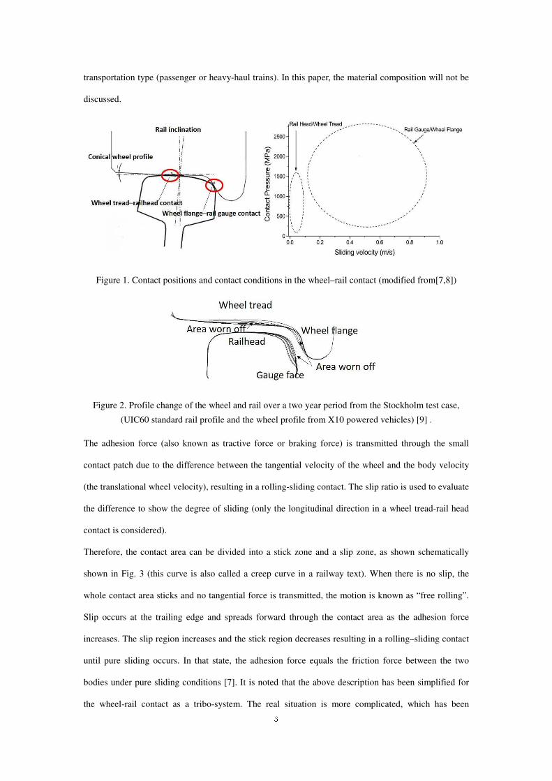
Fig. 1. The wheel tread-rail head contact usually occurs in a straight track where both contact pressure
and sliding speed are lower than they are for the wheel flange - rail gauge contact which often appears
in a curved track. Moreover, even for a single wheel, the profile changes due to wear lead to varied
contact pressure and contact area, as shown in Fig. 2. Notably, the real situation can be more complex
than mentioned here. Under such a high load, wheels and rails may deform plastically, particularly
when a rough surface is taken into account [4–6]. The wheel and rail materials used worldwide are
mostly carbon steels. The material composition may slightly differ depending on the country and the
3
transportation type (passenger or heavy-haul trains). In this paper, the material composition will not be
discussed.
Figure 1. Contact positions and contact conditions in the wheel–rail contact (modified from[7,8])
Figure 2. Profile change of the wheel and rail over a two year period from the Stockholm test case,
(UIC60 standard rail profile and the wheel profile from X10 powered vehicles) [9] .
The adhesion force (also known as tractive force or braking force) is transmitted through the small
contact patch due to the difference between the tangential velocity of the wheel and the body velocity
(the translational wheel velocity), resulting in a rolling-sliding contact. The slip ratio is used to evaluate
the difference to show the degree of sliding (only the longitudinal direction in a wheel tread-rail head
contact is considered).
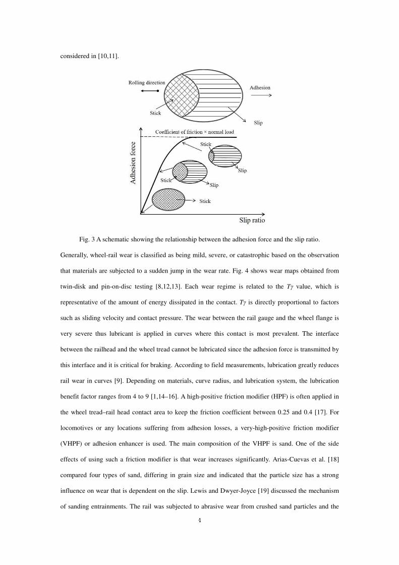
Therefore, the contact area can be divided into a stick zone and a slip zone, as shown schematically
shown in Fig. 3 (this curve is also called a creep curve in a railway text). When there is no slip, the
whole contact area sticks and no tangential force is transmitted, the motion is known as “free rolling”.
Slip occurs at the trailing edge and spreads forward through the contact area as the adhesion force
increases. The slip region increases and the stick region decreases resulting in a rolling–sliding contact
until pure sliding occurs. In that state, the adhesion force equals the friction force between the two
bodies under pure sliding conditions [7]. It is noted that the above description has been simplified for
the wheel-rail contact as a tribo-system. The real situation is more complicated, which has been
4
considered in [10,11].
Fig. 3 A schematic showing the relationship between the adhesion force and the slip ratio.
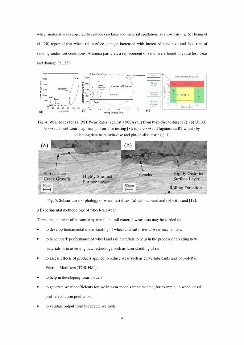
Generally, wheel-rail wear is classified as being mild, severe, or catastrophic based on the observation
that materials are subjected to a sudden jump in the wear rate. Fig. 4 shows wear maps obtained from
twin-disk and pin-on-disc testing [8,12,13]. Each wear regime is related to the Tγ value, which is
representative of the amount of energy dissipated in the contact. Tγ is directly proportional to factors
such as sliding velocity and contact pressure. The wear between the rail gauge and the wheel flange is
very severe thus lubricant is applied in curves where this contact is most prevalent. The interface
between the railhead and the wheel tread cannot be lubricated since the adhesion force is transmitted by
this interface and it is critical for braking. According to field measurements, lubrication greatly reduces
rail wear in curves [9]. Depending on materials, curve radius, and lubrication system, the lubrication
benefit factor ranges from 4 to 9 [1,14–16]. A high-positive friction modifier (HPF) is often applied in
the wheel tread–rail head contact area to keep the friction coefficient between 0.25 and 0.4 [17]. For
locomotives or any locations suffering from adhesion losses, a very-high-positive friction modifier
(VHPF) or adhesion enhancer is used. The main composition of the VHPF is sand. One of the side
effects of using such a friction modifier is that wear increases significantly. Arias-Cuevas et al. [18]
compared four types of sand, differing in grain size and indicated that the particle size has a strong
influence on wear that is dependent on the slip. Lewis and Dwyer-Joyce [19] discussed the mechanism
of sanding entrainments. The rail was subjected to abrasive wear from crushed sand particles and the
5
wheel material was subjected to surface cracking and material spallation, as shown in Fig. 5. Huang et
al. [20] reported that wheel-rail surface damage increased with increased sand size and feed rate of
sanding under wet conditions. Alumina particles, a replacement of sand, were found to cause less wear
and damage [21,22].
Fig. 4. Wear Maps for (a) R8T Wear Rates (against a 900A rail) from twin-disc testing [12]; (b) UIC60
900A rail steel wear map from pin-on-disc testing [8]; (c) a 900A rail (against an R7 wheel) by
collecting data from twin-disc and pin-on-disc testing [13].
Fig. 5. Subsurface morphology of wheel test discs: (a) without sand and (b) with sand [19].
3 Experimental methodology of wheel-rail wear
There are a number of reasons why wheel and rail material wear tests may be carried out:
• to develop fundamental understanding of wheel and rail material wear mechanisms
• to benchmark performance of wheel and rail materials to help in the process of creating new
materials or in assessing new technology such as laser cladding of rail
• to assess effects of products applied to reduce wear such as curve lubricants and Top-of-Rail
Friction Modifiers (TOR-FMs)
• to help in developing wear models
• to generate wear coefficients for use in wear models implemented, for example, in wheel or rail
profile evolution predictions
• to validate output from the predictive tools

6
In all of these the aim is to use test approaches that are as representative as possible of the actual
wheel-rail interface, which presents a real challenge to tribologists. The open nature of the actual
contact and the constantly varying contact conditions make it one of the most complex machine
element interfaces.
This section looks at how tests can be carried out in order to illustrate the good practice needed to make
the tests as relevant as possible. Issues arising from the methodologies that still need addressing are
highlighted and modelling approaches where the data generated may be used.
3.1 Wear modelling
Wear models are typically implemented as part of multi-body dynamics (MBD) tools incorporating
vehicle and track models to predict wheel or rail profile evolution [23,24]. A flow chart illustrating a
possible scheme for such a tool can be found in Fig. 6 [25]. As can be seen, the MBD simulations
provide global conditions in terms of slip, load and contact position. A local contact model is then used
to break down the conditions within the contact. The wear model can then be used to work out the wear
across the contact. Wear for all the contacts is then summed and profile change predicted and fed-back
[26,27].
Figure 6. Typical Process in MBD based Damage Prediction [25]
There are a number of different modelling methodologies that may be implemented. They can be split
into semi-empirical approaches depending on wear coefficients (generated in wear tests) and physical
MULTI-BODY DYNAMICS
RCF ANALYSIS WEAR PREDICTION
VehicleData
Vehicle
MissionProfile
RailProfile
WheelProfile
MULTI-BODY MODEL OF
RAILWAY VEHICLE
Contact
PatchGeometry
Position ofContacts
Global
ContactForces
Global Slip
LOCAL
CONTACT
ANALYSIS
Distribution offorce and slip
in the contact
WHEEL
PROFILE
EVOLUTION
CALCULATION
WearCoefficientsfrom Twin
Disc Testing
SURFACE
FAILURE?
SUBSURFACE
FAILURE?
DEEP DEFECT
FAILURE?
7
models. The two most commonly used semi-empirical approaches are based on Archard wear
coefficients [28] and Tγ wear curves (where T is tractive force (normal force × traction coefficient) and
γ is creep in the contact (relative velocity of wheel and rail divided by velocity of vehicle)), see Fig. 4.
Physical models also exist, such as the brick model initially developed for the Whole Life Rail Model
[29], which is able to predict wear based on material strain accumulation. This model is also able to
integrate RCF predictions. Competition between wear and RCF in wheels and rails is a very important
consideration. The aim is to find the “magic wear rate”, which just prevents RCF from being the
dominate failure mode [30]. Testing to isolate the two is very challenging though.
An important input to the MBD models is the friction behavior within the wheel-rail interface. One
issue here is that friction should not be an input as it would actually result from the interface conditions,
but the main problem is the lack of well-defined values for the wheel-rail interface, particularly for
changing environmental conditions and when third body materials (natural or applied) are present.
Errors in the friction coefficients used can lead to large inaccuracies in predicted interface forces which
in turn are used as inputs to damages models [31]. This is a big gap that needs filling along with the
lack of complete wear maps for third body materials. Some have been developed for grease and water
[32,33], but there is a lot of work to be done in this area.
3.2 Different types of wear test
A number of test approaches exist for assessing wheel and rail material performance as shown in Table
1 and Figure 7. The most commonly used approaches are small-scale pin-on-disc tribometers [34–37]
and twin-disc machines [12,38–41], largely due to their availability and because tests are relatively
quick and cheap to carry out. Scaled test-rigs exist [42] and full-scale experiments are possible [25,43–
46]. While much more difficult to carry out, trials have been carried out in the field, both on normal
service lines [1,14,47] and dedicated test tracks [48].
Moving from small-scale tests to field trials gives increasing complexity, i.e. the contact and
environment become more representative, but at the same time the level of control over tests conditions
and ease of measurement reduce. Appropriate choices have to be made on the approach needed based
on the time and budget available. A good strategy would be to use a combination of approaches. Using
small-scale and full-scale allows, for example, parameterisation of a model to be carried out using
small-scale data and then predictions for full-scale used as validation.
8
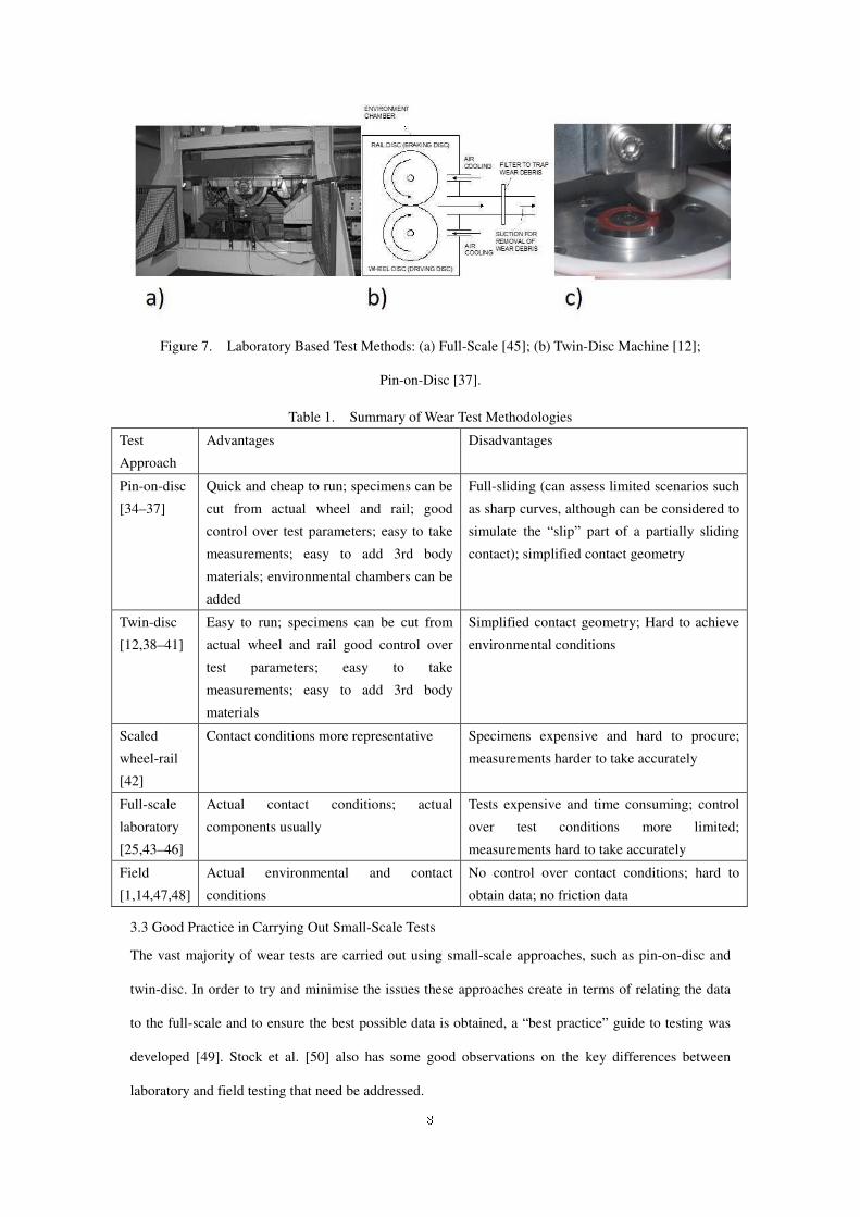
Figure 7. Laboratory Based Test Methods: (a) Full-Scale [45]; (b) Twin-Disc Machine [12];
Pin-on-Disc [37].
Table 1. Summary of Wear Test Methodologies
Test
Approach
Advantages Disadvantages
Pin-on-disc
[34–37]
Quick and cheap to run; specimens can be
cut from actual wheel and rail; good
control over test parameters; easy to take
measurements; easy to add 3rd body
materials; environmental chambers can be
added
Full-sliding (can assess limited scenarios such
as sharp curves, although can be considered to
simulate the “slip” part of a partially sliding
contact); simplified contact geometry
Twin-disc
[12,38–41]
Easy to run; specimens can be cut from
actual wheel and rail good control over
test parameters; easy to take
measurements; easy to add 3rd body
materials
Simplified contact geometry; Hard to achieve
environmental conditions
Scaled
wheel-rail
[42]
Contact conditions more representative Specimens expensive and hard to procure;
measurements harder to take accurately
Full-scale
laboratory
[25,43–46]
Actual contact conditions; actual
components usually
Tests expensive and time consuming; control
over test conditions more limited;
measurements hard to take accurately
Field
[1,14,47,48]
Actual environmental and contact
conditions
No control over contact conditions; hard to
obtain data; no friction data
3.3 Good Practice in Carrying Out Small-Scale Tests
The vast majority of wear tests are carried out using small-scale approaches, such as pin-on-disc and
twin-disc. In order to try and minimise the issues these approaches create in terms of relating the data
to the full-scale and to ensure the best possible data is obtained, a “best practice” guide to testing was
developed [49]. Stock et al. [50] also has some good observations on the key differences between
laboratory and field testing that need be addressed.
9
From this key factors to pay attention to in carrying out a test are:
• use an adequate number of cycles – has steady state wear been achieved? (see [51] for some
good observations on this topic)
• if possible create representative environmental conditions (easier on a pin-on-disc machine
as some have this incorporated)
• cool specimens – when applying multiple cycles to the same contact surface the temperature
rises above that in the field and material properties may change and/or third-body layers
(oxides) become thicker
• manufacture specimens from actual wheel and rail and from the right place to get
representative properties and finish to achieve the right roughness
• use representative contact conditions for the situation you are simulating, it is best to test
across a range of conditions for generating data for models
• where third-body materials are being applied, scale the application to mimic field rates
Important data to collect is shown in Table 2.
Table 2. Recommended Measurements for Wear Tests (adapted from Lewis et al. [49])
Pre-Test Measurements
• Mass (after cleaning)
• Roughness
• Surface hardness
• Surface images
• Sub-surface hardness (dummy disc)
• Sub-surface images before deformation (dummy disc)
Measurements during Test
• Friction
• Load and slip
• Room temperature and humidity
• Wear (either using appropriate
technology or by stopping test
periodically)
• Contact temperature
• Any unusual behaviour of test specimens i.e. change
in noise (frequency, amplitude), visible change in
wear debris, visible change of test specimen surface
Post Test Analysis
• Disc mass
• Surface images
• Roughness
• Surface hardness
• Sub-surface deformation
• Sub-surface hardness gradient
• Third-body layer thickness and composition
• Wear debris characteristics
4 Wear characteristics in wheel-rail contact under environmental conditions
As already mentioned, wheel-rail contact is an open system contact. Thus wheel-rail wear is subjected
to environmental conditions which may differentiate it from other well studied tribological systems. In
10
this section, the influence of some common environmental factors, e.g., water, humidity, temperature,
leaves and iron oxides of the wheel rail wear is discussed.
4.1 influence of water, humidity and temperature
Rainfall is the most common form of water that appears on the rails. Water creates a natural lubricating
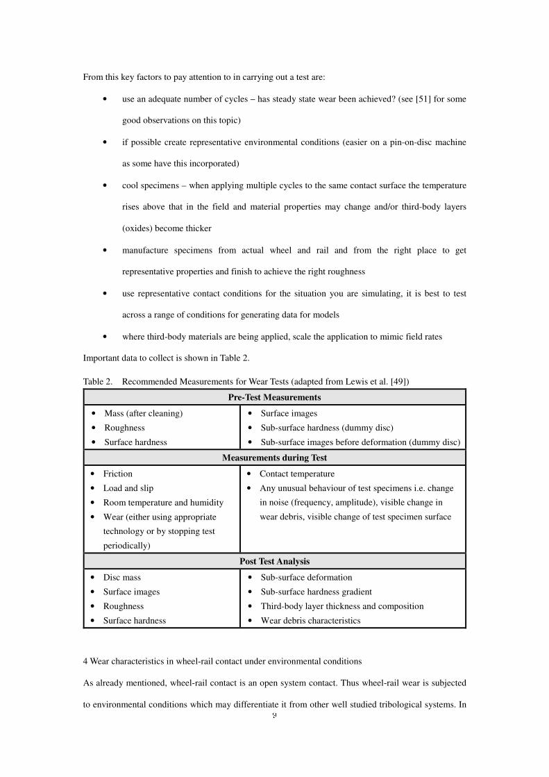
layer between the wheel and the rail to reduce wear. Fig. 8 illustrates the influence of precipitation on
the rail wear rates as measured from the field [9]. One may attribute the low wear rate to the reduction
of friction due to water. As pointed out by Hardwick et al. [32], the actual wear rate under water
lubricated conditions is much lower than simply reducing the coefficient of friction from 0.5 to 0.2
based on the Tγ/A approach. Some other factors can also influence the interface, such as humidity and
temperature, which may not be as obvious as water. The effect of humidity was first recognized by the
serious adhesion loss in the mornings, particularly for the first train. Work was performed using a
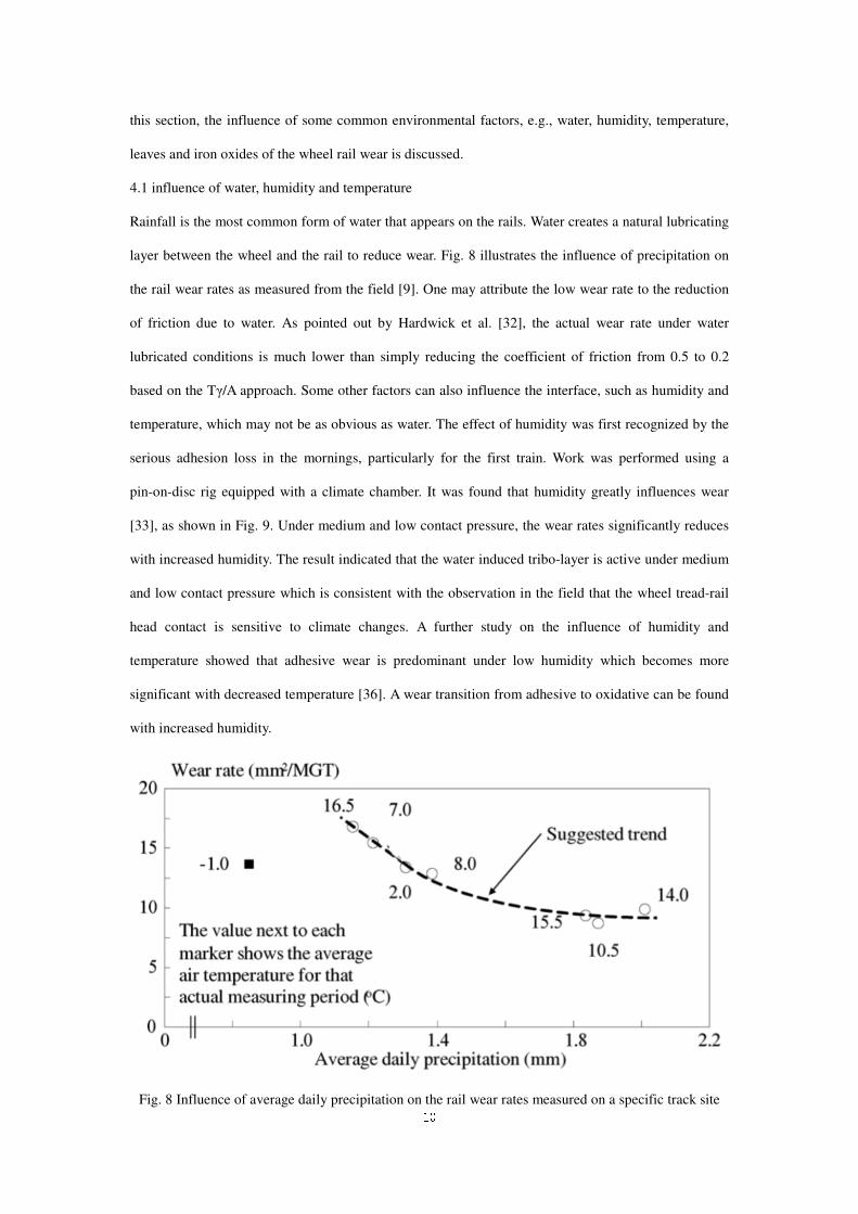
pin-on-disc rig equipped with a climate chamber. It was found that humidity greatly influences wear
[33], as shown in Fig. 9. Under medium and low contact pressure, the wear rates significantly reduces
with increased humidity. The result indicated that the water induced tribo-layer is active under medium
and low contact pressure which is consistent with the observation in the field that the wheel tread-rail
head contact is sensitive to climate changes. A further study on the influence of humidity and
temperature showed that adhesive wear is predominant under low humidity which becomes more
significant with decreased temperature [36]. A wear transition from adhesive to oxidative can be found
with increased humidity.
Fig. 8 Influence of average daily precipitation on the rail wear rates measured on a specific track site
11
[9]. Wear rate calculation can be found in the Appendix.
Fig. 9 Wear maps of wheel rail contact at a relative humidity of 30% (a) and 80% (b) [33]. Wear rate
calculation can be found in the Appendix.
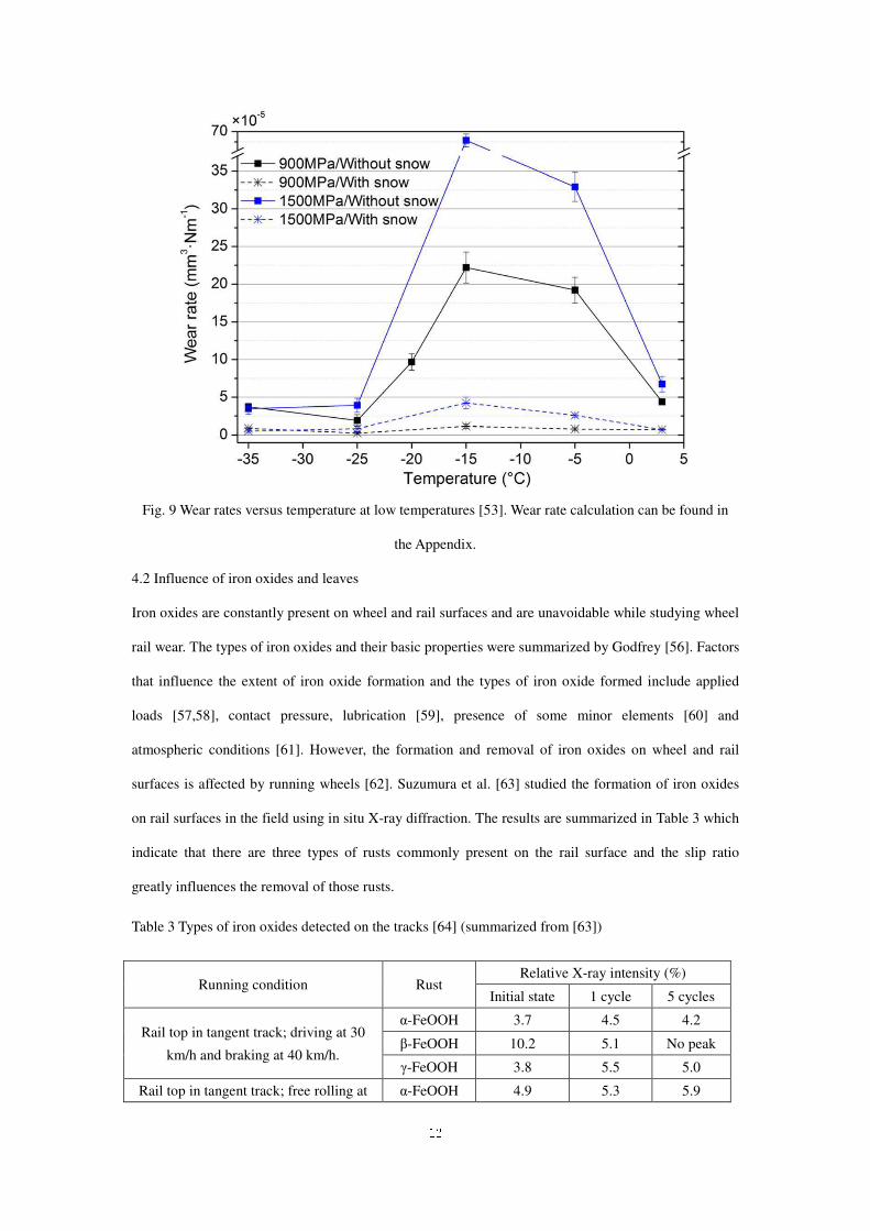
In some geographical areas, wheel and rail wear under low temperatures are crucial since water
transitions to snow or ice. Lyu et al. [52] and Olofsson and Lyu [53] studied the wheel rail wear
focusing on low temperature, as shown in Fig. 10. When snow is present, snow particles are melting
and forming a liquid-like layer under pressure, which facilitates oxidation. Thus the wear is reduced
due to an oxide layer. In the absence of snow, the material brittleness is the dominating factor in the
temperature range from 3°C to −15°C since cracks were formed leading to crushed wear debris which
increased abrasion. When the temperature is extremely low (< −25°C), an ice layer was condensed,
which absorbed a lot of energy in contacting. Therefore, the wear is very low. However, Ma et al. [54]
reported that wear rates of rail material at low temperatures (-15°C, -30°C, and -40°C) are about double
that at room temperature using a twin-disc rig. The results also showed that the wear mechanism is
transformed from abrasive wear at room temperature to adhesive wear at low temperatures. Meanwhile,
as the temperature decreases from 20°C to -40°C, the content of oxide in the debris decreases [55].
12
Fig. 9 Wear rates versus temperature at low temperatures [53]. Wear rate calculation can be found in
the Appendix.
4.2 Influence of iron oxides and leaves
Iron oxides are constantly present on wheel and rail surfaces and are unavoidable while studying wheel
rail wear. The types of iron oxides and their basic properties were summarized by Godfrey [56]. Factors
that influence the extent of iron oxide formation and the types of iron oxide formed include applied
loads [57,58], contact pressure, lubrication [59], presence of some minor elements [60] and
atmospheric conditions [61]. However, the formation and removal of iron oxides on wheel and rail
surfaces is affected by running wheels [62]. Suzumura et al. [63] studied the formation of iron oxides
on rail surfaces in the field using in situ X-ray diffraction. The results are summarized in Table 3 which
indicate that there are three types of rusts commonly present on the rail surface and the slip ratio
greatly influences the removal of those rusts.
Table 3 Types of iron oxides detected on the tracks [64] (summarized from [63])
Running condition Rust Relative X-ray intensity (%)
Initial state 1 cycle 5 cycles
Rail top in tangent track; driving at 30
km/h and braking at 40 km/h.
α-FeOOH 3.7 4.5 4.2
β-FeOOH 10.2 5.1 No peak
γ-FeOOH 3.8 5.5 5.0
Rail top in tangent track; free rolling at α-FeOOH 4.9 5.3 5.9
13
10 km/h. β-FeOOH 8.4 8.5 7.1
γ-FeOOH 7.5 9.7 9.1
Rail gauge of the high rail; driving at 10
km/h and braking at 15 km/h
α-FeOOH 6.7 4.2 2.3
β-FeOOH 16.3 6.8 No peak
γ-FeOOH 7.5 5.9 No peak
Beagley pioneered the laboratory tests that study the influence of iron oxides in the 1970s by mixing
Fe2O3 with fluids [65,66]. Other researchers followed a similar procedure to study the influence of iron
oxides on friction and wear [37,67,68]. However, iron oxides created by manual mixing are still unlike
what is found in the field. Sone et al. [69] proposed a surface treatment for generating iron oxide
surfaces similar to those obtained in the field. Zhu et al. [33,70–72] and Lyu et al. [36] followed the
surface treatment procedure and conducted a series of laboratory tests using twin-disc and pin-on-disc
rigs. The results indicated that three-body abrasion is the dominating wear mechanism. In general, a
thin oxide layer containing a small amount manganese carbide can reduce wear under wet conditions
due to a protective layer that is formed. A thick oxide layer which contains maghemite, lepidocrocite,
and goethite significantly increases wear rates and surface roughness. A comprehensive review
focusing on the iron oxides can be found in Zhu [64].
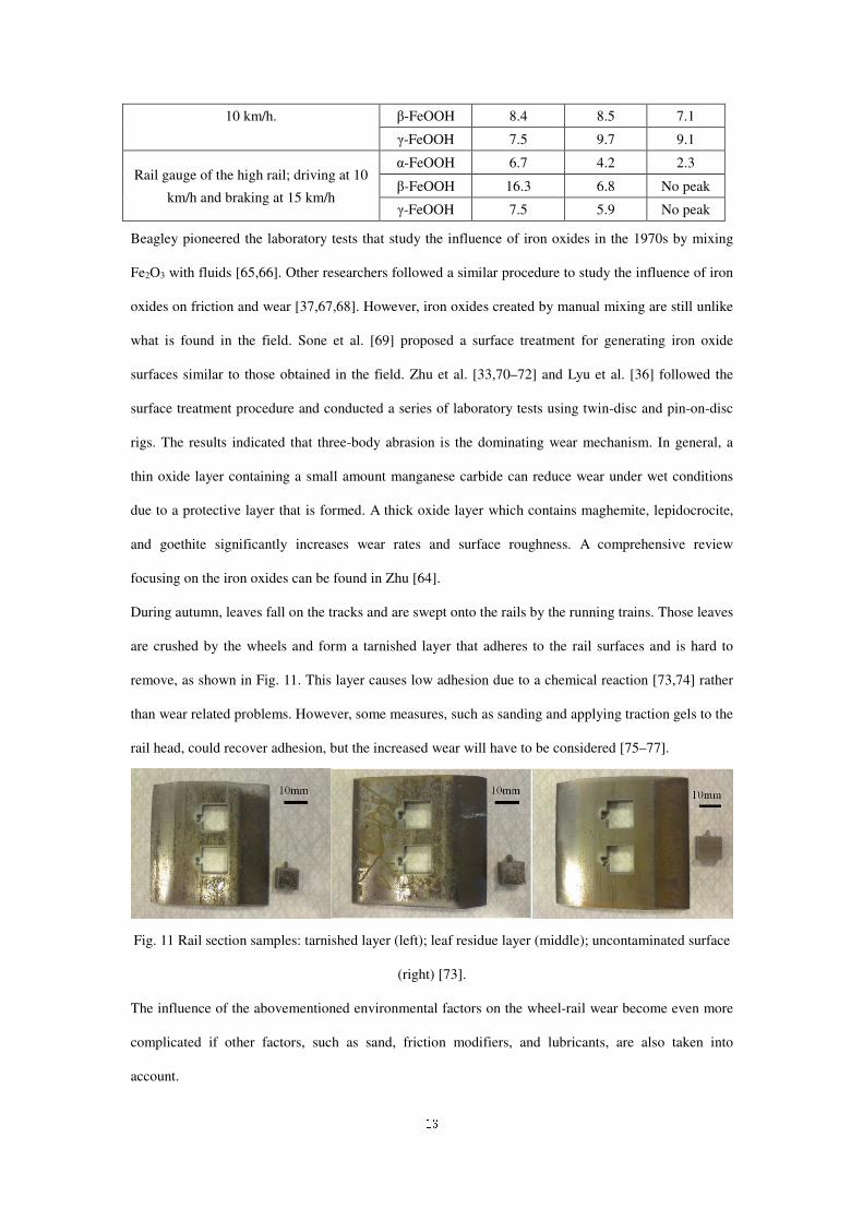
During autumn, leaves fall on the tracks and are swept onto the rails by the running trains. Those leaves
are crushed by the wheels and form a tarnished layer that adheres to the rail surfaces and is hard to
remove, as shown in Fig. 11. This layer causes low adhesion due to a chemical reaction [73,74] rather
than wear related problems. However, some measures, such as sanding and applying traction gels to the
rail head, could recover adhesion, but the increased wear will have to be considered [75–77].
Fig. 11 Rail section samples: tarnished layer (left); leaf residue layer (middle); uncontaminated surface
(right) [73].
The influence of the abovementioned environmental factors on the wheel-rail wear become even more
complicated if other factors, such as sand, friction modifiers, and lubricants, are also taken into
account.
14
Some important references mentioned in the section are summarized in Table 4.
Table 4 Summary of published papers on the influence of environmental conditions on wheel-rail wear
Reference Experimental
methods
Environment
al factors
Effects
Nilsson [9] Field
measurements
Water Increased daily precipitation reduces rail wear
Hardwick et
al. [32]
Twin-disc Water Tγ/A wear results cannot apply to the water
lubricated condition directly.
Zhu et al. [33]
Lyu et al. [36]
Pin-on-disc Humidity
and
temperature
In general, increased humidity reduces wear rate. The
trend becomes more significant with decreased
temperature.
Lyu et al. [52]
Olofsson and
Lyu [53]
Pin-on-disc Low
temperature
Presence of snow significantly reduces wear due to
oxidation. Under extremely low temperature, the
process of an ice layer condensing absorbs the
contacting energy, leading to low wear.
Ma et al. [54] Twin-disc Low
temperature
The wear rates of the rail material increase twice. The
wear mechanism is adhesive wear.
Suzumura et
al. [63]
Field
measurements
Iron oxides Iron oxides on rail surfaces were first measured in
situ. The influence of running conditions on the iron
oxides was studied.
Sone et al.
[69]
Laboratory
surface
treatments
Iron oxides They provided a procedure of surface treatments to
generate iron oxides similar to those found in the
field.
Zhu et al.
[71,72]
Lyu et al. [36]
Twin-disc and
pin-on-disc
Iron oxides Results indicated that three-body abrasion is a
dominating wear mechanism. In general, a thin oxide
layer can reduce wear under wet conditions due to a
protective layer formed. A thick oxide layer increases
wear rates and surface roughness.
Zhu et al. [73] Field Leaves The mechanism of low adhesion caused by leaves is
15
Cann [74] measurements
and
ball-on-disc
due to a chemical reaction between the leaves and the
rail materials.
5 Rolling contact fatigue under environmental conditions
Rolling contact fatigue damage is a major form of wheel-rail damage. Statistics showed that RCF
damage accounted for 41% of all tread damage [54]. The main failure phenomena of wheel-rail RCF
includes spalling, squat, crack, corrugation, flange wear at the interface between the wheel and the rail
and side wear and fracture on the rail. These destructive phenomena are related to many factors, such
as the motion behavior of the wheel-rail, the friction coefficient, the conditional factors (such as surface
damage [78], rolling directions [79], rough surface [80], and so on), the wheel-rail materials, the
“congenital” defects left by processing and the structural form of rail vehicles. As was already
mentioned, environmental factors also greatly affect the RCF.
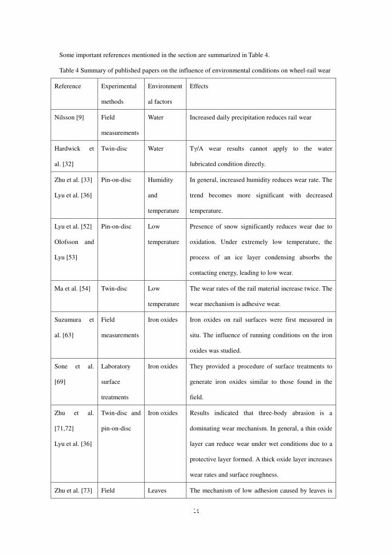
5.1 Influence of ambient temperature and humidity
At high latitudes or in cold areas, the ambient temperature is as low as -40~-50°C in the winter. At low
temperatures, the pearlite in the rail material becomes smaller and irregularly arranged [81,82] while
the tensile strength and the yield strength of the material increases [81,83]. Under such conditions, the
crack growth rate increased and the crack length became longer. This is caused by the brittleness of the
material increasing with the uneven microstructure of the material in a low temperature environmental
condition, while the mode of material damage is transformed from a shear-dominated (ductile) fracture
mode to a cleavage dominated (brittle) fracture mode [81]. Ma et al. [54] reported that -15°C was close
to the ductile-brittle transition temperature (DBTT) which caused severe RCF damage on the surface,
as shown in Fig. 12. High ambient temperature does not significantly affect RCF as much as flash
temperature does which can easily increase to several hundred degrees [84,85]. However, it is related to
the running conditions which are beyond the topic of this paper.
Fig. 12 The influence of ambient temperature on the fatigue crack growth [81] at: a) room temperature;
b) -15°C; c) -30 and -40 °C.
16
The RCF life of the wheel and rail decreases with the increase of ambient humidity. In some practical
railway lines, the RCF damage of the rail surface is more serious under high humidity and high sulfur
conditions [86]. The humidity and temperature of the condition are closely related. In the laboratory,
the ambient humidity decreases with the decrease of temperature [82]. However, there are few studies
on the RCF of the wheel-rail under different humidity conditions.
5.2 Influence of water
In general, the damage of the wheel and rail surfaces is exacerbated by water at the wheel-rail interface,
while the RCF life is also reduced. On one hand, the liquid accelerated the expansion of the fatigue
crack on the surface of the material. On the other hand, the large amount of wear between the wheel
and rail in the dry state was beneficial for removing the fatigue crack in the shallow surface of the
material [87]. In earlier studies, cracks were believed to be generated only on the driven surface and
expanded in the direction of the loading force [87]. In subsequent wheel-rail rolling tests, cracks were
found on both surfaces of the two specimens. The experimental results showed that the RCF life of the
driven wheel was higher than that of the driving wheel [88]. When the crack under wet conditions was
closed under pressure, crack propagation was accelerated under the action of hydraulic pressure.
Therefore, it was easier to find aggravation of the damage on the surface of the driven wheel under the
wet condition [87]. Moreover, the water reduced the adhesion coefficient between the wheel and the
rail and delayed the generation of surface cracks [89]. When the slip ratio was zero, it was difficult to
observe the crack on the surface of specimens due to the low adhesion force [90]. The propagation of
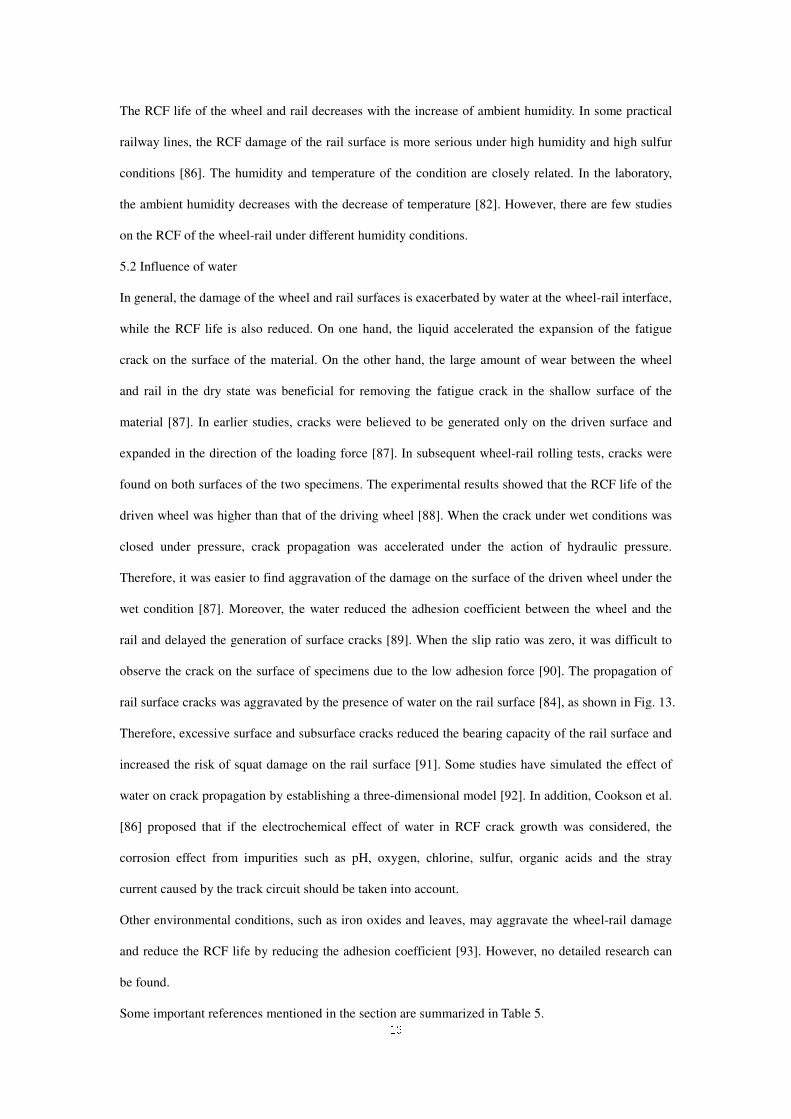
rail surface cracks was aggravated by the presence of water on the rail surface [84], as shown in Fig. 13.
Therefore, excessive surface and subsurface cracks reduced the bearing capacity of the rail surface and
increased the risk of squat damage on the rail surface [91]. Some studies have simulated the effect of
water on crack propagation by establishing a three-dimensional model [92]. In addition, Cookson et al.
[86] proposed that if the electrochemical effect of water in RCF crack growth was considered, the
corrosion effect from impurities such as pH, oxygen, chlorine, sulfur, organic acids and the stray
current caused by the track circuit should be taken into account.
Other environmental conditions, such as iron oxides and leaves, may aggravate the wheel-rail damage
and reduce the RCF life by reducing the adhesion coefficient [93]. However, no detailed research can
be found.
Some important references mentioned in the section are summarized in Table 5.
17
Fig. 13 Mechanism of crack propagation by the pressure of a trapped fluid [84].
Table 5 Summary of published papers on the influence of environmental conditions on RCF
References Experimental
methods
Environmental
factors
Effects
Ma et al. [81] Twin-disc Low
temperature
The propagation speed of the cracks and
the length of RCF cracks increases.
Franklin et al.
[94]
Wang et al.
[90]
Twin-disc Water
Water exacerbates RCF damage. RCF
damage exacerbates with the increase of
slip under water lubricated conditions.
Bogdański and
Lewicki [92]
Numerical
simulation Liquid
The model was used to estimate the 3D
crack front loading enhancements due to
the action of the “liquid entrapment
mechanism”.
Cookson and
Mutton [86]
Literature
review
Water and
oxygen
contamination
Water can lead to local corrosion and
hydrogen uptake in the rail, further
increasing the likelihood of cracking.
6 Some measures to mitigate wear
There are two ways to mitigate wheel-rail wear. One is to lubricate the interface and the other is to
upgrade materials, both of which are discussed in the following. It is noted that the effect of lubricants
will be discussed from wear and RCF problems seen from railway lines rather than discussing
lubricants and lubricating theory.
6.1 Lubricant
18
As mentioned in Section 2, reliable lubrication of the gauge face of the high rail on moderate to tight
curves has been shown to reduce wheel and rail wear by a considerable amount. Most modern rail
operators with flat bottomed or ballasted tracks employ grease as a lubricating medium due to its
tackiness and thus ability to adhere to the rail [95]. The grease is supplied from the side of the track by
automatic distributors which are activated by passing vehicles. The standing grease is then collected by
the passing wheel flange and carried through the corner. The reliability of modern trackside lubricators
has meant that this method of lubricating has become common. However, a continuous, uninterrupted
supply of lubrication is required for this method to remain effective. Research has shown that
intermittent lubrication causes a drastic increase of the wear rate of the rail and wheel and if continuous
lubrication is not achieved the long term wear rate can be higher than not lubricating at all [96]. A
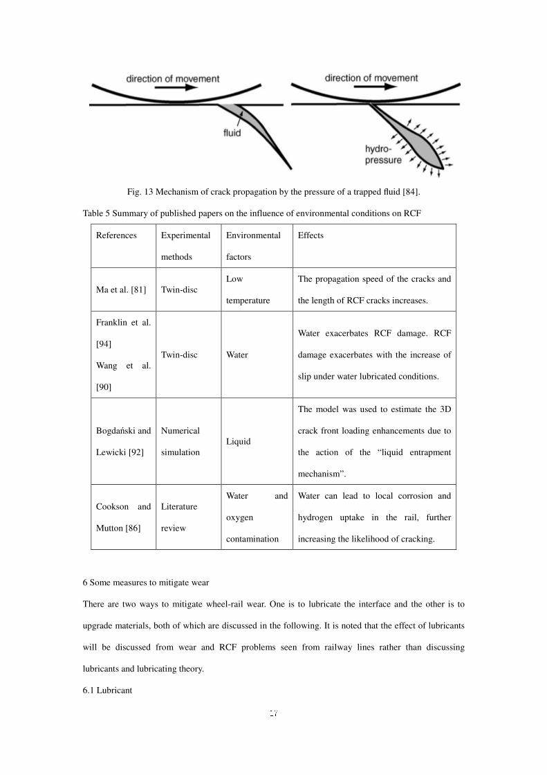
dramatic increase is seen in the wear rate with each subsequent test as shown in Fig. 14. What is more
striking is the increase in wear of both the wheel and the rail after subsequent tests, which in most cases
is higher than the un-lubricated reference. This suggests that it may be better to not lubricate certain
curves if a 100% reliable lubrication system cannot be guaranteed.
Fig. 14 Wear rate of wheel (W) and rail (R) discs after subsequent grease lubrication starvation tests
(repeated on a single pair of discs 5 times) compared to typical un-lubricated (Dry) discs tested under
the same conditions, a) and b) show two of the different brands of grease tested [96]. Wear rate
calculation can be found in the Appendix.
Fletcher and Beynon [97] performed a series of twin-disc tests and found that intermittent application
of grease accelerated RCF crack growth in the discs leading to rapid failure. Hardwick et. al. [32]
performed a twin-disc test and found that un-interrupted lubrication prevents ratcheting from occurring
and hence RCF cracks cannot form. However, if the supply of lubricant is stopped and the contact
conditions allowed to return to dry/ un-lubricated then ratcheting will occur and cracks will form.

19
Fletcher and Beynon [97] put forward a hypothesis that RCF cracks in the rail discs were being
lubricated by entrapped grease which is causing an increase in the shear stress at the crack tip thus
accelerating the crack growth. Wang et al. [98] found the presence of liquid could exacerbate the wear
and RCF in the wheel and rail. Lubricants with high viscosity enhance hydraulic crack growth leading
to many branch cracks.
Another phenomenon which has been highlighted by network operators and researchers is that the
ability of trackside grease lubricators to effectively lubricate any particular curve is dependent on the
types of vehicles traversing that curve whereby some vehicles will collect the standing grease but
others will not [95,99].
A potential solution to this would be the adoption of solid lubricants which are applied from on board
the vehicle. Research related to solid lubrication is rare but Chen et. al. [100] tested different lubricants
including solid lubricants. It was found that solid friction modifier is the most effective type at reducing
curving forces and corrugation.
Some important references mentioned in the section are summarized in Table 6.
Table 6 Summary table of published papers on effects of lubricants
Reference Measures Effects of lubricants
Temple et al. [95]
Burtow and Temple
[99]
Dynamic
simulation,
small-scale and
full-scale testing
Grease pick-up mechanism is discussed and the
installation of a trackside grease dispensing system
needs to be tailored to the particular type of rolling
stock being operated in order for optimal functioning.
Lewis et al. [96]
Fletcher and Beynon
[97]
Hardwick et al. [32]
Twin-disc rig Continuous lubrication is very important to reduce
wear and damage. Intermittent application of grease
accelerates RCF crack growth in the discs leading to
rapid failure.
Chen et al. [100] Twin-disc rolling
contact machine
Solid friction modifier is the most effective type at
reducing curving forces and corrugation.
6.2 Laser cladding
Compared to the lubricants which have been widely used in railway lines, laser cladding is a promising
technology to reduce wheel-rail wear. Laser cladding is not a new technology, which is used for
20
enhancing the mechanical properties or repairing many engineering components [101,102]. Laser
cladding is a hard facing technique which uses laser energy to melt the powders of atomized metal and
metallurgically bond it to the surface of a substrate.
The application of laser cladding in rails started from a European frame research project INFRA-STAR
[103–106]. This project investigated the application of a laser cladding process to rails for the purpose
of preventing rolling contact fatigue (RCF) damage and to reduce squeal noise in curved tracks using
both laboratory and field tests.
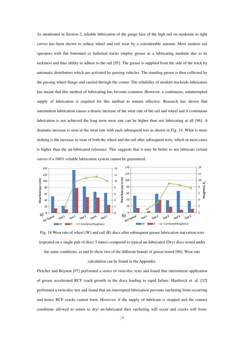
Fig. 14 a) Schematic of a typical laser cladding unit; b) a section of clad rail. [107]
Small scale rolling sliding tests have been performed by many researchers to study the influence of
various cladding materials (mostly steel) on the wear and RCF resistance of rails [108–115]. Results
indicated that clad rails generally have a higher wear and RCF resistance compared to unclad rails.
However, some results may show variations depending on contact conditions and laser cladding quality.
Lai et al. [107,116,117] performed a study from a material aspect by cladding several materials on the
actual rail surface, as shown in Fig. 14. Different laser cladding processing parameters, including heat
treatment and laser cladding direction are considered to identify the optimum laser cladding process for
ideal microstructures which may result in high wear and RCF resistance.
Lewis et al. [118] carried out full-scale testing on laser clad one-meter rail track using a full-scale
wheel-rail test rig. They measured wear of clad track and lipping resistance of insulated block joints.
They found that the wear rate of the clad samples is between 78–89% lower than that of the reference
and cladding either side of an insulated block joint greatly improved its lipping resistance. Hernández
et al. [119] reported a full-scale field track test on laser cladded thermite welds using Facility for
Accelerated Service Testing (FAST) at Transportation Technology Center, Inc. (TTCI), USA. Results
indicated that claddings survived the test for up to 42 MGT in a full scale-heavy haul environment,
21
which is a 14 times improvement from previous work.
It has been shown that laser cladding rails with selected cladding materials and cladding processing
parameters can improve its wear and RCF resistances. Limited data, other than microstructural analysis
and the hardness measurements, is available on the mechanical properties of the claddings and the
HAZs. Those properties are not only crucial for the strength and deforming behaviours of the clad rails
but also important for numerically predicting the performance of the components under cyclic rolling
contact [120,121]. Moreover, residual stress is one of the critical parameters concerning the fatigue
behaviour of tribological components. Tensile residual stress near the surface will assist fatigue crack
initiation and propagation while compressive residual stress will have the negative effect. Laser
cladding could also be an effective technique to repair and maintain surface damaged wheels while the
bonding interface between the cladding and bulk materials is very critical [122]. Practically, repairing
wheels by laser cladding can be carried out in workshops, which might be more flexible and
cost-effective than repairing rails.
Some important references mentioned in the section are summarized in Table 7.
Table 7 Summary of published papers on laser cladding in rail/wheel systems.
Reference Cladding material Experimental
method
Effect of laser cladding
Hiensch et al.
[104]
Franklin et al.
[106]
Clare et al.
[108,109]
Lewis et al.
[110,111]
Fu et al. [112]
Wang et al. [113]
Guo et al. [114]
Roy et al [115]
Duroc 222, Duroc 508 Co-Cr
alloys, nickel alloy, Stellite 6,
maraging steel, Hadfield
steel, 316 stainless steels,
Manganese Steel, martensitic
stainless steel, TWIP Steel,
NiCrBSi, Co-based alloy,
Fe-based alloy, 410L
stainless steel, SS420
stainless steel.
Scaled
rolling-sliding test
rig
In general, the wear and RCF
resistance of the clad rail
materials are increased. But it
also depends on the cladding
materials and cladding
processing parameters. Many
studies reported that Stellite 6
is a promising rail clad
material.
Hiensch et at.
[103]
Duroc 222 and Duroc 508
Co-Cr alloys
Field test on
straight rail track
Increased wear and RCF
resistance
Lewis et al. [118] Martensitic stainless steel
and Stellite 6
A full-scale
laboratory test
Lower wear rate and
increased lipping resistance.
Stellite 6 is a suitable laser
cladding material.
Hernández et al. A undisclosed cladding Full-scale track test Claddings survive the test for
22
[119] material selected based on its
superior resistance to
cracking during cooling
using Facility for
Accelerated
Service Testing
(FAST) at TTCI,
USA
up to 42 MGT in a full
scale-heavy haul
environment, which is a 14
times improvement from
previous work. Proper
heating and cooling prior and
post laser cladding is one of
the key factors for the
improved field test.
Lai et al.
[107,116,117]
410L stainless steel, SS420
stainless steel, Stellite 6 and
Stellite 21
Microstructural
characterization,
shear punch test
Laser claddings have
comparable or better
mechanical properties than
the un-cladded rail. Proper
post-heat treatment can
prevent the formation of
brittle martensite in HAZ.
7 Concluding remarks and future trends
This paper presented a literature review on wheel-rail wear under environmental conditions. Some
basic information on wheel and rail wear was presented, including contact conditions, typical wear
characteristics, and forms of environmental exposures. Wheel rail contact is a typical tribological
system with features that make the system unique and complicated. Experimental methodology was
also discussed, which helps not only to understand the fundamentals of wheel-rail wear but also to
develop measures in the field. The advantages and disadvantages of wear testing methodologies,
including the pin-on-disc, twin-disc, scaled wheel-rail, full-scale laboratory and field, were compared
in detail. Recommended measurements for wear tests were also presented. It is important to develop
standards to measure wheel-rail wear and RCF to evaluate new materials and friction modifiers.
Moreover, such standardized tests could narrow the gap between laboratory tests and reality. However,
much work needs to be performed from both technical and application aspects.
The influence of environmental factors, such as temperature, humidity, water, and leaves on wheel-rail
wear and RCF were presented. The environmental phenomena in the field have been recognized for a
long time but only until recently have people from both academia and industry realized the importance
of these phenomena and started to investigate their mechanisms and influence. As can be found in this
review, most of the studies were performed to investigate a single factor on wear and RCF behavior.
However, the environmental factors are combined in the field which makes their influences even harder
23
to understand. Compared with wear, the influence of humidity and iron oxides on RCF is not well
studied. On the other hand, the interaction of wear and RCF is crucial. Wear can be used to remove
cracks if it can be accurately controlled. Typically, RCF is more severe under lubricated conditions than
under dry conditions. Therefore, there is a trade-off between reducing wear and removing RCF. Further
studies taking both factors into account will be very useful to solve many problems.
Lubricants are widely used on railway lines to reduce wear while laser cladding is currently considered
to be a promising technology to enhance wheel and rail materials. As already mentioned, laser cladding
to repair wheels and enhance some rail sections will be more flexible and cost-effective than cladding
the whole rail. From the application point of view, more field test research similar to those completed
by Hernández et al. [119] will be the key step to convince the railway industry to apply the laser
cladding technique to recover and enhance the wear and rolling contact fatigue resistance of the rails
and the wheels.
Appendix
The wear rates presented in Figs. 4(a), 8, 9, 14 have inconsistent units due to different test rigs used and
some practical reasons. The equations used to calculate wear rates are shown in the following table.
Table 8 Wear rate calculation in the articles
Wear rate unit Wear rate calculation Notes
mm2/MGT in
Fig. 4 (a)
Volumetric loss of the rail/applied load
1 million gross tons (MGT) = 109 kg.
MGT describes the total weight of
rail vehicle which is commonly used
in railway operations.
kg/m in Fig. 8 Mass loss of the sample/sliding distance Used in pin-on-disc testing.
mm3/N•m in
Fig. 9
Volumetric loss of the sample/(sliding
distance × applied load)
Used in pin-on-disc testing.
mm3/cycle in
Fig. 14
Volumetric loss of the sample/running
cycles
Used in twin-disc testing
Funding
The work was supported by National Natural Science Foundation of China [grant numbers 51890881

24
and 51775486], National Key R&D Program of China [SQ2018YFB200029-04], Zhejiang Province
Qianjiang Talent Program [QJD1702027].
References
[1] Olofsson, U., and Nilsson, R., 2002, “Surface Cracks and Wear of Rail: A Full-Scale Test on a
Commuter Train Track,” Proc. Inst. Mech. Eng. Part F J. Rail Rapid Transit, 216(4), pp. 249–
264.
[2] Lewis, R., and Olofsson, U., eds., 2009, Wheel-Rail Interface Handbook, Woodhead publishing
limited.
[3] Zhu, Y., 2013, “Adhesion in the Wheel – Rail Contact,” PhD thesis, Royal Institute of
Technology, KTH, Stockholm, Sweden.
[4] Marshall, M. B., Lewis, R., Dwyer-Joyce, R. S., Olofsson, U., and Björklund, S., 2006,
“Experimental Characterization of Wheel-Rail Contact Patch Evolution,” J. Tribol., 128(3), p.
493.
[5] Zhu, Y., and Olofsson, U., 2014, “An Adhesion Model for Wheel – Rail Contact at the Micro
Level Using Measured 3d Surfaces,” Wear, 314, pp. 162–170.
[6] Zhu, Y., Olofsson, U., and Söderberg, A., 2013, “Adhesion Modeling in the Wheel–rail
Contact under Dry and Lubricated Conditions Using Measured 3D Surfaces,” Tribol. Int., 61,
pp. 1–10.
[7] Zhu, Y., 2013, “Adhesion in the Wheel-Rail Contact,” Royal Institute of Technology, KTH,
PhD thesis, Stockholm, Sweden.
[8] Lewis, R., and Olofsson, U., 2004, “Mapping Rail Wear Regimes and Transitions,” Wear,
257(7–8), pp. 721–729.
[9] Nilsson, R., 2005, “On Wear in Rolling/sliding Contacts,” Licentiate thesis, KTH Royal
Institute of Technology.
[10] Vollebregt, E. A. H., 2012, User Guide for CONTACT, Vollebregt & Kalker’s Rolling and
Sliding Contact Model., Delft, The Netherlands.
[11] Polach, O., 2005, “Creep Forces in Simulations of Traction Vehicles Running on Adhesion
Limit,” Wear, 258(7–8), pp. 992–1000.
[12] Lewis, R., and Dwyer-Joyce, R., 2004, “Wear Mechanisms and Transitions in Railway Wheel
Steels,” Proc. Inst. Mech. Eng. Part J J. Eng. Tribol., 218, pp. 467–478.
25
[13] Jendel, T., 2002, “Prediction of Wheel Profile Wear—comparisons with Field Measurements,”
Wear, 253(1–2), pp. 89–99.
[14] Olofsson, U., and Telliskivi, T., 2003, “Wear, Plastic Deformation and Friction of Two Rail
Steels—a Full-Scale Test and a Laboratory Study,” Wear, 254(1–2), pp. 80–93.
[15] Cantana, F., 1993, “Investigation of Wheel FLange Wear on the Santander FEVE Rail– a Case
Stud,” Wear, 162, pp. 975–979.
[16] Waara, P., 2000, “Wear Reduction Performance of Rail Flange Lubrication,” PhD thesis, Luleå
University of Technology.
[17] Kalousek, J., and Magel, E., 1997, “Modifying and Managing Friction,” Railway Track &
Structures, pp. 5–6.
[18] Arias-Cuevas, O., Li, Z., and Lewis, R., 2011, “A Laboratory Investigation on the Influence of
the Particle Size and Slip during Sanding on the Adhesion and Wear in the Wheel–rail Contact,”
Wear, 271(1–2), pp. 14–24.
[19] Lewis, R., and Dwyer-Joyce, R. S., 2006, “Wear at the Wheel/rail Interface When Sanding Is
Used to Increase Adhesion,” Proc. Inst. Mech. Eng. Part F J. Rail Rapid Transit, 220(1), pp.
29–41.
[20] Huang, W., Cao, X., Wen, Z., Wang, W., and Al., E., 2017, “A Subscale Experimental
Investigation on the Influence of Sanding on Adhesion and Rolling Contact Fatigue of
Wheel/Rail Under Water Condition,” J. Tribol., 139, pp. 1–8.
[21] Cao, X., Huang, W., He, C., and Al., E., 2016, “The Effect of Alumina Particle on Improving
Adhesion and Wear Damage of Wheel/Rail under Wet Conditions,” Wear, 348–349, pp. 98–
115.
[22] Wang, W., Liu, T., Wang, H., and Al., E., 2014, “Influence of Friction Modifiers on Improving
Adhesion and Surface Damage of Wheel/Rail under Low Adhesion Conditions,” Tribol. Int.,
75, pp. 16–23.
[23] Pombo, J., Ambrósio, J., Pereira, M., Lewis, R., and Caterina, R. D., 2010, “A Study on Wear
Evaluation of Railway Wheels Based on Multibody Dynamics and Wear Computation,”
Multibody Syst. Dyn., 24(3), pp. 347–366.
[24] Pombo, J., Ambrósio, J., Pereira, M., Lewis, R., Dwyer-joyce, R., Ariaudo, C., and Kuka, N.,
2011, “Development of a Wear Prediction Tool for Steel Railway Wheels Using Three
26
Alternative Wear Functions,” Wear, 271, pp. 238–245.
[25] Braghin, F., Lewis, R., Dwyer-joyce, R. S., and Bruni, S., 2006, “A Mathematical Model to
Predict Railway Wheel Profile Evolution due to Wear,” Wear, 261, pp. 1253–1264.
[26] Innocenti, M. I. A., and Meli, L. M. E., 2014, “Development of a Model for the Simultaneous
Analysis of Wheel and Rail Wear in Railway Systems,” Multibody Syst. Dyn., 31(2), pp. 191–
240.
[27] Innocenti, A., Marini, L., Meli, E., Pallini, G., and Rindi, A., 2014, “Development of a Wear
Model for the Analysis of Complex Railway Networks,” Wear, 309(1–2), pp. 174–191.
[28] Archard, J. F., 1953, “Contact and Rubbing of Flat Surfaces,” J. Appl. Phys., 24, pp. 981–988.
[29] Burstow, M., 2003, Whole Life Rail Model Application and Development for RSSB:
Development of an RCF Damage Parameter.
[30] Magel, E., Kalousek, J., and Sroba, P., 2014, “Chasing the Magic Wear Rate,” Proceedings of
the Second International Conference on Railway Technology: Research, Development and
Maintenance, Corsica, France.
[31] Rovira, A., Roda, A., Lewis, R., and Marshall, M. B., 2012, “Application of FASTSIM with
Variable Coefficient of Friction Using Twin Disc Experimental Measurements,” Wear, 274–
275, pp. 109–126.
[32] Hardwick, C., Lewis, R., and Eadie, D. T., 2014, “Wheel and Rail wear—Understanding the
Effects of Water and Grease,” Wear, 314(1–2), pp. 198–204.
[33] Zhu, Y., Sundh, J., and Olofsson, U., 2013, “A Tribological View of Wheel-Rail Wear Maps,”
Int. J. Railw. Technol., 2(3), pp. 79–91.
[34] Sundh, J., Olofsson, U., and Sundvall, K., 2008, “Seizure and Wear Rate Testing of Wheel–rail
Contacts under Lubricated Conditions Using Pin-on-Disc Methodology,” Wear, 265(9–10), pp.
1425–1430.
[35] Sundh, J., and Olofsson, U., 2011, “Relating Contact Temperature and Wear Transitions in a
Wheel–rail Contact,” Wear, 271(1–2), pp. 78–85.
[36] Lyu, Y., Zhu, Y., and Olofsson, U., 2015, “Wear between Wheel and Rail A Pin-on-Disc Study
of Environmental Conditions and Iron Oxides,” Wear, 328–329, pp. 277–285.
[37] Lewis, S. R., Lewis, R., Olofsson, U., Eadie, D. T., Cotter, J., and Lu, X., 2012, “Effect of
Humidity, Temperature and Railhead Contamination on the Performance of Friction Modifiers:
27
Pin-on-Disk Study,” Proc. Inst. Mech. Eng. Part F J. Rail Rapid Transit, 227(2), pp. 115–127.
[38] Bolton, P. J., Clayton, P., and Railway, T., 1984, “Rolling-Sliding Wear Damage in Rail and
Tyre Steels,” 93, pp. 145–165.
[39] Krause, H., and Poll, G., 1986, “Wear of Wheel-Rail Surfaces,” Wear, 113, pp. 103–122.
[40] Garnham, J. E., and Beynon, J. H., 1992, “Dry Rolling-Sliding Wear of Bainitic and Pearlitic
Steels,” Wear, 157(1), pp. 81–109.
[41] Wang, W. J., Lewis, R., Yang, B., Guo, L., Liu, Q., and Zhu, M., 2016, “Wear and Damage
Transitions of Wheel and Rail Materials under Various Contact Conditions,” Wear, 362–363,
pp. 146–152.
[42] Kumar, S., and Pransanna, R. D. ., 1984, “Wheel-Rail Contact Wear, Work and Lateral Force
for Zero Angle of Attack-a Laboratory Study,” J. Dyn. Syst. Meas. Control, 106(319–326).
[43] McEwen, I. J., and Harvey, R. F., 1985, “Full-Scale Wheel-on-Rail Testing: Comparisons with
Service Wear and a Developing Theoretical Predictive Model,” Lubr. Eng., 41(2), pp. 80–88.
[44] Stock, R., Eadie, D. T., and Oldknow, K., 2013, “Rail Grade Selection and Friction
Management: A Combined Approach for Optimising Rail-Wheel Contact,” Ironmak. Steelmak.,
40(2), pp. 108–114.
[45] Stock, R., and Pippan, R., 2011, “RCF and Wear in Theory and Practice—The Influence of
Rail Grade on Wear and RCF,” Wear, 271, pp. 125–133.
[46] Heyder, R., and Maedler, K., 2015, “The Influence of Wheel and Rail Material on the Wear of
the Respective Contact Partner,” Proceedings of CM2015 10th International Conference on
Contact Mechanics and Wear of Rail/Wheel Systems.
[47] Steele, R. K., 1982, “Observations of In-Service Wear of Railroad Wheels and Rails under
Conditions of Widely Varying Lubrication,” ASLE Trans., 25(3), pp. 400–409.
[48] Dearden, L., 1960, “The Wear of Steel Rails and Tyres in Railway Service,” Wear, 3, pp. 43–
49.
[49] Lewis, R., Magel, E., Wang, W. J., Olofsson, U., Lewis, S. R., Slatter, T., and Beagles, A.,
2017, “Towards a Standard Approach for Wear Testing of Wheel and Rail Materials,” J. Rail
Rapid Transit, Proc. IMechE, Part F, 231(7), pp. 760–774.
[50] Stock, R., Eadie, D. T., Elvidge, D., and Oldknow, K., 2011, “Influencing Rolling Contact
Fatigue through Top of Rail Friction Modifier Application – A Full Scale Wheel–rail Test Rig
28
Study,” Wear, 271(1–2), pp. 134–142.
[51] Blau, P., 2015, “How Common Is the Steady-State? The Implications of Wear Transitions for
Materials Selection and Design,” Wear, 332–333, pp. 1120–1128.
[52] Lyu, Y., Bergseth, E., and Olofsson, U., 2016, “Open System Tribology and Influence of
Weather Condition,” Sci. Rep., 6, pp. 1–11.
[53] Olofsson, U., and Lyu, Y., 2017, “Open System Tribology in the Wheel – Rail Contact — A
Literature Review,” Appl. Mech. Rev. Rev., 69, pp. 1–10.
[54] Ma, L., Shi, L., Guo, J., Liu, Q., and Wang, W., 2018, “On the Wear and Damage
Characteristics of Rail Material under Low Temperature Environment Condition Temperature
to Adhesive Wear at Low Temperatures,” Wear, 394–395, pp. 149–158.
[55] Shi, L., Ma, L., Guo, J., and Al., E., 2018, “Influence of Low Temperature Environment on the
Adhesion Characteristics of Wheel-Rail Contact,” Tribol. Int., 127, pp. 59–68.
[56] Godfrey, D., 1999, “Iron Oxides and Rust (Hydrated Iron Oxides) in Tribology,” J. Soc. Tribol.
Lubr. Eng., 55(2), pp. 33–37.
[57] Quinn, T. F. ., 1998, “Oxidational Wear Modelling Part III. The Effects of Speed and Elevated
Temperatures,” Wear, 216, pp. 262–275.
[58] Quinn, T. F. ., 2002, “The Oxidational Wear of Low Alloy Steels,” Tribol. Int., 35(11), pp.
691–715.
[59] Dillmann, P., Mazaudier, F., and Hœrlé, S., 2004, “Advances in Understanding Atmospheric
Corrosion of Iron. I. Rust Characterisation of Ancient Ferrous Artefacts Exposed to Indoor
Atmospheric Corrosion,” Corros. Sci., 46(6), pp. 1401–1429.
[60] Kamimura, T., Hara, S., Miyuki, H., Yamashita, M., and Uchida, H., 2006, “Composition and
Protective Ability of Rust Layer Formed on Weathering Steel Exposed to Various
Environments,” Corros. Sci., 48(9), pp. 2799–2812.
[61] de la Fuente, D., Díaz, I., Simancas, J., Chico, B., and Morcillo, M., 2011, “Long-Term
Atmospheric Corrosion of Mild Steel,” Corros. Sci., 53(2), pp. 604–617.
[62] Nakahara, T., Baek, K.-S., Chen, H., and Ishida, M., 2011, “Relationship between Surface
Oxide Layer and Transient Traction Characteristics for Two Steel Rollers under Unlubricated
and Water Lubricated Conditions,” Wear, 271(1–2), pp. 25–31.
[63] Suzumura, J., Sone, Y., Ishizaki, A., Yamashita, D., Nakajima, Y., and Ishida, M., 2011, “In
29
Situ X-Ray Analytical Study on the Alteration Process of Iron Oxide Layers at the Railhead
Surface While under Railway Traffic,” Wear, 271(1–2), pp. 47–53.
[64] Zhu, Y., 2018, “The Influence of Iron Oxides on Wheel–rail Contact: A Literature Review,”
Proc. Inst. Mech. Eng. Part F J. Rail Rapid Transit, 232(3), pp. 734–743.
[65] Beagley, T. M., 1976, “The Rheological Properties of Solid Rail Contaminants and Their
Effect on Wheel/rail Adhesion,” Proc. Instn. Mech. Engrs, 190(39), pp. 419–428.
[66] Beagley, T., McEwen, I., and Pritchard, C., 1975, “Wheel/rail Adhesion—the Influence of
Railhead Debris,” Wear, 33, pp. 141–152.
[67] Hardwick, C., Lewis, R., and Olofsson, U., 2012, “Low Adhesion due to Oxide Formation in
the Presence of NaCl,” Proceedings of 9th International Conference on Contact Mechanics
and Wear of Rail/wheel System, Chengdu, China, pp. 27–30.
[68] Lu, X., Cotter, J., and Eadie, D. T., 2005, “Laboratory Study of the Tribological Properties of
Friction Modifier Thin Films for Friction Control at the Wheel/rail Interface,” Wear, 259(7–12),
pp. 1262–1269.
[69] Sone, Y., Suzumura, J., Ban, T., Aoki, F., and Ishida, M., 2008, “Possibility of in Situ
Spectroscopic Analysis for Iron Rust on the Running Band of Rail,” Wear, 265(9–10), pp.
1396–1401.
[70] Zhu, Y., Olofsson, U., and Chen, H., 2013, “Friction Between Wheel and Rail: A Pin-On-Disc
Study of Environmental Conditions and Iron Oxides,” Tribol. Lett., 52(2), pp. 327–339.
[71] Zhu, Y., Chen, X., Wang, W., and Yang, H., 2015, “A Study on Iron Oxides and Surface
Roughness in Dry and Wet Wheel−rail Contacts,” Wear, 328–329, pp. 241–248.
[72] Zhu, Y., Yang, H., and Wang, W., 2016, “Twin-Disc Tests of Iron Oxides in Dry and Wet
Wheel-Rail Contacts,” Proc. Inst. Mech. Eng. Part F J. Rail Rapid Transit, 230(4), pp.
1066-1076.
[73] Zhu, Y., Olofsson, U., and Nilsson, R., 2012, “A Field Test Study of Leaf Contamination on
Railhead Surfaces,” Proc. Inst. Mech. Eng. Part F J. Rail Rapid Transit, 228(1), pp. 71–84.
[74] Cann, P. M., 2006, “The ‘leaves on the Line’ Problem—a Study of Leaf Residue Film
Formation and Lubricity under Laboratory Test Conditions,” Tribol. Lett., 24(2), pp. 151–158.
[75] Wang, W., Zhang, H., Wang, H., and Al., E., 2011, “Study on the Adhesion Behavior of
Wheel/Rail under Oil, Water and Sanding Conditions,” Wear, 271, pp. 2693–2698.
30
[76] Li, Z., Arias-Cuevas, O., Lewis, R., and Gallardo-Hernández, E. a., 2008, “Rolling–Sliding
Laboratory Tests of Friction Modifiers in Leaf Contaminated Wheel–Rail Contacts,” Tribol.
Lett., 33(2), pp. 97–109.
[77] Arias-Cuevas, O., and Li, Z., 2011, “Field Investigations into the Adhesion Recovery in
Leaf-Contaminated Wheel-Rail Contacts with Locomotive Sanders,” Proc. Inst. Mech. Eng.
Part F J. Rail Rapid Transit, 225(5), pp. 443–456.
[78] Zhao, X. J., Guo, J., Liu, Q. Y., Butini, E., Marini, L., Meli, E., Rindi, A., and Wang, W. J.,
2018, “Effect of Spherical Dents on Microstructure Evolution and Rolling Contact Fatigue of
Wheel/rail Materials,” Tribiology Int., 127, pp. 520–532.
[79] Tyfour, W. R., and Beynon, J. H., 1994, “The Effect of Rolling Direction Reversal on Fatigue
Crack Morphology and Propagation,” Tribol. Int., 27(4), pp. 273–282.
[80] Daves, W., Kubin, W., Scheriau, S., and Pletz, M., 2016, “A Finite Element Model to Simulate
the Physical Mechanisms of Wear and Crack Initiation in Wheel/rail Contact,” Wear, 366–367,
pp. 78–83.
[81] Ma, L., Guo, J., Liu, Q., and Wang, W., 2017, “Fatigue Crack Growth and Damage
Characteristics of High-Speed Rail at Low Ambient Temperature,” Eng. Fail. Anal., 82, pp.
802–815.
[82] Bevan, A., Molyneux-Berry, P., and Eickhoff, B., 2013, “Development and Validation of a
Wheel Wear and Rolling Contact Fatigue Damage Model,” Wear, 307, pp. 100–111.
[83] Wang, Y., Zhou, H., Shi, Y., and Feng, B., 2012, “Mechanical Properties and Fracture
Toughness of Rail Steels and Thermite Welds at Low Temperature,” Int. J. Miner. Metall.
Mater., 19(5), pp. 409–420.
[84] Ekberg, A., and Kabo, E., 2005, “Fatigue of Railway Wheels and Rails under Rolling Contact
and Thermal Loading - an Overview,” Wear, 1288–1300.
[85] Ekberg, A., Åkesson, B., and Kabo, E., 2014, “Wheel/rail Rolling Contact Fatigue-Probe,
Predict, Prevent,” Wear, 314, pp. 2–12.
[86] Cookson, J. M., and Mutton, P., 2011, “The Role of the Environment in the Rolling Contact
Fatigue Cracking of Rails,” Wear, 271, pp. 113–119.
[87] Steenbergen, M., 2016, “Rolling Contact Fatigue in Relation to Rail Grinding,” Wear, 356–357,
pp. 110–121.
31
[88] Tyfour, W. R., Beynon, J. H., and Kapoor, A., 1996, “Deterioration of Rolling Contact Fatigue
Life of Pearlitic Rail Steel due to Dry-Wet Rolling-Sliding Line Contact,” Wear, 197, pp. 255–
265.
[89] Zeng, D. F., Lu, L., Gong, Y. H., Zhang, Y. B., and Zhang, J., 2017, “Influence of Solid
Solution Strengthening on Spalling Behavior of Railway Wheel Steel,” Wear, 372–373, pp.
158–168.
[90] Wang, W. J., Lewis, S. R., Lewis, R., and Al, E., 2017, “The Role of Slip Ratio in Rolling
Contact Fatigue of Rail Materials under Wet Conditions,” Wear, 376–377, pp. 1892–1900.
[91] Al-Juboori, A., Zhu, H., Wexler, D., and Al, E., 2019, “Evolution of Rail Surface Degradation
in the Tunnel: The Role of Water on Squat Growth under Service Conditions,” Eng. Fract.
Mech., 209, pp. 32–47.
[92] Bogdanski, S., and Lewicki, P., 2008, “3D Model of Liquid Entrapment Mechanism for
Rolling Contact Fatigue Cracks in Rails,” Wear, 265, pp. 1356–1362.
[93] Omastan, M., Machatka, M., and Smejkal, D., 2015, “Influence of Sanding Parameters on
Adhesion Recovery in Contaminated Wheel-Rail Contact,” Wear, 322–323, pp. 218–225.
[94] Franklin, F. J., Weeda, G.-J., Kapoor, a., and Hiensch, E. J. M., 2005, “Rolling Contact
Fatigue and Wear Behaviour of the Infrastar Two-Material Rail,” Wear, 258(7–8), pp. 1048–
1054.
[95] Temple, P. D., Harmon, M., Lewis, R., Burtow, M. C., Temple, B., and Jones, D., 2017,
“Optimization of Grease Application to Railway Track.,” Proc. Inst. Mech. Eng. Part F J. Rail
Rapid Transit., 232(5), pp. 1514–1527.
[96] Lewis, S. R., Lewis, R., Evans, G., and Buckley-Johnstone, L. E., 2014, “Assessment of
Railway Curve Lubricant Performance Using a Twin-Disc Tester,” Wear, 314(1–2), pp. 205–
212.
[97] Fletcher, D. I., and Beynon, J. H., 2000, “The Effect of Intermittent Lubrication on the Fatigue
Life of Pearlitic Rail Steel in Rolling/sliding Contact,” Proc. Inst. Mech. Eng. Part F J. Rail
Rapid Transit., 214, pp. 145–158.
[98] Wang, W., Lewis, R., Evans, M., and Liu, Q., 2017, “Influence of Different Application of
Lubricants on Wear and Pre-Existing Rolling Contact Fatigue Cracks of Rail Materials,” Tribol.
Lett., 65(2), pp. 1–15.
32
[99] Burtow, M. C., and Temple, B., 2015, Wheel/rail Interaction for Lubrication.
[100] Chen, H., Fukagai, S., Sone, Y., Ban, T., and Namura, A., 2014, “Assessment of Lubricant
Applied to Wheel/rail Interface in Curves,” Wear, 314, pp. 228–235.
[101] Chen, J., Takezono, S., Li, G., and Tanaka, T., 1995, “Effect of Laser Cladding on Fatigue
Strength of an Alloy Steel,” J. Soc. Mater. Sci. Japan, 44, pp. 343–347.
[102] Sexton, L., Lavin, S., Byrne, S., and Kennedy, A., 2002, “Laser Cladding of Aerospace
Materials,” J. Mater. Process. Tech., 122, pp. 63–68.
[103] Hiensch, E. J. M., Larsson, P.-O., Nilsson, O., Levy, D., Kapoor, A., Franklin, F., Nielsen, J. C.
O., Ringsberg, J. W., and Josefson, B. L., 2005, “Two-Material Rail Development: Field Test
Results Regarding Rolling Contact Fatigue and Squeal Noise Behaviour,” Wear, 258, pp. 964–
972.
[104] Hiensch, E. J. M., Franklin, F. J., Nielsen, J. C. O., Ringsberg, J. W., Weeda, G.-J., Kapoor, A.,
and Josefson, B. L., 2003, “Prevention of RCF Damage in Curved Track through Development
of the Infra-Star Two-Material Rail,” Fatigue Fract. Eng. Mater. Struct., 25, pp. 1007–1017.
[105] Ringsberg, J. W., Franklin, F. J., Josefson, B. L., Kapoor, A., and Nielsen, J. C. O., 2005,
“Fatigue Evaluation of Surface Coated Railway Rails Using Shakedown Theory, Finite
Element Calculations, and Lab and Field Trials,” Int. J. Fatigue, 27(6), pp. 680–694.
[106] Franklin, F. J., Weeda, G.-J., Kapoor, A., and Hiensch, E. J. M., 2005, “Rolling Contact
Fatigue and Wear Behaviour of the Infrastar Two-Material Rail,” Wear, 258, pp. 1048–1054.
[107] Lai, Q., Abrahams, R., Yan, W., Qiu, C., Mutton, P., Paradowska, A., and Soodi, M., 2017,
“Investigation of a Novel Functionally Graded Material for the Repair of Premium
Hypereutectoid Rails Using Laser Cladding Technology,” Compos. Part B Eng., 130, pp. 174–
191.
[108] Clare, A. T., Oyelola, O., Abioye, T. E., and Farayibi, P. K., 2013, “Laser Cladding of Rail
Steel with Co-Cr. Surface Engineering,” Surf. Eng., 29(10), pp. 731–736.
[109] Clare, A. T., Oyelola, O., Folker, J., and Faraybi, P., 2011, “Laser Cladding for Railway Repair
and Preventative Maintenance,” J. Laser Appl., 240, pp. 240-249.
[110] Lewis, S. R., Lewis, R., and Fletcher, D. I., 2015, “Assessment of Laser Cladding as an Option
for Repairing/enhancing Rails,” Wear, 330–331, pp. 581–591.
[111] Lewis, S. R., Fretwell-Smith, S., Goodwin, P. S., Smith, L., Lewis, R., Aslam, M., Fletcher, D.

33
I., Murray, K., and Lambert, R., 2016, “Improving Rail Wear and RCF Performance Using
Laser Cladding,” Wear, 366–367, pp. 268–278.
[112] Fu, Z. K., Ding, H. H., Wang, W. J., Liu, Q. Y., Guo, J., and Zhu, M. H., 2015, “Investigation
on Microstructure and Wear Characteristic of Laser Cladding Fe-Based Alloy on Wheel/rail
Materials,” Wear, 330–331, pp. 592–599.
[113] Wang, W. J., Hu, J., Guo, J., Liu, Q. Y., and Zhu, M. H., 2014, “Effect of Laser Cladding on
Wear and Damage Behaviors of Heavy-Haul Wheel/rail Materials,” Wear, 311(1–2), pp. 130–
136.
[114] Guo, H. ming, Wang, Q., Wang, W. jian, Guo, J., Liu, Q. yue, and Zhu, M. hao, 2015,
“Investigation on Wear and Damage Performance of Laser Cladding Co-Based Alloy on Single
Wheel or Rail Material,” Wear, 328–329, pp. 329–337.
[115] Roy, T., Lai, Q., Abrahams, R., Mutton, P., Paradowska, A., Soodi, M., and Yan, W., 2018,
“Effect of Deposition Material and Heat Treatment on Wear and Rolling Contact Fatigue of
Laser Cladded Rails,” Wear, 412–413, pp. 69–81.
[116] Lai, Q., Abrahams, R., Yan, W., Qiu, C., Mutton, P., Paradowska, A., Fang, X., Soodi, M., and
Wu, X., 2018, “Effects of Preheating and Carbon Dilution on Material Characteristics of
Laser-Cladded Hypereutectoid Rail Steels,” Mater. Sci. Eng. A, 712, pp. 548–563.
[117] Lai, Q., Abrahams, R., Yan, W., Qiu, C., Mutton, P., Paradowska, A., Soodi, M., and Wu, X.,
2019, “Influences of Depositing Materials, Processing Parameters and Heating Conditions on
Material Characteristics of Laser-Cladded Hypereutectoid Rails,” J. Mater. Process. Technol.,
263(July 2018), pp. 1–20.
[118] Lewis, S. R., Lewis, R., Goodwin, P. S., Fretwell-Smith, S., Fletcher, D. I., Murray, K., and
Jaiswal, J., 2017, “Full-Scale Testing of Laser Clad Railway Track; Case Study – Testing for
Wear, Bend Fatigue and Insulated Block Joint Lipping Integrity,” Wear, 376–377, pp. 1930–
1937.
[119] Hernández, F. C. R., Okonkwo, A. O., Kadekar, V., Metz, T., and Badi, N., 2016, “Laser
Cladding : The Alternative for Fi Eld Thermite Welds Life Extension,” 111, pp. 165–173.
[120] Pun, C. L., Kan, Q., Mutton, P., Kang, G., and Yan, W., 2015, “An Efficient Computational
Approach to Evaluate the Ratcheting Performance of Rail Steels under Cyclic Rolling Contact
in Service,” Int. J. Mech. Sci., 101–102, pp. 213–226.
34
[121] Pun, C. L., Kan, Q., Mutton, P., Kang, G., and Yan, W., 2014, “Ratcheting Behaviour of High
Strength Rail Steels under Bi-Axial Compression-Torsion Loadings: Experiment and
Simulation.,” Int. J. Fatigue, 66, pp. 138–154.
[122] Zhu, Y., Yang, Y., Mu, X., Wang, W., Yao, Z., and Yang, H., 2019, “Study on Wear and RCF
Performance of Repaired Damage Railway Wheels : Assessing Laser Cladding to Repair Local
Defects on Wheels,” Wear, 431, pp. 126–136.


![Wheels on Disc Brake Inspection (1).ppt [Read-Only] · an end of life warning • Brake reline should be performed 10. Electronic Pad Wear Sensors 11 In-pad wear sensor and In-pad](https://img.pdfslide.net/doc/110x75/5e23782f13360700d1082a8a/wheels-on-disc-brake-inspection-1ppt-read-only-an-end-of-life-warning-a-brake.jpg)