Embed Size (px)
Citation preview
International Journal of Bridge Engineering (IJBE), Vol.8, No. 1, (2020), pp. 71-85
A REVIEW STUDY OF DELAMINATION IN
COMPOSITE LAMINATED DECKS PLATES
Dr. Osama Mohammed Elmardi Suleiman Khayal
Nile Valley University, Dept. of Mechanical Engineering, Sudan
e-mail: [email protected]
ABSTRACT: Failure analysis of laminated composite decks structures has
attracted a great deal of interest in recent years due to the increased application
of composite materials in a wide range of high-performance structures.
Intensive experimental and theoretical studies of failure analysis and prediction
are being reviewed. Delamination, the separation of two adjacent plies in
composite laminates, represents one of the most critical failure modes in
composite laminates. In fact, it is an essential issue in the evaluation of
composite laminates for durability and damage tolerance. Thus, broken fibers,
delaminated regions, cracks in the matrix material, as well as holes, foreign
inclusions and small voids constitute material and structural imperfections that
can exist in composite structures. Imperfections have always existed and their
effect on the structural response of a system has been very significant in many
cases. These imperfections can be classified into two broad categories: initial
geometrical imperfections and material or constructional imperfections.
KEYWORDS: Delamination, composite laminates, rectangular plates, review
1 INTRODUCTION Composites were first considered as structural materials a little more than three
quarters of a century ago. From that time to now, they have received increasing
attention in all aspects of material science, manufacturing technology, and
theoretical analysis.
The term composite could mean almost anything if taken at face value, since
all materials are composites of dissimilar subunits if examined at close enough
details. But in modern materials engineering, the term usually refers to a matrix
material that is reinforced with fibers. For instance, the term "FRP" which refers
to Fiber Reinforced Plastic usually indicates a thermosetting polyester matrix
containing glass fibers, and this particular composite has the lion's share of
today commercial market.
Many composites used today are at the leading edge of materials technology,
with performance and costs appropriate to ultra-demanding applications such as
space crafts. But heterogeneous materials combining the best aspects of
72 Α review study of delamination in composite laminated decks plates
dissimilar constituents have been used by nature for millions of years. Ancient
societies, imitating nature, used this approach as well: The book of Exodus
speaks of using straw to reinforce mud in brick making, without which the
bricks would have almost no strength. Here in Sudan, people from ancient times
dated back to Meroe civilization, and up to now used zibala (i.e. animals’ dung)
mixed with mud as a strong building material.
As seen in Table 1 below, which is cited by David Roylance [1], Stephen et
al. [2] and Turvey et al. [3], the fibers used in modern composites have
strengths and stiffnesses far above those of traditional structural materials. The
high strengths of the glass fibers are due to processing that avoids the internal or
external textures flaws which normally weaken glass, and the strength and
stiffness of polymeric aramid fiber is a consequence of the nearly perfect
alignment of the molecular chains with the fiber axis.
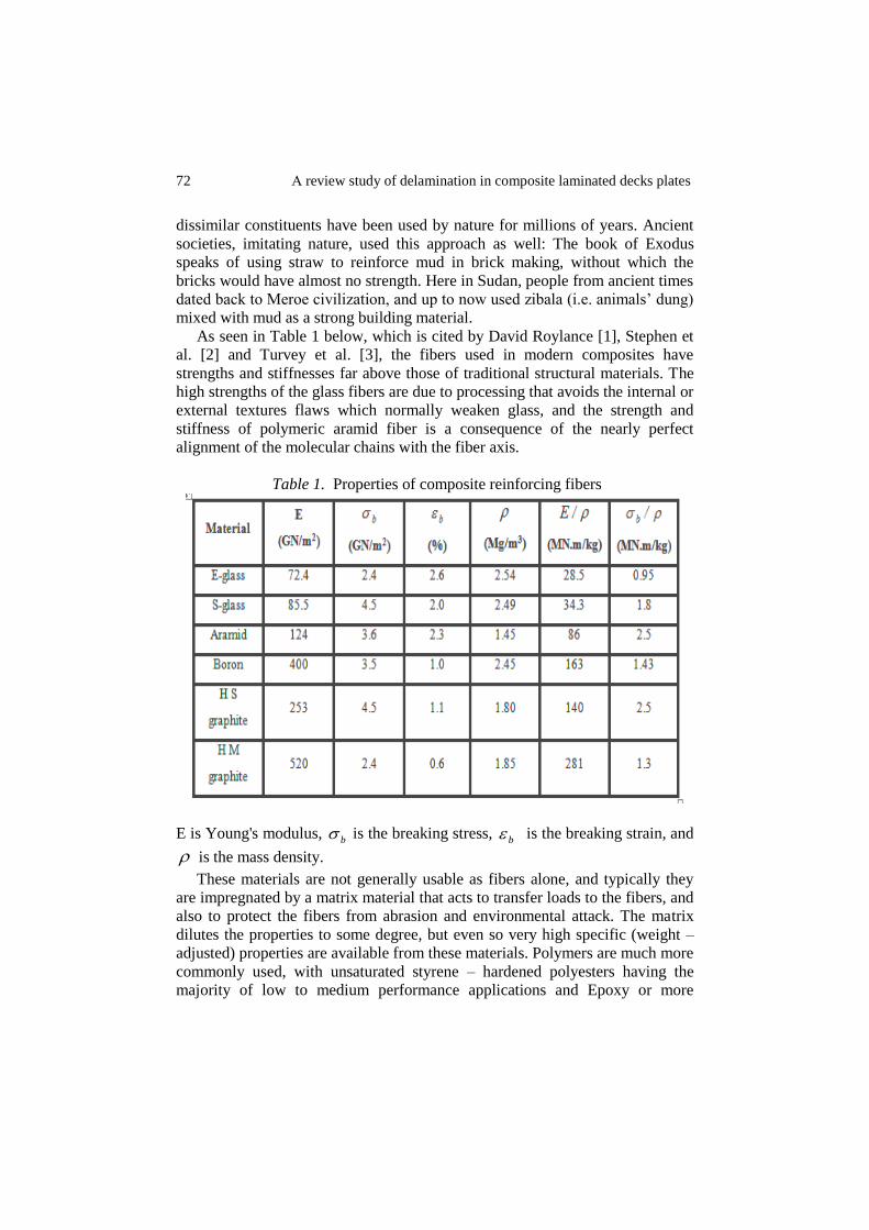
Table 1. Properties of composite reinforcing fibers
E is Young's modulus, b is the breaking stress,
b is the breaking strain, and
is the mass density.
These materials are not generally usable as fibers alone, and typically they
are impregnated by a matrix material that acts to transfer loads to the fibers, and
also to protect the fibers from abrasion and environmental attack. The matrix
dilutes the properties to some degree, but even so very high specific (weight –
adjusted) properties are available from these materials. Polymers are much more
commonly used, with unsaturated styrene – hardened polyesters having the
majority of low to medium performance applications and Epoxy or more
73 idramlE
sophisticated thermosets having the higher end of the market. Thermoplastic
matrix composites are increasingly attractive materials, with processing
difficulties being perhaps their principal limitation.
Recently, composite materials are increasingly used in many mechanical,
civil, and aerospace engineering applications due to two desirable features: the
first one is their high specific stiffness (i.e. stiffness per unit density) and high
specific strength (i.e. strength per unit density), and the second is their
properties that can be tailored through variation of the fiber orientation and
stacking sequence which gives the designers a wide spectrum of flexibility. The
incorporation of high strength, high modulus and low-density filaments in a low
strength and a low modulus matrix material is known to result in a structural
composite material with a high strength to weight ratio. Thus, the potential of a
two-material composite for use in aerospace, under-water, and automotive
structures has stimulated considerable research activities in the theoretical
prediction of the behavior of these materials. One commonly used composite
structure consists of many layers bonded one on top of another to form a high-
strength laminated composite plate. Each lamina is fiber reinforced along a
single direction, with adjacent layers usually having different filament
orientations. For these reasons, composites are continuing to replace other
materials used in structures such as conventional materials. In fact, composites
are the potential structural materials of the future as their cost continues to
decrease due to the continuous improvements in production techniques and the
expanding rate of sales.
1.1 Structure of composites There are many situations in engineering where no single material will be
suitable to meet a particular design requirement. However, two materials in
combination may possess the desired properties and provide a feasible solution
to the materials selection problem. A composite can be defined as a material
that is composed of two or more distinct phases, usually a reinforced material
supported in a compatible matrix, assembled in prescribed amounts to achieve
specific physical and chemical properties.
In order to classify and characterize composite materials, distinction between
the following two types is commonly accepted; see Vernon [4], Jan Stegmann
and Erik Lund [5], and David Roylance [1].
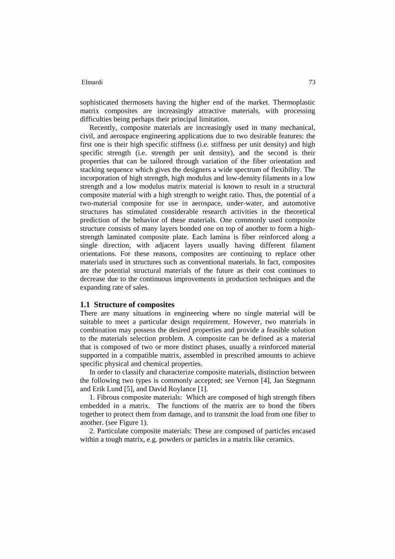
1. Fibrous composite materials: Which are composed of high strength fibers
embedded in a matrix. The functions of the matrix are to bond the fibers
together to protect them from damage, and to transmit the load from one fiber to
another. (see Figure 1).
2. Particulate composite materials: These are composed of particles encased
within a tough matrix, e.g. powders or particles in a matrix like ceramics.
74 Α review study of delamination in composite laminated decks plates
Figure 1. Structure of a fibrous composite
In this study the focus will be on fiber reinforced composite materials, as they
are the basic building element of a rectangular laminated plate structure.
Typically, such a material consists of stacks of bonded-together layers (i.e.
laminas or plies) made from fiber reinforced material. The layers will often be
oriented in different directions to provide specific and directed strengths and
stiffnesses of the laminate. Thus, the strengths and stiffnesses of the laminated
fiber reinforced composite material can be tailored to the specific design
requirements of the structural element being built.
1.2 Mechanical properties of a fiber reinforced lamina Composite materials have many mechanical characteristics, which are different
from those of conventional engineering materials such as metals. More
precisely, composite materials are often both inhomogeneous and non-isotropic.
Therefore, and due to the inherent heterogeneous nature of composite materials,
they can be studied from a micromechanical or a macro mechanical point of
view. In micromechanics, the behavior of the inhomogeneous lamina is defined
in terms of the constituent materials; whereas in macro mechanics the material
is presumed homogeneous and the effects of the constituent materials are
detected only as averaged apparent macroscopic properties of the composite
material. This approach is generally accepted when modeling gross response of
composite structures. The micromechanics approach is more convenient for the
analysis of the composite material because it studies the volumetric percentages
of the constituent materials for the desired lamina stiffnesses and strengths, i.e.
the aim of micromechanics is to determine the moduli of elasticity and strength
of a lamina in terms of the moduli of elasticity, and volumetric percentage of
the fibers and the matrix. To explain further, both the fibers and the matrix are
assumed homogeneous, isotropic and linearly elastic.
Stiffness and Strength of a Lamina
The fibers may be oriented randomly within the material, but it is also
possible to arrange for them to be oriented preferentially in the direction
expected to have the highest stresses. Such a material is said to be anisotropic

75 idramlE
(i.e. different properties in different directions), and control of the anisotropy is
an important means of optimizing the material for specific applications. At a
microscopic level, the properties of these composites are determined by the
orientation and distribution of the fibers, as well as by the properties of the fiber
and matrix materials.
Consider a typical region of material of unit dimensions, containing a
volume fraction, Vf of fibers all oriented in a single direction. The matrix
volume fraction is then, fm VV 1 . This region can be idealized by gathering
all the fibers together, leaving the matrix to occupy the remaining volume. If a
stress l is applied along the fiber direction, the fiber and matrix phases act in
parallel to support the load. In these parallel connections the strains in each
phase must be the same, so the strain l in the fiber direction can be written
as:
mfl (1)
(Where: the subscripts l, f and m denote the lamina, fibers and matrix
respectively).
The forces in each phase must add to balance the total load on the material.
Since the forces in each phase are the phase stresses times the area (here
numerically equal to the volume fraction), we have
mlmflfmmffl VEVEVV (2)
The stiffness in the fiber direction is found by dividing the stress by the strain:
mmff
l
l
l VEVEE
(3)
(Where: E is the longitudinal Young's modulus)
This relation is known as a rule of mixtures prediction of the overall modulus in
terms of the moduli of the constituent phases and their volume fractions.
Rule of mixtures estimates for strength proceed along lines similar to those
for stiffness. For instance, consider a unidirectional reinforced composite that is
strained up to the value at which the fiber begins to fracture. If the matrix is
more ductile than the fibers, then the ultimate tensile strength of the lamina in
equation (2) will be transformed to:
f
f
mf
u
f VV 1 u
l (4)
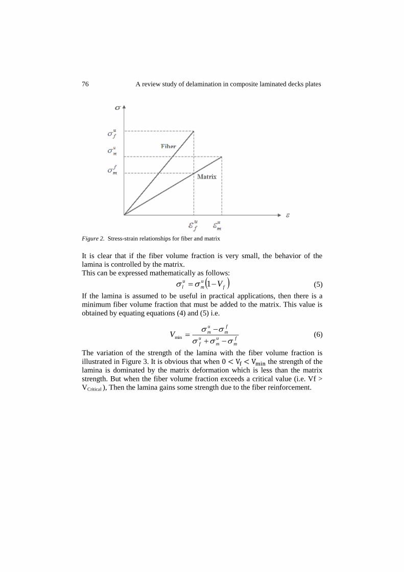
Where the superscript u denotes an ultimate value, and f
m is the matrix stress
when the fibers fracture as shown in Figure 2.
76 Α review study of delamination in composite laminated decks plates
Figure 2. Stress-strain relationships for fiber and matrix
It is clear that if the fiber volume fraction is very small, the behavior of the
lamina is controlled by the matrix.
This can be expressed mathematically as follows:
f
u
m
u
l V 1 (5)
If the lamina is assumed to be useful in practical applications, then there is a
minimum fiber volume fraction that must be added to the matrix. This value is
obtained by equating equations (4) and (5) i.e.
f
m
u
m
u
f
f
m
u
mV
min (6)
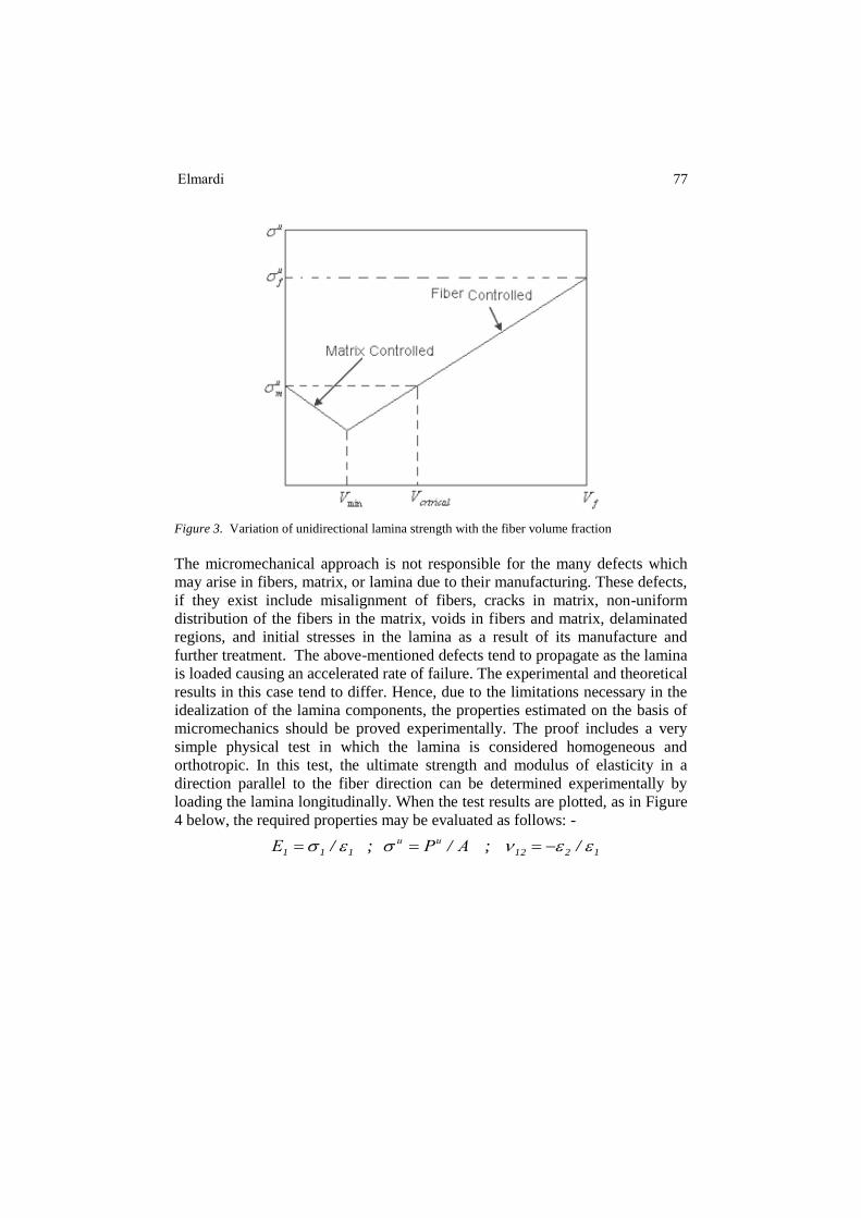
The variation of the strength of the lamina with the fiber volume fraction is
illustrated in Figure 3. It is obvious that when the strength of the
lamina is dominated by the matrix deformation which is less than the matrix
strength. But when the fiber volume fraction exceeds a critical value (i.e. Vf >
VCritical ), Then the lamina gains some strength due to the fiber reinforcement.
77 idramlE
Figure 3. Variation of unidirectional lamina strength with the fiber volume fraction
The micromechanical approach is not responsible for the many defects which
may arise in fibers, matrix, or lamina due to their manufacturing. These defects,
if they exist include misalignment of fibers, cracks in matrix, non-uniform
distribution of the fibers in the matrix, voids in fibers and matrix, delaminated
regions, and initial stresses in the lamina as a result of its manufacture and
further treatment. The above-mentioned defects tend to propagate as the lamina
is loaded causing an accelerated rate of failure. The experimental and theoretical
results in this case tend to differ. Hence, due to the limitations necessary in the
idealization of the lamina components, the properties estimated on the basis of
micromechanics should be proved experimentally. The proof includes a very
simple physical test in which the lamina is considered homogeneous and
orthotropic. In this test, the ultimate strength and modulus of elasticity in a
direction parallel to the fiber direction can be determined experimentally by
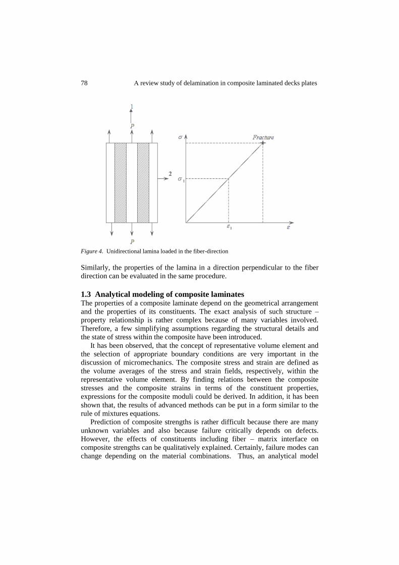
loading the lamina longitudinally. When the test results are plotted, as in Figure
4 below, the required properties may be evaluated as follows: -
1212111 / ; / ; / APE uu
78 Α review study of delamination in composite laminated decks plates
Figure 4. Unidirectional lamina loaded in the fiber-direction
Similarly, the properties of the lamina in a direction perpendicular to the fiber
direction can be evaluated in the same procedure.
1.3 Analytical modeling of composite laminates The properties of a composite laminate depend on the geometrical arrangement
and the properties of its constituents. The exact analysis of such structure –
property relationship is rather complex because of many variables involved.
Therefore, a few simplifying assumptions regarding the structural details and
the state of stress within the composite have been introduced.
It has been observed, that the concept of representative volume element and
the selection of appropriate boundary conditions are very important in the
discussion of micromechanics. The composite stress and strain are defined as
the volume averages of the stress and strain fields, respectively, within the
representative volume element. By finding relations between the composite
stresses and the composite strains in terms of the constituent properties,
expressions for the composite moduli could be derived. In addition, it has been
shown that, the results of advanced methods can be put in a form similar to the
rule of mixtures equations.
Prediction of composite strengths is rather difficult because there are many
unknown variables and also because failure critically depends on defects.
However, the effects of constituents including fiber – matrix interface on
composite strengths can be qualitatively explained. Certainly, failure modes can
change depending on the material combinations. Thus, an analytical model
79 idramlE
developed for one material combination cannot be expected to work for a
different one. Ideally a truly analytical model will be applicable to material
combination. However, such an analytical model is not available at present.
Therefore, it has been chosen to provide models each of which is applicable
only to a known failure mode. Yet, they can explain many of the effects of the
constituents. (Refer to Ref. [2]).
2 LITERATURE REVIEW Delamination is important phenomenon damage in the laminated composite
materials due to weakness of reinforcement through the thickness. The study of
the delamination of a laminate may be performed using an approach of fracture
mechanics or by introducing appropriate constitutive laws of the interface
between the layers constituting the laminate. From a physical point of view, it is
reasonable to assume that the second approach can be related to fracture
mechanics. In fact, when decohesion occurs between adjacent layers, there is
evolution of delaminated surface which is equivalent to the propagation of a
crack in a direction a priori known. The literature dealing with the phenomenon
of delamination is very large. A presentation of several structures subjected to
the phenomenon of delamination, can be found in [6] and [7].
The delamination phenomenon can be caused by concentration of
interlaminar stresses that occur in the vicinity of the free edges or in around of
the holes in laminated plates [8]. In addition, the interlaminar defects can grow
under a compressive loading. In this case the thin laminated layers degrade
(deboning interfaces) and are responsible for increased stresses in the vicinity of
the boundaries of delaminated surfaces. In the analysis of the delamination can
be distinguished the stage of the crack initiation from the phase of the crack
propagation. For prediction of the initiation of a crack from a free edge, the
technical Cal culations of the effect of the edge of elasticity [9] and [10], related
to criteria based on the average of the normal stresses on a characteristic
distance from the edge of the structure [11] are usually used in post- processor
of an elastic design in laminated structures.
Delamination does not occur necessarily where the stresses are highest. In
the phase of the propagation of a delamination established, approaches based on
the linear fracture mechanics are generally used. The rate of energy release G is
a parameter that is often used to describe the behavior of the phenomenon of
delamination in composite materials and structures. G is defined as the energy
released from the newly fractured surface and compared to the critical value Gc
(This method is used by many authors for the study of crack propagation [12]
and [13], but not treat the problem of the initiation of a delamination crack. In
contrary the approach of the damage mechanics of the composite can describe
the initiation of delamination. The rate of energy release is calculated from the
forces and nodal displacements [14] and [15]. The state equations and the
80 Α review study of delamination in composite laminated decks plates
evolution laws of the interface provided in the context of thermodynamics are
described in [16] – [22]. Models of elastic and damageable interface are
presented in [23] – [27] and generalized in [28]. In these models, special
interface elements are applied in areas where the delamination phenomenon is
likely to occur. Elements plane strain with cubic interpolation functions were
introduced for discretization of the laminate ply [29]. Other models have been
developed for modeling damage layer [30] and interface phenomena [31]. These
models are based on the damage mechanics. The interface is considered as a
three-dimensional medium with negligible thickness compared to the other
dimensions. Therefore, the interface can be considered as two-dimensional
entity witch transfers traction and displacement from one layer to the other [32].
The interface is assumed to be dependent on the fiber orientation of adjacent
layers and it is assumed to be elastic and damageable. Delamination may be
caused by interlaminar stress [9]. The objective of this paper is to present a
method to simulate progressive delamination based on a new mixed-mode
failure criterion in the context of damage mechanics. This study will highlight
the positive contribution of the powder core dates incorporated in the new
woven composite. The date cores powder incorporation has an increase effect of
the mechanical characteristics giving to the hybrid composite a better behavior
and reducing certain types of degradation like delamination.
It is important to recognize that, with the advent of composite media, certain
new material imperfections can be found in composite structures in addition to
the better – known imperfections that one finds in metallic structures. Thus,
broken fibers, delaminated regions, cracks in the matrix material, as well as
holes, foreign inclusions and small voids constitute material and structural
imperfections that can exist in composite structures. Imperfections have always
existed and their effect on the structural response of a system has been very
significant in many cases. These imperfections can be classified into two broad
categories: initial geometrical imperfections and material or constructional
imperfections.
The first category includes geometrical imperfections in the structural
configuration (such as a local out of roundness of a circular cylindrical shell,
which makes the cylindrical shell non – circular; a small initial curvature in a
flat plate or rod, which makes the structure non – flat, etc.), as well as
imperfections in the loading mechanisms (such as load eccentricities; an axially
loaded column is loaded at one end in such a manner that a bending moment
exists at that end). The effect of these imperfections on the response of
structural systems has been investigated by many researchers and the result of
these efforts can be easily found in books [3], as well as in published papers
[33] – [50].
The second class of imperfections is equally important, but has not received
as much attentions as the first class; especially as far as its effect on the
buckling response characteristics is concerned. For metallic materials, one can
81 idramlE
find several studies which deal with the effect of material imperfections on the
fatigue life of the structural component. Moreover, there exist a number of
investigations that deal with the effect of cut – outs and holes on the stress and
deformation response of thin plates. Another material imperfection is the rigid
inclusion. The effect of rigid inclusions on the stress field of the medium in the
neighborhood of the inclusion has received limited attention. The interested
reader is referred to the bibliography of Professor Naruoka [33].
There exist two important classes of material and constructional – type
imperfections, which are very important in the safe design, especially of aircraft
and spacecraft. These classes consist of fatigue cracks or cracks in general and
delamination in systems that employ laminates (i.e. fiber – reinforced
composites). There is considerable work in the area of stress concentration at
crack tips and crack propagation. Very few investigations are cited, herein, for
the sake of brevity. These include primarily those dealing with plates and shells
and non – isotropic construction. Some deal with cracks in metallic plates and
shells [51] – [54]. Others deal with non – isotropic construction and investigate
the effects of non – isotropy [55] – [60]. In all of these studies, there is no
mention of the effect of the crack presence on the overall stability or instability
of the system.
Finally, delamination is one of the most commonly found defects in
laminated structural components. Most of the work found in the literature deals
with flat configurations.
Composite structures often contain delamination. Causes of delamination are
many and include tool drops, bird strikes, runway debris hits and manufacturing
defects. Moreover, in some cases, especially in the vicinity of holes or close to
edges in general, delamination starts because of the development of interlaminar
stresses. Several analyses have been reported on the subject of edge
delamination and its importance in the design of laminated structures. A few of
these works are cited [61] – [67]. These and their cited references form a good
basis for the interested reader. The type of delamination that comprises the basic
and primary treatise is the one that is found to be present away from the edges
(internal). This delaminating could be present before the laminate is loaded or it
could develop after loading because of foreign body (birds, micrometer, and
debris) impact. This is an extremely important problem especially for laminated
structures that are subject to destabilizing loads (loads that can induce instability
in the structure and possibly cause growth of the delamination; both of these
phenomena contribute to failure of the laminate). The presence of delamination
in these situations may cause local buckling and / or trigger global buckling and
therefore induce a reduction in the overall load – bearing capacity of the
laminated structure. The problem, because of its importance, has received
considerable attention.
82 Α review study of delamination in composite laminated decks plates
3 CONCLUSIONS Delamination is a critical failure mode in fiber-reinforced composite decks
plates and beams. It may lead directly to through-thickness failure owing to
interlaminar stresses caused by out of plane loading, curved or tapered
geometry, or discontinuities owing to cracks, ply drops or free edges. Impact
loading causes multiple delaminations, which can propagate in conjunction with
sub laminate buckling, greatly reducing the residual compressive strength.
ACKNOWLEDGMENTS The authors would like to acknowledge with deep thanks and profound
gratitude Mr. Osama Mahmoud of Daniya Center for Publishing and Printing
Services, Atbara, Sudan who spent many hours in editing, re – editing of the
manuscript in compliance with the standard format of International Journal of
Bridge Engineering (IJBE).
4 REFERENCES [1] David Roylance, 'An introduction to composite materials', Department of material science and
engineering, Massachusetts Institute of Technology, Cambridge; (2000).
[2] Stephen W. Tsai, Thomas Hahn H., 'Introduction to composite materials', Technomic
publishing company; (1980).
[3] Turvey G.J., Marshall I.H., 'Buckling and post buckling of composite plates', Great Britain,
T.J. press Ltd, Padstow, Cornwall; (1995).
[4] Vernon B. John, 'Introduction to engineering materials', second edition; (1972).
[5] Jan Stegmann and Erik Lund, ' notes on structural analysis of composite shell structures',
Aalborg University, Denmark; (2001).
[6] A. C. Garg, A damage model in composite structures, Engineering Fracture Mech., 1998. vol.
29.
[7] O. O. Ochoa. and Reddy J.N, Finite elements analysis of composites laminates, Kluwer, 1992.
[8] S. Jain and D.C.H. Yang, Effects of federate and chisel edge on delamination in composite
drilling. Processing and Manufacturing of Composite Materials, ASME PED 49. 1991. Vol.
27.
[9] D. Engrand, Boundary layer approach to the Calculation of Transverse stresses along the Free
Edge of a Symmetric Laminated Plate of Arbitrary Width under in Plane Loading,
Composites Structures, 1981.
[10] H. Dumontet., Study of Boundary layer Problem in Elastic composite Materials, M2AN, 20,
1986.
[11] R. Y. Kim. and S.R. Sony, Delamination of Composite Laminates Stimulated by interlaminar
Shear, ASTM-STP 893, 1986.
[12] A.S.D. Wang, M. Slomania. and R.B. Bucinell, Delamination Crack Growth in Composite
Laminates. Delamination and Debonding of Materials, JOHNSON W.S (Ed.), ASTMSTP,
1985.
[13] A.S.D. WANG, Fracture Analysis of Interlaminar cracking, Interlaminar response of
Composite Materials, Composite materials Series, PAGANO N.J. (Ed.) Elsevier, 1989.
[14] D.B. Davidson., R. Kruger and M. König. Effect of stacking sequence on energy release rate
distribution in multi-directional DCB and ENF specimens. Engineering Fracture Mech.,
1996. vol. 55-4.
83 idramlE
[15] T. K. O'Brien, Mixed-mode strain-energy-release rate effects on edge delamination of
composites, In: damage in composite Materials, ASTM STP 836, ASTM, Philadelphia, PA,
1984.
[16] M. Fremond. Adherence des solides,J. Mécan. Théor. Appl. 6,1987.
[17] M. Fremond. Contact with Adhesion. In Topic in Non-smooth Mechanics, Birkhäuser, 1988.
[18] N. Point, Approche Mathématiques de problèmes à frontières libres: Application à des
exemples physiques, Thèse de doctorat d’Etat Es-Sciences Mathématiques de l’Université
Paris XIII, 1989.
[19] J. M. Truong Dinh Tien, Contact avec adhérence. Thèse de Doctorat de l’Université Paris VI,
1990.
[20] L. Ascione and D. Bruno On delamination problem of two layer plates. In unilateral
problems in Structural Analysis, Springer, Berlin, 1985.
[21] A. Girmaldi and J.N. Reddy On delamination in plates: a unilateral contact approach. In
Unilateral Problems in Structural Analysis, Springer, Berlin, 1985.
[22] P. Ladevèze. A damage computational method for composite structures. Computer
Structures, (1992). vol. 44.
[23] O. Allix.and P.Ladevèze, Interlaminar interface modeling for the prediction of delamination,
Composites Structures, 1992.
[24] A. Corigliano, Formulation identification and use of interface models in the numerical
analysis of composite delamination, Int. J. Solids Structures, 1993. vol. 30.
[25] J. C. Schellekens and DE R. Borst, Free edge delamination in carbon epoxy laminates: A
novel numerical/experimental approach, Composites Structures, 1993. vol. 28.
[26] Leandro José da Silva1, TúlioHallak Panzera, André Luis Christoforo, Luís Miguel Pereira
Durão, Francisco Antonio Rocco Lahr, Numerical and Experimental Analyses of Bio
composites Reinforced with Natural Fibers, International Journal of Materials Engineering
2012, 2(4): 43-49
[27] D. Benzerga, A. Haddi., ASeddak. and ALavie, Mixed-mode damage model for delamination
growth applied to a new woven composite, Computational Materials Science, 2008. vol. 41,
pp. 515–521
[28] P. Ladevèze and E. Ledantec, Damage modeling of the elementary ply for laminated
composites, Composites Sciences and technology, 1992. vol. 43.
[29] O. Alix and P. Ladevèze, Interlaminar Interface modeling for Prediction of Delamination,
Composites Structures, 1992. vol. 22.
[30] F. Gruttmann and W. Wagner, On the numerical analysis of local effects, Composites
structures, 1994. vol. 29.
[31] J. C. Simo and M. S. Rifai. A, class of mixed assumed strain methods and the method of
incompatible modes, Int. Num. Meth. Eng, 1990. vol. 29.
[32] P. P. Camanho, C. G. Dàvila and D.R Ambur, Numerical Simulation of Delamination
Growth in Composite Materials. NASA/TP -211041, 2001.
[33] Naruoka M., 'Bibliography on theory of plates', Gihodo, Tokyo; (1981).
[34] Winterstetter Th. A. and Schmidt H., 'Stability of circular cylindrical steel shells under
combined loading', Thin – walled structures; (2002), 40: PP. (893 –909).
[35] Pircher M., and Bridge R., 'The influence of circumferential weld-induced imperfections on
the buckling of silos and tanks', Journal of constructional steel research; (2001), 57 (5): PP.
(569 – 580).
[36] Deml M., and Wunderlich W., 'Direct evaluation of the worst imperfection shape in shell
buckling', Computer methods in applied mechanics and engineering; (1997), 149 [1 – 4]: PP.
(201 – 222).
[37] Arbocz J., and Starnes J.H.,' Future directions and challenges in shell stability analysis', Thin
– walled structures; (2002), 40: PP. (729 – 754).
84 Α review study of delamination in composite laminated decks plates
[38] Arbocz J.,'The effect of imperfect boundary conditions on the collapse behavior of
anisotropic shells', International Journal of solids and structures; (2000), 37: PP. (6891 –
6915).
[39] Huhne C., Zimmermann R., Rolfes R., and Geier B., 'Loading imperfections – experiments
and Computations', Euromech Colloquium 424 ;( 2001), the Netherlands.
[40] Geier B., Klein H., and Zimmermann R., 'Buckling tests with axially Compressed unstiffened
cylindrical shells made from CFRP', proceedings, International Colloquium on buckling of
shell structures on land, in the sea, and in the air, Elsevier applied sciences; (1991), London
and New York: PP. (498– 507).
[41] Geier B., Klein H., and Zimmermann,' Experiments on buckling of CFRP Cylindrical shells
under non-uniform axial load', proceedings of international conference on Composites
engineering; (1994).
[42] Albus J., Gomez-Garcia J., and Οery H., 'Control of assembly induced stresses and
deformations due to the waviness of the interface flanges of the ESC – An upper stage', 52nd
International astronautical congress; (2001), Toulouse, France.
[43] Zimmermann R., 'Buckling research for imperfection tolerant fiber composite structures',
proceeding of the conference on spacecraft structures, material and mechanical testing,
Nordwijk, The Netherlands: (1996).
[44] Meyer-Piening H.R., Farshad M., Geier B., and Zimmermann, 'Buckling loads of CFRP
Composite cylinders under combined axial and torsion loading – experiments and
computations', Composite structures; (2001), 52: PP. (427 – 435).
[45] CMH-17 (Composite Material Handbook-17), Material science corporation; (2010).
[46] Guo S.J., 'Stress concentration and buckling behaviour of shear loaded composite panels with
reinforced cutouts', Composite structures; (2007): PP. (1– 9).
[47] Remmers J.J.C., and de Borst R., 'Delamination buckling of fiber-metal laminates',
Composite science and technology; (2001): PP. (2207 – 2213).
[48] Vit obdrzalek, and Jan Vrbka, 'Buckling and post buckling of a large delaminated plate
subjected to shear loading', Engineering mechanics, vol. 16; (2009), No.4: PP. (297 – 312).
[49] Vit obdrzalek, and Jan Vrbka,' On buckling of a plate with multiple delaminations',
Engineering mechanics, vol.17; (2010), No. 1: PP. (37 – 47).
[50] Keiichi Nemoto, Hirakazu Kasuya, Hisao Kikugawa, and Takashi Asaka,' post buckling
behavior of composite laminated plates with initial imperfections under biaxial compression',
Materials transactions, vol.50, No.2;(2009): PP. (299 – 304).
[51] Takao Y., Taya M., and Chou T.W.,' Stress field due to cylindrical inclusion with constant
axial Eigen strain in an infinite elastic body', Journal of applied mechanics; (1981), 48(4):
PP. (853 – 858).
[52] Lakshminarayana H.V., and Murthy M.V.V.,' On stresses around an arbitrarily oriented
Crack in cylindrical shell', International Journal of fracture; (1976), 12(4): PP. (547 – 566).
[53] Twee J., and Rooke D.P,' The stress intensity factor for a crack at the edge of a loaded hole',
International Journal of solids and structures; (1979), 15: PP. (899 – 906).
[54] Dyshel M.S., 'Fracture of plates with cracks under tension after loss of stability', Journal of
applied mathematics and mechanics (PMM); (1981), 17(4): PP. (77 – 83).
[55] Erdogan F., Ratwani M., and Yuceoglu U., 'On the effect of orthotropy in cracked cylindrical
plates', International Journal of fracture; (1974), 10 (4): PP. (369 – 374).
[56] Krenk S., 'Influence of transverse shear on an axial crack in a cylindrical shell', International
Journal of fracture; (1978), 14(2): PP. (123 – 142).
[57] Delale F., and Erdogan F., 'Effect of transverse shear and material orthotropy in a cracked
spherical cap', International Journal of solids and structures; (1979), 15: PP. (907 – 926).
[58] Lakshminarayana H.V., and Murthy M.V.V, 'On a finite element model for the analysis of
through cracks in laminated anisotropic cylindrical shells', Engineering fracture mechanics;
(1981), 14(4): PP. (697 – 712).
85 idramlE
[59] Theocaris P.S., and Milios J., 'Crack-arrest at a bimaterial interface', International Journal of
solids and structures; (1981), 17: PP. (217 – 230).
[60] Rogers T.G., 'Crack extension and energy release rates in finitely deformed sheet reinforced
with inextensible fibers', International Journal of solids and structures; (1982), 18: PP. (705 –
721).
[61] Kachanov L.M., 'Separation failure of composite materials', polymer mechanics; (1976), 6
(12): PP. (812 – 815).
[62] Williams J.G., and et al., 'Recent developments in the design, testing and impact damage –
tolerance of stiffened composite plates', Nasa TM 80077; (1979), April.
[63] Wilkins D.J, and et al., 'Characterizing delamination growth in graphite-epoxy', Damage in
composite materials; (1982): PP. (168 – 183).
[64] Wang S.S., 'Edge delamination in angle-ply composite laminates', AIAA Journal; (1984),
22(2): PP. (256 – 264).
[65] Scott W. Beckwith, 'Manufacturing defects in composite structures', Sample Journal, volume
48, No.5; September/October (2012).
[66] M. Vable, 'Stability of columns', Mechanics of materials; (2014): chapter eleven: PP. (496 –
528).
[67] CPNI EBP, 'Influence of delamination of laminated glass on its blast performance', July
(2013).