Embed Size (px)
Citation preview
A Sample Program
This lecture will focus on a sample program that was assigned for all studentsto execute on the mainframe. This program is run under the IBM operatingsystem called OS (as opposed to DOS), which is tailored for large installations.
Please note that the IBM mainframe operating system DOS is not related to thatonce used on small computers. The latter, often called “DOS” is really MSDOS,the Microsoft Disk Operating System.
This lecture contains both code fragments and annotations on those code fragments.Code fragments will be presented in the font Courier New (bold), as follows.
SAVE (14,12)
All other material will be in the standard font Times New Roman, as is this sentence.
The student will recall that the input to the assembler is not free–form; column placementis extremely important. Your instructor discovered this fact when an otherwise correctprogram would not assembly correctly.
Column Conventions in the Assembler Program
The column conventions are as follows:
Columns 1 – 8 The name or label of the statement or declarative
Column 9 This must be blank
Columns 10 – 14 The operation: instruction, declarative, or macro
Column 15 This must be blank
Columns 16 – 71 The operands for the operation.Any continuation line must begin in column 16.
Column 72 If nonblank, the next line is a continuation of this one.
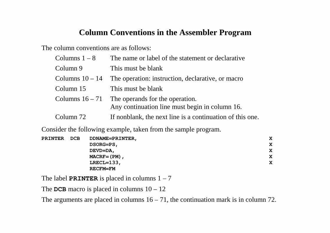
Consider the following example, taken from the sample program.PRINTER DCB DDNAME=PRINTER, X
DSORG=PS, XDEVD=DA, XMACRF=(PM), XLRECL=133, XRECFM=FM
The label PRINTER is placed in columns 1 – 7
The DCB macro is placed in columns 10 – 12
The arguments are placed in columns 16 – 71, the continuation mark is in column 72.
More on Column Conventions
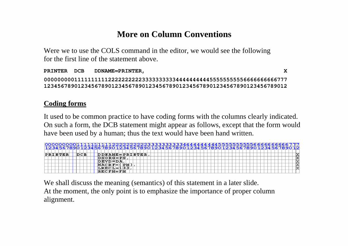
Were we to use the COLS command in the editor, we would see the followingfor the first line of the statement above.
PRINTER DCB DDNAME=PRINTER, X
000000000111111111122222222223333333333444444444455555555556666666666777123456789012345678901234567890123456789012345678901234567890123456789012
Coding forms
It used to be common practice to have coding forms with the columns clearly indicated.On such a form, the DCB statement might appear as follows, except that the form wouldhave been used by a human; thus the text would have been hand written.
We shall discuss the meaning (semantics) of this statement in a later slide.At the moment, the only point is to emphasize the importance of proper columnalignment.
Column 1
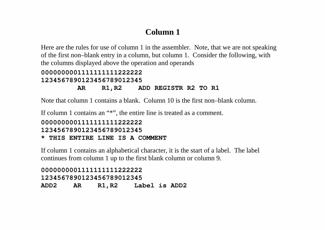
Here are the rules for use of column 1 in the assembler. Note, that we are not speakingof the first non–blank entry in a column, but column 1. Consider the following, withthe columns displayed above the operation and operands
00000000011111111112222221234567890123456789012345
AR R1,R2 ADD REGISTR R2 TO R1
Note that column 1 contains a blank. Column 10 is the first non–blank column.
If column 1 contains an “*”, the entire line is treated as a comment.
00000000011111111112222221234567890123456789012345* THIS ENTIRE LINE IS A COMMENT
If column 1 contains an alphabetical character, it is the start of a label. The labelcontinues from column 1 up to the first blank column or column 9.
00000000011111111112222221234567890123456789012345ADD2 AR R1,R2 Label is ADD2
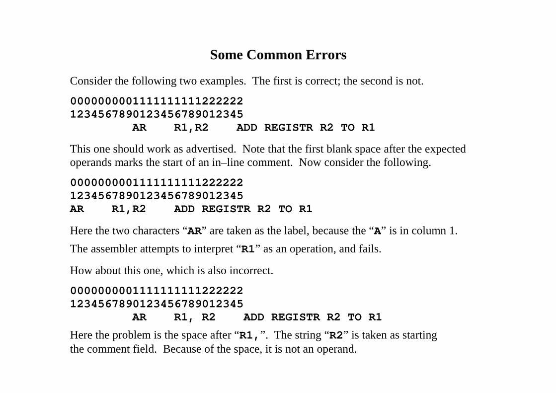
Some Common Errors
Consider the following two examples. The first is correct; the second is not.
00000000011111111112222221234567890123456789012345
AR R1,R2 ADD REGISTR R2 TO R1
This one should work as advertised. Note that the first blank space after the expectedoperands marks the start of an in–line comment. Now consider the following.
00000000011111111112222221234567890123456789012345AR R1,R2 ADD REGISTR R2 TO R1
Here the two characters “AR” are taken as the label, because the “A” is in column 1.
The assembler attempts to interpret “R1” as an operation, and fails.
How about this one, which is also incorrect.
00000000011111111112222221234567890123456789012345
AR R1, R2 ADD REGISTR R2 TO R1
Here the problem is the space after “R1,”. The string “R2” is taken as startingthe comment field. Because of the space, it is not an operand.
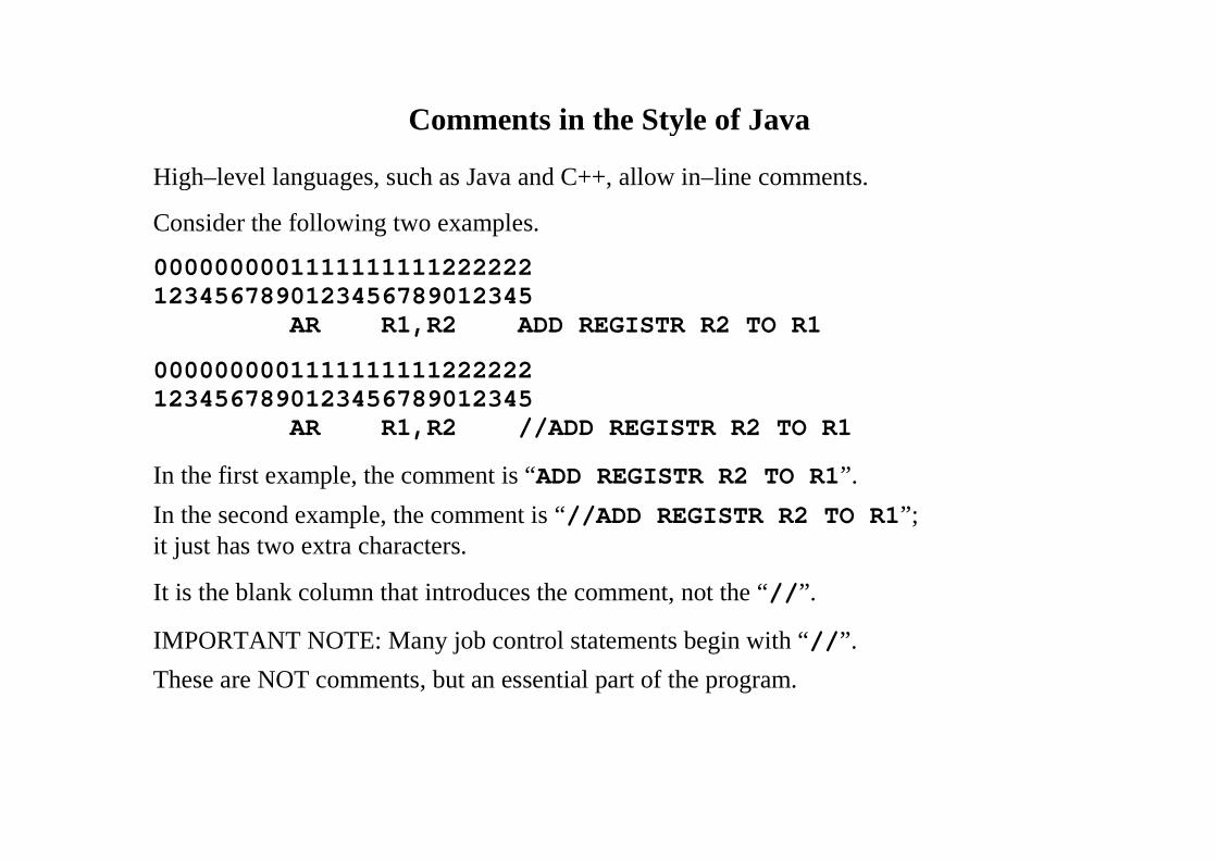
Comments in the Style of Java
High–level languages, such as Java and C++, allow in–line comments.
Consider the following two examples.
00000000011111111112222221234567890123456789012345
AR R1,R2 ADD REGISTR R2 TO R1
00000000011111111112222221234567890123456789012345
AR R1,R2 //ADD REGISTR R2 TO R1
In the first example, the comment is “ADD REGISTR R2 TO R1”.
In the second example, the comment is “//ADD REGISTR R2 TO R1”;it just has two extra characters.
It is the blank column that introduces the comment, not the “//”.
IMPORTANT NOTE: Many job control statements begin with “//”.
These are NOT comments, but an essential part of the program.
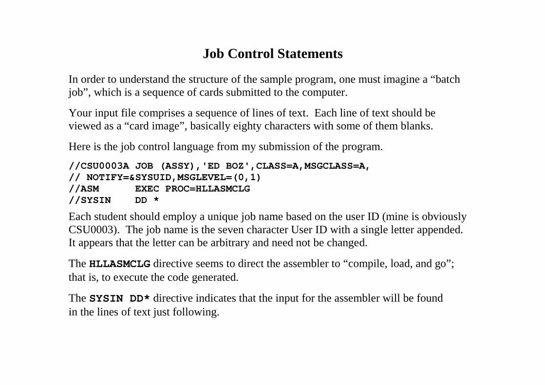
Job Control Statements
In order to understand the structure of the sample program, one must imagine a “batchjob”, which is a sequence of cards submitted to the computer.
Your input file comprises a sequence of lines of text. Each line of text should beviewed as a “card image”, basically eighty characters with some of them blanks.
Here is the job control language from my submission of the program.
//CSU0003A JOB (ASSY),'ED BOZ',CLASS=A,MSGCLASS=A,// NOTIFY=&SYSUID,MSGLEVEL=(0,1)//ASM EXEC PROC=HLLASMCLG//SYSIN DD *
Each student should employ a unique job name based on the user ID (mine is obviouslyCSU0003). The job name is the seven character User ID with a single letter appended.It appears that the letter can be arbitrary and need not be changed.
The HLLASMCLG directive seems to direct the assembler to “compile, load, and go”;that is, to execute the code generated.
The SYSIN DD* directive indicates that the input for the assembler will be foundin the lines of text just following.
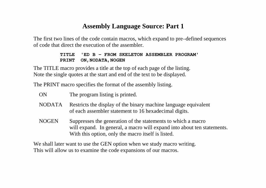
Assembly Language Source: Part 1
The first two lines of the code contain macros, which expand to pre–defined sequencesof code that direct the execution of the assembler.
TITLE 'ED B - FROM SKELETON ASSEMBLER PROGRAM'PRINT ON,NODATA,NOGEN
The TITLE macro provides a title at the top of each page of the listing.Note the single quotes at the start and end of the text to be displayed.
The PRINT macro specifies the format of the assembly listing.
ON The program listing is printed.
NODATA Restricts the display of the binary machine language equivalentof each assembler statement to 16 hexadecimal digits.
NOGEN Suppresses the generation of the statements to which a macrowill expand. In general, a macro will expand into about ten statements.With this option, only the macro itself is listed.
We shall later want to use the GEN option when we study macro writing.This will allow us to examine the code expansions of our macros.
Assembly Language Source: Part 2
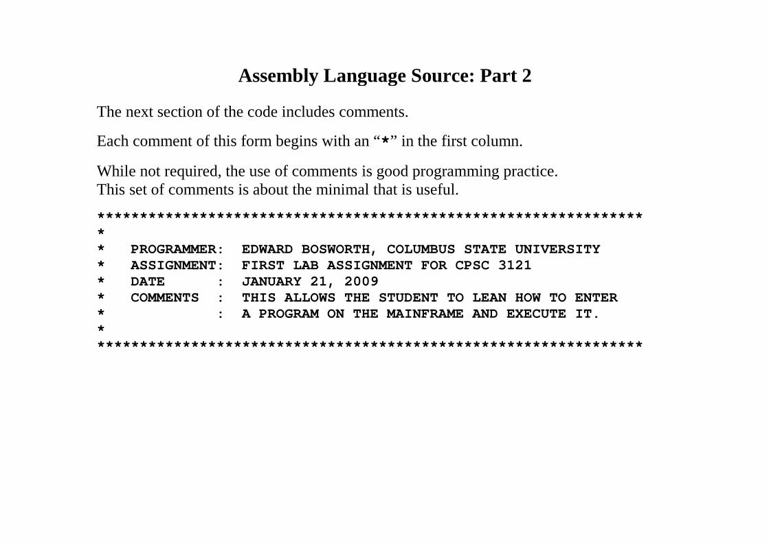
The next section of the code includes comments.
Each comment of this form begins with an “*” in the first column.
While not required, the use of comments is good programming practice.This set of comments is about the minimal that is useful.
****************************************************************** PROGRAMMER: EDWARD BOSWORTH, COLUMBUS STATE UNIVERSITY* ASSIGNMENT: FIRST LAB ASSIGNMENT FOR CPSC 3121* DATE : JANUARY 21, 2009* COMMENTS : THIS ALLOWS THE STUDENT TO LEAN HOW TO ENTER* : A PROGRAM ON THE MAINFRAME AND EXECUTE IT.*****************************************************************
Assembly Language Source: Part 3
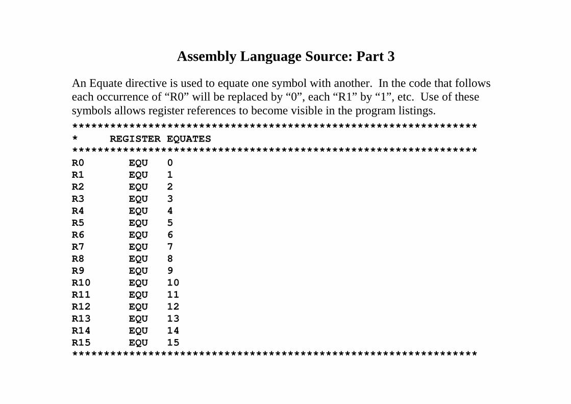
An Equate directive is used to equate one symbol with another. In the code that followseach occurrence of “R0” will be replaced by “0”, each “R1” by “1”, etc. Use of thesesymbols allows register references to become visible in the program listings.
***************************************************************** REGISTER EQUATES****************************************************************R0 EQU 0R1 EQU 1R2 EQU 2R3 EQU 3R4 EQU 4R5 EQU 5R6 EQU 6R7 EQU 7R8 EQU 8R9 EQU 9R10 EQU 10R11 EQU 11R12 EQU 12R13 EQU 13R14 EQU 14R15 EQU 15****************************************************************
Assembly Language Source: Part 4
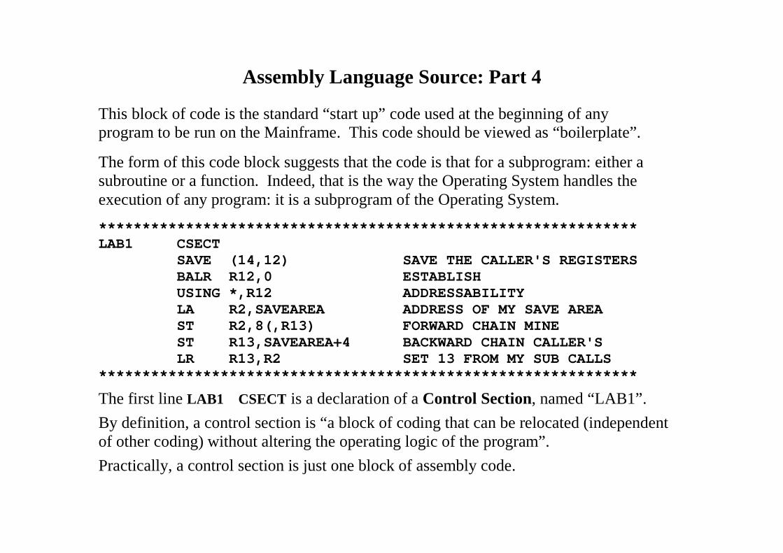
This block of code is the standard “start up” code used at the beginning of anyprogram to be run on the Mainframe. This code should be viewed as “boilerplate”.
The form of this code block suggests that the code is that for a subprogram: either asubroutine or a function. Indeed, that is the way the Operating System handles theexecution of any program: it is a subprogram of the Operating System.
**************************************************************LAB1 CSECT
SAVE (14,12) SAVE THE CALLER'S REGISTERSBALR R12,0 ESTABLISHUSING *,R12 ADDRESSABILITYLA R2,SAVEAREA ADDRESS OF MY SAVE AREAST R2,8(,R13) FORWARD CHAIN MINEST R13,SAVEAREA+4 BACKWARD CHAIN CALLER'SLR R13,R2 SET 13 FROM MY SUB CALLS
**************************************************************
The first line LAB1 CSECT is a declaration of a Control Section, named “LAB1”.
By definition, a control section is “a block of coding that can be relocated (independentof other coding) without altering the operating logic of the program”.
Practically, a control section is just one block of assembly code.
Opening the Input and Output
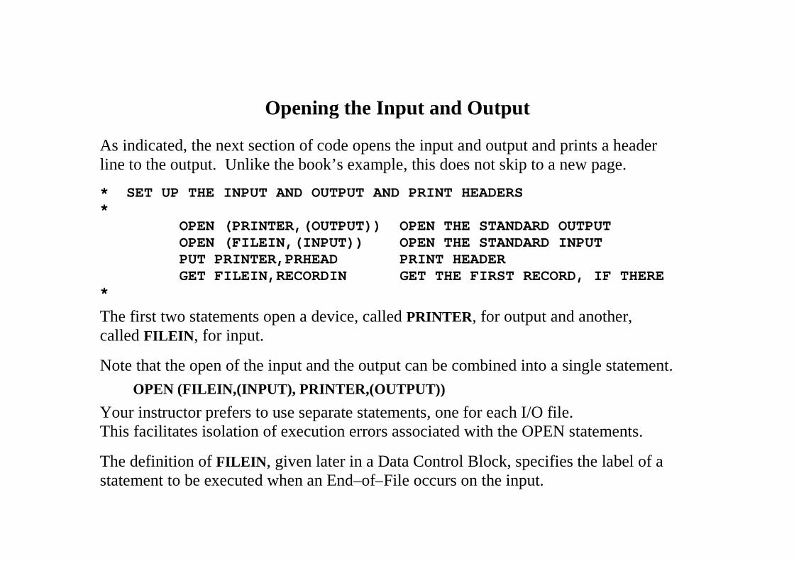
As indicated, the next section of code opens the input and output and prints a headerline to the output. Unlike the book’s example, this does not skip to a new page.
* SET UP THE INPUT AND OUTPUT AND PRINT HEADERS*
OPEN (PRINTER,(OUTPUT)) OPEN THE STANDARD OUTPUTOPEN (FILEIN,(INPUT)) OPEN THE STANDARD INPUTPUT PRINTER,PRHEAD PRINT HEADERGET FILEIN,RECORDIN GET THE FIRST RECORD, IF THERE
*
The first two statements open a device, called PRINTER, for output and another,called FILEIN, for input.
Note that the open of the input and the output can be combined into a single statement.
OPEN (FILEIN,(INPUT), PRINTER,(OUTPUT))
Your instructor prefers to use separate statements, one for each I/O file.This facilitates isolation of execution errors associated with the OPEN statements.
The definition of FILEIN, given later in a Data Control Block, specifies the label of astatement to be executed when an End–of–File occurs on the input.
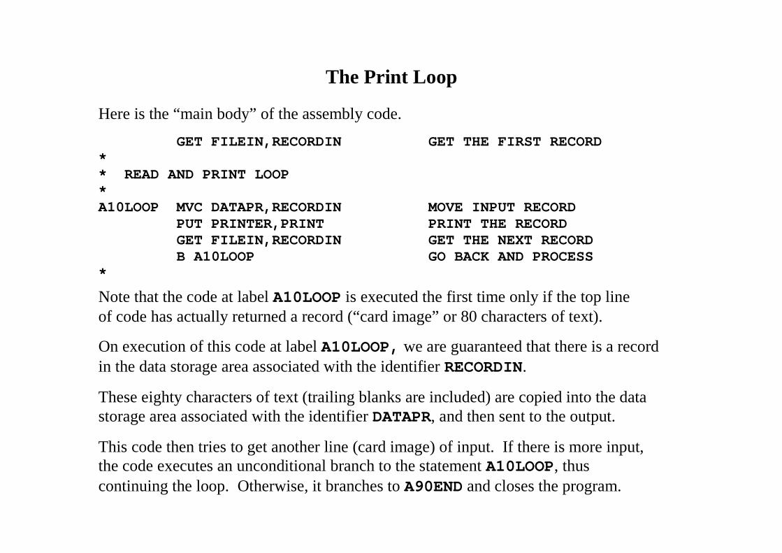
The Print Loop
Here is the “main body” of the assembly code.
GET FILEIN,RECORDIN GET THE FIRST RECORD** READ AND PRINT LOOP*A10LOOP MVC DATAPR,RECORDIN MOVE INPUT RECORD
PUT PRINTER,PRINT PRINT THE RECORDGET FILEIN,RECORDIN GET THE NEXT RECORDB A10LOOP GO BACK AND PROCESS
*
Note that the code at label A10LOOP is executed the first time only if the top lineof code has actually returned a record (“card image” or 80 characters of text).
On execution of this code at label A10LOOP, we are guaranteed that there is a recordin the data storage area associated with the identifier RECORDIN.
These eighty characters of text (trailing blanks are included) are copied into the datastorage area associated with the identifier DATAPR, and then sent to the output.
This code then tries to get another line (card image) of input. If there is more input,the code executes an unconditional branch to the statement A10LOOP, thuscontinuing the loop. Otherwise, it branches to A90END and closes the program.
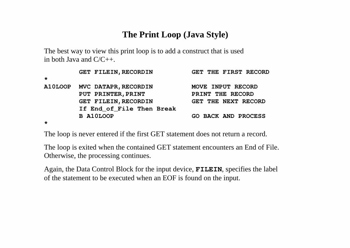
The Print Loop (Java Style)
The best way to view this print loop is to add a construct that is usedin both Java and C/C++.
GET FILEIN,RECORDIN GET THE FIRST RECORD*A10LOOP MVC DATAPR,RECORDIN MOVE INPUT RECORD
PUT PRINTER,PRINT PRINT THE RECORDGET FILEIN,RECORDIN GET THE NEXT RECORDIf End_of_File Then BreakB A10LOOP GO BACK AND PROCESS
*
The loop is never entered if the first GET statement does not return a record.
The loop is exited when the contained GET statement encounters an End of File.Otherwise, the processing continues.
Again, the Data Control Block for the input device, FILEIN, specifies the labelof the statement to be executed when an EOF is found on the input.
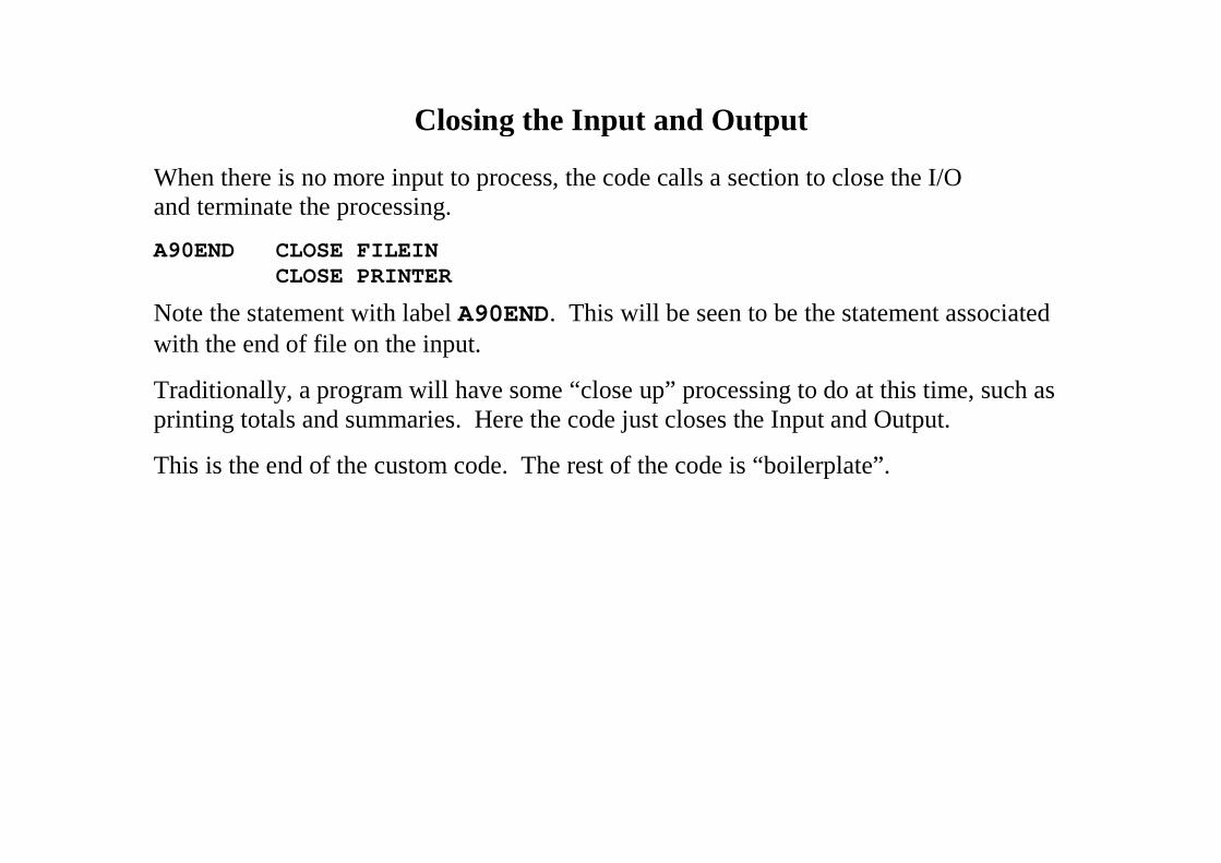
Closing the Input and Output
When there is no more input to process, the code calls a section to close the I/Oand terminate the processing.
A90END CLOSE FILEINCLOSE PRINTER
Note the statement with label A90END. This will be seen to be the statement associatedwith the end of file on the input.
Traditionally, a program will have some “close up” processing to do at this time, such asprinting totals and summaries. Here the code just closes the Input and Output.
This is the end of the custom code. The rest of the code is “boilerplate”.
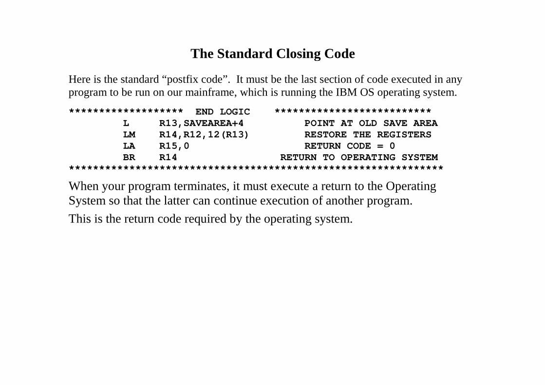
The Standard Closing Code
Here is the standard “postfix code”. It must be the last section of code executed in anyprogram to be run on our mainframe, which is running the IBM OS operating system.
******************* END LOGIC **************************L R13,SAVEAREA+4 POINT AT OLD SAVE AREALM R14,R12,12(R13) RESTORE THE REGISTERSLA R15,0 RETURN CODE = 0BR R14 RETURN TO OPERATING SYSTEM
**************************************************************
When your program terminates, it must execute a return to the OperatingSystem so that the latter can continue execution of another program.
This is the return code required by the operating system.
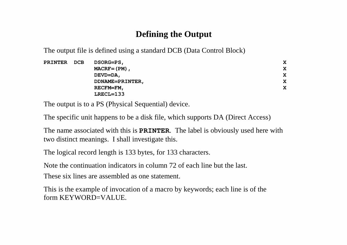
Defining the Output
The output file is defined using a standard DCB (Data Control Block)
PRINTER DCB DSORG=PS, XMACRF=(PM), XDEVD=DA, XDDNAME=PRINTER, XRECFM=FM, XLRECL=133
The output is to a PS (Physical Sequential) device.
The specific unit happens to be a disk file, which supports DA (Direct Access)
The name associated with this is PRINTER. The label is obviously used here withtwo distinct meanings. I shall investigate this.
The logical record length is 133 bytes, for 133 characters.
Note the continuation indicators in column 72 of each line but the last.
These six lines are assembled as one statement.
This is the example of invocation of a macro by keywords; each line is of theform KEYWORD=VALUE.
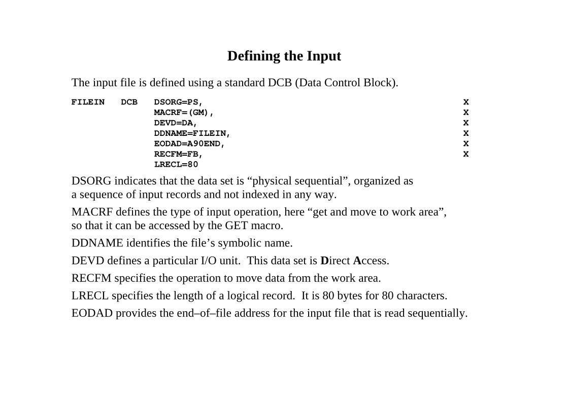
Defining the Input
The input file is defined using a standard DCB (Data Control Block).
FILEIN DCB DSORG=PS, XMACRF=(GM), XDEVD=DA, XDDNAME=FILEIN, XEODAD=A90END, XRECFM=FB, XLRECL=80
DSORG indicates that the data set is “physical sequential”, organized asa sequence of input records and not indexed in any way.
MACRF defines the type of input operation, here “get and move to work area”,so that it can be accessed by the GET macro.
DDNAME identifies the file’s symbolic name.
DEVD defines a particular I/O unit. This data set is Direct Access.
RECFM specifies the operation to move data from the work area.
LRECL specifies the length of a logical record. It is 80 bytes for 80 characters.
EODAD provides the end–of–file address for the input file that is read sequentially.
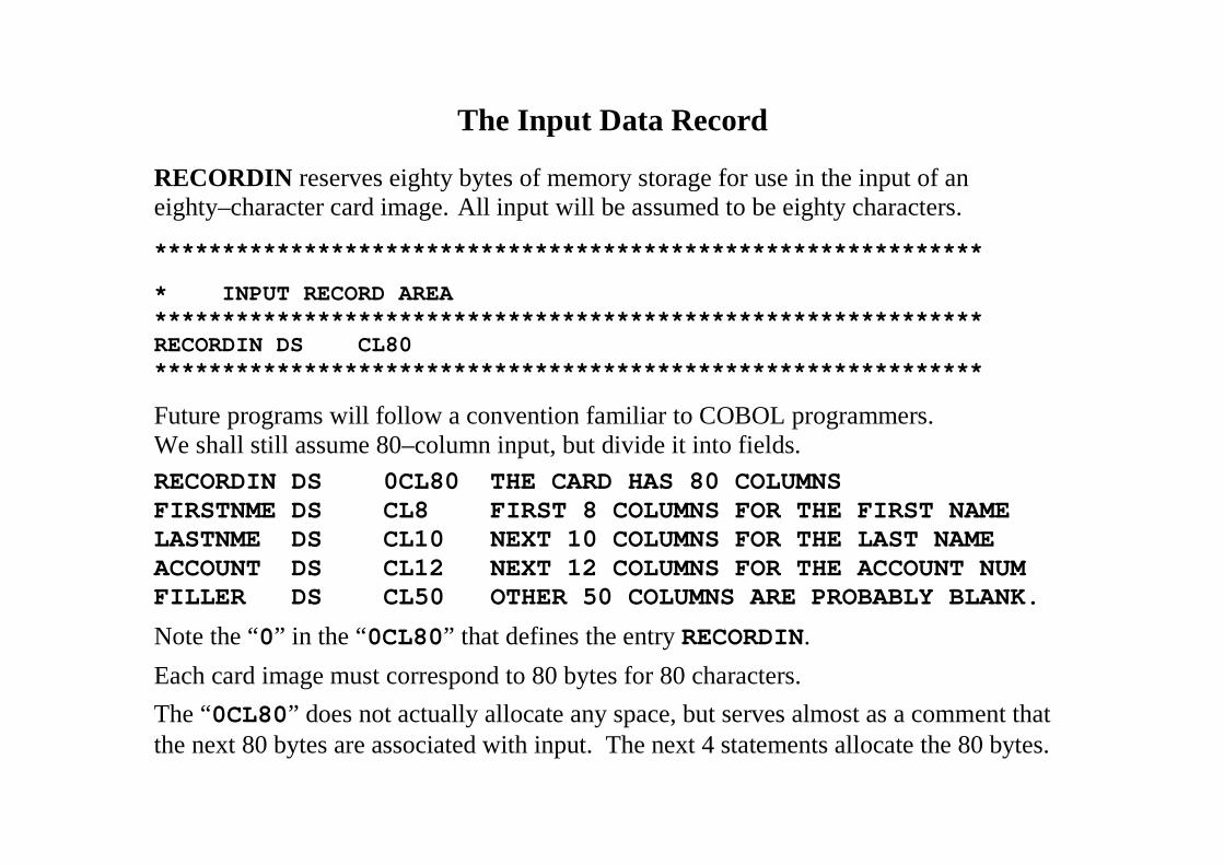
The Input Data Record
RECORDIN reserves eighty bytes of memory storage for use in the input of aneighty–character card image. All input will be assumed to be eighty characters.
*************************************************************
* INPUT RECORD AREA*************************************************************RECORDIN DS CL80*************************************************************
Future programs will follow a convention familiar to COBOL programmers.We shall still assume 80–column input, but divide it into fields.
RECORDIN DS 0CL80 THE CARD HAS 80 COLUMNSFIRSTNME DS CL8 FIRST 8 COLUMNS FOR THE FIRST NAMELASTNME DS CL10 NEXT 10 COLUMNS FOR THE LAST NAMEACCOUNT DS CL12 NEXT 12 COLUMNS FOR THE ACCOUNT NUMFILLER DS CL50 OTHER 50 COLUMNS ARE PROBABLY BLANK.
Note the “0” in the “0CL80” that defines the entry RECORDIN.
Each card image must correspond to 80 bytes for 80 characters.
The “0CL80” does not actually allocate any space, but serves almost as a comment thatthe next 80 bytes are associated with input. The next 4 statements allocate the 80 bytes.
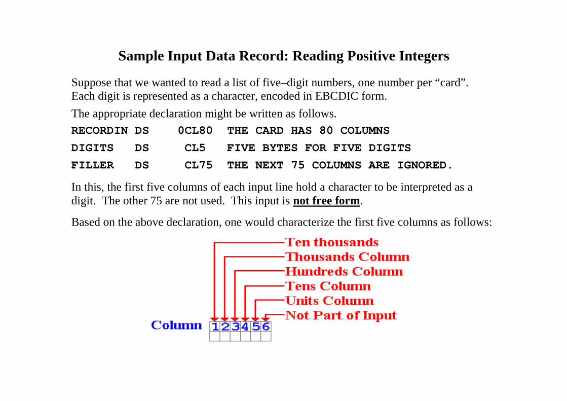
Sample Input Data Record: Reading Positive Integers
Suppose that we wanted to read a list of five–digit numbers, one number per “card”.Each digit is represented as a character, encoded in EBCDIC form.
The appropriate declaration might be written as follows.
RECORDIN DS 0CL80 THE CARD HAS 80 COLUMNS
DIGITS DS CL5 FIVE BYTES FOR FIVE DIGITS
FILLER DS CL75 THE NEXT 75 COLUMNS ARE IGNORED.
In this, the first five columns of each input line hold a character to be interpreted as adigit. The other 75 are not used. This input is not free form.
Based on the above declaration, one would characterize the first five columns as follows:
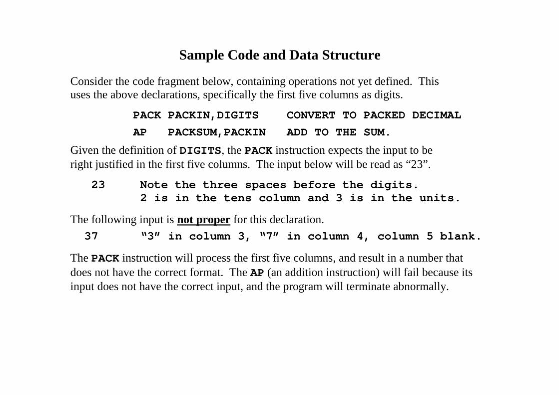
Sample Code and Data Structure
Consider the code fragment below, containing operations not yet defined. Thisuses the above declarations, specifically the first five columns as digits.
PACK PACKIN,DIGITS CONVERT TO PACKED DECIMAL
AP PACKSUM,PACKIN ADD TO THE SUM.
Given the definition of DIGITS, the PACK instruction expects the input to beright justified in the first five columns. The input below will be read as “23”.
23 Note the three spaces before the digits.2 is in the tens column and 3 is in the units.
The following input is not proper for this declaration.
37 “3” in column 3, “7” in column 4, column 5 blank.
The PACK instruction will process the first five columns, and result in a number thatdoes not have the correct format. The AP (an addition instruction) will fail because itsinput does not have the correct input, and the program will terminate abnormally.
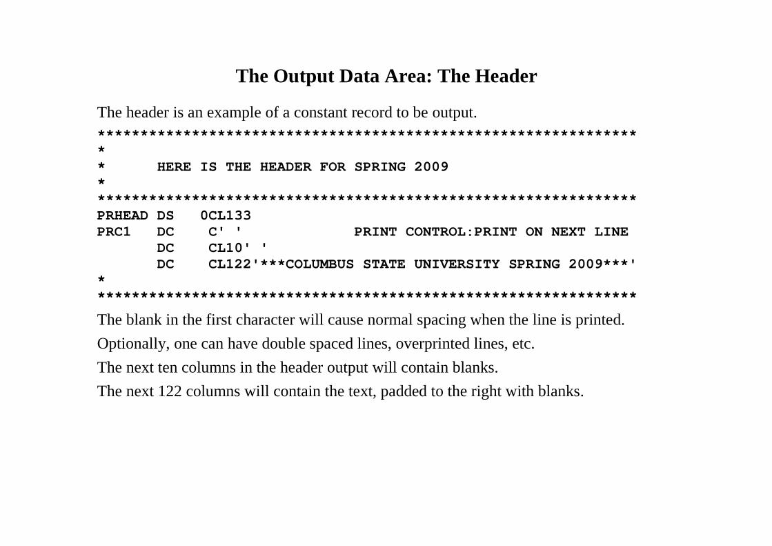
The Output Data Area: The Header
The header is an example of a constant record to be output.
***************************************************************** HERE IS THE HEADER FOR SPRING 2009****************************************************************PRHEAD DS 0CL133PRC1 DC C' ' PRINT CONTROL:PRINT ON NEXT LINE
DC CL10' 'DC CL122'***COLUMBUS STATE UNIVERSITY SPRING 2009***'
****************************************************************
The blank in the first character will cause normal spacing when the line is printed.
Optionally, one can have double spaced lines, overprinted lines, etc.
The next ten columns in the header output will contain blanks.
The next 122 columns will contain the text, padded to the right with blanks.
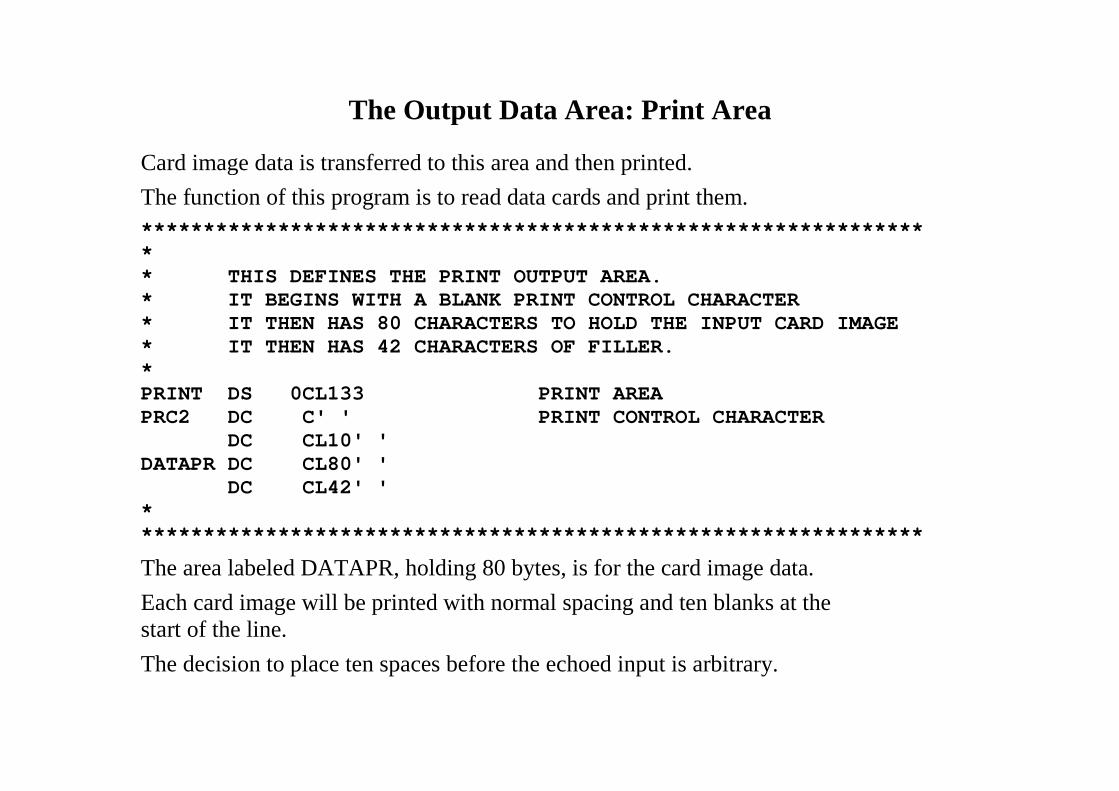
The Output Data Area: Print Area
Card image data is transferred to this area and then printed.
The function of this program is to read data cards and print them.
***************************************************************** THIS DEFINES THE PRINT OUTPUT AREA.* IT BEGINS WITH A BLANK PRINT CONTROL CHARACTER* IT THEN HAS 80 CHARACTERS TO HOLD THE INPUT CARD IMAGE* IT THEN HAS 42 CHARACTERS OF FILLER.*PRINT DS 0CL133 PRINT AREAPRC2 DC C' ' PRINT CONTROL CHARACTER
DC CL10' 'DATAPR DC CL80' '
DC CL42' '****************************************************************
The area labeled DATAPR, holding 80 bytes, is for the card image data.
Each card image will be printed with normal spacing and ten blanks at thestart of the line.
The decision to place ten spaces before the echoed input is arbitrary.
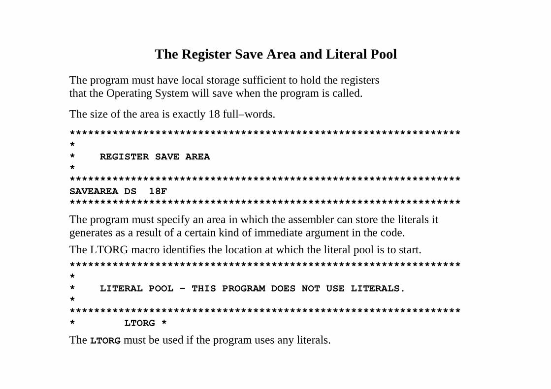
The Register Save Area and Literal Pool
The program must have local storage sufficient to hold the registersthat the Operating System will save when the program is called.
The size of the area is exactly 18 full–words.
****************************************************************** REGISTER SAVE AREA*****************************************************************SAVEAREA DS 18F****************************************************************
The program must specify an area in which the assembler can store the literals itgenerates as a result of a certain kind of immediate argument in the code.
The LTORG macro identifies the location at which the literal pool is to start.
****************************************************************** LITERAL POOL - THIS PROGRAM DOES NOT USE LITERALS.****************************************************************** LTORG *
The LTORG must be used if the program uses any literals.
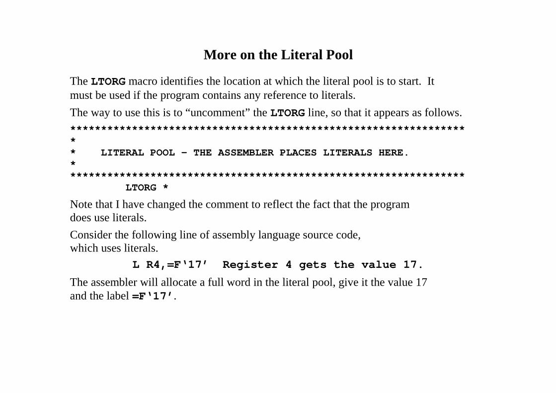
More on the Literal Pool
The LTORG macro identifies the location at which the literal pool is to start. Itmust be used if the program contains any reference to literals.
The way to use this is to “uncomment” the LTORG line, so that it appears as follows.
****************************************************************** LITERAL POOL – THE ASSEMBLER PLACES LITERALS HERE.*****************************************************************
LTORG *
Note that I have changed the comment to reflect the fact that the programdoes use literals.
Consider the following line of assembly language source code,which uses literals.
L R4,=F‘17’ Register 4 gets the value 17.
The assembler will allocate a full word in the literal pool, give it the value 17and the label =F‘17’.
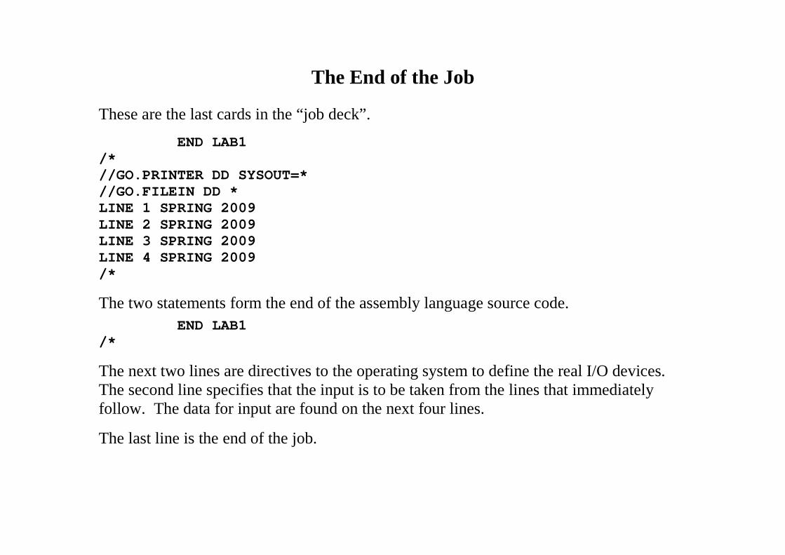
The End of the Job
These are the last cards in the “job deck”.
END LAB1/*//GO.PRINTER DD SYSOUT=*//GO.FILEIN DD *LINE 1 SPRING 2009LINE 2 SPRING 2009LINE 3 SPRING 2009LINE 4 SPRING 2009/*
The two statements form the end of the assembly language source code.
END LAB1/*
The next two lines are directives to the operating system to define the real I/O devices.The second line specifies that the input is to be taken from the lines that immediatelyfollow. The data for input are found on the next four lines.
The last line is the end of the job.