Embed Size (px)
Citation preview
Thomas D. GatlinVice President, Nuclear Operations
803.345.4342
A scANA COMPANY -November 10, 2015
Document Control DeskU. S. Nuclear Regulatory CommissionWashington, DC 20555
Dear Sir / Madam:
subject: VIRGIL C. SUMMER NUCLEAR STATION (VCSNS) UNIT 1DOCKET NO. 50-395OPERATING LICENSE NO. NPF-12RELIEF REQUEST RR-IIl-12 PROPOSED ALTERNATIVE INSPECTIONREQUIREMENTS FOR PIPING WELDS
Pursuant to 10CFR5O.55a(g)(5)(iii), South Carolina Electric & Gas Company (SCE&G),acting for itself and as an agent for South Carolina Public Service Authority, herebysubmits the attached request for relief from the volumetric requirement of ASME CodeSection Xl for the third ten year interval.
VCSNS has considered it impractical to achieve essentially 100% of the requiredvolume during performance of ultrasonic examination for some welds. The details ofthis request are contained in the Enclosure.
SCE&G requests NRC approval of the proposed alternative by October 1, 2016.
This letter contains no commitments. Should you have any questions, please callBruce L. Thompson at 803-931-5042.
Very truly yours,
Thomas D. Gatlin
WTITDG/ts
Enclosure : VCSNS Relief Request RR-III-12Attachment 1: Weld Sketches and Inspection Informationc: Without Attachments unless noted with an *
K. B. Marsh J. W. Williams K. M. SuttonS. A. Byrne W. M. Cherry NSRCJ. B. Archie L. D. Wert* RTS (CR-i15-04026)N. S. Camns S. A. Williams* File (810.19-2)J. H. Hamilton NRC Resident Inspector PRSF (RC-15-0161) •Ao(•'7
V. C. Summer Nuclear Station. P.O. Box 88. Jenkinsville, SC. 29065. F (803) 941-9776 - ( • =
Document Control DeskEnclosureCR-i15-04026RC-1 5-0161Page 1 of 3
South Carolina Electric & Gas Co. (SCE&G)Virgil C. Summer Nuclear Station Unit I (VCSNS)
VCSNS Relief Request RR-III-12
1. Subject
VCSNS requires relief from the volumetric requirement of ASME Code Section Xl, 1998Edition through 2000 Addenda for the inspection of piping welds. VCSNS has identifiedthese welds impractical of achieving the essentially 100% of the pressure retaining welddue to obstructions.
2. ASME Code Component(s) Affected
Relief is requested per 10 CFR 50.55a(g)(5)(iii) for the welds listed in Table 1. Thesewelds were inspected during the third inservice inspection (ISI) interval, but were not100% complete due to limitations. The welds were less than essentially 100%, but tothe extent practical using qualified equipment and personnel.
Table 1
Weld ID Caegory Item Percent LmttoWeld ID Categoy Item Complete Lmtto
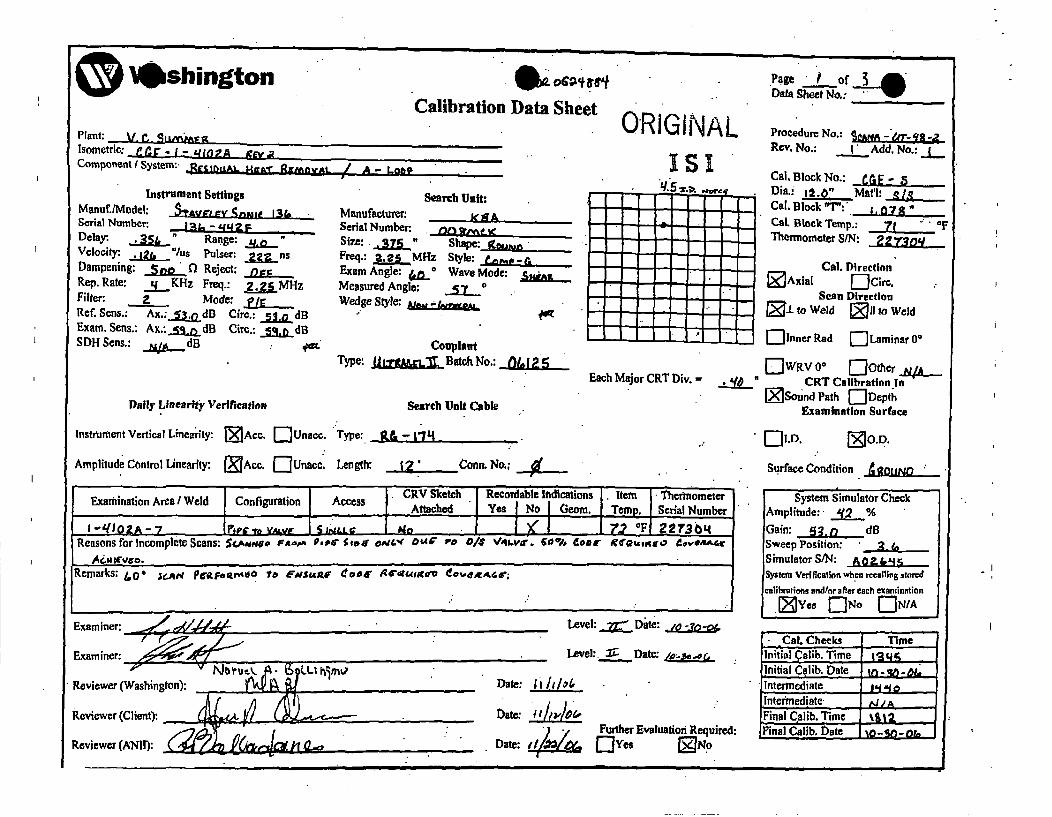
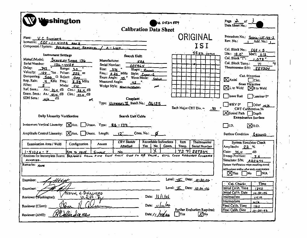
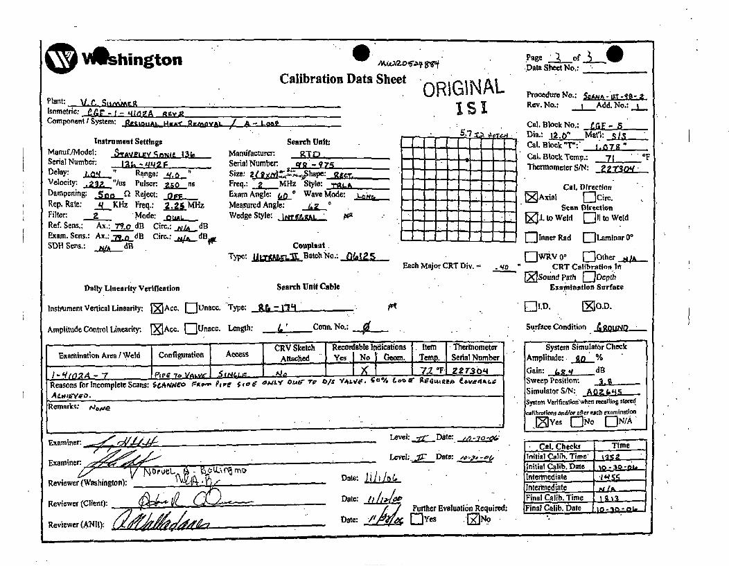
CGE-1 -41 02A-1 B-J B9. 11 50% Branch to pipe Scanned from pipe sideCGE-1-4102A-7 B-J B9.11 50% Single side pipe to valve
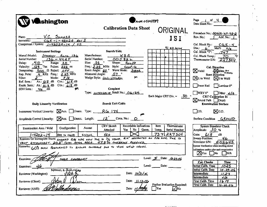
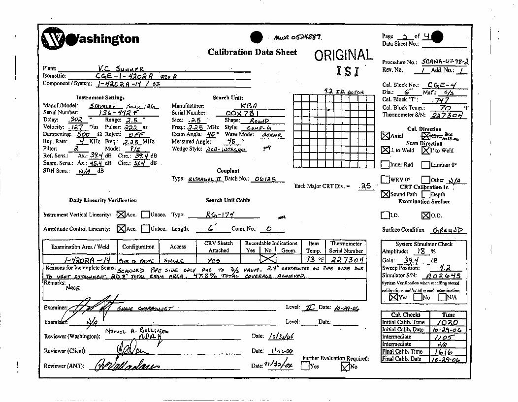
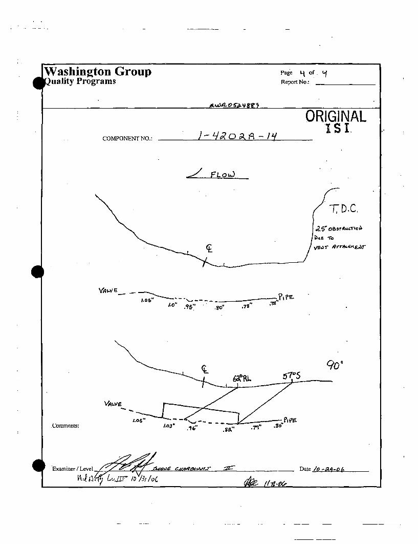
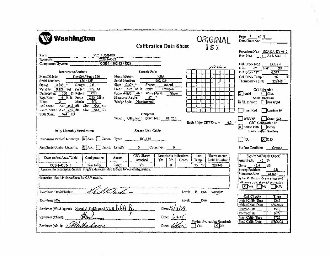
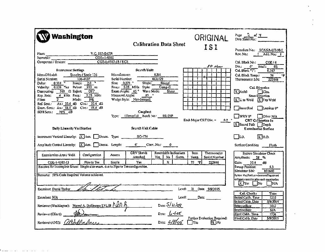
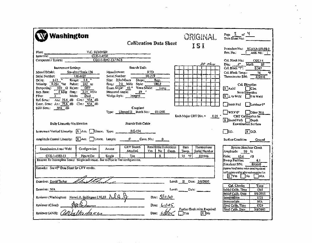
CGE-1-4202A-14 B-J 89.11 47.8% Single side pipe to valveCGE--450-13 B-J 9.11 50% Single side exam due to pipe to teeCGE--450-13 B-J 9.11 50% configuration
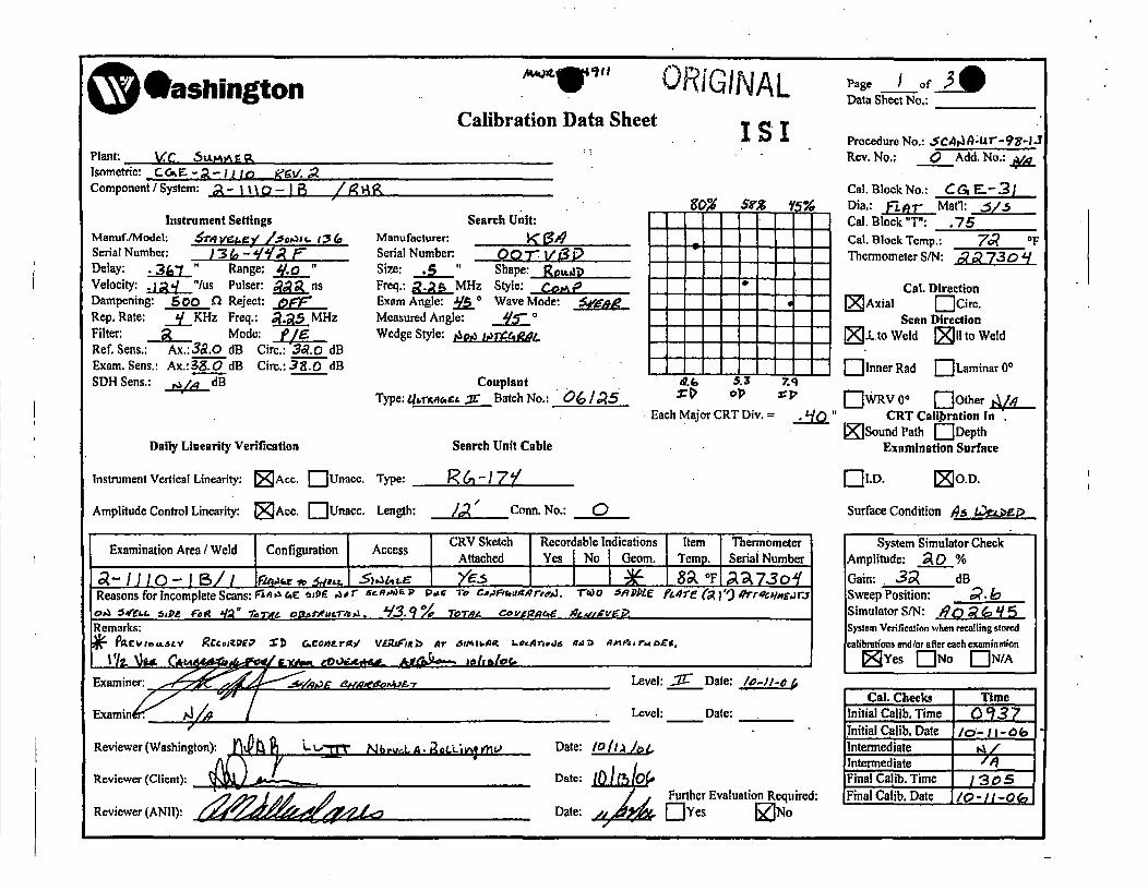
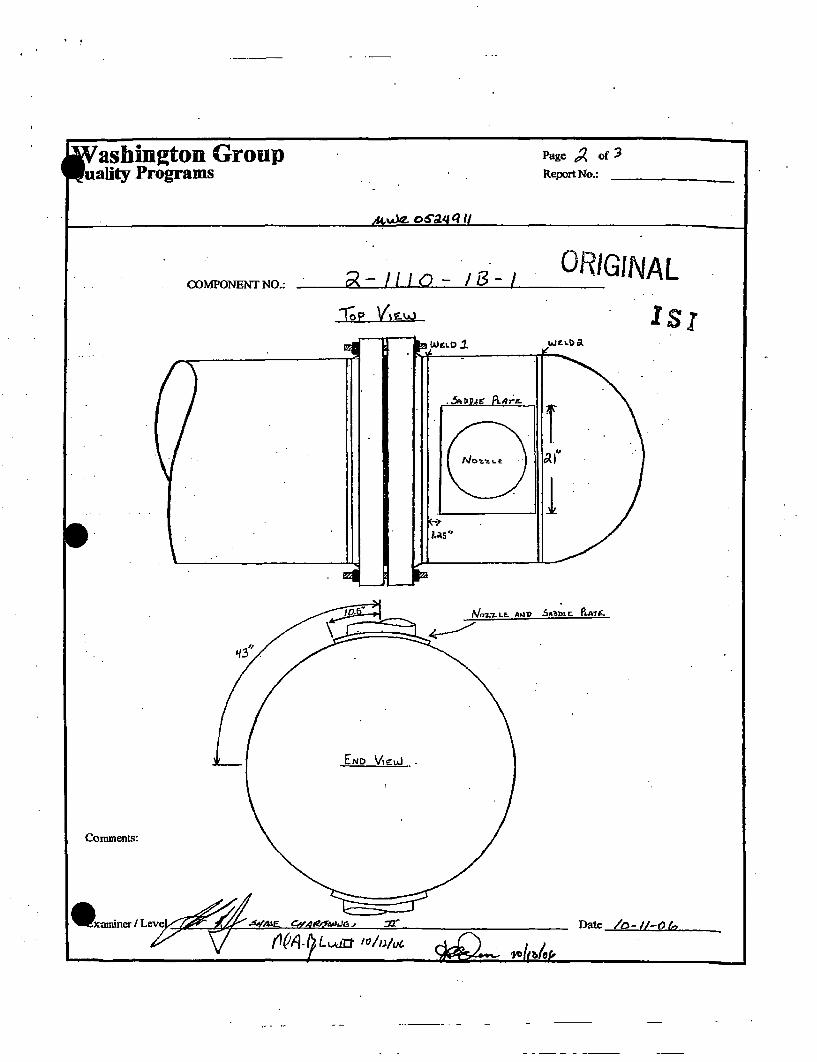
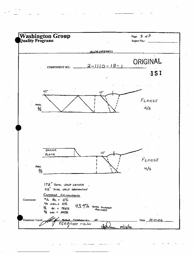
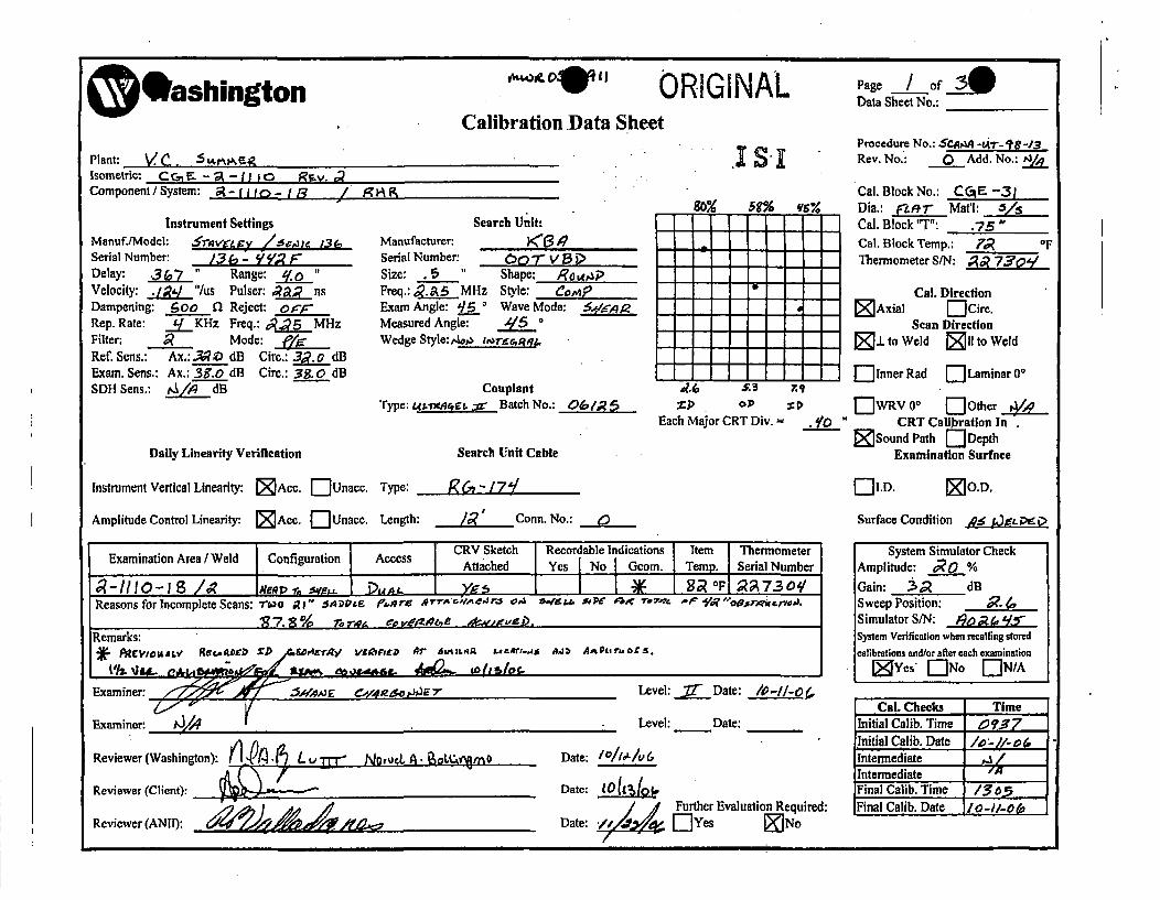
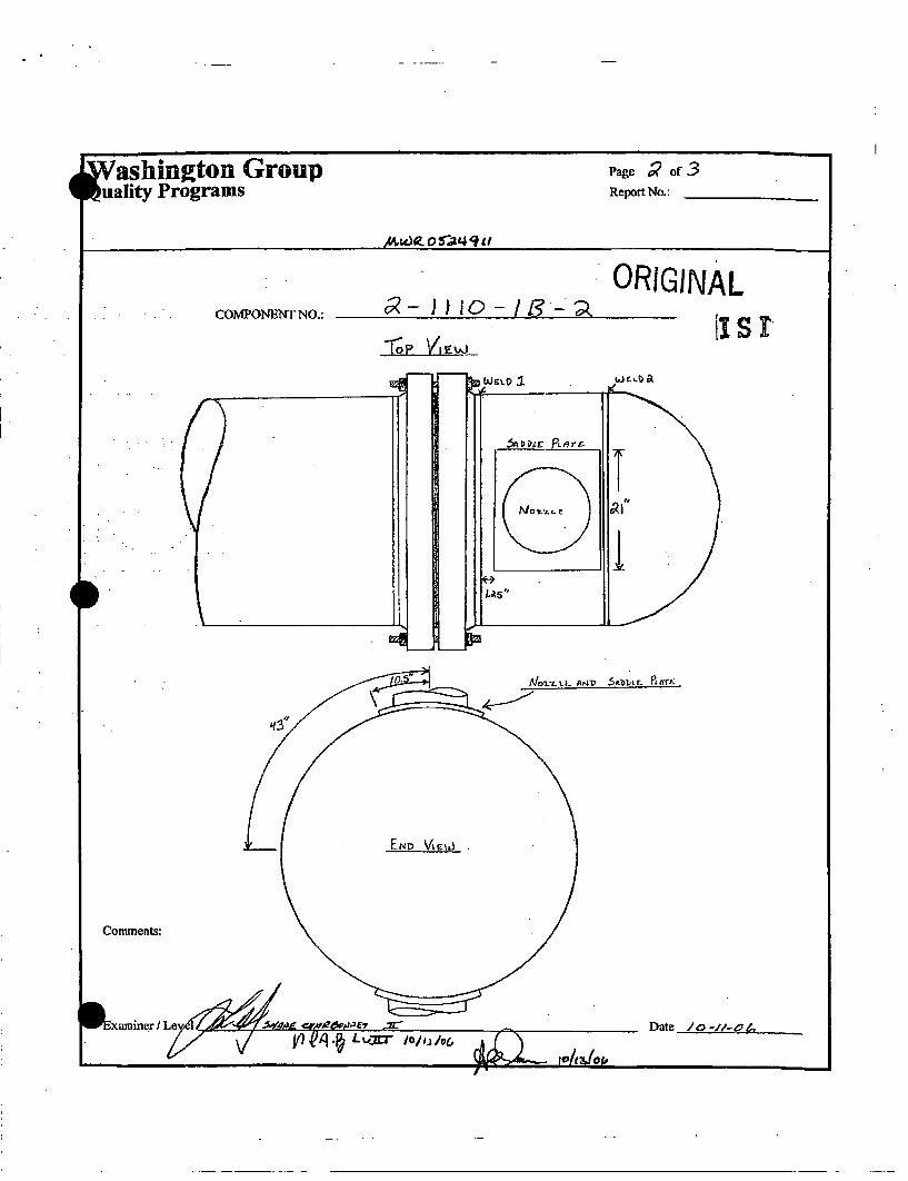
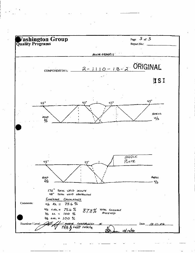
CGE-2-1110-1B/1 C-A C1.20 43.9% Scanning limitation due to Saddle plateCGE-2-1 110-1 B/2 C-A C1 .20 87.8% Scanning limitation due to Saddle plate
3. Applicable Code Edition and Addenda
ASME Code Section Xl, "Rules for Inservice Inspection of Nuclear Power PlantComponents," 1998 Edition through 2000 Addenda.
4. Applicable Code Requirement
ASME Code Section Xl, Division I, "Rules for Inspection and Testing of Componentsof Light Water Cooled Plants."
Article IWB-2500, "Examination and Pressure Test Requirements"Table IWB-2500-I, "Examination Categories"Article IWC-2500, "Examination and Pressure Test Requirements"Table IWC-2500-1, "Examination Categories"
Document Control DeskEnclosureCR-I15-04026RC-15-0161Page 2 of 3
ASME Code Case N-460, "Alternative Examination Coverage for Class 1 and Class 2Welds Section Xl, Division 1"
5. Reason for Request
Pursuant to 10 CFR 50.55a(g)(5)(iii), relief is requested from the ASME Code volumetricexamination requirement for the welds listed in Table 1. Relief is requested fromachieving essentially 100% of the required volume during performance of the ultrasonicexamination when component design and geometric limitations preclude a completeexam.
VCSNS has adopted ASME Code Case N-460, "Alternative Examination Coverage forClass 1 and Class 2 Welds Section Xl, Division 1," which states that when the entireexamination volume or area cannot be examined due to interference by anothercomponent or part geometry, a reduction in examination coverage on any Class 1 orClass 2 weld may be accepted provided the reduction in coverage for that weld is lessthan 10%. The applicable examination records shall identify both the cause andpercentage of reduced examination coverage.
10 CFR 50.55a(g)(4) states that Class 1, Class 2, and Class 3 components must meetthe requirements set forth in the ASME Code, Section Xl, to the extent practical withinthe limitations of design, geometry, and materials of construction of the components.
The limitation for examination is due to physical design of the plant in which avolumetric limitation is encountered due to the physical configuration of the component.The general design of the component surfaces may also have ultrasonic scaninterference caused by inherent manufacturing geometry or obstructions that precludeaccess to the weld area. Table 1 provides a description of the limitation for each weld.Each weld was examined to the maximum extent practical to include the use of multipleangles and beam paths.
6. Proposed Alternative and Basis for Use
Examination of welds/components was conducted using personnel, equipment andprocedures qualified in accordance with ASME Section XI, 1998 Edition through 2000Addenda. VCSNS has examined the subject welds to the maximum extent possibleutilizing approved examination techniques and equipment. Based on the limitedcoverage achieved by the examinations performed, it is the station's position that thelimited examinations provide a reasonable assurance of quality and safety.
Document Control DeskEnclosureCR-I15-04026RC-l15-0161Page 3 of 3
7. Duration of Proposed Alternative
This request for alternative requirements for the inspection of piping welds is requestedfor the third ISI interval, which started on January 1, 2003 and endedDecember 31, 2013. In accordance with ASME Code, Section XI, ParagraphIWA-2430(c)(1), VCSNS extended the third ISI interval by one year to end onDecember 31, 2014.
8. Precedents
VCSNS submitted a similar relief request on September 16, 2003 for the second ISIinterval (References 1, 2 and 3). Welds CGE-1-4102A-7 and CGE-1-4502-13 wereboth included in the September 16, 2003 relief request for the second ISI interval.
9. References
IJeffrey B. Archie (VCSNS) letter to Document Control Desk (NRC), "Resubmittalof Request to Use Alternatives to ASME Boiler and Pressure Vessel Code,Section Xl, (C-02-3202) RR-II-9, RR-II-10, RR-II-11, RR-II-12," dated September16, 2003. [ML032690223]
2 Jeffrey B. Archie (VCSNS) letter to Document Control Desk (NRC), "Response toRequest for Additional Information Regarding Request to Use Alternatives toASME Boiler and Pressure Vessel Code, Section Xl Relief Request RR-II-09 andRR-II-10 (C-02-3202)," dated June 22, 2005. [ML051780379]
3 Evangelos C. Marinos (NRC) letter to Jeffrey B. Archie (VCSNS), "Virgil C.Summer Nuclear Station - Second 10-Year Inservice Inspection, Request forRelief RR-Il-09, RR-II-10, and RR-II-12 (TAC NO. MC5750)," dated January 20,2006. [ML0601 00448]
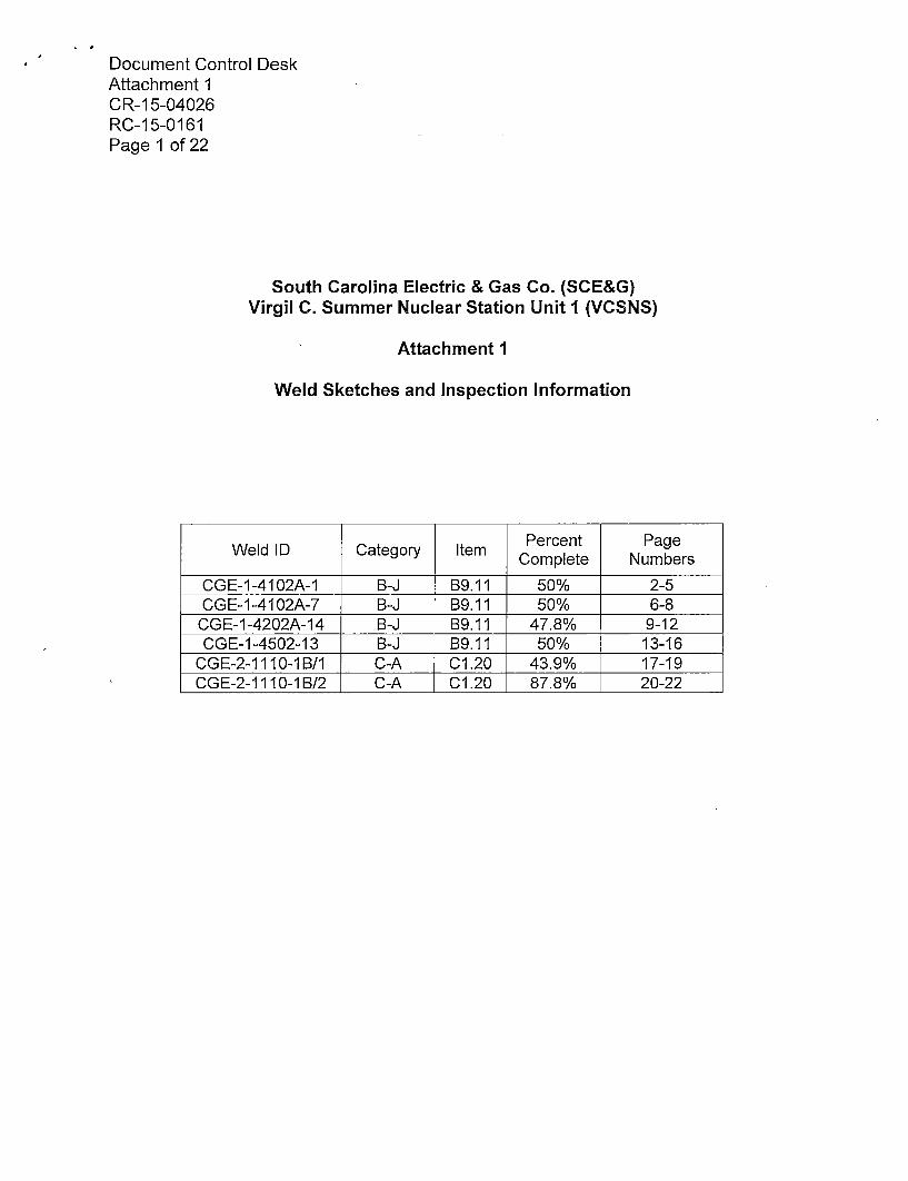
Document Control DeskAttachment 1CR-i15-04026RC-1 5-0161Page 1 of 22
South Carolina Electric & Gas Co. (SCE&G)
Virgil C. Summer Nuclear Station Unit I (VCSNS)
Attachment 1
Weld Sketches and Inspection Information
Weld ID Category Item PretPgComplete Numbers
CGE-1-4102A-1 B-J B9.11 50% 2-5CGE-1-4102A-7 B-J B9.11 50% 6-8
CGE-1-4202A-14 B-J B9.11 47.8% 9-12CGE-1-4502-13 B-.J B9.11 50% 13-16
CGE-2-1110-1B/1 C-A CI.20 43.9% 17-19CG E-2-1110-1B/2 C-A 01.20 87.8% 20-22
I II I III I III II • . .. , .. .. •A •
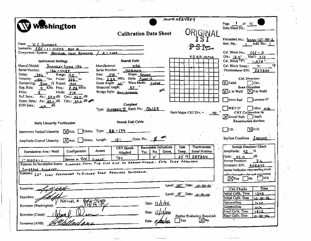
V hington . j~A~AJC O~A'~t'f:. Page "1 of l- e
Data Sheet No..: _______
Calibration Data Sheet 'J'~IUJIVALIs'Plant: V. •. u•FIsometric:: t•f" - I- '4102A Rsy~ ,RComponent/ System: ;~,LHr EMVL/A O• .
Procedure No.:Rev. No.: -----add.No.: JL
Cal. Block No.: j....
Cal. Block Temp.: 7l j 0 FThermometer S/N:.
Instrument SettingsManufiModeh: SrAVS'LaV oIe 131,Serial Number: I gh -s142 z,Delay: ,•Sb" Range: •,Velocity: .I*t "/us Pulser: fns
Dampening: See ) Reject: .. EL......Rep. Rate: ._±IKHz Freq.: 2.5MHzFilter: ____ Mode: • IRef. Sens.: Ax.: bjdB Circ.: •.j dBExam. Sens.: Ax.: •i1 ~odB Circ.: _•.•dB q$'SDH Serts.: .. &__dB
Daily Linearity Verification
Search Unit:Marnifacturer: i•,ASerial Number: ______________
Size: • " Sae loAeFreq.; 2 .Z5 MHz Style; Pn•,aExam Angle: ..h 0 Wave Mode: gd'uMeasured Angle: _• oWedge Style:
CouplantType: j Batch No.:
Cal, Direction- l--IXrAxial ECirc.
I Scan DirectionI "i J.Lto Weld I-'Illto Weld
I EI-o~ner gad E--Itaminar0"
-l]wPRV 0o D--Other a..! _* 'to " CRT Calibration Ifl
•Sound Path [l DepthExamination Surface
Each Major CRT Div. =
Search Unit Cable
Instrurment Vertical Linearity: [•IAcc. f--lUnacc. Type: R.&, - l|"'i [•]!.D. SJo.D.
Amplitude Control Linearity: [•Aco. E--Unaee. Length: '_.j ._.Conn. No.: ,' :
CR.v Sketch Recordable Indications .Item' TherometerExamnination Area/IWeld Configuration Access Attached Yes i No I Geom. Temp. Serial Number
Reasons forinaomplete Scans: S•.,,o itaa• V,'5 •IO bLA 70 64A1'.a 1ota•., 5io,'V. Leor AdrQa,xvo
Remarks: ~,O' £C.A'J 7~A%~ORfl~a'O re ~iS~4WU' ~ GUjt5~O
Surface Condition .A OU.ND--
System Simulator CheckAmplitude: ±L.I.•,__Gain: • .d l.._dSweep Position: •. ati.-.-Simulator S/N:.System Verification whena recolliing stored.eat bralkgu anAMnr aler each exnomination
Cal. Checks Titne'Initial •alili. Time t~qInitial Calib. Date In*o t,Intermnediate c•trnterredia'te N.FinalC~alib. Time • ••Final Calib. Date o. -o=_
Level: ., =Date: .. o- I -a4
Level:. .aZ Date: /,---¢
Date: •l ,!d Further Evaluation Required:Date:esI-SIr[N~o
i t
O V shington
Plant' V C. Sm, luv•ct•
Isometric: I•"~ - f- '4162A R1av,Com~ponent/[System: •E'eI0ZAL UKAT REMI1VAL
Instrument SettingsManuf.iModel: SIrAvELEY Sn•IeL 13 CSerial Number: !_ - zjqj FDelay: .3"1 Range: j.•"Velocity: 1.. ,'/us Pulser: nDampening: ..5lQ fl Reject:Rep. Rate: ..j..K~lz Freq.: ,•gMHzFilter: 2 Mode: PLRef. Sens.: Ax,:35qd Circ.: 3• dBExam. Sens,: Ax,: 4 .,€dB Circ.: 53.,.dBSDH Seais,: g•dB
Daily Linearity Verification
McoRo~&4yri
Calibration Data Sheet
/ ,A-.Loa9
ORIGiINALSIs
.Page j•_ ofData Sheet No.:_
Procedure No.: SOAL 'g,9. =.Rev. No.: j Add. No.: .L
Cal. Block No.: j GEDia.: 120"Matl: SICal. Block 'T': 10Cal. Block Temp.: *1 .. FThermometer SIN:
Search Unit:Manufacturer: l( gASerial Number: nrrrq kSize: .•. Shape: p•,gFreq.: •.2jMHz Style:Exam Angle: q.¢ Wave Mode:Measured Angle: q2_Wedge Style: • #
CouplantType: •jgj Batch No.:
Each Major CRT Div. =
Cal. Direction* - - Axial EJ:Circ.
Scan Directionl-•zto weld [lt to Weld
{--"]nner Rad El]Laminaro0°
F-lwRV 00 E-l other..,a•30 " CRT Calibration in
[--)(Sound Path ['-Depth
Examination SurfaceSearch Unit.Cable
Inst nrumnt Vertical Linearity: [•jAcc. [--Unatec. "Type: Ri!.- -Flti
Amplitude COntrol Linearity: [•]Acc. E-'Unacc. Length: 12'.,Conn. No.:
CA ktachd k ecordable indications It-mThermometerExmntora(ed Cnuaio ces Atce e o Gon Tern . Serial Number
Rleasons for Incomplete Scans: •€•u,•o r•,,• PI9,E $uaac ouE• -ro BIcM.AAC Ado .? . ,•e d~ooe tIE,&,,etIC o j,,,lAt
Remarks:
ElI.D. j ~O.D.
- Su~rface Condition ON
System Simulator CheckAmplitude: .. %
Gain: 2,.j dBSweep Position: •. 6******-Simulator S/N:._L .. l--Syslem Verification when recalling storedl
calibrations andfor after each exan'ination.Ij~esoEN EN./A
Reviewer (Washington): . •••
Reviewer (Client): "
Reviewer (ANll): . . .
Level: :x2 Date:1-o- .
Lever: •._•. Date:
Date: hj\ It /e.
Date: I/l/.Dae / ,F]eFurther Evaluation Required:[•
'Cml. Checks Time'nitial (crlib. Time, I;qInitial Ca lib. Date •o o-,Intermediate 2olntermnedi~ate •IFinal C alib. Time .1811....-.Final Calib. Date to -s$0 -o¢

I . I I I i I
@ •lshington
Plant: y. c. •t•(te•Isometric: I!I.F - I - '4iD2A RLgya
Component/ISystem: I•£unOIAL 1a'A1I REmOVAl.
Instrument SettingsManuf.IModeh: S'TAVrE'Y SpENIC. 131o.Serial Number: !_______- ________
Delay: J {.a_." Range: 0,o "Velocity: • "'/us Puiser: j50nsDampening: •jgL Reject: .DEL....Rep. Rate: __f.KHz Freq.: 2. MHz
Filter: 2._.,. Mode: OmRef. Seas.: Ax.: 79,0dB Circ.:_l dExam. Seas.: Ax.: 7•OdB Cire,: •~dB '
SDB Sens,: .. dB
Daily Linearity Verification
S.Calibration Data Shoe t
Is'51 .7 ~ ,•rc. .
Page " of of L '"Data Sheet No.
Procedure No.:Rey, No." j Add. No.: -L-
Cal. Block No.: fDia.: 12.0', MatI.:_/Cat. Block"T":" f. 07 g"
Cal. Block Temp.: 71 °....FThermometer S/N:
/ A- Lone
Search Unit:Manufacturer: •yj-OSerial Number: g•- 9'Size": ' S(~hape"uFreq.: L•Mlz Style: "r~.A.Exam Angle: hOn Wave Mode: b0•Measured Angle: 2°
Wedge Style:
CouplantType: jj •j Batch No.:
Cal. Direction- jAxial El_'Cire.
Scan Direction,- - •. to Weld E•li to Weld
- - '-lInner Rad E"Laminar 00
EI]WRVy00 [--Other j. qO " CRT Calibrntion In
• Sound Path E•DepthExamination Surface
Each Major CRT Div. =
Search Unit Cable
Instrument Vertical Linearity: [•Acc. E''Unacc, Type: R.& - 't. .
Amplitude Control Linearity: [•Aec. E'lUnate. Length: /.'Conn. No.: •
ExainaionAra /Wel Cofiuraion Accss CRV Sketch Recordable Indications .Itefn .Thertnometer
Exaintin rea/ el Cnfgurtin ccss Attached Yes [No Geom. Ternp. Serial Number--. A-.[1RPP'o. ( • FZTO
Reasons for Incomplete Scans: Sc~ea OuhRorm•L ?1oc lOue I0 o 8EAAC.M Maezt.LG, 50oe Ceovr g•II=,,~o
Remarks:
EIl.D. •O.D.
Surface Condition .&~~~
System Simulator CheckAmplitude: •0Gain: ta.q dBSweep Position: ,.3 •Simulator S/N:Syslrni Verification when .,ca~lhnB stored
:nlihraliOaa sndfor aifter each exaniintidonY Es o~ E /
[-Cal. Checks Tfime[Ini~tial •alib. Time *i|.3.---Initial Calib. Date |6 ag -tQrntcrmediate 6•Intermediate !Final Calib. Time 'IlFinal Catib. Dlate l0"o-tt
Level: -"7•Date:
Level:. •._ Date:
Dat:IlIIIi
Date: fl-ia.-,-1, Further Evaluation Required:Date: l-"Eves 5"No
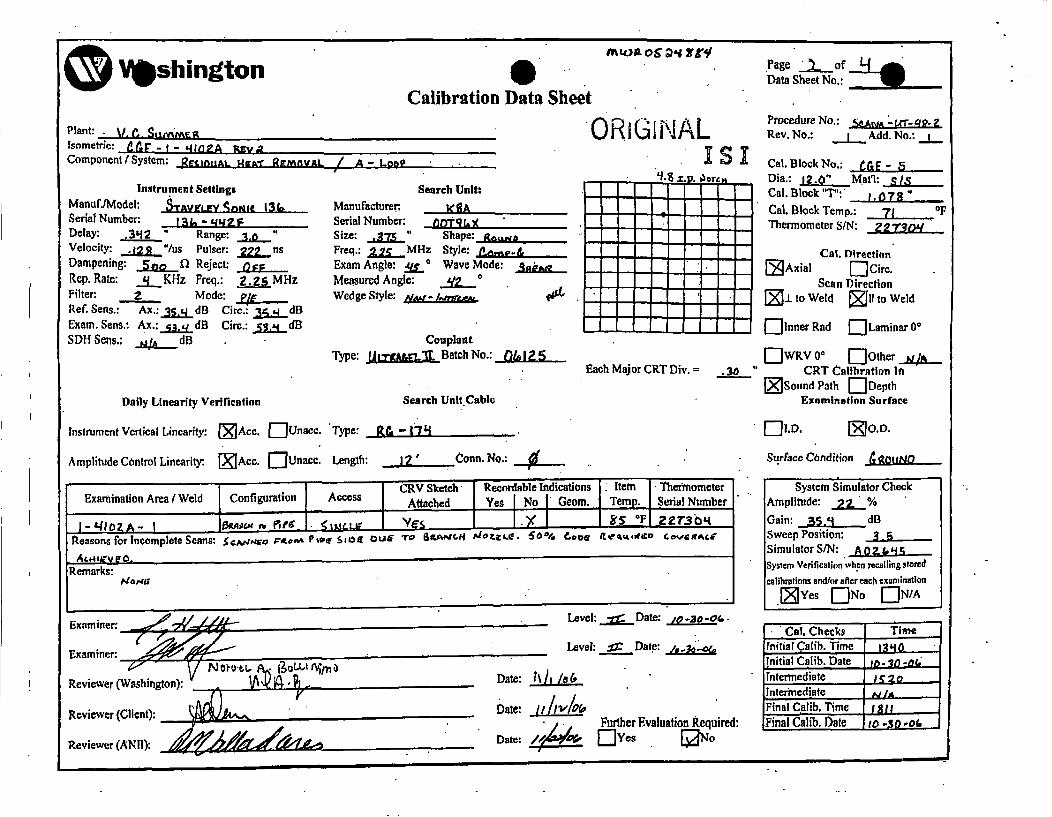
Washington Group~uality Programs
/ - Hi io~ri- ICOMPONENT NO.:
570*5
- --- =
e PE.-
'4' I JO* 1.1¢"
Comments:
Examiner / Examier /Date IO-RO-ot.
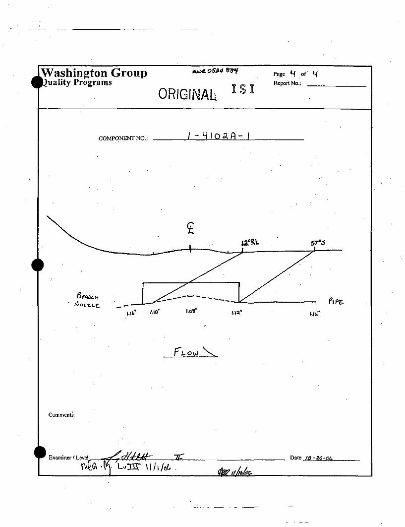
Oq shungton
Plant: V. • SttL•_ M•isometric: •I!1V-I" - '." IO•A •ev,Component / System:• Jra'rI•nAL s.Ia-r 0
WAAOVAj
Instrument SettingsM anuf.IM odei: .• v ' v € n • 1 L .Serial Number: ;t, - g4p2[Delay: _.5 " Range: t~ ""Velocity: .I. "/us Pulser: ..ag.n.fsDampening: • Q Reject: E....Rep. Rate: jIKHz Freq.: 2gj MHzFilter: 2 Mode:Ref. Sens.: Ax.;•dB Circ,: _,.1~dBExam. Sens.: Ax.:. Mj.dB Circ.: •q.•dBSDH Sens.: •dB . 4.
Daily Linearity Verification
Calibration Data Sheet ORIGINAL
/ A,-Loa9 ]Is
Page 1 ofData Sheet No.: ~
Procedure No.: -h•fL r2.=._.._._Rev. No.: IL Add. No.: _
Cal. Block No.:Dia.: 12.b" Mat'l:Cal, Block ST":" 1 Og"
CaL. Block Temp.: j J 0 FThermometer S/N:
Search Unit:Manufacturer: I( pASerial Number: 00 f,-Ae-CSize: -,3L Shape: g•Freq.: &I MHz Style:Exam Angle: •D. Wave Mode: .Measured Angle: _.5.t..._°Wedge Style: •[L/atu
CouplantType: Uj• Batch No,: .f•~.
Cal. Direction*1- Axia[ [CanLiirc,
tjj .ito weid F-l to Wei~d
Li - --innet Ra.d E']Laminar oE WRVO- EOther .a
• __• " CRT Calibration Itij•Sound Path jl-Depth
Examination Surface
Each Major CRT Div. =
Search Unit Cable
lnstArfment Vertical L~inearity: IZ•2AcO. I-'Unacc. Type:, R.& -l/ . '. I-- I ..~OD
Amplitude Control Linearity: (•jAcc. [--LUnacc, Length: j2' onnt. No.: Surface Condition .. &LWQZ.
1 .CRV Sketch Recordable Indications .Item ThenfnometerExmnto ~ ed Configuration Access . Attached IYea I No 1 Geom. Temp. Scrial Numberqi" 2-7 . 0p'r ~v ~ •• o[• . F 22T'364
Reasons forlIncomplete Scans: $u•..i€. P*~A P.a %e,U?-¢e •.•. O>UG ,.o 01*r V4L,.v. •od9I. •@OI •(Gu,e~ro •ovEA
System Simulator CheckjArplitude:.q %~Gain: jI•d dSweep Position: •Simulator S/N: &. 1 ~5System Verillcation wh~ci re-alling stored
cnlibhei;otis and/ar afier each examination
Examiner: Level: .2•Date:
f Jm • 1 m
• •/ •L I L
_ . Level:. :Z Date: OS.d.
Reviewer (Washington):
*Cal. Cheeks' TimeInitilaiCalib. Time , 1jjqr*Initial Calib. Date : n- -Intermediate '0Intermediate •/Final Calib. Time jjz*.Final Calib. Date •O•-r
Reviewer (Client): Date: 1J•//d•,
Reviewer (ANII): I 1 ilFuIher EvauaIo Reur:
-- "-- __ Z :7 . ... I II
SshingtonCalibration Data sheet
Page "• cf 3'Data Sheet No.:
Plant: V.• Sut'M r__Isometric: t1r" - - n/ • .Component/ISystcni: alflntl XA•jwA Refoval.
Instrument SettingsManufjModel: SIAVP&Y Snumt 13 ...Serial Number: _t at, - g'gDelay: • " Range: _.0._Velocity: _d2.j__"us. Pulser: zZ2 •.nsDampening: .. f Reject: OD.E....Rep. Rate: 2LKHz Freq.: Z.g.MHzFilter: 2 Mode:Ref. Seas.:. Ax.:.•.. &dB Circ.: •qdExam. Sans.: Ax.:_, dB Circ,: _•.dBSD1- Sans.: .• ._dB
Daily Linearity Verification
/' A- Ln • ,
ORIGI NALIs'
Search Unit:M anu facturer: __ _ _ _ _ _ _ _ _ __A_
Serial Number: Nr/.t•T' ('Size: ~.I..7.•" Shape: :, 8 ,b _Freq.: .2.MHz Style:Exam Angle: -_q C Wave Mode:Measured Angle: .L 0+Wedge Style,: • ,:.
Couplant,Type: J •~ ~Batch No.:
Procedure No.:Rev. No.: .__Add. No.:
Cal, Block No.: •Die.: 12.O' ==Mat'l:Cal. Block 'T': '.. .•.Cal. Block Temp.: J °FThermometer SIN:
Cal. Direction'[ Axial E'Cire.
Scan Direction[5J. to Weld [5Ill to Weld
E-'Inner Rad [--']Laminar 0°
l--WRv oo E--other" CRT Cailhratlnn Int
[•Sound Path ["-DepthExamination Surface
Each Major CRT Div. = .
Search Unli'Cable
lnstrtirnent Vertical Linearity: [ZACC. []Unacc. Type: R& - f"/
Amplitude Control Linearity: j[jAcc. ElUnaee. Length: j•..Conn. No.:
F--LD[ZO.D.
Surface Condition .
( ( (CRV Sketch" Recordable indications ].Item T "h~ometarExamination Area I Weld Configuration Access Attached Yes [No tGeom. [Tamp. [Serial Number
-~ fpi ,i72 0F Z7~
Actuaub.Remarks:
System Simulator CheckAmplitude: .. ej_%
Gain: ,35,q dBSweep Position: • .Simulator S/N:.jSystem VerifiCation when recalling stmrd.
t•lJb'egtotog and'or a+fer each exnJmi~nalo+Ys f~ EN/, A
Examiner:.•'.• . . .. . , I m
1- 1- v
Reviewer a~shington):
Reviewer (Client):
v~11f~~ m
________ Level: ,• Date:. •..•o -
Level: . Date: • -0,
Date: ii/h/•
Date: .LL• Further Evaluation Required:
.Cii. Checks T~imeInitial (alib, Time #31Initial Ca lib. Date Io-2O-O•-Intermediate - 4;lintermedi~ate / •Final C alib.Time I jjjjFinal Calib. Datae L.)- oQ
i
Reviewer (ANII):
...... .. .. i • ill __ ... .. • i
4 s'hingtonCalibration Data Sheet ORIGINAL
Is'
- w , , ,
Plant: y. i,_ Stiv'ard, •Isometric: •g' -- q4n[A 4avS•Component I System: I2 ~tmouAL 4-g•Ar IRE.'nVRL
Instrument SettingsManufUModeh: S',Vt.AV'LV StnNI 13hSerial Numbei: I; t.+qq2IDelay: .LL " rnige: .•2Velocity: .az..."/us Pulser:.. nasDampening: .. oa_ Reject: ~Rep. Rate: 2LKHz Freq.: 2...2= MHzFilter: 2 Mode:Ref£ Sens.: Ax.: 79...._0 dli Circ,: • dlExam. Sens.: Ax.:. •2.dB Circ.: d gSDH Seos.: _2/A..dB
Daily Linearity Verification
I -- La,.
Search Unit:Manlfacturer: RJ' D_Serial Number. • 9•. 's
Freq,: J••_.MHz Style: TLExam Angle: •O.. Wave M~ode: Lcr.Measured Angle: ._4•.Z...Wedge Style: • /•
Couplant.Typ: •lM~Batch No.:
.Data Sheet No.: '.____
Procedure No.: -;dtb.:K .Rev. Nqo.: ._LAdd. No.: -.
Cal. Block No.: JE ,
Cat, Blovk Tenip,: jjj 0 '" FThermometer SIN:
Cat. Direction• Axial EIICirc.
Scan Direction[•ILto Weld Eli" to Weld
[--'Inner Rad [-- Laminar 00
IZ••vo 0 Other zJCRT Calibration int
[''Sound Path • et
Examination Surface
Each Major CRT Div. = .q
Search Unit Cable
lInstrtiment Vertical Linearity: •Acc. EOUnaco. "Type: &kP.lt±-.tl.- "----.'. DTI.D. So.D.
Amplitude Control Linearity: •Acc. l-"IUnacc. Length: __L Conn. No.:
-remarks: Al.~I
Surface Condition. u~-System Simulator Check
Amplitude:.. %
Gain: •,fq dfSweep Position:Simulator S/N: &. &.i-System Verification"whn r~ca~liing storedj
• •mlubto~ and jornfer eac.h examinatioa
, Cal. Check• ~Time
Reviewer (Washino): •, Date: I
Level: _,=•Date:.-,g,9....eG,
Lcvel;.+__ Date: ,,,+• -~,,
,•Further, Evaluation Required:C"Ycs .'-No •
TnitialCalib. Time' jg...........initial C~alib. Date , • 0-'Tntertnediate .' SIntermnediate •1Final C alib. Time• I a -Final Calib. Date t •-et
1 I ! I I IIIII ii
O tlshington . ALtOa oS~4(T~Calibration Data Sheet ORIGINAL
JI-S
Page .. ofData Sheet No.: _____
Procedure No...$£PM €-'•t- '9 8-=7Rev. No.: .... Add, No.: .L.Plant: ye.- •'ug, ..
Component I system; I --. jo,2a O- I '- ./ 6.
Instrument SettingsManufJModeh: 3rauw~i•y •,JL 1.3 CSerialNumber: I3 - A oR F-Delay: .j 10 " Range: 3.0Velocity; .J "/us Pulser: A__g nsDampening: ... • Reject: ppRep. Rate: q KHz Freq.: &.iSMHzFilter:. • Mode: ,/Ref. Sens.: Ax.: 6i.• dB Circ,: J.1g. dBExam. Sens.: Ax.: 6,jjgdB Circ.: ~.AL:.dBSDH Sens.: j..d.. d
Daily Linearity Verification
Search Unit:Manufacturer: •"f•)Serial Number: 00 3. a • • ,Size: .• Shape::g~dFreq.: . MHz Style: C~t¢.Exam Angle: •Q0° Wave Mode:Measured Angie: .•7°Wedge Style: ,'• ,rgRL P
CouplantType: .,-1A~tf.I.L Batch No.:
Cal. BtockNo.: CGLV_- Dia.: 4" j~ at': s/L
Cal. Block "T": . .TCal. Block Temp.: ,0 F °FThermometer SIN: • 1' 30g/
Cal. birection
Scan Direction- .1to Weld •Il to Weid
- i~nner Rad E"Larninar 00
["'IWRV 0° [-"Other *j4jh
3. 'O CRT Calibration In .[• Sound Path [--'Depthl
Examination Surface
Each Major CRT Div.=
Search Unit Cable
instrument Vertical Linearity: •Acc. ETUnacc. Type: , .& • 17g f--'LD. IXO.D.
Amplitude Control Linearity: •]Acc. ['I-lUnate. Length: / Conn. No.: Surface Condition Ca l•Otgj.
... .. .,CRV Sketch Recordable Indications Item ThermometerExaintio Aea Wld oniguaton Access 1 Attached IYes I. No I Geom. ITemp. Serial Number
/-q~o -jq. s?,• T", %4a-. •,I,',• 65 D< 73 0F ,• ;, 3,y/
System Simulator CheckAmplitude: ,3o %Gain: •L dBSweep Position: ____.___
SimulatorSlN: 0G LSystem Verification when recalling stored
calibrations andlor after each exaniination
Examiner: t/
Level: .. Date:
Level: Date:
Date: i0/3i/o•Reviewer (Washington):
CaL Cheeks TimeInitial Calib. Time /DRInitial Calib. Date IO-q-~Intermediate /Intermediate •,Final Calib. Time / /[Final Calib. Date boag-o C,
Reviewer (Client):
Reviewer (AN II): @ ] -• o
Date: I,!, 7Date:
Fute vlaio RqIred
I iI I I Ill
•ll/;ashington
Calibration Data Sheet ORIGINALPlant:Isomer
r.,.•. , W.llt] rlf.•c, r• ,
trie: CG5 E.-I-g.~o~A ~vo~Component / System: I-4~o~&A -I~f / 6.~
Instrument SettingsManuf.IModel: ,SThvtja~ 6.jjm i_ L3Serial Number: l 3 &, - q "Delay: .•R Range: -.e±i.•"Velocity: .]l7 "l/us Pulser: •_ nDampening: 5ov fl Reject: oPFRep. Rate: ._jKHz Freq.: ,•ajMHzFilter: • Mode: P,•Ref. Sens.: Ax.: •~dB Cira.: 3?. 'jdBExam. Sens.: Ax,: qS~jdB Circ.: 51.,/ dBSDH Sens.: • dB
Daily Linearity Verification
Search Unit:Manufacturer: K"3 flSerial Number: OO 7Size: • A5 " Shape: g.apFreq.: .j•MHz Style: Ce,.iP- 6sExam Angle: ..,• Wave Mode: .- / 9Measured Angle: */._5 0
Wedge Style: A~os.1- W•TheR•L q
CouplantType: ,UT1M6tLL.7L Batch No.: 0•1i.•
- - -- q.~ ~ ~
- - - - p-
--I--
Page of ofData Sheet No.:________
Procedure No.: 5"U 1• I•' 1•.•Rev. No.: __LAdd. No.: JL
Cal. Block No.: CGE -Dia.: 6"' MatI: 6/sCal. Block "T": ,•Cal. Block Temp.: 70 °lFThermometer S/N: • 73c •'//
Cal. Direction[Axial'
Scan Direction[•Lto Weld [•]l to Weld
['-Inner Rad ["'Laminar 0°
Each Major CRT Div. = EW5 RTO Cali]bra t ion In .[•Sound Path •'Depth
Examination SurfaceSearch Unit Cable
Instrument Vertical Linearity: [•Acc. r--]Unacc. Type: R•Gn- I 7'fAmplitude Control Linearity: •Acc. LJUnacc. Length: 4, Conn. No.: 0
--t ccs CRV Sketch Recordable Indications item IThermometerExmnainra/ed ofiua io Aces Attached Yes I No I Geom. Temp. Serial Number
Reasons for ncomplete Scans: ca.•,K •E ss~p£ o•Li. Pe£ -ra "b// v'qt.. ol.~'t o~fl,4Uc1Ztp o~a P•9E :I• l'te
Remarks:7 e,•
.,
Si.D. I O.D.
Surface Condition • •a •
System Simulator CheckAmplitude: 1..3Gain: 27'/ dBSweep Position: •I 9Simulator S/N: /System Ve.rification when recalling storedcalibrations and/or afier each examination• Ye's E'INo E/
Examin••,€,,• €•w,€• o •: T"Exami ..•/ b.• •
Reviewer (Washington):
Reviewer (Client'):
..... •.p-•
Level: • Date: /oAqO
Level: Date:
Date: /o/.,/.d
Date: iI-uvl r,0,/•/t Further Evaluation Required:
Date:"?~ 6 E e N
C al. Checks TimeInitial Calib. Time /0 •0Initial Calib. Date do-•.1-c ,4intermediate / 5Intermediate ,/Final Calib. Time I / (Final Calib. Date Jo4-g•of/V i
Reviewer (ANID):
ii I ll 1 I I I i ij •

IIII i i II iiI
4shington
Plant: .. 5 l~.Isometric: c&• •- I " 'tIgOgR E~,,Component /Systemi: t" 'g•OpAt,")j ./S
Instrument SettingsManuf.iModeh: ,.T*FL.6 •,,~. IlL.,,Serial Number: J3 L. - ggg FDelay: .5g " Range: . j"
Velocity: • "/lus Pulser: 1UR nsDampening: 6oee fl Reject: p:•'Rep. Rate: .jKHz Freq.: £.. _MHzFilter: *2 Mode: D~AL=Ref. Sens.: Ax.: 73..__ dB Cire.: '...M. dBExam. Sons.: Ax.: 7z.•dB Circ.: a.._4dB 4rSDH Sens.: 'CIA dB
Daily Linearity Verification
Instrument Vertical Linearity: V'Acc. E'-Unacc.
Amplitude Control Linearity: [•Acc. C'-Unatc.
0o. A()o$s,'frr$Calibration Data Sheet ORIGI NAL
Search Unit:Manufacturer: #' •,•q•, i€Serial Number: No 0~ 13Size: a(,•. •TShape: l•.ctrFreq.: •/MI-z Style: C•'Exam Angle: ,•O Wave Mode: Lo,•6..Measured Angle: A oWedge Style: l • E.Ia
CouplantType: uz'rtRtgL.% Batch No.: •,&
-.
-4.---
-
-
Page A oData Sheet No..:_______
•Procedure No.: . -'t- 8-Rev. No.: _..!__Add. No.: _L..
cal. Block No.: CC,E]-4Dia.: 4* Mat'l: Vs•Cal. Block "T": -7"Cal. Block Temp.: *'•
0FThermometer S/N: •,, 7 3o'/
Cal. Direction[•Axial ElCirc.
Scan Direction[• Lto Weld [111l to Weld
['--]Inner Rad li--Laminar 00
E•wRv 00 [-"Other 4" CRT Calibration In .
U• Sound Path [''Depth
Examination Surface
Each Major CRT Div.= .3t• '
Search Unit Cable
Type: tLength: &• . , Conn. No.: 0
ELD. J•O.D.
Surface Condition ••,q•
Examnaton Aea Wed ]Cnfiuraion! AcCssV c Sketch R ecordable lndications[ Item' ThermometerExmnain ra ed ofiuato Ac- Attached Yes ]No ]Geom. Temnp. Serial Number
Reasons for Incomplete Scans: ScAd,J,£i fp• •t•e c'•-,[ Qi 7"o P/ VAI.Vff. &.Sq" o•;aKr•C~7 oi3 aPP 6,p>
System Simulator CheckAmplitude: __.%Gain: 73. S dSweep Position: __ .,____.Simulator S/N::System Verification when recalling storedicalibrations and/or after each examination
Examiner:
Examiner:
4ve,/eA4& ' ~f1f %J•.. • 1f#•_ .
Level: ...•Z Date: /v -a.. 06,
Level: Date:
Reviewer (Washington):
Reviewer (Client):
4 NdLL69 & , L Date: ,/w/.1 /,'.•
Cal. Checks TimeInitial Calib. Time '/035•Initial Calib. _Date Jo:-•.,O( ,Initermediate. [,/Intermediate •/Final Calib. Time ]/,Final Calib. Date In0 -=19-o(4
Reviewer (ANIl):;: •
Date:S Further Evaluation Required:'
Date:, E/ Yes [jNo
I II - " " I I I ......
Washington Group•)uality Programs Pae .j•L of. tjReport No.: _ _ _ _ _ _ _
ORIGINALIs'I,! z/ oA '4- I,-COMPONENT NO.:
'~.Slb
0-_ ._ -.. - - ____ __Y,__ _
,*o" .95'" .4o" .7s" "
.Comments:
•
•
I
.
.
E E xaminer I Level c•o.'..'v,ro 2Z. Date /o-,go"Date ,"0-,,•/-o•
*Washington..... ? : "- • : : = i I Ir I
ORIGINALCalibration Data Sheet
Isontefrie:Cor~nt pe~ i S~len:
V,C, SUMME•R
CGiE-1-i502-131I RCS
lntutmentl SettingsMwwfJMrcL" Sna,..vy/ Sonic 136Serial Nuimbe•. 136-442F'Dcdoy &.3S9 " Rnnge: 3.i0Velo~ity 0,.:)6 "/us Pulsc Tr 22• it
Rcl3. Rare: 4 KlIz Fcq.: 2.25 MIlz
FI~tcv' 2 Mode: P•ERef Scii,: Ax.: 45...6 dfl Cite,: N/A d13Rum. Sens.: As.: 51.6 dB Ck'c.: WA d3SDI- Sent,: NIA d13
Dally LLiearHiy Verificalt~in
[r, smvirnln Vertical Ul~aiy: WAc. E•]Uu.IKe.
Amplltudec Coitirol Linemn~y: j•A¢c, •:Unue¢¢.
Search Uni~nlManu htsi'rtr K~BASedial Nurnb~e. 00X 129Size; 0.37'5 " $ pell: il~'ndFc¢•!,: 2,25 MHz S~yk: Cm-I'nm MinTe.: 60 # Wine Madci: Sblc&Mcaurcd Angle: f7•Wedge Sidyk Noii-hnle,•le
Type: UJlirg~cF BII cwh No,; 0)3125E
*2l') ,g'•7M
Page I of'I
ProceuroNo.: SCOA4,1A..'-09-2
Rev. Na.t, 1 Add. No.: I
Cf1, Bl3Ioc No.: CGE / 4
Cal. Block •Th 0.747Ccil. Block Temsp.: 76 °FThleer~o• S/N: 222446
Cal, I;ftrecilon
Seath Direction[•j.1. w Weld f'll u Vd
[JjlQnner Red Q~timrne 0
0.3 QwrwoT QalrlOi iJA-- •$und Path I2Depth
Eximlrntian Surflree
Eai• M~iw rCRTDtv.
SeaebVi~ll i Cable
?ypc: RG-174
Len$th: 6' Coann. No. 0
lJODo..
fl knAa~ ~J CRY Sheih JRec-ordoble Idicelikas Item I crinomcmic-_ [ A¢cs* Almc~l iyes I No [Geoam. Thnp! [Seri! N4umbs4.........CGS--1402-I$ ti~OT•e if gn~ .... .... -I._ ;XA, ..... ~I'. 77 222446
Rena• f tr Incompllete Seaml: Sie Ic side exr n. tie tz Pine so Te co iuat•,sirn.ilt
Rem rtk,: See 4,5o Data Sh eat lor CRV resutlls,
Surface Cozdiilox Grvurtd
Sstiem Simuhator CheckAinspltlude; 45 %Gain-: 45.6 "dB
Simulator SiN: 8016410
yieat Vrlifo l.lol he rit iIdai r:edmul
V~vnmin..r, flt~iu1A TileU,.-f r -I
Ieve: 11 Dett,: 51512005
Exlfemine NtARevke•'r (Wa.slntono): Nre dotntoLLl __
L 1 CaLCeaks 'Tiwe[Iinial Colib. Time 12143
Lril-ti el.diate. 51103LInlermicdlet IS A
[Fin Call&. Tlne 172"7_ J
Riaweri (Client):
Revir,)r (AMI!): ' -/
Date~ _________
,,- Funher Eveluftien Required:Date: 4~ QYcs X No
OWasBhingtonCalibration Data Sheet
ORIGINALIS1
Plain: •, ....... .Isrmetrit:Cornpvn•m ! Syscm:
VA.C sU~MME•RCGE-]-450Z
CGE-i,4•02-]3fRCS~
1rtIrutTI2nI Se~ttigsManufJModel: Sraveley/ So¢zic 136Serial Numbe. l36-442FDelay: 0.314 " RoInge: 2.0"Veloeii 0,12_..• n/u Pulse. __222 nsDampening: SOG fl Reject: OFl'Rep. Rete: ,4 KHz Frteq.: 2,25 Ml-zFiter, 2 Moxi• PiYRef. Sens.: Ax.: 32.4 dB Cite.: 32.4 dBIEc~.-.S. , A.: 44.4 dB Circ.: 44*.4 TdtSDH Stns: N/A dIJ
Dilly lUte H¢V~ieitioni
S~n rch UnitMainufiiucnret KRASeiala Nwiilx• O0VX 129Size. 0,375 " Shape: RotmdPrq.: 2.2._5 MHz Styie: Co F-E.'tam Anglc .4•5 Wavei Mod!e: ShcairMeoisured A~lsle: 45<Wedge S~lk: No~.ncra. I
CouplantTylp-" Urra~mc1 II Bitcb No,: 03125E
,210 s•or,
Da• Shl-e1No.: ____
Pdrecd•N•.: SCANA-Ur-98-ZRev. No.: _._. Add. No.:
Cal. Bbcek No,: CG3E / 4Din,: 6" Mtiri: SSCa!. Blo..k T'q: 0.747Cal. Block Templ.: 76 *'F11iernoaieter SfN' 222446
'Cot Dlrtctfon
Seain Directonfr-1. to Wlda •ltio Weld
[El nne Rail E"lLam;na 0•
Eac• M ajer eRTr Div. -EJWRV 0' E'Oiher N/A
0.2 " CRT Clib~rsii~on In
Ezrlinllaon Surface,Sear lIaft Cable
instnlmct Vercl l•!nLit~y: •Ac:. Wutticc. T)Vx' ROi-174!
Arnplitude Control Lincariti. •Acc. ~unaeec. Lent~h: 6" Cone.+ No.: 0
Exmnto ri itd Cniai' I Acc~CRV S1keich Recordabte ln~ications 1 he I himreeExamiati~ aiI W• CifgaioI Ac I Atachted I y I No I Ceomn. [Temnl•. [ I Nm
Reasons for lneornpcte Seas: Single side xn. dumto Pipe Ii Teecoaliguration.
Remarks: 50% Code Required Volume uchic-ed.
EIID. [JO.D.
Surfticc Contdition Flush
Systmr 'Simulator CectkAm~plitude: 28__%
Ga•in: 32.4 dBSweep Posit iai: 5.3Sinmula1o S#N: 801 640
cybtedo• edV~ i•ti~o c,1 actri tziiio
Exniuin& David Tucker
R~eviewr (Washinglon); Nrjtr-elA. B3ItIn.gmo LV LIII tXliQ, .Q
LIAvdl: U Date: 5fSt2005
Da.,t:De::
Dae ,,/•• Forther Evaluation RUIquwrJ:
[ UL Cheeka Time[nititdCalilb. Thte __123-$.......
jlnitial Calib. Dale 5i8/'20O5
Intcmrediatc N/A
Fien1a Calib. Time, 1726Final Calib. Da•te Sf'f2005
t(-
Rei*wcr(ANII):
Wahngo ORIG1:NAL.'SICalibration Data Sheet
Isometric:______VC.B ! fl5MB2
CGE-I-4502COE-1-450Z~3/ RCS
In~trrtnenr Sl~ntgsManuf.Jdod¢!: SmvetcyI_ Scnik 136SeriaI Numbci, 1.364D•?ay. 3.03 Range: 2._5_Ve?odtT, 0.234! "ts ?ulser 222 nsDam~pcnin: 300 Q1 Reject: OFFRev. Rate: KI•z Preq.: 2.23 57ttFihtm' 2 Motif: DuailRei, Sas.: AL.: 7S.6 dB Ctrc.: N/A dB
SlDH Sans.: N/A dB
Daily Linewrty Verticnflon
Search Unft:Mnautncturarz R.TD,S~ia1 Nwtnber, 00-739
1'req.: 2.0 Mz Slyfe: TRlL2Fam Argle: 6_0.0 Wav Maeot: L~onsMcatred Aaidic: 59•
Wedge: $ Co•kpIntcn'a
Type: Ul~r, el II Batch No,: 03125E
ZO ~~4rr~v
I I
Page j...of LtData $hec Na.:
Pnxodtrre~o.: SCANA-.Uf-98.2R¢v, No•: I Add. No.: _..
CaI, Bloch N•: CGE /Di~a.; 6' MudI: SSCal. flock "1r: :0747CaL. Ulock Tep.: 76 °F"rhewnorn~ctc S/N: "'"22244t6
Cat Dlrectton
Scan flirtetlon[J. to wdd •l to weld
Each Major CRT Div. 0.25 " CRT Calibration In
Lxi mina tio SvrfaeeSearch Un~it Cable
Amplitlade Control Unainmt• •Acc. •Un•t~c. Length: 6' Corn. No.: 0
SReasons ror lncomnplete Scans: Singlesido exam. due to Pipe t.0 Tcc ccnl~grmtion.
Reiar*s: Sec 4?° Data She-d for CRV results.
mID,. j~JO.D,
Stan~ce Con~dil:oa Groiind
Sysbcn SirnulaworC~kAnipliwde: 90 ¾__
Gain: 63.t6 dBS¢eep Positlon 6.1Simulator S/N: 8016,t0
Syst• V~fi ~tni rant:tlfr4a itox~efli~ratltsa tdfr aIr •ese•h o~umtm
!Jvs E o C /
Exazincr David Tudkcr ,i5 • . Le-vel: It Date: 5/8)2005
Examiner; N/AR e... . .r ....hin g ... ........A. ....... : ........
~IL. I
................ ._____ D ate:Dat: .5I•/
Date: 4•-!i •// ,FurtherEvaluation Required:
Date: ± 2C~ c
Initial Crdib.•n -/i•924
nFinol Cn~ii. Dahe .... t12005Revewer (Cllent):
Reviewe (ANII-

Washington Group o o
~J~O~ENT NO~ C6f:-/ 9J:•2 /5"
2I
0
(L~vd_________________________ _,•::• :• .....•o•:'• :_.lo•t:.•"
L~jL~ SYia~ ~L -- ~-- - ~
1 I I
* ashington ~ORIGlNAL
Calibration Data Sheet r s iPlant: V,. • p_•Isometric: _C_,•.F-.•- I~fl Io /.€,
Component / System: a.L-I l hQ.-Z1B /R•&
•¢..eZ ~o
Page / of
Data Sheet No.:________
Procedure No.: ,5C4:Lt;r-.9$-J3
Rev. No.: C Add .No.:
Cal. Block No.: C$E.-"-1
Cal. Block "'T": .7•5Cal. Block Temp.: 7c• 0FThermometer SIN: o9c•7.3f)
Cal. DirectionF•Axial E"]Ciro.
Scan Direction[• to Weld [•11 to Weld
Instrument SettingsManuf./Model: o:1V'Iy'/ .•ea r. €Serial Number: .I aZŽL4-I'.IIIZDelay: • •3 Range: •.0 "Velocity: .LLqL /us Pulser: g[_nDampening: 500O fl Reject: DF'Rep. Rate: __•_KI-z Freq.: o•.•MHzFilter: •i Mode:Ref. Sens.: Ax.:3&.0_dB Circ.: 307.o dBExam. Sens.: Ax.:38.•O dB Circ.: 38.0 dBSDH Sens.:.. d
Daily Linearity Verification
Search Unit:Manufacturer: K" t34Serial Number: DO T' V/i•iSize: 5..*" Shape: •p j~Freq.: •.•Mffz Style: -
Exam Angle: •. Wave Mode: •'AtMeasured Angle: * oWedge Style: •o ,r.CO
CouplantType:/,/, ',,', Batch No.: '06 /,•5
-- 4-------------------
F-l]Inner Rad E [Laminar 00M. b o. p
•Each Major CRT Div. = • •O " CRT Calib•ration in.[•Sound Path [']Depth
Examination SurfaceSearch Unit Cable
Instrument VerticalILinearity: [•Acc. E--Unacc. Type: R 6I-1 7, EI-.D I O.D.
Amplitude Control Linearity: [•Acc. f--lUnacc. Length: •jConn. No.: C) Surface Condition /st•.z•
Exmnto raIWl niuatn11CRV Sketch Recordable Indications Item ThermometerExmiatonAra Wld Cofiurtin Access Attached .Yes I No I Geom. ITemp. ISerial Number•-II s•I[F,,,ia,• m,-• egs • 8a F 2R ,30•
Reasons forlincomplete Scans: ,s , : 0e ar D,.a•. p, To C.,JF,ra.(4r,•,i. "riDo SAD•L• fe•r• (,") }' rr¢#,h,a.rJ
Remarks:
System Simulator CheckAmplitude: •..QO %Gain:• 3 dBSweep Position: •'.bSimulator SIN: *• •(•Q 5System Verification when recalling stored
eatibrations and/er after each examinationSYes FlNo EIN/A
Exmie: t~t-~A) 4i~oM/
Level: ilZ Date: /e'-/n-oi
Level: Date:___ __
Reviewer (Washngon:i , •,rr-n ):,.A ie.•;• Lu
Reviewer (Client): )-Date: IOb.aIbI
Date: iQh~kf'Further Evaluation Required:
Dale: Dyes ~No
Cal. Cheeks TimeInitial Calib. Time 0 '] 3?.Initial C~alib. Date /o*- I I -0 G,Intermediate, •/IntermediateFinal Calib. Time 1 2 V.5
Final Calb. Date /Ol-O•
• ashington Group Page • of~[luality Programs ReportNo.: ______
. _, A,)z odag qq i
• •-llio- /•-!COMI'ONENT NO.:ORIGINAL
XSX
S
Conmnents:
# a m i n e r /D a te /o - / / -p t •
I Washington Group Page 3 of3.)uality Programs Repor No.:_______
.•,o•Ops'Ag IIt
ORIGINALCOMPONENT NO.:
.IS-I
FI..AN&V
5A•LE .
tLe• r,-
J
~5.
III
' I
AJ
17•," TOr-L ti3 jj..-LTM
Cav~A&~ ~.ALC.44LRTM.JA
Comments: ~/& Ax. 0%~ 0%
#~o IRtx. = 75.&°/h
cIc. I !O*,,• -t o. "//o dG4~/5v~j~
* Examiner / Level *_v•ag ,-€q/ J•,,A,• Date /•/-O(
gX,.-V YI•.I• L•...•-r •* /t, /,,•,( Oifo
I*ashington
Plant, VC. . •,Risometric: CG•F- -•-If to Ru.v. •qComponent/System: ;R- r uo-. 1R /
Instrument SettingsManuf.IModch: ,6n'v'fuv /:.4',m:€ ,36Serial Number: */3b (o"t- rDelay: .k•7i" Range: 4.0"Velocity: .//"u Pulser: Re.?nsDampening: •;OO Q Reject: OPPRep. Rate: _.•.KHz Freq.: 6?..jMHzFilter: ____ Mode: •"
Ref., Sons.: Ax.:. . dB Ciro.: 3•.LdBExam. Sens.: Ax.: 3g.o dB Circ.: 3s. o dBSDH Sens.: 4/• dB
Daily Linearity Verification
#~"~4~ Ii ORIGINALCalibration Data Sheet
,IS-
Search Unit:
Manufacturer: "Serial Number: ~ O r V B > ..Size: .5 Shape: Rc,,.gpFreq.: •.5 MHz Style: tMExam Angle: *.9. 0 Wave Mode: 5.9,',-qgMeasured Angle: •Wedge Style:o,I, liT~rGP.df
ConpiantType:/.i¢JeA~z • Batch No.: O6/•
-
- .-
Page / of~Data Sheet No.: "_______
Procedure No.: SCAq ,LA -•i-- '8-JB_Rey. No-: 0 Add. No.:
iCal. Block No.: • -3Dia.: F2R7" Matlh 5/'sCal. Block "~T": .75kCal. Block Temp.: PR,• °Thermometer S/N: ,q .. '"
Cal. Direction[ Axial EJCirc.
Scan Direction[ .L to Weld [•ll to Weld
-] Inner Rad ["-Laminar 0°
Each Major CRT Div. =P "WRV 00 E--Other .
90•O " CRT Calibration In.[•Sound Path [-"Deptht
Examination SurfaceSearch Unit Cable
Instrument Vertical Linearity: •Acc, r"]Unacc. Type: • -171 F'-I.D. •O.O.
Amplitude Control Linearity: M•Acc. ilUnacc. Length: JR 'Conn. No.: QD Surface Condition R~5 £J%-i: -.
CR ktc eodal nictos tm TeroeeExamination Area I Weld Configuration Access Attached IYes I No 1 Geom. Temp. ISerial Number
Remarks:* AtEleItdLgf Rfc•A4M• XP} A•UPSIAY~ VaIa,a' Ar Pti IL&qg L' ear•.-JS,• a) AJ&PLtbS.
System Simulator CheckAmplitude: 2Q%Gain: •a- dBSweep Position: •.•Simulator SIN:System Verification when recalling stored
calibrations an~dlor after each examination
Examiner: . . .. l / . ..... . . . i -- -- I . Level: 3•"Date: /d'-//-O(•,
ExamnerLevel: Date: _____
Reviewer(Cin) Date: 1/Id./1-u ,,
I/ //"'/• Further Evaluation Required:Date: I -['-Yes [JNo
CaL. Checks TimeInitial Calib. Time •f,•7.Initial C~alib. Date I eŽ/L2!/'.6Intermediate A'Intermediate _______
Final Calib. Time /3 •.9 ..Final Calib. Date /o-//-O0
Reviewer (ANIl):
ORIGINALCOMPONENT NO.:
OR~IGINA
Comments:
IE xarniner / Ley_•f~o
Date Ia
-1/-Ot1" v1
•ashin~ton Group Page -$of3.IQuality Programs Report No.: _______
•-j~o-I -•'ORIGINALCOMPONENT NO.:
l's'
0
- "
Commnents:
! •"Torn:. U.O•ELD LJ.i,,W'Z•" "FThrsa • L o•r4L"Rg~oJ
'"t~/? x. = 75.4 %/
,/ A,•. -= /0.0 % . ,
£'4 ",,qc. . .- 0 O %
•7'b'T,91. CA(,qo'/•4¢
Examiner / LeveDate /O g-//- ,2
"--! I T ! [