Embed Size (px)
Citation preview
1
1 of 70
BMULTI-AXIS MACHINING PROJECT DEVELOPMENT
A Senior Project submitted
In Partial Fulfillment
of the Requirements for the Degree of
Bachelor of Science in Manufacturing Engineering
the Faculty of California Polytechnic State University,
San Luis Obispo
by
Ryan Patrick Blodgett
&
Andre Peter Rivera
March 2016
2 Multi-Axis Machining Project Development
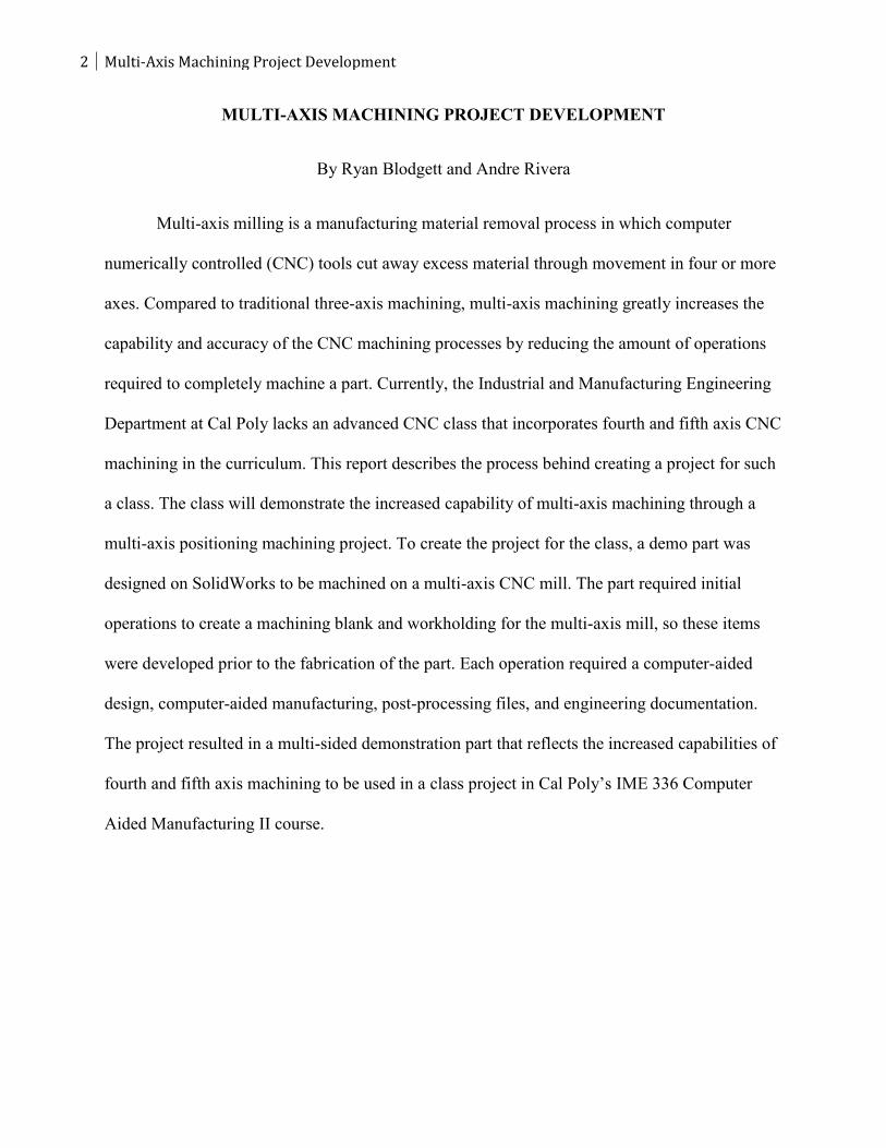
MULTI-AXIS MACHINING PROJECT DEVELOPMENT
By Ryan Blodgett and Andre Rivera
Multi-axis milling is a manufacturing material removal process in which computer
numerically controlled (CNC) tools cut away excess material through movement in four or more
axes. Compared to traditional three-axis machining, multi-axis machining greatly increases the
capability and accuracy of the CNC machining processes by reducing the amount of operations
required to completely machine a part. Currently, the Industrial and Manufacturing Engineering
Department at Cal Poly lacks an advanced CNC class that incorporates fourth and fifth axis CNC
machining in the curriculum. This report describes the process behind creating a project for such
a class. The class will demonstrate the increased capability of multi-axis machining through a
multi-axis positioning machining project. To create the project for the class, a demo part was
designed on SolidWorks to be machined on a multi-axis CNC mill. The part required initial
operations to create a machining blank and workholding for the multi-axis mill, so these items
were developed prior to the fabrication of the part. Each operation required a computer-aided
design, computer-aided manufacturing, post-processing files, and engineering documentation.
The project resulted in a multi-sided demonstration part that reflects the increased capabilities of
fourth and fifth axis machining to be used in a class project in Cal Poly’s IME 336 Computer
Aided Manufacturing II course.
3
3 of 70
ACKNOWLEDGMENTS
This project was completed with the help of Trian Georgeou, Ladd Caine, and Loren Sunding.
Without these individuals contributing their time, this project would not have gone as smoothly
as it did. Thank you for your contributions to the success of this project.
4 Multi-Axis Machining Project Development
TABLE OF CONTENTS
Introduction ……………………………………………………………………………….….6
Background ………………………………………………………….......................................8
Figure 1 – Stair Steps of CNC Machining…………………………………………….9
Figure 2 – Toolpath Generation on HSMWorks CAM Program (HSMWorks)……………..10
Figure 3 - Types of End Mills Used in Milling (HSMWorks)…………………….…12
Figure 4 - Six Degrees of Freedom of an Object (Boyle, Brown, Rong)………….…13
Figure 5 - Cal Poly’s Haas VF-2 CNC Mill………………………………………….20
Figure 6 - Cal Poly’s Haas T5C Rotary Table………………………………………..21
Design …………..…………………………………………………………………………….22
Figure 7 - CAD Renderings of the Demo Part ……………………………………………….24
Figure 8 - Cross Sectional View of the Mill Blank Design …………………………..26
Figure 9 - Soft Jaw Design Rendering ………………………………………………..27
Figure 10 - SolidWorks CAD Rendering of the Mill Fixture …………………………29
Methodology …………………………………………………………………………………..30
Figure 11 - Routing Sheet for the Demo Part ………………………………………….30
Table 1 – Cutting Speeds For Various Tool-Workpiece Combinations.....……………31
Table 2 – RPM Calculation ……………………………………………………………31
Table 3 – Tool Speeds and Feeds for the Demo Part Operation ………………………32
CAM ……………………………………………………………………………………………32
Figure 12 - (L to R) Soft Jaw Set Up, Machining, Outcome …………………….…….33
Figure 13 - Toolpaths For The First Lathe Operation …………………………………34
Figure 14 - Toolpaths For The Second Lathe Operation ………………………………34
Figure 15 - G54 Home Location for Fixture Milling Operation……………………….34
Figure 16 - Toolpaths for Fixture Milling Operation……………………………………35
Figure 17 - CAD Rendering of Mill Blank Inside Soft Jaws……………………………36
Figure 18 - Operation 1 for the Mill Blank………………………………………….…...37
Figure 19 - Milling Operation 2 for Mill Blank……………………………………….…38
Figure 20 - G54 Home Location for Demo Part…………………………………………39
Figure 21 - Coordinate System for Flat Pocket Operation…………………………..…..40
Figure 22 - Facing Passes, Milling Pocket, Spiral Finish Cut for Spherical Hole………41
Table 4 - Lathe Tool Insert Designation…………………………………..…………….41
5
5 of 70
Figure 23 - (L to R) Haas TL-1, Touching off the CNMG 432 in the Z Axis ……….…43
Figure 24 - (L to R): Renishaw OTS, Tool Offset Screen, Renishaw OMP…………..…44
Figure 25 – Aligning the Haas T5C……………………………………………………...45
Figure 26 - Setting Up The Haas T5C …………………………………………..………45
Figure 27 - Tooling For The Demo Part ………………………………………..……….46
Results………………………………………………………………..………………………….47
Figure 28 - Mill Fixture Defect ………………...…………………………………….....48
Figure 29 - Cutting The Mill Stock ……………………………………………………...49
Figure 30 - Chamfer Defect vs. Final Mill Blank ……………………………………….50
Figure 31 - Result of the Demo Part ………………………………………………….....50
Table 5 - Cost Per Part…………………………………………………………………...51
Conclusions……………………………………………………………………….......................51
Works Cited………………………………………………………………………......................53
APPENDICES
A. Drawings ……………………………………………………………….….............55
B. Routing Sheets……………………………………………………………….……....59
C. Operation Sheets………………………………………………………………..……64
6 Multi-Axis Machining Project Development
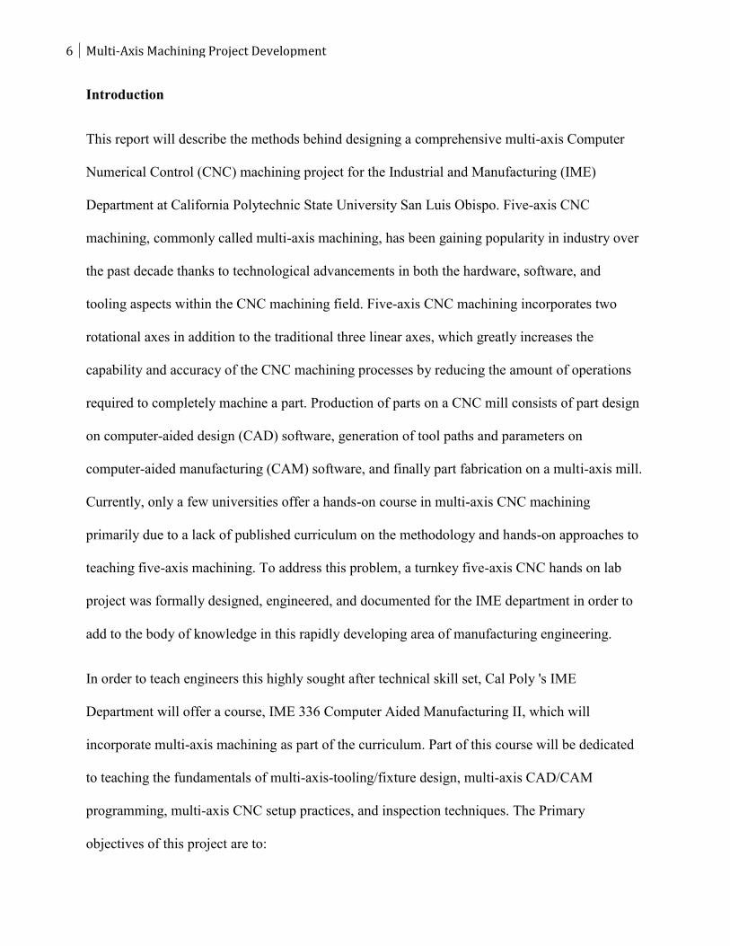
Introduction
This report will describe the methods behind designing a comprehensive multi-axis Computer
Numerical Control (CNC) machining project for the Industrial and Manufacturing (IME)
Department at California Polytechnic State University San Luis Obispo. Five-axis CNC
machining, commonly called multi-axis machining, has been gaining popularity in industry over
the past decade thanks to technological advancements in both the hardware, software, and
tooling aspects within the CNC machining field. Five-axis CNC machining incorporates two
rotational axes in addition to the traditional three linear axes, which greatly increases the
capability and accuracy of the CNC machining processes by reducing the amount of operations
required to completely machine a part. Production of parts on a CNC mill consists of part design
on computer-aided design (CAD) software, generation of tool paths and parameters on
computer-aided manufacturing (CAM) software, and finally part fabrication on a multi-axis mill.
Currently, only a few universities offer a hands-on course in multi-axis CNC machining
primarily due to a lack of published curriculum on the methodology and hands-on approaches to
teaching five-axis machining. To address this problem, a turnkey five-axis CNC hands on lab
project was formally designed, engineered, and documented for the IME department in order to
add to the body of knowledge in this rapidly developing area of manufacturing engineering.
In order to teach engineers this highly sought after technical skill set, Cal Poly 's IME
Department will offer a course, IME 336 Computer Aided Manufacturing II, which will
incorporate multi-axis machining as part of the curriculum. Part of this course will be dedicated
to teaching the fundamentals of multi-axis-tooling/fixture design, multi-axis CAD/CAM
programming, multi-axis CNC setup practices, and inspection techniques. The Primary
objectives of this project are to:
7
7 of 70
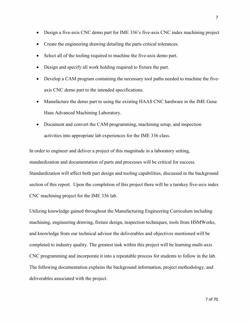
Design a five-axis CNC demo part for IME 336’s five-axis CNC index machining project
Create the engineering drawing detailing the parts critical tolerances.
Select all of the tooling required to machine the five-axis demo part.
Design and specify all work holding required to fixture the part.
Develop a CAM program containing the necessary tool paths needed to machine the five-
axis CNC demo part to the intended specifications.
Manufacture the demo part to using the existing HAAS CNC hardware in the IME Gene
Haas Advanced Machining Laboratory.
Document and convert the CAM programming, machining setup, and inspection
activities into appropriate lab experiences for the IME 336 class.
In order to engineer and deliver a project of this magnitude in a laboratory setting,
standardization and documentation of parts and processes will be critical for success.
Standardization will affect both part design and tooling capabilities, discussed in the background
section of this report. Upon the completion of this project there will be a turnkey five-axis index
CNC machining project for the IME 336 lab.
Utilizing knowledge gained throughout the Manufacturing Engineering Curriculum including
machining, engineering drawing, fixture design, inspection techniques, tools from HSMWorks,
and knowledge from our technical advisor the deliverables and objectives mentioned will be
completed to industry quality. The greatest task within this project will be learning multi-axis
CNC programming and incorporate it into a repeatable process for students to follow in the lab.
The following documentation explains the background information, project methodology, and
deliverables associated with the project.
8 Multi-Axis Machining Project Development
Background
Overview of Multi-axis machining
Multi-axis milling is a manufacturing material removal process in which computer numerically
controlled (CNC) tools cut away excess material through movement in four or more axes.
Computer numerically controlled systems are made up of three components: a program of
instructions, a machine control unit, and the processing equipment. Compared to traditional
three-axis machining, five axes are a combination of three linear axes (x, y, and z-axes) plus two
rotary axes (either a dual rotary axis, a rotary axis with a rotary table, or a compound rotary table)
that are capable of moving around a work-piece simultaneously (Bolton, Miller, Watts 5). For
this project we will be utilizing a table/table machine setup. This means that both rotary axes are
attached to the table. This machine configuration will determine the location of the part in the
computer aided manufacturing software. The benefits of multi-axis machining over three-axis
machining includes a reduction in machining time and manual labor, superior surface finish, and
the ability to manufacture more complex parts. However, this added capability brings a much
higher degree of complexity. There is a significant increase in level of intricacy from third to
fourth axis, compared to the jump from two to three axes (Zamora 493). The project in this
report describes the process of creating a four and a half axis positioning exercise that will
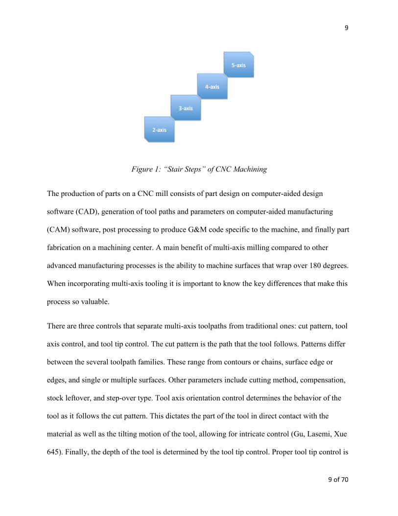
demonstrate the increased intricacy of the process. Figure 1 shows the increasing levels of CNC
machining, demonstrating that with each step comes improved levels of capability and part
complexity but also a decrease in cost and set up time.
9
9 of 70
Figure 1: “Stair Steps” of CNC Machining
The production of parts on a CNC mill consists of part design on computer-aided design
software (CAD), generation of tool paths and parameters on computer-aided manufacturing
(CAM) software, post processing to produce G&M code specific to the machine, and finally part
fabrication on a machining center. A main benefit of multi-axis milling compared to other
advanced manufacturing processes is the ability to machine surfaces that wrap over 180 degrees.
When incorporating multi-axis tooling it is important to know the key differences that make this
process so valuable.
There are three controls that separate multi-axis toolpaths from traditional ones: cut pattern, tool
axis control, and tool tip control. The cut pattern is the path that the tool follows. Patterns differ
between the several toolpath families. These range from contours or chains, surface edge or
edges, and single or multiple surfaces. Other parameters include cutting method, compensation,
stock leftover, and step-over type. Tool axis orientation control determines the behavior of the
tool as it follows the cut pattern. This dictates the part of the tool in direct contact with the
material as well as the tilting motion of the tool, allowing for intricate control (Gu, Lasemi, Xue
645). Finally, the depth of the tool is determined by the tool tip control. Proper tool tip control is
10 Multi-Axis Machining Project Development
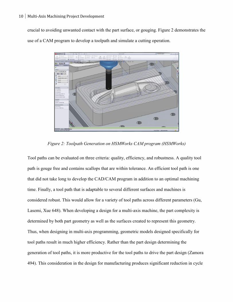
crucial to avoiding unwanted contact with the part surface, or gouging. Figure 2 demonstrates the
use of a CAM program to develop a toolpath and simulate a cutting operation.
Figure 2: Toolpath Generation on HSMWorks CAM program (HSMWorks)
Tool paths can be evaluated on three criteria: quality, efficiency, and robustness. A quality tool
path is gouge free and contains scallops that are within tolerance. An efficient tool path is one
that did not take long to develop the CAD/CAM program in addition to an optimal machining
time. Finally, a tool path that is adaptable to several different surfaces and machines is
considered robust. This would allow for a variety of tool paths across different parameters (Gu,
Lasemi, Xue 648). When developing a design for a multi-axis machine, the part complexity is
determined by both part geometry as well as the surfaces created to represent this geometry.
Thus, when designing in multi-axis programming, geometric models designed specifically for
tool paths result in much higher efficiency. Rather than the part design determining the
generation of tool paths, it is more productive for the tool paths to drive the part design (Zamora
494). This consideration in the design for manufacturing produces significant reduction in cycle
11
11 of 70
time and surface finish (Zamora 495). In development of this project, this principle will be
applied in the design of the demo part. Knowledge of the tooling capability and nature of the
toolpaths will be the main considerations when designing features.
Another important aspect of five-axis CAD/CAM programming is tool selection. The machine
does not automatically determine what tools should be used for the different tool paths, and
therefore there must careful consideration for specific cutters for specific jobs. There are several
different parameters to judge the effectiveness of a tool, which include tool life, manufacturing
cost, and required surface finish. These are all determined by the type, shape, and size of the tool
(Bassi, Bedi, Bolanos, Patel 655). Types of cutters for mills include slitting cutters, gear cutters,
and end mills. For the demo part, end mills will be used exclusively, which are the most common
types of cutter for five-axis milling. An end mill differs from a standard drill bit in its ability to
cut typically in all directions (however some are limited in drilling applications). Some types of
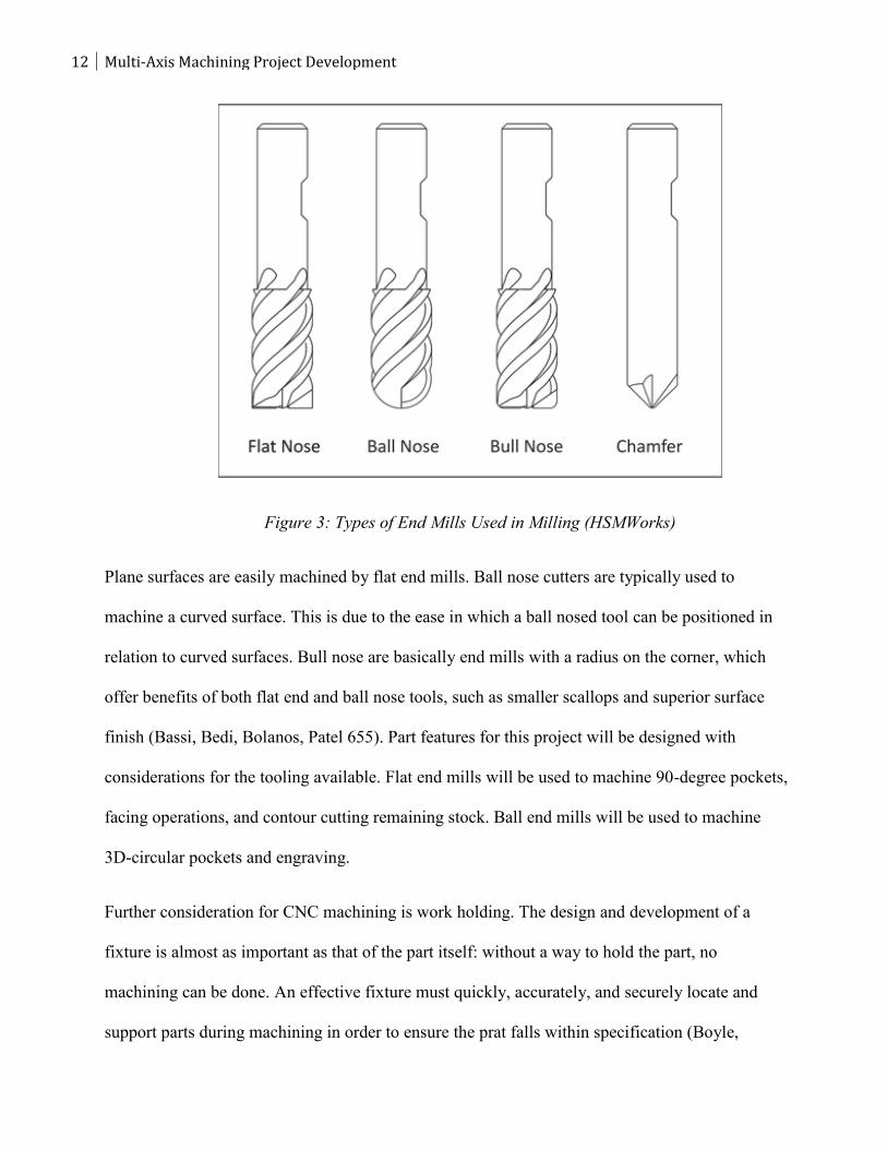
end mills include flat end, ball nose, bull nose and chamfer end mills, as shown in Figure 3.
12 Multi-Axis Machining Project Development
Figure 3: Types of End Mills Used in Milling (HSMWorks)
Plane surfaces are easily machined by flat end mills. Ball nose cutters are typically used to
machine a curved surface. This is due to the ease in which a ball nosed tool can be positioned in
relation to curved surfaces. Bull nose are basically end mills with a radius on the corner, which
offer benefits of both flat end and ball nose tools, such as smaller scallops and superior surface
finish (Bassi, Bedi, Bolanos, Patel 655). Part features for this project will be designed with
considerations for the tooling available. Flat end mills will be used to machine 90-degree pockets,
facing operations, and contour cutting remaining stock. Ball end mills will be used to machine
3D-circular pockets and engraving.
Further consideration for CNC machining is work holding. The design and development of a
fixture is almost as important as that of the part itself: without a way to hold the part, no
machining can be done. An effective fixture must quickly, accurately, and securely locate and
support parts during machining in order to ensure the prat falls within specification (Boyle,
13
13 of 70
Brown, Rong 1). In any competitive industry, the ability to rapidly meet these expectations for a
variety of high quality parts is invaluable. Costs associated with fixturing can account for up to
20 percent of the total manufacturing process (Boyle, Brown, Rong 2).
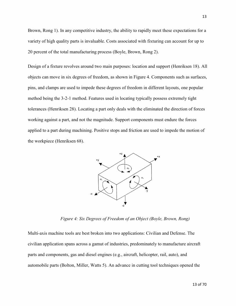
Design of a fixture revolves around two main purposes: location and support (Henriksen 18). All
objects can move in six degrees of freedom, as shown in Figure 4. Components such as surfaces,
pins, and clamps are used to impede these degrees of freedom in different layouts, one popular
method being the 3-2-1 method. Features used in locating typically possess extremely tight
tolerances (Henriksen 28). Locating a part only deals with the eliminated the direction of forces
working against a part, and not the magnitude. Support components must endure the forces
applied to a part during machining. Positive stops and friction are used to impede the motion of
the workpiece (Henriksen 68).
Figure 4: Six Degrees of Freedom of an Object (Boyle, Brown, Rong)
Multi-axis machine tools are best broken into two applications: Civilian and Defense. The
civilian application spans across a gamut of industries, predominately to manufacture aircraft
parts and components, gas and diesel engines (e.g., aircraft, helicopter, rail, auto), and
automobile parts (Bolton, Miller, Watts 5). An advance in cutting tool techniques opened the
14 Multi-Axis Machining Project Development
door for alloy steels (previously used in dies and moulds) to be used in the production of a
multitude of automotive components in addition to plastics (Logins and Torims 2). Other
industries that utilize multi-axis machining include medical, tool, industrial machinery, oil, and
manufacturing.
According to Department Of Defense’s Military Critical Technologies List (MCTL), modern
weapon systems require a variety of production equipment to manufacture necessary components
(Bolton, Miller, Watts 5). High precision manufacturing processes are necessary to fabricate a
range of parts including submarine and ship propellers (particularly quiet propellers), as well as
turbine and compressor blades to small parts for gyroscopes, engine parts, and even nuclear
weapons.
Effective application of five-axis machining alongside CAD/CAM software offers significant
improvements in part quality and productivity with savings in both time and cost. The
combination of tool path generation on CAD and simultaneous five-axis machining has become
one of the most flexible, productive, and complex manufacturing technologies available.
Simultaneous five-axis material removal allows machining of an entire part in a single set up
(Dimitrov & Saxer 2). This benefit greatly reduces the chances of operator error and accuracy
issues of multi-fixture machining because there is no stopping the machine to reposition the
workpiece or to continue cutting or grinding the piece on another machine (Bolton, Miller, Watts
5). Although the part described in this project will not be utilizing simultaneous five-axis
machining, it will demonstrate the increased capability of a four and a half axis index machining.
The part will be designed to show how a 3D part can be machined in it’s entirety in one
operation.
15
15 of 70
As an increasing number of industries utilize the benefits of multi-axis machining, the demand
for engineers and technicians with this particular skill set increases. However, few universities
across the U.S. teach the skills needed to design, tool, program, and machine multi-axis parts
(Zamora 4). The U.S. Department of Commerce’s Bureau of Industry and Security compiled a
technology assessment report on Five-Axis Simultaneous Control Machine Tools in July 2009,
and in the labor section of the report there was overwhelming evidence that skilled labor
shortage has not only affected companies buying multi-axis machining centers but also has
affected the producers as well. “While our current workload and prospective sales would justify
further investment in high-end machine tools, the lack of available skilled labor to operate the
new equipment has prevented further expansion,” stated one commercial end-user (Bolton,
Miller, Watts 38). This disparity forces companies to increase their lead times, production costs
and training costs. Less than 40 percent of companies partner with local and regional colleges as
well as technical schools that offer training programs, internships, and apprenticeships.
Nevertheless, more support for U.S. training programs needs to be developed to maintain a
skilled workforce and retain U.S. jobs (Bolton, Miller, Watts 38).
To help address this need, it is important to understand the demand for multi-axis machining
centers. In Figure 6 you can see that multi-axis machining centers were the most expensive
purchased by End-Users, the reason being that machine centers offer the most versatility. A
survey was compiled for end users to project their need for multi-axis machines. Results show
that demand for machining centers and mills will make up the most of machines bought. US
Government work drives a significant portion of the commercial demand for five axis machine
tools (Bolton, Miller, Watts 37). Most commercial end-users are contractors of the US
Government, and are more likely to purchase these machines. Similar to aggregate demand, mills
16 Multi-Axis Machining Project Development
and machining centers make up the largest portion of US Government demand by type (Bolton,
Miller, Watts 37). At the end of the report the Bureau of Industry and Security recommends that
the US Government identifies training proposals for educational institutions to address the
growing problem of a lack of skilled labor to design, build, and use machine tools (Bolton,
Miller, Watts 51). As civilian and military industries continue to increase their use on multi-axis
machine centers the demand for skilled engineers and operators needs to meet that demand in
order for this industry to stay at the forefront of technology.
Manufacturing engineering students in their third and fourth year at Cal Poly have a fundamental
understanding of various manufacturing methods, including 3-axis CNC machining, through
their previous courses. Our project will require the collective education gained from Cal Poly
coursework, and the development of a multi-axis project, or IME 336, relies on the following
courses to provide a solid background in manufacturing engineering principles
Graphics Communication and Modeling (IME 140) teaches students to computer-aided drafting
and modeling of solid parts, in addition to the basics of manufacturing tolerances. Students learn
how to form assemblies on CAD software.
Introduction to Design and Manufacturing (IME 144) builds upon these skills with hands-on
experience with conventional machining processing on manual lathes and mills. Students learn
about feeds and speeds for different tool and material types. Computer numerical control, Design
for Manufacturing (DFM) and Design for Assembly (DFA) strategies are first introduced to
students in this class, in addition to the basics of drafting. A basic background of manual
machining practices will prepare students for the programming, setup, and operation of CNC
machines.
17
17 of 70
From there, Cal Poly manufacturing engineering students enroll in Fundamentals of
Manufacturing Engineering (IME 330). Here, students learn to determine proper manufacturing
methods for different processes. Students gain experience setting up and operating processing
equipment, including the Haas CNC mill.
Students are then eligible to take Computer-Aided Manufacturing I (IME 335), where they use
CAD/CAM software to communicate design information to the manufacturing equipment. IME
335 is the first class students spend their main focus on all the aspects of CNC machining, and
gain experience programming, setting up, and operation on lathes and mills. However, the class
is limited in its scope: only three-axis machining is touched upon in the curriculum. Students are
not exposed to the added complexity and functionality of 4th and 5th axis machining.
Another class relevant to this completion of this project and to the practicality of a multi-axis
curriculum is IME 450, or Manufacturing Process and Tool Engineering. Students learn
engineering design of fixtures and tools used in manufacturing processes, and how to properly
design and produce a work-holding device to locate and secure the part. Our project requires
skills obtained from all these classes. Looking back at our objectives, each will be accomplished
through utilization of our education here at Cal Poly.
Another important variable is material removal rate, or the total volume of material removed per
machining time. Students learn the impact that each of these parameters have on the machine,
tool, and part cost. Introductory courses also initiate students in the use of computer-aided design.
Design for Manufacturing (DFM) and Design for Assembly (DFA) are two important disciplines
that are taught through the Cal Poly Manufacturing Curriculum. These ideas are touched upon in
multiple classes. However, in our project, DFA will not be applied as extensively as DFM
18 Multi-Axis Machining Project Development
because we are not developing a series of parts for assembly. The Design for Manufacturing
considerations for our project will be touched upon in the Design section of our project.
The Computer-Aided Manufacturing I course is the first experience Cal Poly manufacturing
students get taking part designs from SolidWorks CAD, developing tool paths using Masercam
or HSMWorks (CAM), and generating the necessary G&M code. However, the course is limited
to 3-axis machining only. An advanced computer-aided manufacturing class would help expand
students previously acquired skills, putting them to use developing and producing parts on a five-
axis CNC mill.
When creating a curriculum it is important to benchmark other institutions around the country. It
was discovered that only a few universities offer a hands-on course in multi-axis CNC machining
primarily due to a lack of published curriculum on the methodology and hands-on approach to
teaching five-axis simultaneous machining. The articles found will serve as the benchmark for
this project that we will meet and exceed.
Perhaps the most comprehensive article was from Arizona State University. The article explains
the importance of having a knowledgeable background of material removal processes in order to
progress into multi-axis machining. There are two courses that lay down the fundamentals of 2
and 3-axis milling as well as manual and CAD/CAM programming and troubleshooting. The
teaching materials developed mimic those in many textbooks where the content is wrapped
around projects or parts. (Biekert,Danielson, Zamora 4)
This article explains the importance of Design for Manufacture and how it is critical for
designing complex geometric shapes and parts. Geometric model complexity is driven by part
19
19 of 70
complexity. However, in multi-axis CNC programming, complexity is driven by both geometry
and the surfaces generated to represent the parts geometry. (Biekert,Danielson, Zamora 2)
Having a general sense of what tooling will be available, surface finish desired, and overall
quality of the part will greatly influence the design aspect of a project.
Another key insight is providing students with commercially available software and hardware
(Biekert, Danielson, Zamora 3) and within the past decade there has been a profound
improvement in CAM and post processing software of which Cal Poly is fortunate to have
thorough industry support. Lastly, Teaching multi-axis machining is a progressive process
(Biekert,Danielson, Zamora 3). It is important to present students with current trends, and
problems facing manufacturing and relating that to multi-axis machining.
South Dakota State University taught a course on multi-axis machining with an emphasis on
simulation software. Collision-avoidance and geometric-error detection are critical issues for
multi-axis CNC machining (Qian 1). CNC verification software allows students to accurately
check their parameters and tooling choices for optimal performance without using expendable
materials. Optimization of these parameters requires a strong understanding, which is highly
sought after in industry for time and cost savings.
S.D.S.U. divided up their labs into seven projects. It is important for students to understand how
to set up the machine they are going to run, with the students’ knowledge of the Haas VF2 from
IME 335, we can build upon that knowledge to utilize multi-axis machining capabilities. Their
final project involved the students designing turbo blades to be machined, but only could
simulate operations due to a lack of multi-axis CAM software. Although it is important to
understand the fundamentals of design for manufacture, the students gain much more when they
20 Multi-Axis Machining Project Development
apply skill to physically set up and machine a part. This project will build upon both of these
universities multi-axis courses to be one of the most comprehensive courses available, to do that
it is important to have support from industry leaders.
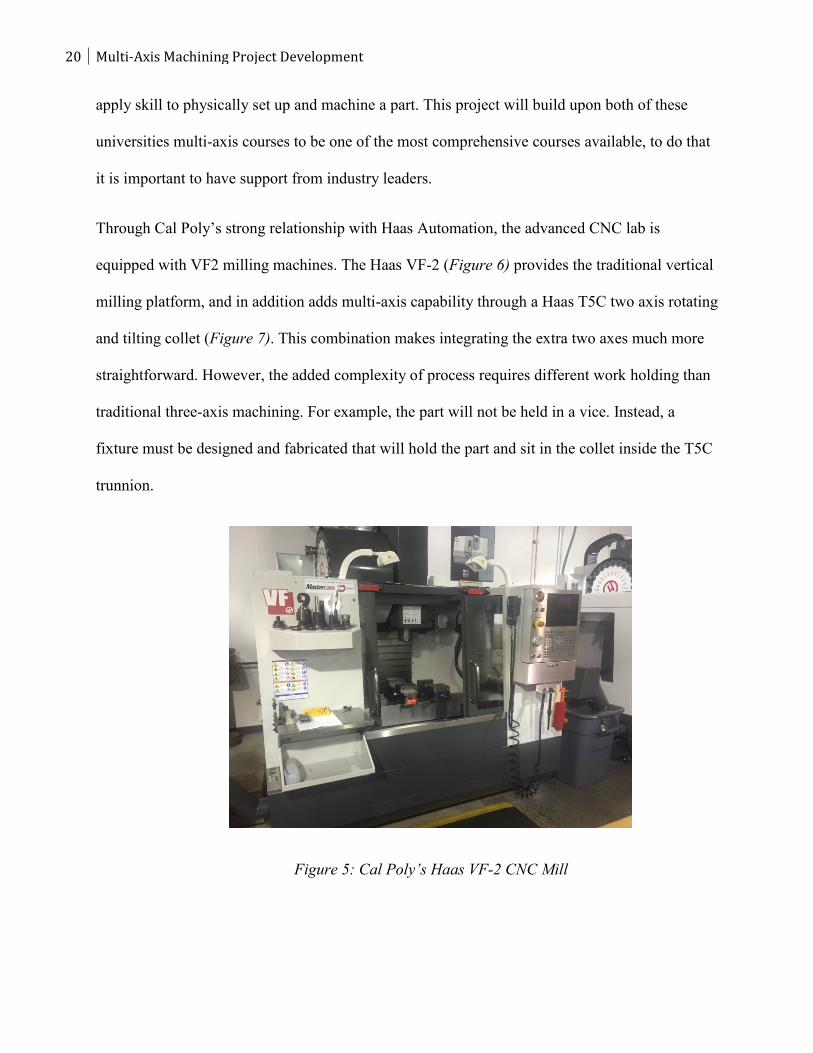
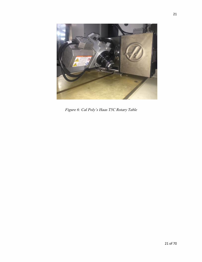
Through Cal Poly’s strong relationship with Haas Automation, the advanced CNC lab is
equipped with VF2 milling machines. The Haas VF-2 (Figure 6) provides the traditional vertical
milling platform, and in addition adds multi-axis capability through a Haas T5C two axis rotating
and tilting collet (Figure 7). This combination makes integrating the extra two axes much more
straightforward. However, the added complexity of process requires different work holding than
traditional three-axis machining. For example, the part will not be held in a vice. Instead, a
fixture must be designed and fabricated that will hold the part and sit in the collet inside the T5C
trunnion.
Figure 5: Cal Poly’s Haas VF-2 CNC Mill
21
21 of 70
Figure 6: Cal Poly’s Haas T5C Rotary Table
22 Multi-Axis Machining Project Development
Design
This section of the report describes in detail the process of designing the multi-axis index
machining demo part and work-holding. The design of a project for an advanced CNC
Machining course incorporates many of the concepts learned during the Manufacturing
Engineering undergraduate prerequisite courses. The objective was to design a demo part that
had to have a minimum of five sides machined in one work holding step. This will demonstrate
the increased capability of multi-axis CNC index machine operations. It must also include all of
the fixtures necessary to machine the blanks and final part. To accomplish this, having a
thorough understanding of design for manufacture (DFM) was critical. One of the concepts used
is the minimum number of parts (MNP) theory because it is an effective way to optimize the
manufacturing process, and in this case, stick to time constraints that the lab will have with 24
students in it. Furthermore, having the least number of components possible means fewer
manufacturing and assembly steps, lower cost, better quality, simpler inspection requirements,
and fewer design/part revision tracking all of which is extremely important in a manufacturing
setting and to this project. Other DFM techniques used for this project include use of concurrent
engineering, standardized materials and tooling.
Demo Part Design
Before coming up with the initial design we chose to use 6061-T6 aluminum as the demo part’s
material due to 6061-T6 being one of the most common grades of aluminum, having good
machinability characteristics, being readily available at a low cost. Next, we decided to design
the part based off of a 3.0” round bar stock size. Larger stock would result in increased
machining time and possibly not fit on the T5C rotary table while smaller stock would require
23
23 of 70
smaller tools to be used during this project and this would result in longer machine time. With
the alloy and material size chosen, we started to design the multi axis part.
Given the freedom to design the demo part, it is important to incorporate various CNC
machining features to showcase the increased capability of multi-axis machining. We wanted to
have features at angles that were not at perpendicular or parallel to other features. This type of
part geometry would usually require dedicated fixtures to hold the part during multiple
machining operations whereas we were going to machine all of the features using one work
holding step. Other important design considerations were machinability of the features and
complexity of the toolpaths as this project will be used for educational purposes.
To create the initial design, the computer aided design (CAD) software SolidWorks was used to
create a sold model. The first multi-axis geometry created was a 45 degree surface that was
duplicated around the part using the circular pattern tool in increments of 120 degrees this will
allow the A and B axis on the machine tool to be tilted and machine three different distinct
features on these surfaces 360 degrees around the part. An engraving of “CAL POLY
MANUFACTURING ENGINEERING” was placed on the first 45 degree surface. Next, a
spherical hole was created with .125” and .375” fillets due to DFM principles described earlier in
the report. This feature required a ball end mill and 3-axis toolpaths to achieve the desired
surface finish. This gives students an opportunity to create 3-axis CNC toolpaths on the multi-
axis part. Finally, the last 45 degree surface contained a traditional 2-axis pocket. After the three
45 degree surfaces were created a flat surface was made on the side of the part and duplicated at
120 degrees round the part. This flat surface contained a circular protrusion with a ¼”-20 tapped
hole in the center. These features allow the students to index the part to create the surfaces as
well as use canned cycles for drilling and tapping holes on the CNC mill. All of the features on
24 Multi-Axis Machining Project Development
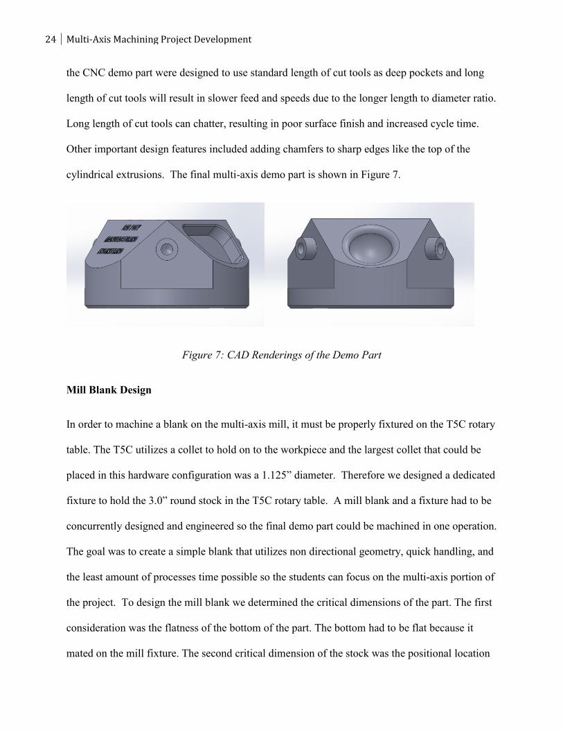
the CNC demo part were designed to use standard length of cut tools as deep pockets and long
length of cut tools will result in slower feed and speeds due to the longer length to diameter ratio.
Long length of cut tools can chatter, resulting in poor surface finish and increased cycle time.
Other important design features included adding chamfers to sharp edges like the top of the
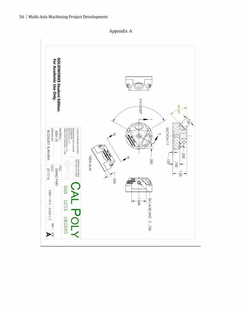
cylindrical extrusions. The final multi-axis demo part is shown in Figure 7.
Figure 7: CAD Renderings of the Demo Part
Mill Blank Design
In order to machine a blank on the multi-axis mill, it must be properly fixtured on the T5C rotary
table. The T5C utilizes a collet to hold on to the workpiece and the largest collet that could be
placed in this hardware configuration was a 1.125” diameter. Therefore we designed a dedicated
fixture to hold the 3.0” round stock in the T5C rotary table. A mill blank and a fixture had to be
concurrently designed and engineered so the final demo part could be machined in one operation.
The goal was to create a simple blank that utilizes non directional geometry, quick handling, and
the least amount of processes time possible so the students can focus on the multi-axis portion of
the project. To design the mill blank we determined the critical dimensions of the part. The first
consideration was the flatness of the bottom of the part. The bottom had to be flat because it
mated on the mill fixture. The second critical dimension of the stock was the positional location
25
25 of 70
of the through hole where the socket head cap screw holds the part on the fixture. The third
critical dimension was the location of the locating pin hole relative to the center hole. To
determine each hole size a standard cap screw size was selected that would properly fit the part
and provide sufficient clamping force to withstand the machining forces. Continuing with DFM
practices, we determined a standard ¼”-20 x 1” coarse thread socket head cap screw would
satisfy these constraints. The benefit of choosing a coarse thread over fine thread was the
durability and resistance to stripping due to there being more material between each thread. This
is ideal for running a large batch size, i.e. when students are using the fixture repeatedly in a
laboratory setting. The top counterbore diameter was designed at a nominal .500” because the
head of the screw is at maximum material condition (MMC) was found to be .438” and the depth
was also .500” to make sure that the cap screw sits underneath the surface of the part during
machining. The thru hole was sized to .257”, which corresponds to a size F drill for clearance of
the threaded fastener’s body. The third center hole at the bottom of the blank is used for mating
with the fixture and was designed to have an MMC diameter of .950” and least material
condition (LMC) of .955”, this ensures there will always be a clearance fit when the fixture and
mill blank are mated together during machining. This hole at the bottom of the blank locates the
blank on the fixture and removes the linear movement about the X and Y axes. The last feature
on the mill blank was the locating pin hole to accommodate the .250” down pin on the fixture.
This critical feature allows for quick and simple orientation and location of the blank on the
fixture and will be explained in greater detail when discussing the design for the mill fixture.
Because this is a critical feature a tight tolerance of .251” at MMC with an additional tolerance
of .256” at LMC to ensure the locating pin will have a clearance fit with the fixture pin. Once all
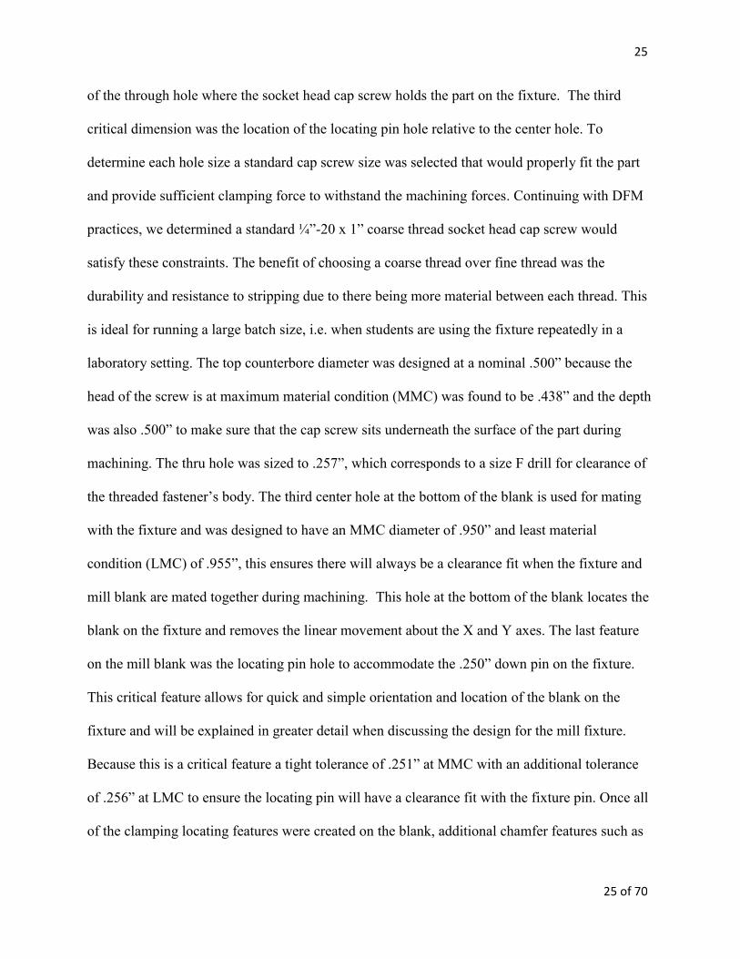
of the clamping locating features were created on the blank, additional chamfer features such as
26 Multi-Axis Machining Project Development
chamfers were added to soften edges of the part and allow the mating edges to have a better fit
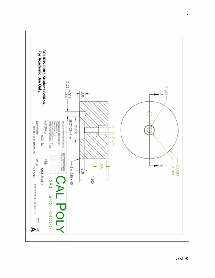
between parts. Figure 8 shows the cross sectional view of the cylindrical mill blank design.
Figure 8: Cross Sectional View of the Mill Blank Design
Fixture Design
Fixtures (work-holding devices) are a key component to any manufacturing process. The three
main functional requirements in a fixture are locating, holding, and supporting workpieces
during manufacturing operations. Fixtures provide a way to repeatedly align and reference a
cutting tool to the workpiece as well as orient the part to specific surfaces or datums. When
designing a fixture there were four important requirements were taken into consideration. The
material type was taken into account, the ease of installing/removing the workpiece, the
clearance of the toolpaths, and not marring the workpiece’s finish. Furthermore, the fixture had
to be able to withstand the forces during the repetitive machining process. Cumulative
allowances were also taken into account with respect to mill blank’s tolerances to ensure the
blank would always fit onto the fixture. Finally, we tried to design the fixture so the direct tool
27
27 of 70
forces were oriented towards the clamping. More information about the specifics of this
project’s soft jaw design and multi-axis fixture design can be found in the subsequent sections.
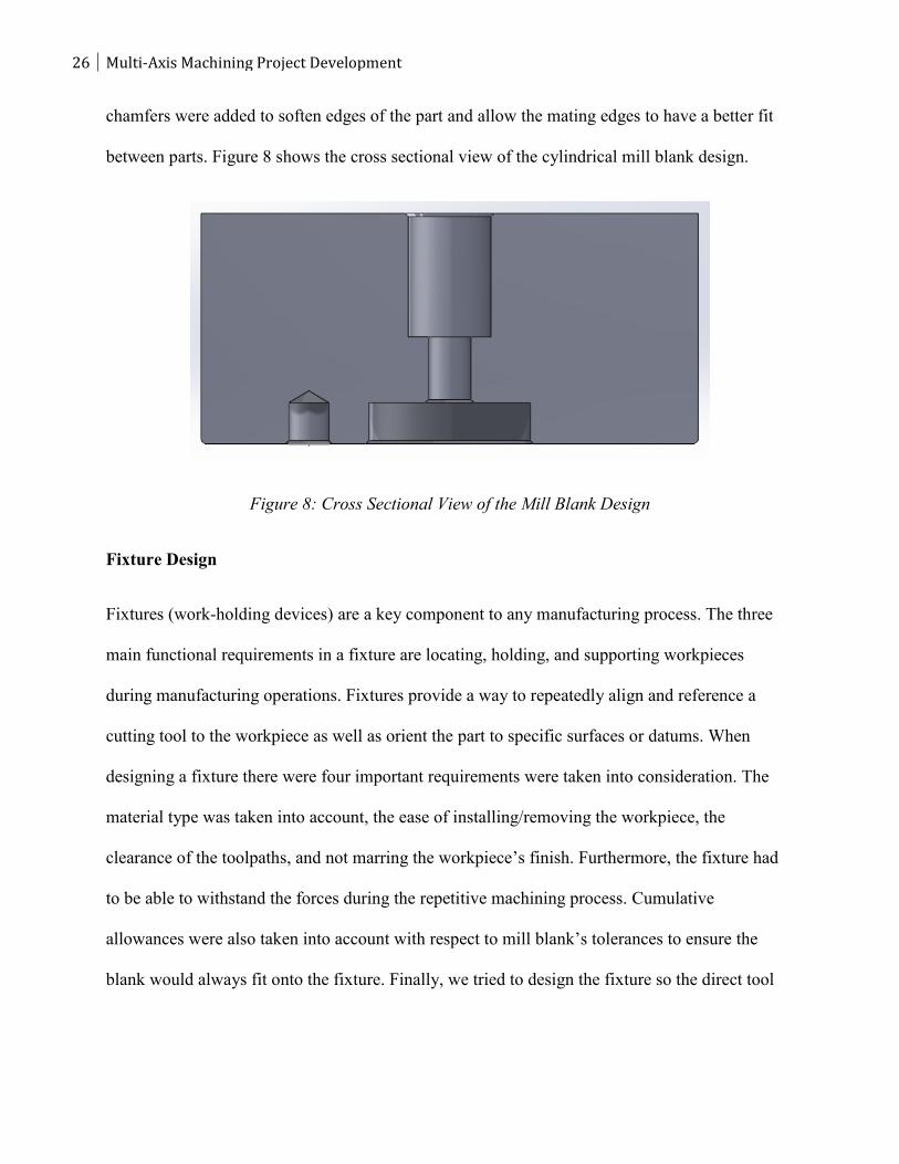
Soft Jaw Design
Due to the cylindrical bar stock used for the mill blank, a pair of soft jaw was designed to
perform all two of the machining operations required to create the mill blank. Soft jaws are a
common type of fixture used in CNC applications to hold an irregularly shaped workpiece in a
machine vise. Soft jaws are typically made of a softer metal compared to the hardened steel vise
jaws in order to be easily machined and reduce damage to the workpiece. The quickest and most
repeatable way to locate and hold the workpiece was to create a 3” diameter pocket out of 6061-
T6 jaws. We chose 6061-T6 because the low machining forces do not require anything tougher,
and it is the same material as the mill blank. The depth of the pocket was machined to .400” deep
in order to securely hold and support the workpiece as well as provide enough clearance for each
toolpath. Part orientation for this process is not of concern as it is a cylinder, which decreases
time to install and remove the workpiece. Figure 9 shows the soft jaw design from SolidWorks.
Figure 9: Soft Jaw Design Rendering
28 Multi-Axis Machining Project Development
Mill Fixture Design
For the mill fixture, a stronger and tougher material was needed due to the forces the part would
be subjected to when machining. It is good practice to utilize a stronger and tougher material for
the fixture design compared to the workpiece material being cut for rigidity and the life cycle of
the fixture. 316 series stainless steel was chosen for this material as it met all of the above
criteria and has excellent corrosion resistance so it will not rust overtime in the lab. 316 will
ensure that the fixture will hold up to repeated cycles and securely hold the part throughout the
duration of the IME 335 multi-axis lab project.
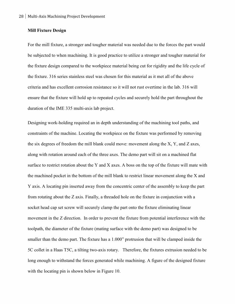
Designing work-holding required an in depth understanding of the machining tool paths, and
constraints of the machine. Locating the workpiece on the fixture was performed by removing
the six degrees of freedom the mill blank could move: movement along the X, Y, and Z axes,
along with rotation around each of the three axes. The demo part will sit on a machined flat
surface to restrict rotation about the Y and X axes. A boss on the top of the fixture will mate with
the machined pocket in the bottom of the mill blank to restrict linear movement along the X and
Y axis. A locating pin inserted away from the concentric center of the assembly to keep the part
from rotating about the Z axis. Finally, a threaded hole on the fixture in conjunction with a
socket head cap set screw will securely clamp the part onto the fixture eliminating linear
movement in the Z direction. In order to prevent the fixture from potential interference with the
toolpath, the diameter of the fixture (mating surface with the demo part) was designed to be
smaller than the demo part. The fixture has a 1.000” protrusion that will be clamped inside the
5C collet in a Haas T5C, a tilting two-axis rotary. Therefore, the fixtures extrusion needed to be
long enough to withstand the forces generated while machining. A figure of the designed fixture
with the locating pin is shown below in Figure 10.
29
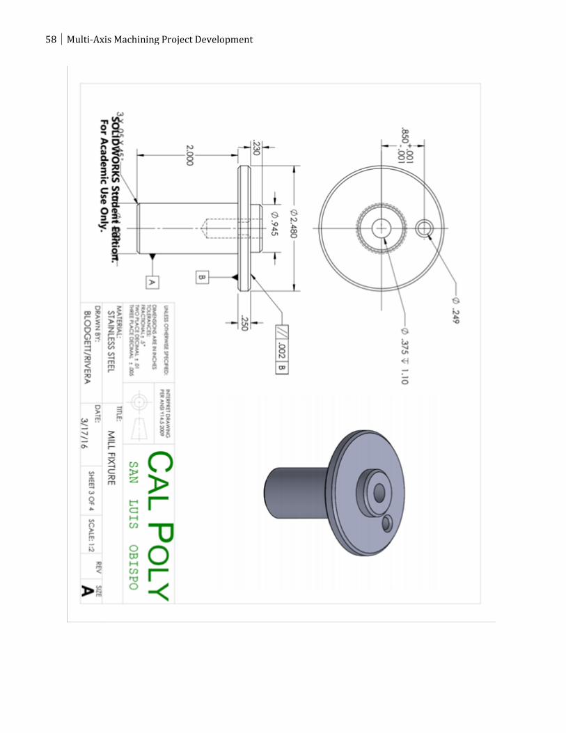
29 of 70
Figure 10: SolidWorks CAD Rendering of the Mill Fixture
After completing the solid model designs of the multi-axis part, blank, and fixture in
SolidWorks, engineering drawings were created. Drawings are critical for communicating
specific design requirements and tolerances consistently between the design engineers and the
manufacturing engineers, and the manufacturing technicians who manufacture the part. Because
every physical part varies from the drawing due to variables within the manufacturing process, it
was important to specify how much each feature could deviate from the theoretical exact
geometry. Geometric Dimensioning and Tolerancing (GD&T) was utilized to geometrically
tolerance critical features geometry and communicate the design intent. GD&T was used to
define a reference coordinate systems (datums) are to be used to ensure consistency between
design, manufacturing, and inspection phases. All of the drawings are shown in appendix A in
this report.
30 Multi-Axis Machining Project Development
Methodology
With the completion of each part and fixture design the next step was to plan out how to actually
make each part. The best way to do this was to concurrently create routings and toolpaths.
SolidWorks has integrated computer aided manufacturing (CAM) software called HSMWorks
that supports generating multi-axis toolpaths. There is a simulation function in the program to
view the toolpaths created to verify important machining parameters. This saved quite a bit of
time in routing creation and operation planning because trial and error was done using the
simulation models instead of physical parts. This allowed us to make quick changes within the
CAM program and update the manufacturing documentation without having to physically
rework parts.
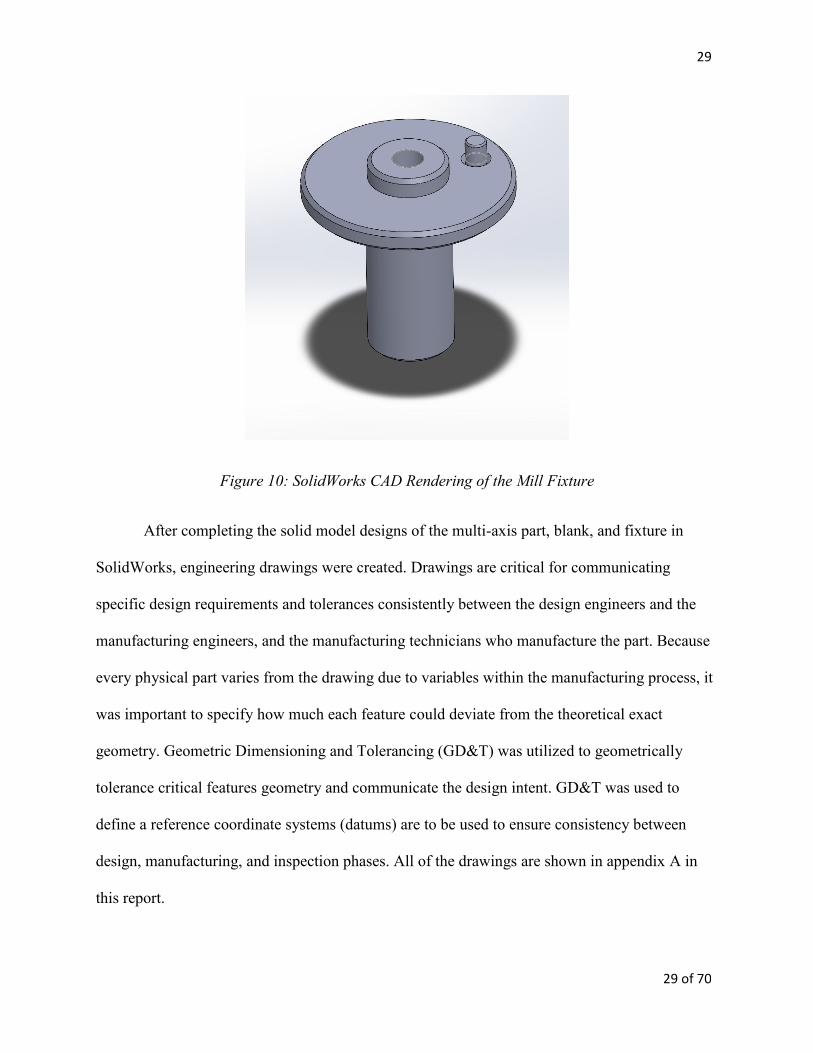
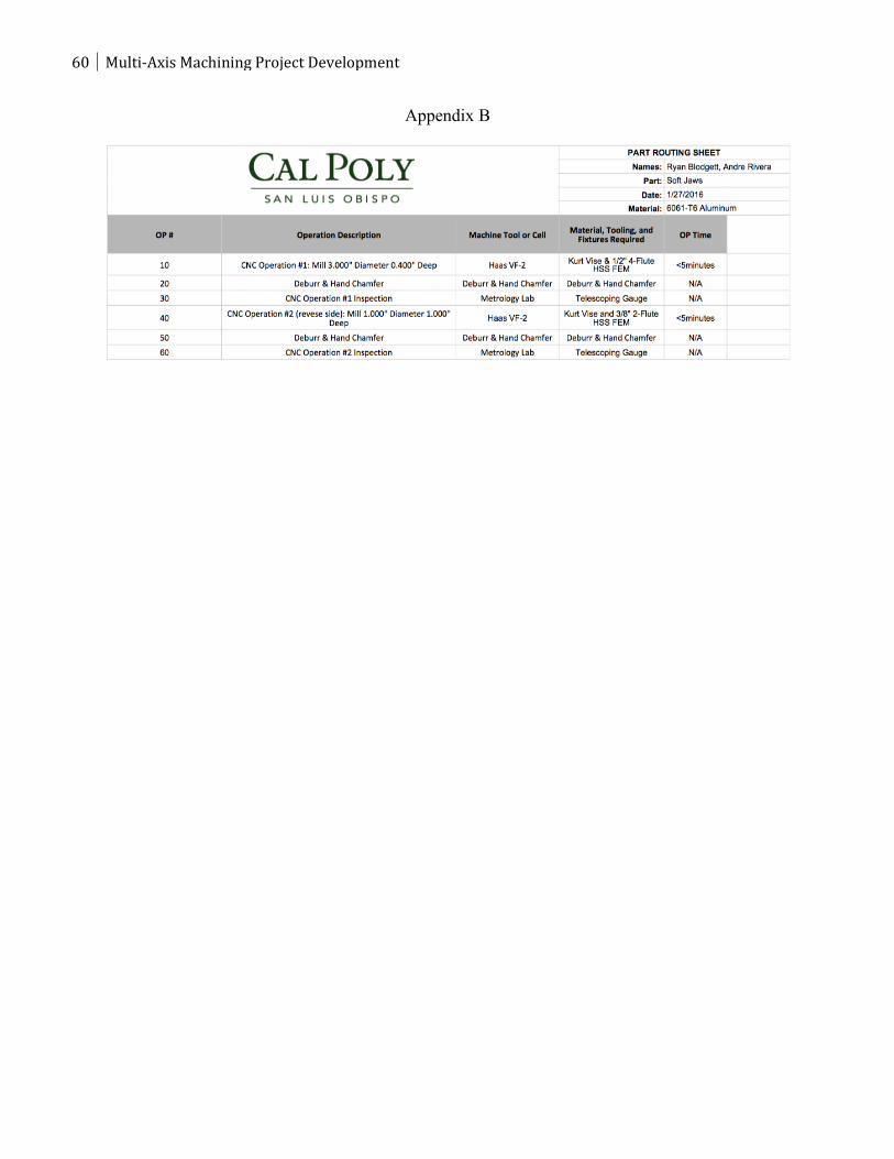
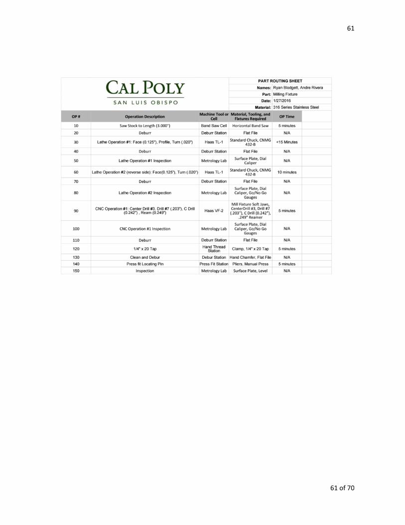
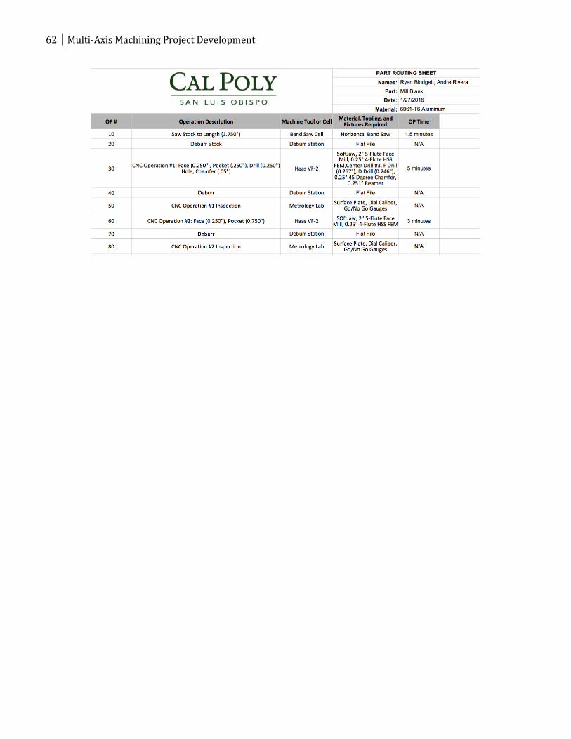
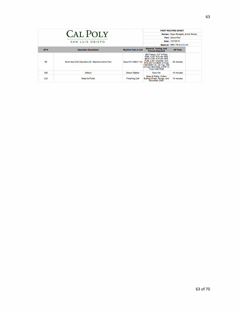
Routing sheets were created for all four parts that list each manufacturing operation in
order. A sample screenshot of a manufacturing routing is seen below in Figure 11 and the full
routings are shown in Appendix B in this report. Routing sheets are used to document the
required steps in the manufacturing process and allow students working on this lab project to
understand all of the steps needed to create the part from start to finish.
Figure 11: Routing Sheet for the Demo Part
31
31 of 70
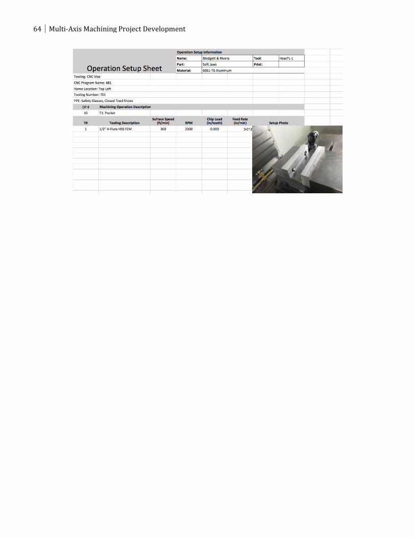
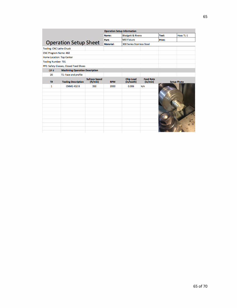
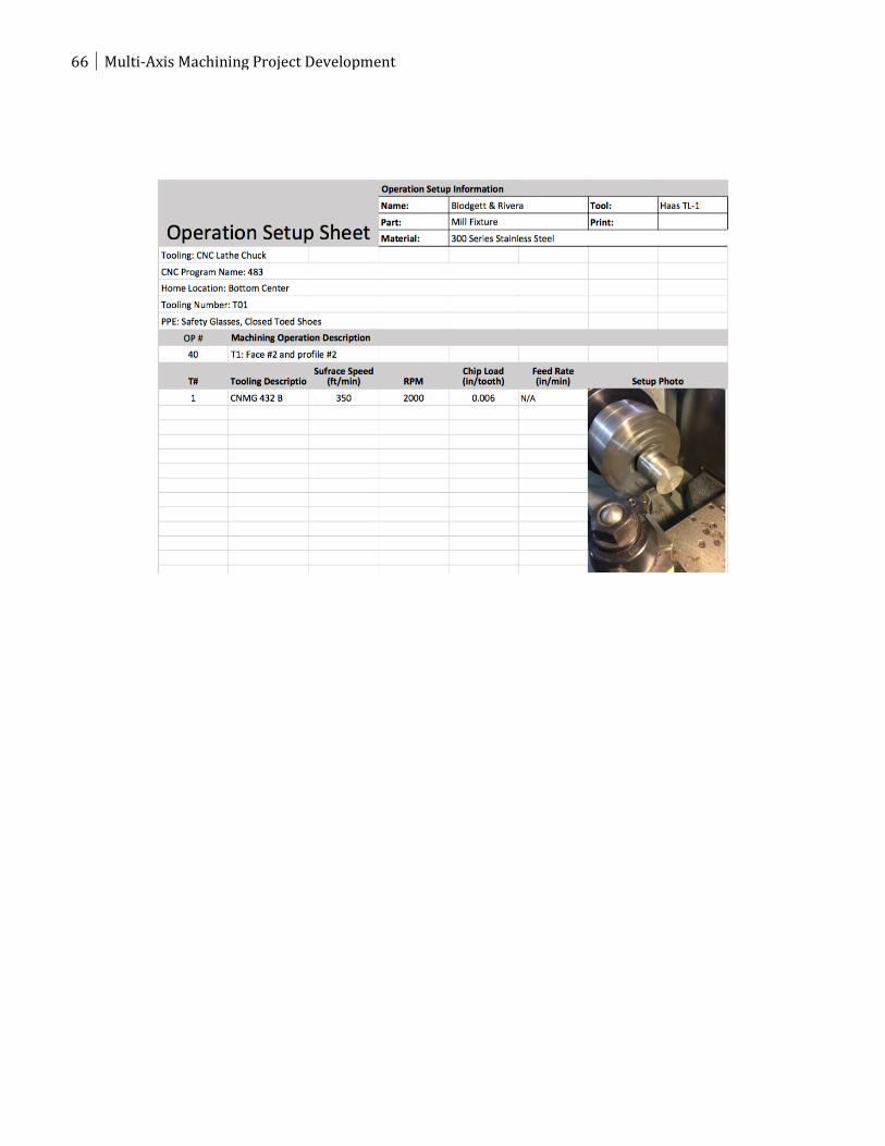
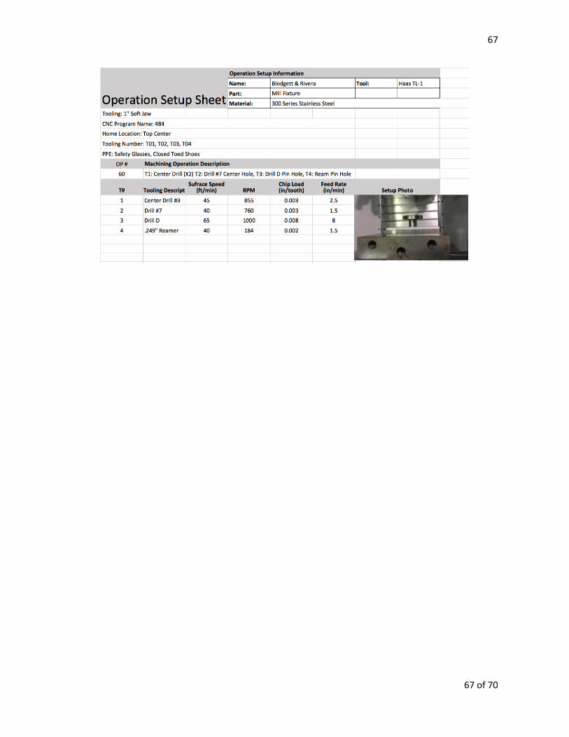
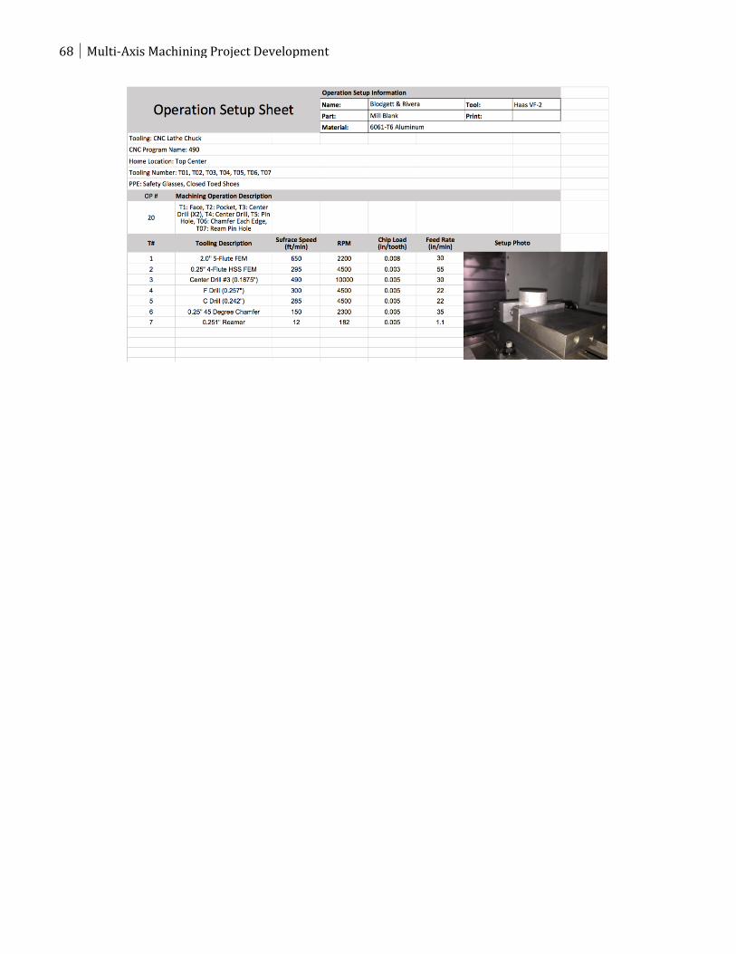
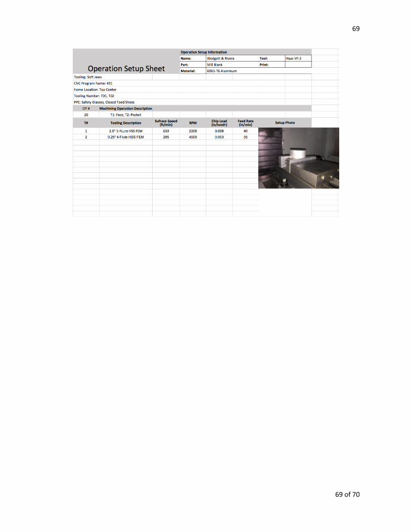
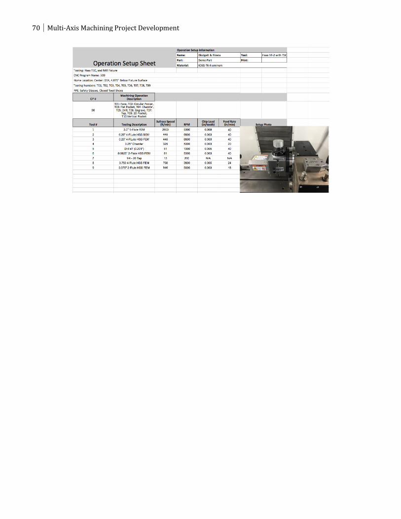
From the routing sheet, individual operation sheets were created for each machining step
specifying everything needed to set up and perform the job. The top of the sheet includes the
machine, program number, home location center, tool numbers, and personal protective
equipment (PPE) required for the operation. The rest of the sheet includes the operation number
and the description of the tool path for each tool. A table of each tool number, description of the
tool, surface speed, revolutions per minute (RPM), chip load in inches per tooth (ipt), and feed
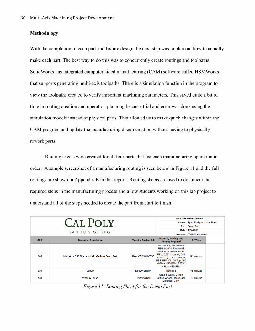
rate in inches per minute (ipm) is also provided on this document. The table below shows
common cutting speeds for various materials that have been taught in previous manufacturing
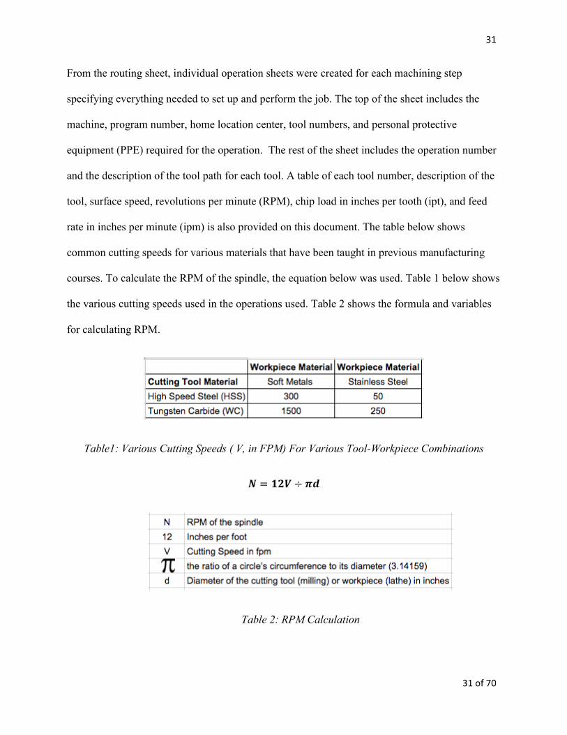
courses. To calculate the RPM of the spindle, the equation below was used. Table 1 below shows
the various cutting speeds used in the operations used. Table 2 shows the formula and variables
for calculating RPM.
Table1: Various Cutting Speeds ( V, in FPM) For Various Tool-Workpiece Combinations
𝑵 = 𝟏𝟐𝑽 ÷ 𝝅𝒅
Table 2: RPM Calculation
32 Multi-Axis Machining Project Development
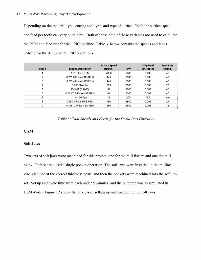
Depending on the material type, cutting tool type, and type of surface finish the surface speed
and feed per tooth can vary quite a bit. Both of these both of these variables are used to calculate
the RPM and feed rate for the CNC machine. Table 3. below contains the speeds and feeds
utilized for the demo part’s CNC operations.
Table 3: Tool Speeds and Feeds for the Demo Part Operation
CAM
Soft Jaws
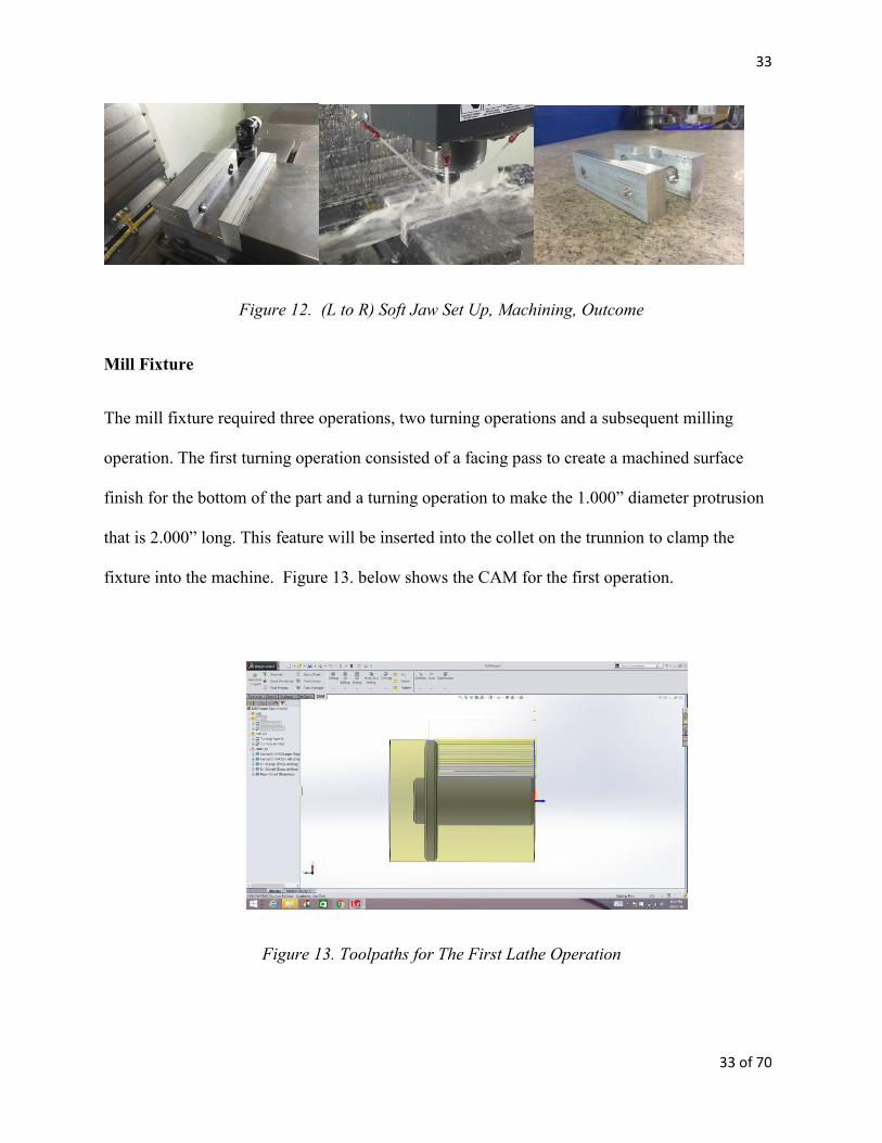
Two sets of soft jaws were machined for this project, one for the mill fixture and one the mill
blank. Each set required a single pocket operation. The soft jaws were installed in the milling
vise, clamped at the correct thickness apart, and then the pockets were machined into the soft jaw
set. Set up and cycle time were each under 5 minutes, and the outcome was as simulated in
HSMWorks. Figure 12 shows the process of setting up and machining the soft jaws.
33
33 of 70
Figure 12. (L to R) Soft Jaw Set Up, Machining, Outcome
Mill Fixture
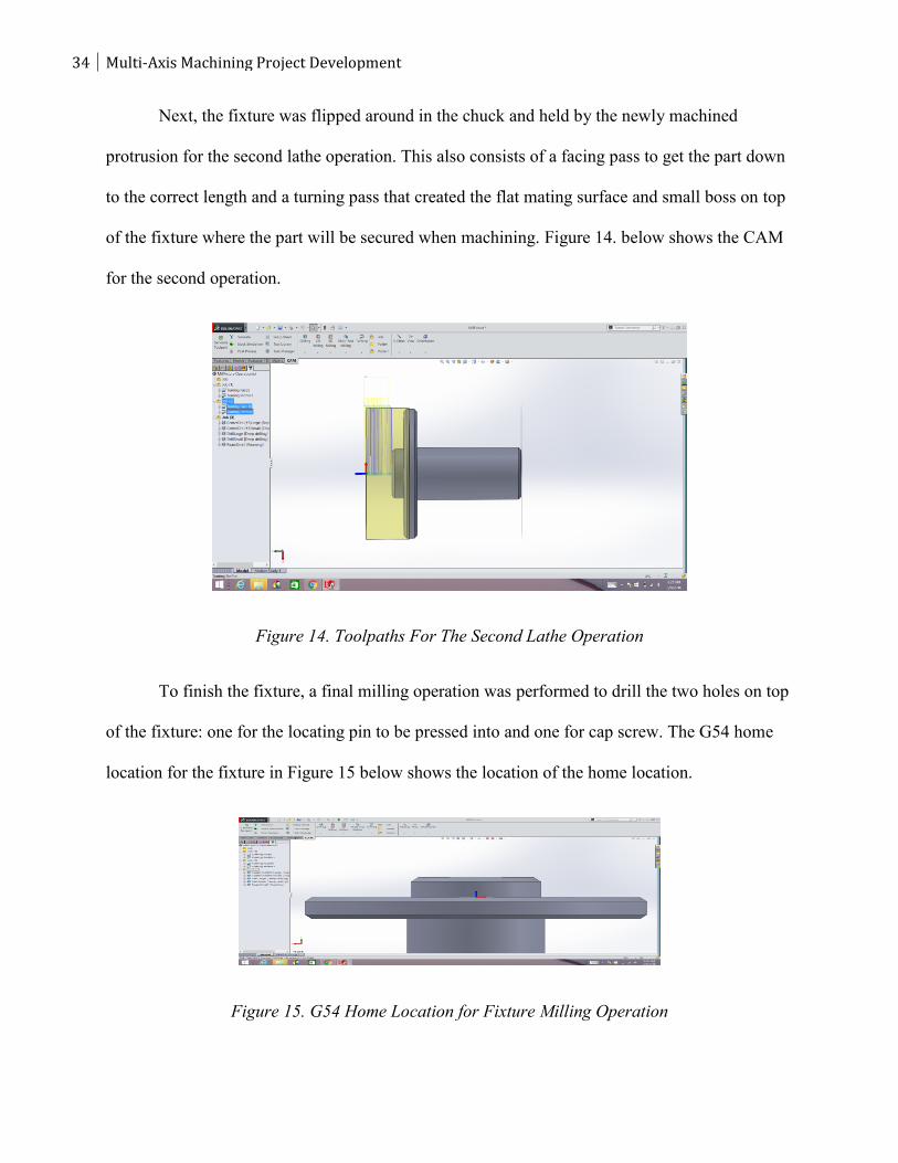
The mill fixture required three operations, two turning operations and a subsequent milling
operation. The first turning operation consisted of a facing pass to create a machined surface
finish for the bottom of the part and a turning operation to make the 1.000” diameter protrusion
that is 2.000” long. This feature will be inserted into the collet on the trunnion to clamp the
fixture into the machine. Figure 13. below shows the CAM for the first operation.
Figure 13. Toolpaths for The First Lathe Operation
34 Multi-Axis Machining Project Development
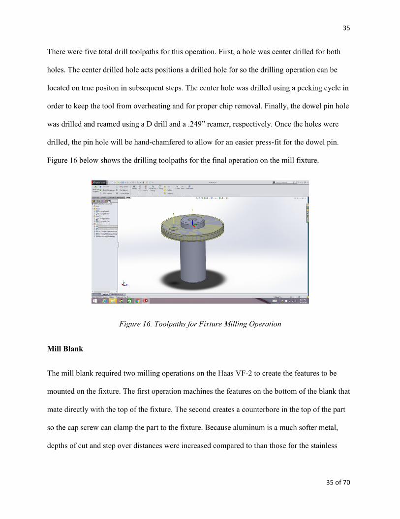
Next, the fixture was flipped around in the chuck and held by the newly machined
protrusion for the second lathe operation. This also consists of a facing pass to get the part down
to the correct length and a turning pass that created the flat mating surface and small boss on top
of the fixture where the part will be secured when machining. Figure 14. below shows the CAM
for the second operation.
Figure 14. Toolpaths For The Second Lathe Operation
To finish the fixture, a final milling operation was performed to drill the two holes on top
of the fixture: one for the locating pin to be pressed into and one for cap screw. The G54 home
location for the fixture in Figure 15 below shows the location of the home location.
Figure 15. G54 Home Location for Fixture Milling Operation
35
35 of 70
There were five total drill toolpaths for this operation. First, a hole was center drilled for both
holes. The center drilled hole acts positions a drilled hole for so the drilling operation can be
located on true positon in subsequent steps. The center hole was drilled using a pecking cycle in
order to keep the tool from overheating and for proper chip removal. Finally, the dowel pin hole
was drilled and reamed using a D drill and a .249” reamer, respectively. Once the holes were
drilled, the pin hole will be hand-chamfered to allow for an easier press-fit for the dowel pin.
Figure 16 below shows the drilling toolpaths for the final operation on the mill fixture.
Figure 16. Toolpaths for Fixture Milling Operation
Mill Blank
The mill blank required two milling operations on the Haas VF-2 to create the features to be
mounted on the fixture. The first operation machines the features on the bottom of the blank that
mate directly with the top of the fixture. The second creates a counterbore in the top of the part
so the cap screw can clamp the part to the fixture. Because aluminum is a much softer metal,
depths of cut and step over distances were increased compared to than those for the stainless
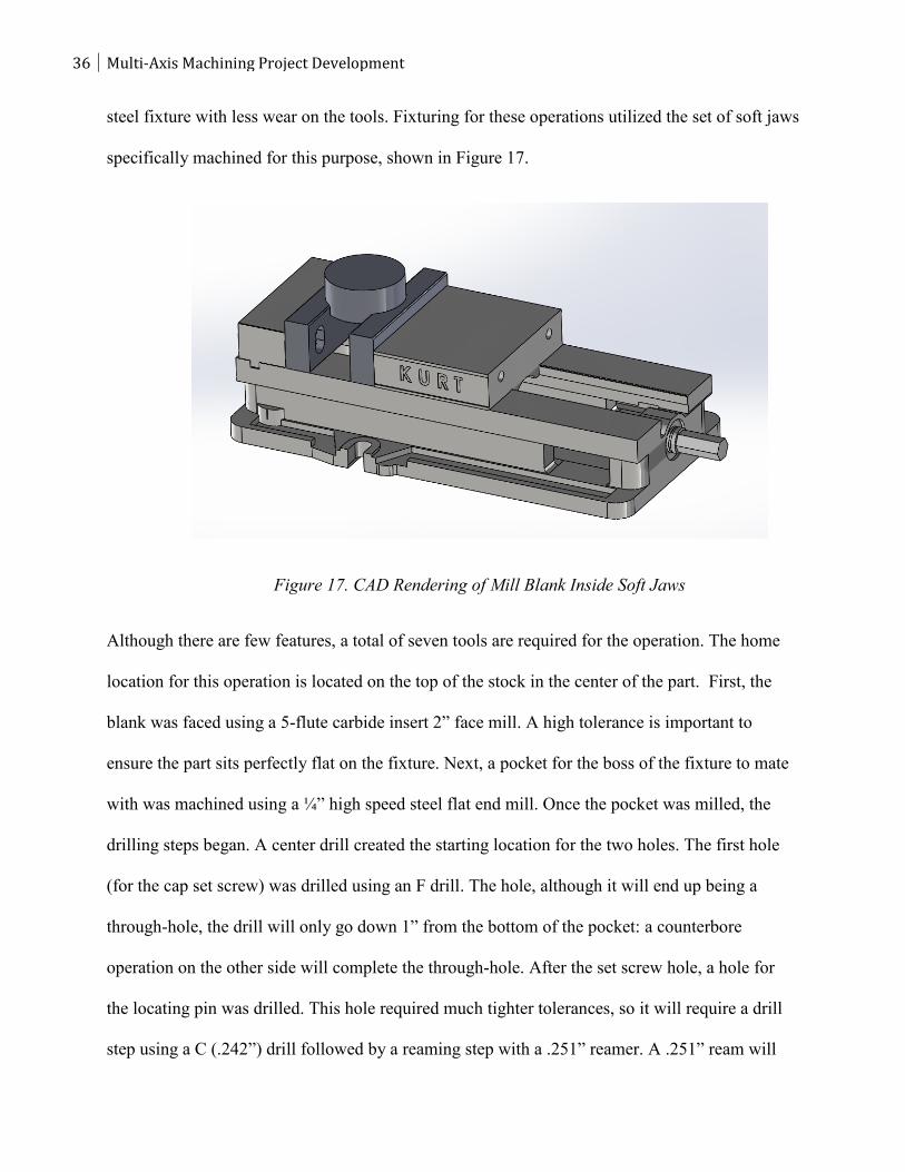
36 Multi-Axis Machining Project Development
steel fixture with less wear on the tools. Fixturing for these operations utilized the set of soft jaws
specifically machined for this purpose, shown in Figure 17.
Figure 17. CAD Rendering of Mill Blank Inside Soft Jaws
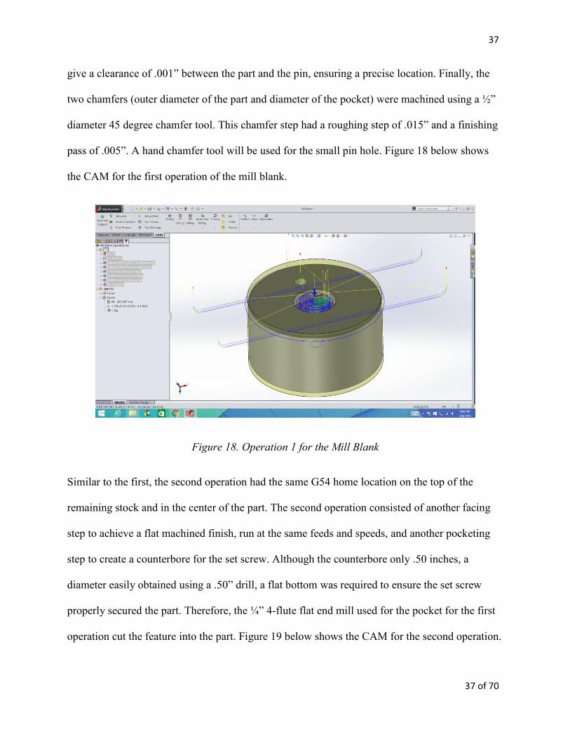
Although there are few features, a total of seven tools are required for the operation. The home
location for this operation is located on the top of the stock in the center of the part. First, the
blank was faced using a 5-flute carbide insert 2” face mill. A high tolerance is important to
ensure the part sits perfectly flat on the fixture. Next, a pocket for the boss of the fixture to mate
with was machined using a ¼” high speed steel flat end mill. Once the pocket was milled, the
drilling steps began. A center drill created the starting location for the two holes. The first hole
(for the cap set screw) was drilled using an F drill. The hole, although it will end up being a
through-hole, the drill will only go down 1” from the bottom of the pocket: a counterbore
operation on the other side will complete the through-hole. After the set screw hole, a hole for
the locating pin was drilled. This hole required much tighter tolerances, so it will require a drill
step using a C (.242”) drill followed by a reaming step with a .251” reamer. A .251” ream will
37
37 of 70
give a clearance of .001” between the part and the pin, ensuring a precise location. Finally, the
two chamfers (outer diameter of the part and diameter of the pocket) were machined using a ½”
diameter 45 degree chamfer tool. This chamfer step had a roughing step of .015” and a finishing
pass of .005”. A hand chamfer tool will be used for the small pin hole. Figure 18 below shows
the CAM for the first operation of the mill blank.
Figure 18. Operation 1 for the Mill Blank
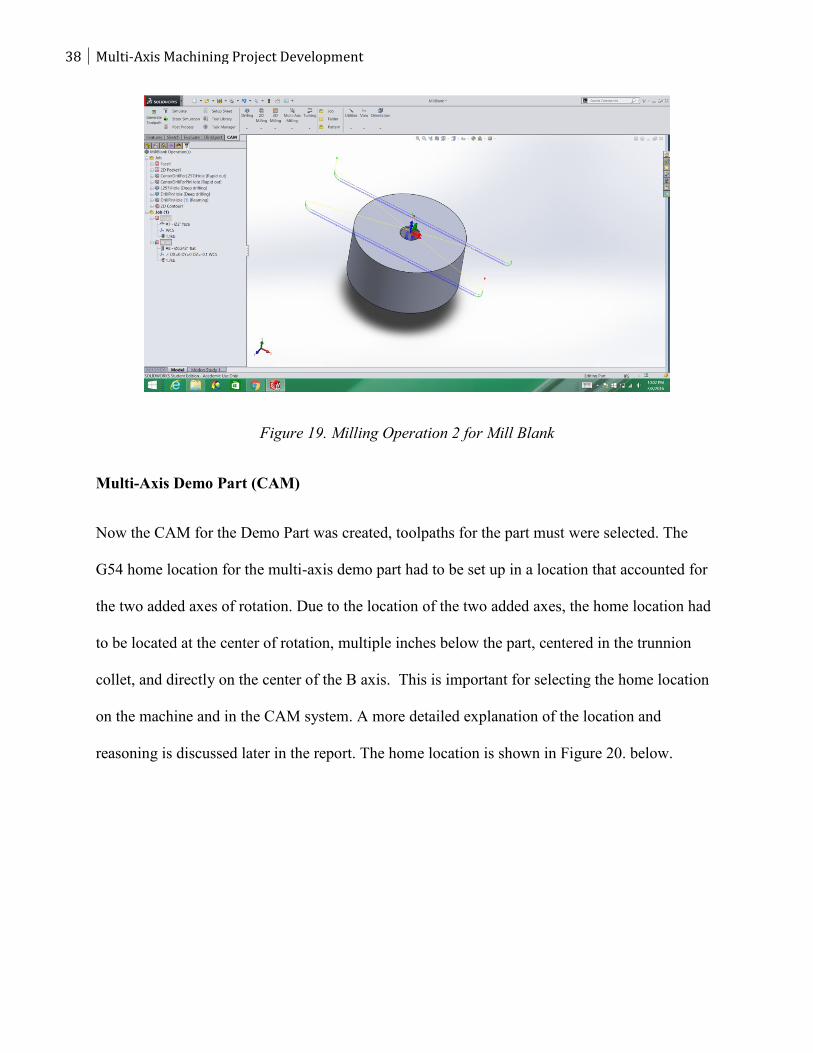
Similar to the first, the second operation had the same G54 home location on the top of the
remaining stock and in the center of the part. The second operation consisted of another facing
step to achieve a flat machined finish, run at the same feeds and speeds, and another pocketing
step to create a counterbore for the set screw. Although the counterbore only .50 inches, a
diameter easily obtained using a .50” drill, a flat bottom was required to ensure the set screw
properly secured the part. Therefore, the ¼” 4-flute flat end mill used for the pocket for the first
operation cut the feature into the part. Figure 19 below shows the CAM for the second operation.
38 Multi-Axis Machining Project Development
Figure 19. Milling Operation 2 for Mill Blank
Multi-Axis Demo Part (CAM)
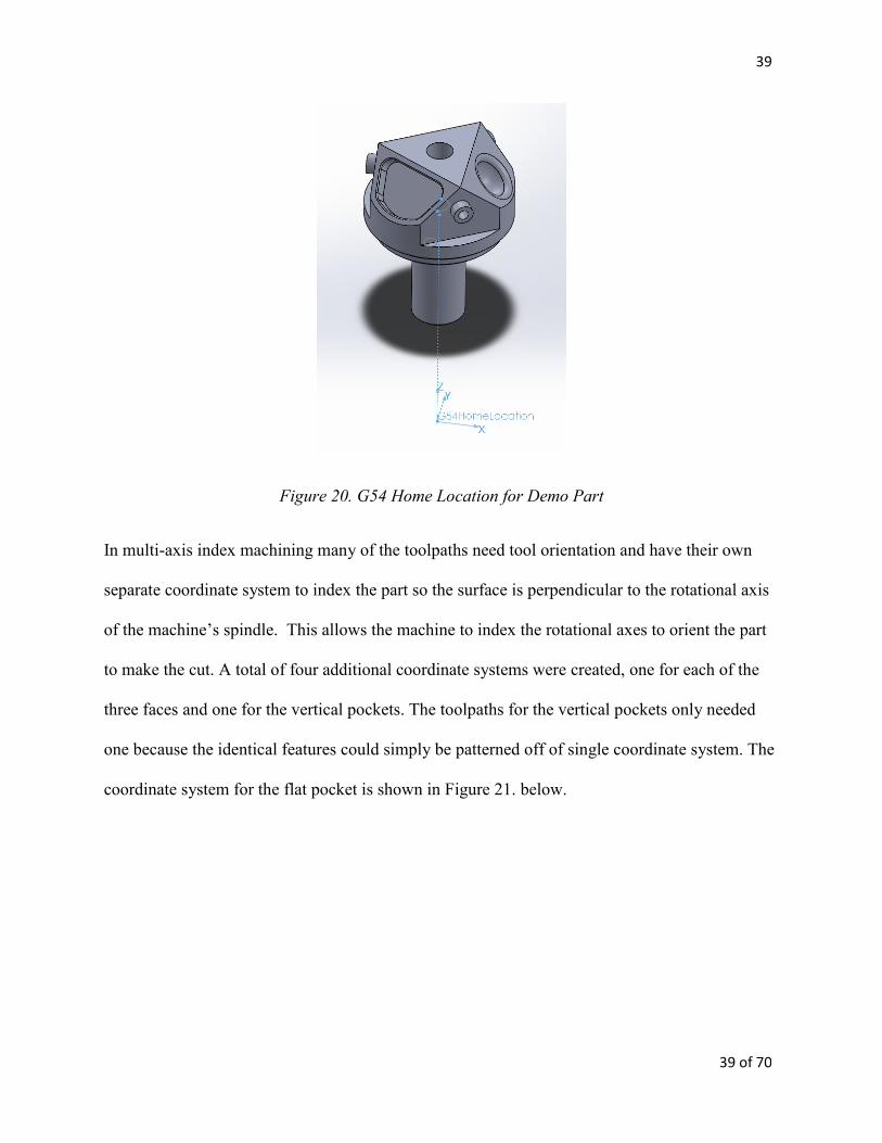
Now the CAM for the Demo Part was created, toolpaths for the part must were selected. The
G54 home location for the multi-axis demo part had to be set up in a location that accounted for
the two added axes of rotation. Due to the location of the two added axes, the home location had
to be located at the center of rotation, multiple inches below the part, centered in the trunnion
collet, and directly on the center of the B axis. This is important for selecting the home location
on the machine and in the CAM system. A more detailed explanation of the location and
reasoning is discussed later in the report. The home location is shown in Figure 20. below.
39
39 of 70
Figure 20. G54 Home Location for Demo Part
In multi-axis index machining many of the toolpaths need tool orientation and have their own
separate coordinate system to index the part so the surface is perpendicular to the rotational axis
of the machine’s spindle. This allows the machine to index the rotational axes to orient the part
to make the cut. A total of four additional coordinate systems were created, one for each of the
three faces and one for the vertical pockets. The toolpaths for the vertical pockets only needed
one because the identical features could simply be patterned off of single coordinate system. The
coordinate system for the flat pocket is shown in Figure 21. below.
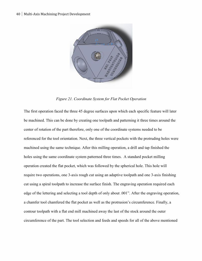
40 Multi-Axis Machining Project Development
Figure 21. Coordinate System for Flat Pocket Operation
The first operation faced the three 45 degree surfaces upon which each specific feature will later
be machined. This can be done by creating one toolpath and patterning it three times around the
center of rotation of the part therefore, only one of the coordinate systems needed to be
referenced for the tool orientation. Next, the three vertical pockets with the protruding holes were
machined using the same technique. After this milling operation, a drill and tap finished the
holes using the same coordinate system patterned three times. A standard pocket milling
operation created the flat pocket, which was followed by the spherical hole. This hole will
require two operations, one 3-axis rough cut using an adaptive toolpath and one 3-axis finishing
cut using a spiral toolpath to increase the surface finish. The engraving operation required each
edge of the lettering and selecting a tool depth of only about .001”. After the engraving operation,
a chamfer tool chamfered the flat pocket as well as the protrusion’s circumference. Finally, a
contour toolpath with a flat end mill machined away the last of the stock around the outer
circumference of the part. The tool selection and feeds and speeds for all of the above mentioned
41
41 of 70
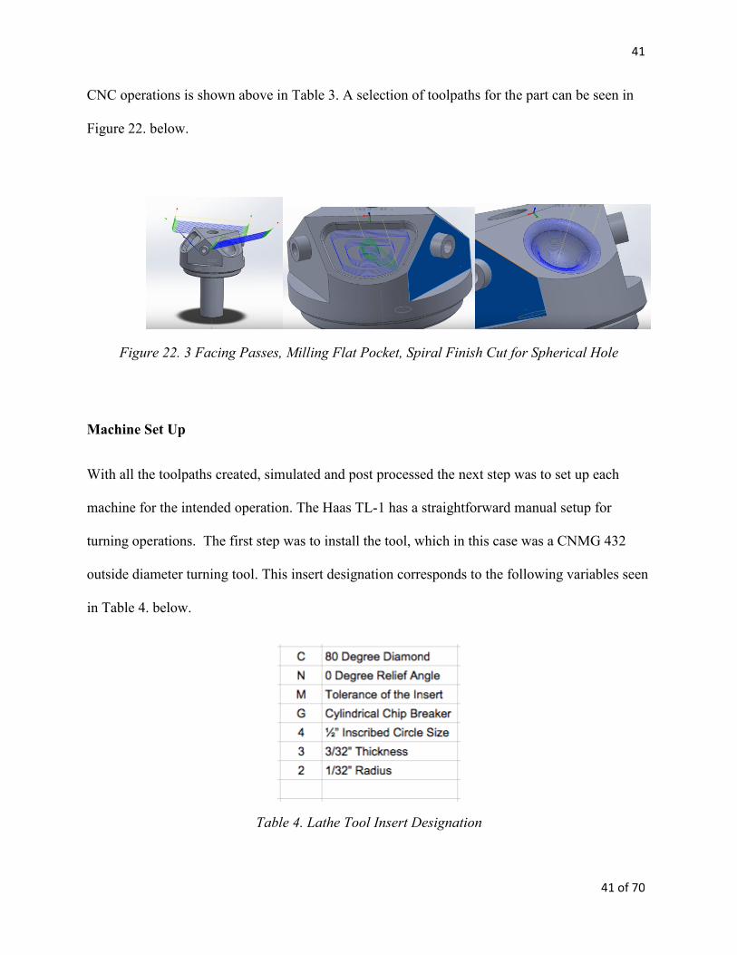
CNC operations is shown above in Table 3. A selection of toolpaths for the part can be seen in
Figure 22. below.
Figure 22. 3 Facing Passes, Milling Flat Pocket, Spiral Finish Cut for Spherical Hole
Machine Set Up
With all the toolpaths created, simulated and post processed the next step was to set up each
machine for the intended operation. The Haas TL-1 has a straightforward manual setup for
turning operations. The first step was to install the tool, which in this case was a CNMG 432
outside diameter turning tool. This insert designation corresponds to the following variables seen
in Table 4. below.
Table 4. Lathe Tool Insert Designation
42 Multi-Axis Machining Project Development
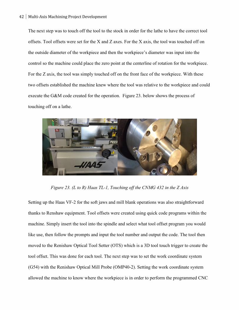
The next step was to touch off the tool to the stock in order for the lathe to have the correct tool
offsets. Tool offsets were set for the X and Z axes. For the X axis, the tool was touched off on
the outside diameter of the workpiece and then the workpiece’s diameter was input into the
control so the machine could place the zero point at the centerline of rotation for the workpiece.
For the Z axis, the tool was simply touched off on the front face of the workpiece. With these
two offsets established the machine knew where the tool was relative to the workpiece and could
execute the G&M code created for the operation. Figure 23. below shows the process of
touching off on a lathe.
Figure 23. (L to R) Haas TL-1, Touching off the CNMG 432 in the Z Axis
Setting up the Haas VF-2 for the soft jaws and mill blank operations was also straightforward
thanks to Renshaw equipment. Tool offsets were created using quick code programs within the
machine. Simply insert the tool into the spindle and select what tool offset program you would
like use, then follow the prompts and input the tool number and output the code. The tool then
moved to the Renishaw Optical Tool Setter (OTS) which is a 3D tool touch trigger to create the
tool offset. This was done for each tool. The next step was to set the work coordinate system
(G54) with the Renishaw Optical Mill Probe (OMP40-2). Setting the work coordinate system
allowed the machine to know where the workpiece is in order to perform the programmed CNC
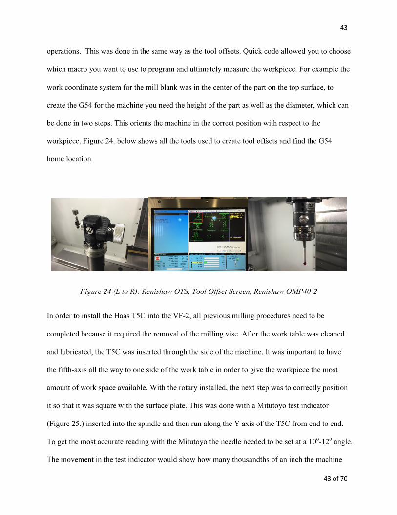
43
43 of 70
operations. This was done in the same way as the tool offsets. Quick code allowed you to choose
which macro you want to use to program and ultimately measure the workpiece. For example the
work coordinate system for the mill blank was in the center of the part on the top surface, to
create the G54 for the machine you need the height of the part as well as the diameter, which can
be done in two steps. This orients the machine in the correct position with respect to the
workpiece. Figure 24. below shows all the tools used to create tool offsets and find the G54
home location.
Figure 24 (L to R): Renishaw OTS, Tool Offset Screen, Renishaw OMP40-2
In order to install the Haas T5C into the VF-2, all previous milling procedures need to be
completed because it required the removal of the milling vise. After the work table was cleaned
and lubricated, the T5C was inserted through the side of the machine. It was important to have
the fifth-axis all the way to one side of the work table in order to give the workpiece the most
amount of work space available. With the rotary installed, the next step was to correctly position
it so that it was square with the surface plate. This was done with a Mitutoyo test indicator
(Figure 25.) inserted into the spindle and then run along the Y axis of the T5C from end to end.
To get the most accurate reading with the Mitutoyo the needle needed to be set at a 10o-12
o angle.
The movement in the test indicator would show how many thousandths of an inch the machine
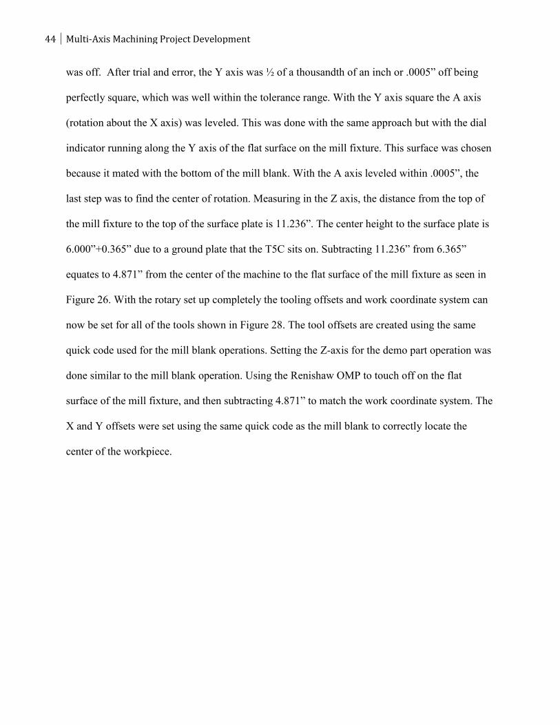
44 Multi-Axis Machining Project Development
was off. After trial and error, the Y axis was ½ of a thousandth of an inch or .0005” off being
perfectly square, which was well within the tolerance range. With the Y axis square the A axis
(rotation about the X axis) was leveled. This was done with the same approach but with the dial
indicator running along the Y axis of the flat surface on the mill fixture. This surface was chosen
because it mated with the bottom of the mill blank. With the A axis leveled within .0005”, the
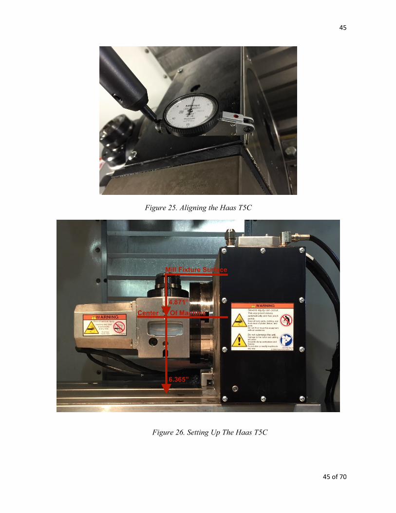
last step was to find the center of rotation. Measuring in the Z axis, the distance from the top of
the mill fixture to the top of the surface plate is 11.236”. The center height to the surface plate is
6.000”+0.365” due to a ground plate that the T5C sits on. Subtracting 11.236” from 6.365”
equates to 4.871” from the center of the machine to the flat surface of the mill fixture as seen in
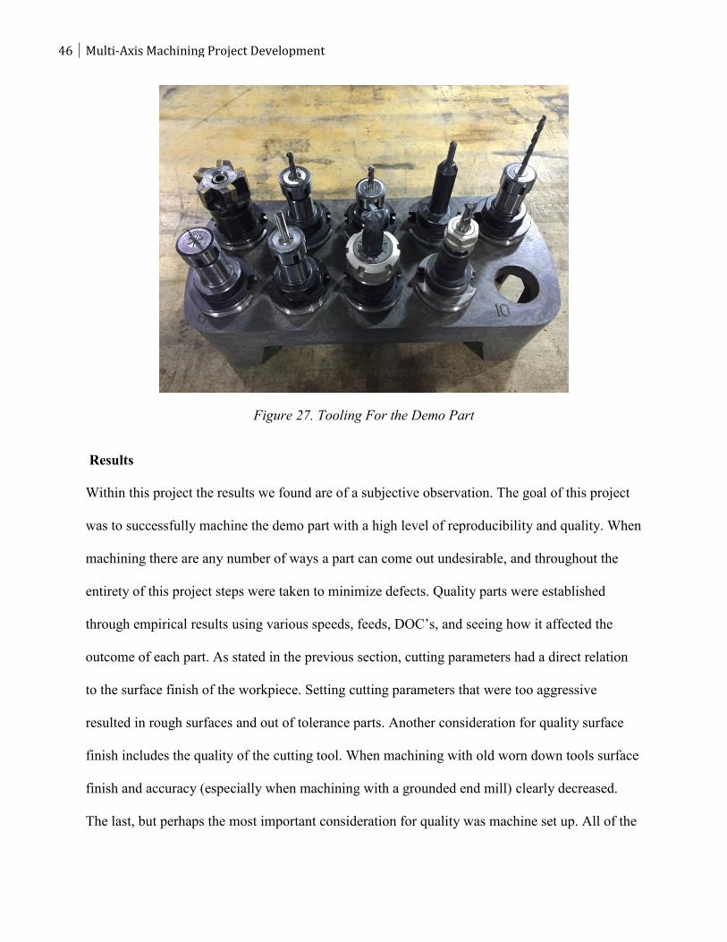
Figure 26. With the rotary set up completely the tooling offsets and work coordinate system can
now be set for all of the tools shown in Figure 28. The tool offsets are created using the same
quick code used for the mill blank operations. Setting the Z-axis for the demo part operation was
done similar to the mill blank operation. Using the Renishaw OMP to touch off on the flat
surface of the mill fixture, and then subtracting 4.871” to match the work coordinate system. The
X and Y offsets were set using the same quick code as the mill blank to correctly locate the
center of the workpiece.
45
45 of 70
Figure 25. Aligning the Haas T5C
Figure 26. Setting Up The Haas T5C
46 Multi-Axis Machining Project Development
Figure 27. Tooling For the Demo Part
Results
Within this project the results we found are of a subjective observation. The goal of this project
was to successfully machine the demo part with a high level of reproducibility and quality. When
machining there are any number of ways a part can come out undesirable, and throughout the
entirety of this project steps were taken to minimize defects. Quality parts were established
through empirical results using various speeds, feeds, DOC’s, and seeing how it affected the
outcome of each part. As stated in the previous section, cutting parameters had a direct relation
to the surface finish of the workpiece. Setting cutting parameters that were too aggressive
resulted in rough surfaces and out of tolerance parts. Another consideration for quality surface
finish includes the quality of the cutting tool. When machining with old worn down tools surface
finish and accuracy (especially when machining with a grounded end mill) clearly decreased.
The last, but perhaps the most important consideration for quality was machine set up. All of the
47
47 of 70
CAD, CAM, and tooling can be setup perfectly, but if the machine is setup incorrectly the
resulting parts will come out undesirable every cycle and out off tolerance.
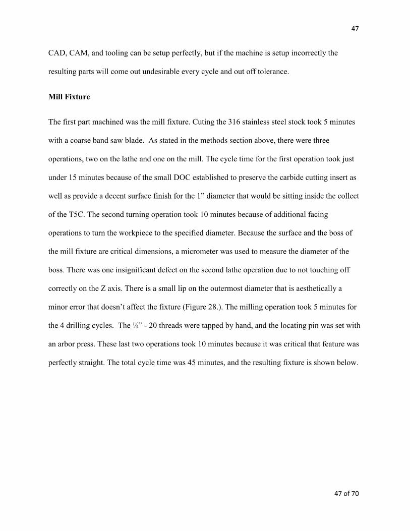
Mill Fixture
The first part machined was the mill fixture. Cuting the 316 stainless steel stock took 5 minutes
with a coarse band saw blade. As stated in the methods section above, there were three
operations, two on the lathe and one on the mill. The cycle time for the first operation took just
under 15 minutes because of the small DOC established to preserve the carbide cutting insert as
well as provide a decent surface finish for the 1” diameter that would be sitting inside the collect
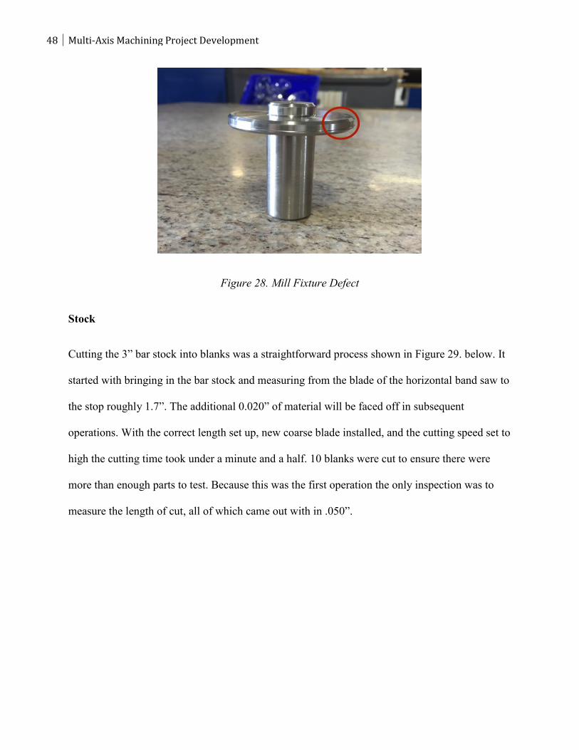
of the T5C. The second turning operation took 10 minutes because of additional facing
operations to turn the workpiece to the specified diameter. Because the surface and the boss of
the mill fixture are critical dimensions, a micrometer was used to measure the diameter of the
boss. There was one insignificant defect on the second lathe operation due to not touching off
correctly on the Z axis. There is a small lip on the outermost diameter that is aesthetically a
minor error that doesn’t affect the fixture (Figure 28.). The milling operation took 5 minutes for
the 4 drilling cycles. The ¼” - 20 threads were tapped by hand, and the locating pin was set with
an arbor press. These last two operations took 10 minutes because it was critical that feature was
perfectly straight. The total cycle time was 45 minutes, and the resulting fixture is shown below.
48 Multi-Axis Machining Project Development
Figure 28. Mill Fixture Defect
Stock
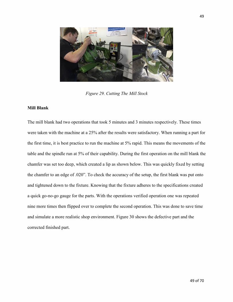
Cutting the 3” bar stock into blanks was a straightforward process shown in Figure 29. below. It
started with bringing in the bar stock and measuring from the blade of the horizontal band saw to
the stop roughly 1.7”. The additional 0.020” of material will be faced off in subsequent
operations. With the correct length set up, new coarse blade installed, and the cutting speed set to
high the cutting time took under a minute and a half. 10 blanks were cut to ensure there were
more than enough parts to test. Because this was the first operation the only inspection was to
measure the length of cut, all of which came out with in .050”.
49
49 of 70
Figure 29. Cutting The Mill Stock
Mill Blank
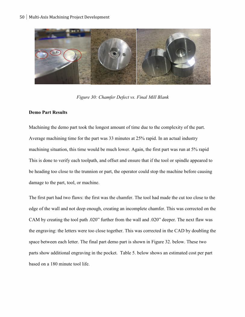
The mill blank had two operations that took 5 minutes and 3 minutes respectively. These times
were taken with the machine at a 25% after the results were satisfactory. When running a part for
the first time, it is best practice to run the machine at 5% rapid. This means the movements of the
table and the spindle run at 5% of their capability. During the first operation on the mill blank the
chamfer was set too deep, which created a lip as shown below. This was quickly fixed by setting
the chamfer to an edge of .020”. To check the accuracy of the setup, the first blank was put onto
and tightened down to the fixture. Knowing that the fixture adheres to the specifications created
a quick go-no-go gauge for the parts. With the operations verified operation one was repeated
nine more times then flipped over to complete the second operation. This was done to save time
and simulate a more realistic shop environment. Figure 30 shows the defective part and the
corrected finished part.
50 Multi-Axis Machining Project Development
Figure 30: Chamfer Defect vs. Final Mill Blank
Demo Part Results
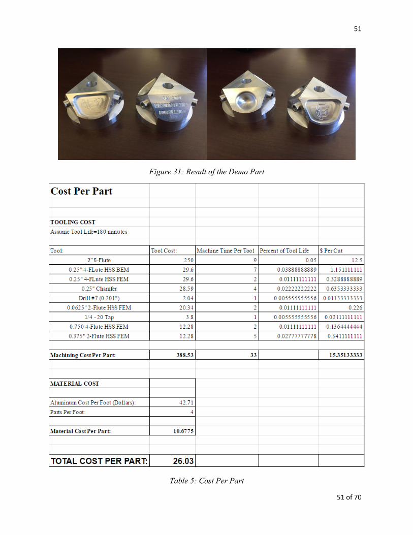
Machining the demo part took the longest amount of time due to the complexity of the part.
Average machining time for the part was 33 minutes at 25% rapid. In an actual industry
machining situation, this time would be much lower. Again, the first part was run at 5% rapid
This is done to verify each toolpath, and offset and ensure that if the tool or spindle appeared to
be heading too close to the trunnion or part, the operator could stop the machine before causing
damage to the part, tool, or machine.
The first part had two flaws: the first was the chamfer. The tool had made the cut too close to the
edge of the wall and not deep enough, creating an incomplete chamfer. This was corrected on the
CAM by creating the tool path .020” further from the wall and .020” deeper. The next flaw was
the engraving: the letters were too close together. This was corrected in the CAD by doubling the
space between each letter. The final part demo part is shown in Figure 32. below. These two
parts show additional engraving in the pocket. Table 5. below shows an estimated cost per part
based on a 180 minute tool life.
51
51 of 70
Figure 31: Result of the Demo Part
Table 5: Cost Per Part
52 Multi-Axis Machining Project Development
Conclusions
The goal of this senior design project was to develop a turnkey project for an advanced CNC
Machining class to be taught in the IME curriculum. The demo part was designed and machined
with the intent of teaching future students about multi-axis positional machining. This project
required previous knowledge of proper design for manufacture techniques as well as advanced
CAD and CAM. The objectives included:
Design a five-axis CNC demo part for IME 336’s five-axis CNC machining project
Create the engineering drawing detailing the parts critical tolerances.
Select all of the tooling required to machine the five-axis demo part.
Design and specify all work-holding required to hold the part.
Develop a CAM program containing all of the necessary tool paths needed to machine
the five-axis CNC demo part to the intended specifications.
Manufacture the demo part to using the existing HAAS CNC hardware in the IME Gene
Haas Advanced Machining Laboratory.
Document and convert the CAM programming, machining setup, and inspection
activities into appropriate lab experiences for the IME 336 class.
The most important results from our project include:
Created an intensive multi-axis machining project for future students
CAD, CAM, and post-processing files for four different parts
Documentation including drawings, routing sheets, and individual job sheets
Machining method produces high quality part consistently
53
53 of 70
In terms of our learning experience as manufacturing engineers, this project took our
understanding of CNC machining to an entirely new level, not to mention the practice using
computer aided-design and manufacturing, creating drawings, and communicating results using
routing and job sheets. From this project, we can see how multi-axis machining is receiving so
much attention in the manufacturing industry due to its increasing the capability of the traditional
3-axis machine. This project has proven to be both challenging and successful, and it is
reassuring that the benefits gained form this project will be passed on to future students.
54 Multi-Axis Machining Project Development
Works Cited
Bolton, Jason, Ashley Miller, and Jennifer Watts. Critical Technology Assessment of Five Axis
Simultaneous Control Machine Tools. Rep. U.S. Department of Commerce Bureau of
Industry and Security Office of Technology Evaluation, July 2009. Web.
Chen, Shang-Liang, and Wen-Tsai Wang. "Computer Aided Manufacturing Technologies for
Centrifugal Compressor Impellers." Journal of Materials Processing Technology 115.3
(2001): 284-93. Web.
Dimitrov, D., and M. Saxer. "Productivity Improvement in Tooling Manufacture through High
Speed 5 Axis Machining." Procedia CIRP 1 (2012): 277-82. Web.
Han, F. Y., D. H. Zhang, M. Luo, and B. H. Wu. "Optimal CNC Plunge Cutter Selection and
Tool Path Generation for Multi-axis Roughing Free-form Surface Impeller Channel." The
International Journal of Advanced Manufacturing Technology Int J Adv Manuf Technol
71.9-12 (2014): 1801-810. Web.
Henriksen, Erik K. (1973). Jig and Fixture Design Manual. New York, N.Y.: Industrial Press
Inc.
HSMWorks. "Latest News." HSMWorks • Integrated CAM for SolidWorks. 2012.
http://www.hsmworks.com/
Lasemi, Ali, Deyi Xue, and Peihua Gu. "Recent Development in CNC Machining of Freeform
Surfaces: A State-of-the-art Review." Computer-Aided Design 42.7 (2010): 641-54. Web.
Logins, Andris, and Toms Torims. "The Influence of High-speed Milling Strategies on 3D
Surface Roughness Parameters." Procedia Engineering 100 (2015): 1253-261. Web.
55
55 of 70
Patel, Kandarp, Gerardo Salas Bolaños, Rajnish Bassi, and Sanjeev Bedi. "Optimal Tool Shape
Selection Based on Surface Geometry for Three-axis CNC Machining." The International
Journal of Advanced Manufacturing Technology Int J Adv Manuf Technol 57.5-8 (2011):
655-70. Web.
Li Qian. "Teaching Multi Axis Complex Surface Machining Via Simulation And
Projects". 2005 Annual Conference, Portland, Oregon, 2005, June. ASEE Conferences,
2005. https://peer.asee.org/15338. Web.
Rao, N., F. Ismail, and S. Bedi. "Tool Path Planning for Five-axis Machining Using the Principal
Axis Method." International Journal of Machine Tools and Manufacture 37.7 (1997):
1025-040. Web.
Zamora, Dave. "Teaching Four and Five-Axis CNC Machining." Innovations in Engineering
Education (2004): 493-97. Web.
56 Multi-Axis Machining Project Development
Appendix A
57
57 of 70
58 Multi-Axis Machining Project Development
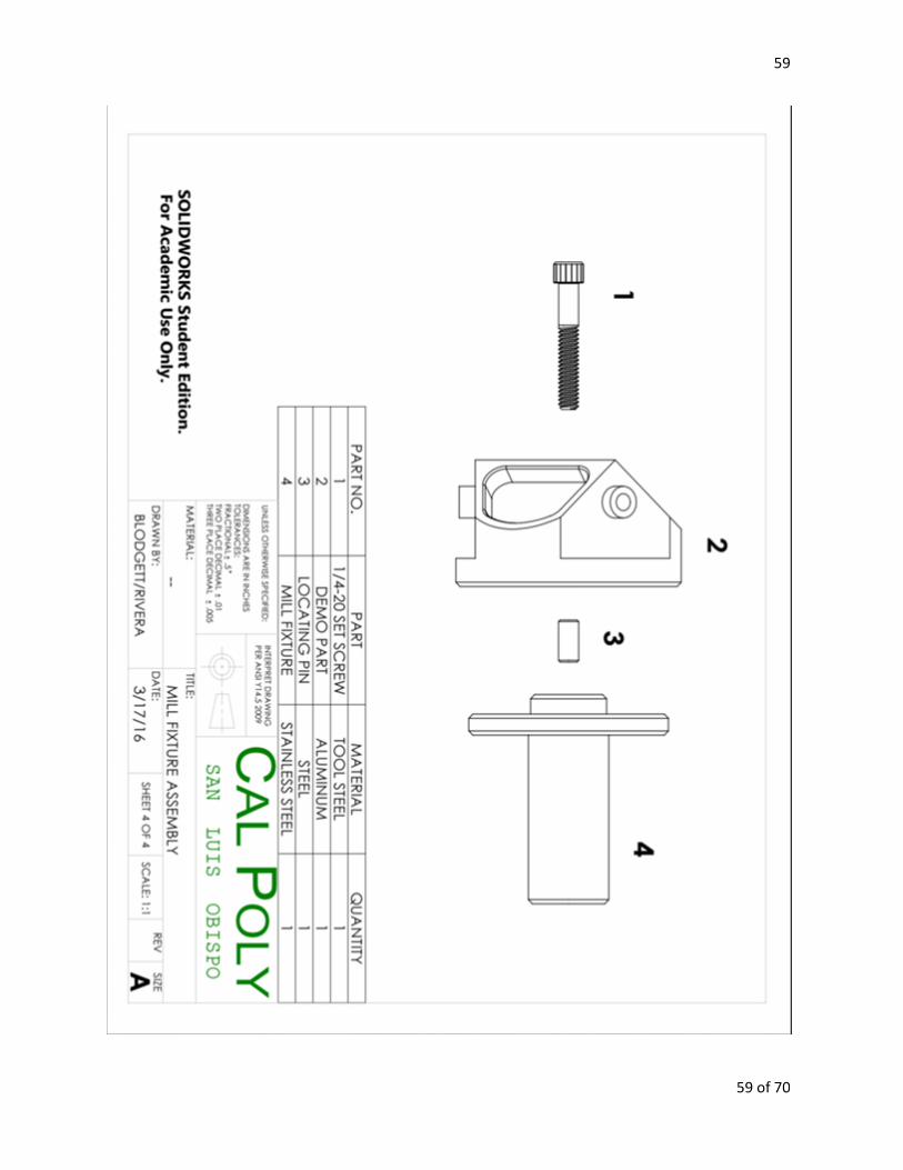
59
59 of 70
60 Multi-Axis Machining Project Development
Appendix B
61
61 of 70
62 Multi-Axis Machining Project Development
63
63 of 70
64 Multi-Axis Machining Project Development
65
65 of 70
66 Multi-Axis Machining Project Development
67
67 of 70
68 Multi-Axis Machining Project Development
69
69 of 70
70 Multi-Axis Machining Project Development