Embed Size (px)
Citation preview

SC COLLABORATOR: A SERVICE ORIENTED FRAMEWORK FOR CONSTRUCTION SUPPLY CHAIN
COLLABORATION AND MONITORING
A DISSERTATION
SUBMITTED TO THE DEPARTMENT OF
CIVIL AND ENVIRONMENTAL ENGINEERING
AND THE COMMITTEE ON GRADUATE STUDIES
OF STANFORD UNIVERSITY
IN PARTIAL FULFILLMENT OF THE REQUIREMENTS
FOR THE DEGREE OF
DOCTOR OF PHILOSOPHY
Chin Pang Cheng
November 2009

ii
© Copyright by Chin Pang Cheng 2009
All Rights Reserved

iii
I certify that I have read this dissertation and that, in my opinion, it is fully adequate in scope and quality as a dissertation for the degree of Doctor of Philosophy.
___________________________________ (Kincho H. Law) Principal Adviser
I certify that I have read this dissertation and that, in my opinion, it is fully adequate in scope and quality as a dissertation for the degree of Doctor of Philosophy.
___________________________________ (Hans C. Bjornsson)
I certify that I have read this dissertation and that, in my opinion, it is fully adequate in scope and quality as a dissertation for the degree of Doctor of Philosophy.
___________________________________ (John Haymaker)
Approved for the University Committee on Graduate Studies.

iv
Abstract
Importance of supply chain integration has been shown in many industry sectors. The
construction industry is one of the least integrated among all major industries. One of the
major reasons is that construction supply chains are unstable and often consist of
numerous distributed members, most of which are small and medium construction
companies. With the proliferation of the Internet and the current maturity of web
services standards, service oriented architecture (SOA) with open source technologies is a
desirable computing model to support construction supply chain integration and
collaboration due to its flexibility and low cost. This thesis investigates and demonstrates
the potential of the current web services technologies and SOA for construction supply
chain collaboration and management, through a prototype service oriented system
framework, namely SC Collaborator (Supply Chain Collaborator).
SC Collaborator is designed and implemented according to the system requirements for
construction supply chain integration. The framework leverages web services and portal
technologies, open standards, and open source packages. Although some web services
systems allow user connection and integration through web services protocol, their
system functions and operations are fixed and not adaptive to changes. The SC
Collaborator framework enables flexible reconfiguration of internal service invocation,
integration, and system layout without recompilation of the system. The framework can
serve as a separate collaborative system, or integrate with other systems such as inventory
management systems.

v
To align a collaborative system with the supply chains it integrates, this thesis proposes
and demonstrates the incorporation of supply chain models in a service oriented system
framework. Specifically, the Supply Chain Operations Reference (SCOR) framework, a
widely used model developed by the Supply Chain Council, is employed to model
construction supply chains. The SCOR modeling framework provides a generic and
hierarchically structured means to specify supply chain networks and processes. The
SCOR process elements and operations are wrapped as individual web service units,
which are integrated and orchestrated in the service oriented SC Collaborator framework.
A case example on a student center construction project is used to illustrate the SCOR
modeling framework for performance monitoring.
The SC Collaborator framework is also extended to support collaboration among
distributed service oriented collaborative systems. Due to the temporary project-based
relationship among participants in construction projects, project participants that do not
have direct business partnership may hesitate to expose and share sensitive and
proprietary information with each other. The distributed SC Collaborator framework
allows users to specify shared information and data. This thesis discusses how
information consistency is ensured among distributed SC Collaborator systems. The
distributed network of SC Collaborator systems is tested with a case scenario of a
completed expansion project of a three-storey residential building.

vi
Acknowledgments
I would like to express my heartfelt thanks to my advisor and mentor, Professor Kincho
H. Law, for his continuous guidance and support, as well as the many inspiring and
enjoyable discussions we had over the years. It has been my privilege to have the
opportunity to share his passion for research and his insights in life. I am greatly
indebted to him.
I would like to extend my gratitude to the rest of my defense committee. I am grateful to
Professor Hans Bjornsson for his valuable collaboration, comments, and suggestions. I
am also grateful to Professor John Haymaker for his advice and feedbacks. I would like
to thank Professor Gio Wiederhold for chairing my defense. I would also like to thank
Professor Bimal Kumar for traveling from Glasgow, Scotland and serving on my defense
committee. I am grateful to Professor Ozalp Ozer for his advice when he was serving on
my dissertation committee.
I would like to express my sincere thanks to many friends for their encouragement and
support. My special thanks go to Henry Chan, Tony Dong, Cheryl Chi, Stephan Jooste,
Forest Flager, and Victor Gane. I would like to extend my thanks to the members of the
Engineering Informatics Group, particularly Dr. Chuck Han, Dr. Gloria Lau, Dr. Julie
Ekstrom, Dr. Yang Wang and Amy Askin, for helping me in various aspects of my
research. I would like to thank Dr. Albert Jones and Dr. Ram Sriram from the National
Institute of Standards and Technology (NIST) for their discussions and comments. I

vii
would also like to thank Wast-Bygg, AB and DPR Construction, Inc. for their time and
data for the case examples presented in this thesis.
I gratefully acknowledge the financial support provided by the National Science
Foundation, Grant Number CMS-0601167, the Center for Integrated Facility Engineering
(CIFE) at Stanford University, the Enterprise Systems Group at the National Institute of
Standards and Technology (NIST), and Wast-Bygg, AB, Sweden. Any opinions and
findings are those of the author, and do not necessarily reflect the views of NSF, CIFE,
NIST or Wast-Bygg, AB. No approval or endorsement of any commercial product by
NIST, NSF, Stanford University or Wast-Bygg, AB is intended or implied.
Finally, I would like to express my deepest gratitude to my family. This thesis would not
be possible without their unconditional love and encouragements over the years. This
thesis is dedicated to them all.

viii
Table of Contents
Abstract iv
Acknowledgments vi
List of Tables xii
List of Figures xiii
1 Introduction 1
1.1 Problem Statement ............................................................................................1
1.2 System Requirements for Construction Supply Chain Integration ...................3
1.2.1 Ease of Installation and Configuration ....................................................4
1.2.2 Low Cost .................................................................................................5
1.2.3 Ease to be Connected and Integrated .......................................................5
1.2.4 Ability to Integrate External Systems and Information ...........................6
1.2.5 Customizable Access to Information and Applications ..........................7
1.3 Current Practices for Supply Chain Integration ................................................7
1.3.1 Electronic Data Interchange (EDI) Standards .........................................8
1.3.2 Enterprise Resource Planning (ERP) Systems ........................................8
1.3.3 Web-Based Collaboration and Project Management Systems in
Construction ..........................................................................................10
1.4 Service Oriented Architecture and Web Services ...........................................11
1.5 Research Objectives ........................................................................................13
1.6 Thesis Outline .................................................................................................14

ix
2 Service Oriented Portal-Based Framework – SC Collaborator 16
2.1 Introduction .....................................................................................................16
2.2 Service Oriented Portal-based Framework .....................................................18
2.3 System Architecture ........................................................................................20
2.3.1 Communication Layer ...........................................................................24
2.3.2 Portal Interface Layer ............................................................................25
2.3.2.1 System Management ...............................................................25
2.3.2.2 User Management ....................................................................27
2.3.2.3 Layout Management ................................................................28
2.3.3 Business Applications Layer .................................................................29
2.3.4 Database Support ...................................................................................30
2.4 Service Oriented Architecture in SC Collaborator .........................................31
2.4.1 Deployment of Basic Web Service Units ..............................................33
2.4.2 Service Invocation and System Layout in Application Portlet Units ....40
2.4.3 Service Aggregation and Orchestration Using Business Process
Execution Language (BPEL) .................................................................45
2.4.3.1 Overview of BPEL ..................................................................47
2.4.3.2 Service Orchestration Using BPEL .........................................48
2.4.3.3 Development and Deployment of BPEL Processes ................52
2.5 Discussions of the SC Collaborator System ...................................................56
2.6 Scenario Examples ..........................................................................................58
2.6.1 Procurement Interactions .......................................................................59
2.6.2 Project Rescheduling .............................................................................64
2.7 Summary .........................................................................................................71
3 Supply Chain Modeling and Performance Monitoring 74
3.1 Introduction .....................................................................................................74
3.2 Supply Chain Operations Reference (SCOR) Model .....................................78
3.3 Modeling of Construction Supply Chains Using SCOR Framework: A
Case Example ..................................................................................................83
x
3.3.1 Case Example ........................................................................................84
3.3.2 SCOR Level 2 Modeling .......................................................................86
3.3.2.1 Stocked Standard Products ......................................................88
3.3.2.2 Make-to-order Standard / Configurable Products ...................89
3.3.2.3 Custom Products ......................................................................91
3.3.3 SCOR Level 3 and Level 4 Modeling ...................................................92
3.3.3.1 Business Process Modeling Notation (BPMN) Models ..........94
3.3.3.2 BPMN Model for SCOR Level 3 Modeling ...........................96
3.3.3.3 BPMN for SCOR Level 4 Modeling .......................................98
3.4 Supply Chain Performance Monitoring ..........................................................99
3.4.1 Supply Chain Performance Metrics .....................................................102
3.4.2 System Implementation .......................................................................106
3.4.2.1 Conversion of BPMN Models into BPEL Skeleton Files .....109
3.4.2.2 Completing BPEL Process Files ...........................................113
3.4.2.3 Deployment of BPEL Process Files ......................................124
3.5 Scenario Demonstration ................................................................................126
3.6 Summary .......................................................................................................130
4 Distributed SC Collaborator Network 133
4.1 Introduction ...................................................................................................133
4.2 Distributed SC Collaborator Network Architecture ......................................135
4.3 Service Security ............................................................................................137
4.4 Information Consistency ...............................................................................139
4.4.1 Consistency Issues in Distributed System Networks ..........................140
4.4.2 Implementation in SC Collaborator .....................................................145
4.5 Scenario Demonstration on the Distributed SC Collaborator Network ........153
4.5.1 E-Procurement .....................................................................................154
4.5.2 Responding to Material Delivery Delay ..............................................159
4.6 Summary .......................................................................................................166
5 Conclusions and Future Works 168

xi
5.1 Summary of Research ...................................................................................168
5.2 Research Contributions .................................................................................170
5.3 Future Directions...........................................................................................172
5.3.1 Ontology Based Systems .....................................................................173
5.3.2 Extending the Research Scope on Modeling .......................................173
5.3.3 Application Programming Interface for SC Collaborator ...................174
5.3.4 Evaluation of SC Collaborator Using TAM ........................................174
5.3.5 Applications of the GreenSCOR Framework ......................................175
Bibliography 177

xii
List of Tables
Number Page
Table 2.1: Examples of the operations of the web service unit Material Order Service
in SC Collaborator ...........................................................................................34
Table 3.1: SCOR Level 2 process categories .....................................................................81
Table 3.2: SCOR Level 3 process elements for “Source” .................................................81
Table 3.3: SCOR Level 3 process elements for “Make” ...................................................82
Table 3.4: SCOR Level 3 process elements for “Deliver” ................................................82
Table 3.5: Examples of supply chain performance metrics used in the case example ....105
Table 3.6: Conversion table from BPMN elements to BPEL elements ...........................111

xiii
List of Figures
Number Page
Figure 1.1: Commonly used web-based collaborative tools ..............................................10
Figure 2.1: Conceptual framework of service oriented portal-based framework ..............19
Figure 2.2: System architecture of the SC Collaborator system ........................................21
Figure 2.3: Homepage of the SC Collaborator system ......................................................24
Figure 2.4: System administrator selecting different modules in SC Collaborator ...........26
Figure 2.5: System administrator managing the sub-module pages ..................................27
Figure 2.6: The application portlet unit for configuring the user permissions of the
“Directory” portlet unit ....................................................................................29
Figure 2.7: Schematic representation of the major information managed in SC
Collaborator .....................................................................................................31
Figure 2.8: Interactions among different parts on the business applications layer in SC
Collaborator .....................................................................................................32
Figure 2.9: Excerpt of the service implementation class for the Material Order Service ..36
Figure 2.10: Java class for data type “productInfoType” ..................................................37
Figure 2.11: Service descriptor file “services.xml” ...........................................................37
Figure 2.12: Excerpt of the WSDL file for the service unit Material Order Service .........39
Figure 2.13: Invocation of web services by the order management portlet unit in SC
Collaborator .....................................................................................................42
Figure 2.14: Excerpt of the JSP codes for the order management portlet unit ..................43

xiv
Figure 2.15: The SOAP request and response messages of the service operation
“getItemInfoById” ...........................................................................................45
Figure 2.16: Schematic representation of the BPEL activities for the operation
“respondOrderNew” ........................................................................................49
Figure 2.17: Excerpt of the BPEL code for the service operation “respondOrderNew” ...51
Figure 2.18: Eclipse BPEL Visual Designer......................................................................52
Figure 2.19: Deployment of BPEL process service “Material Order Service 2” with
service operation “respondOrderNew” ............................................................54
Figure 2.20: Deployment descriptor “deploy.xml” for the BPEL process service with
operation “respondOrderNew” ........................................................................54
Figure 2.21: WSDL document for the process service with operation
“respondOrderNew” ........................................................................................55
Figure 2.22: Workflow in the e-Procurement scenario ......................................................60
Figure 2.23: Integrating online purchasing with CAD and procurement services: (1)
designers dragging items from supplier’s online catalogs to CAD
drawings, (2) extracting the embedded item information to a spreadsheet
in Microsoft Excel, (3) and sending the suggested item list to SC
Collaborator for contractor to review ..............................................................60
Figure 2.24: Contractor’s layout for review of procurement item list and submission
of electronic purchase orders ...........................................................................61
Figure 2.25: Supplier’s layout for managing received purchase orders ............................62
Figure 2.26: Connection to internal and external information and applications in the
portlet unit that suppliers manage and evaluate received purchase orders ......63
Figure 2.27: Contractor’s layout showing updated item status and purchase order
information .......................................................................................................63
Figure 2.28: Floor plan and finished layout of the supermarket in Boras, Sweden ...........64
Figure 2.29: An excerpt of the project schedule between May 2007 and August 2007 ....66
Figure 2.30: Information flows and interactions in the rescheduling process ...................67
Figure 2.31: Supplier’s layout for production reporting ....................................................67

xv
Figure 2.32: Subcontractor’s layout for monitoring material production and delivery .....68
Figure 2.33: Subcontractor’s layout for activity review and adjustment ...........................68
Figure 2.34: Inventory (in m2) of form material (wood) under different supply delay
conditions .........................................................................................................70
Figure 2.35: BPEL process for the operation “changeDeliveryEstimate” .........................72
Figure 3.1: The Supply Chain Model framework [51] introduced by the Global
Supply Chain Forum (GSCF) ..........................................................................76
Figure 3.2: SCOR Level 1 modeling [91] ..........................................................................79
Figure 3.3: Four levels of SCOR business processes [91] .................................................80
Figure 3.4: Inputs and outputs for Level 3 process “S1.1 Schedule Product
Deliveries” .......................................................................................................80
Figure 3.5: 3D model of the two-storey high school student center ..................................84
Figure 3.6: Project schedule showing only the tasks on the critical path ..........................85
Figure 3.7: Flow chart of a typical material planning, procurement, and delivery
management process in construction projects ..................................................87
Figure 3.8: SCOR Level 2 model for a typical construction supply chain for stocked
standard products .............................................................................................89
Figure 3.9: SCOR Level 2 model for a typical construction supply chain for make-to-
order standard / configurable products ............................................................91
Figure 3.10: SCOR Level 2 model for a general construction supply chain for custom
products ............................................................................................................92
Figure 3.11: SCOR Level 3 model for a typical construction supply chain for stocked
standard products .............................................................................................93
Figure 3.12: Snapshot of Eclipse BPMN Modeler ............................................................95
Figure 3.13: Core components in BPMN standard ............................................................96
Figure 3.14: BPMN representation of the SCOR Level 3 model for stocked standard
products ............................................................................................................97
Figure 3.15: BPMN representation of the SCOR Level 3 model for make-to-order
standard / configurable products ......................................................................97

xvi
Figure 3.16: BPMN representation of the SCOR Level 3 model for custom products .....98
Figure 3.17: BPMN graphical representation of the process “Manu D2.2 Receive,
Configure, Enter & Validate Order” in Figure 3.15 ........................................99
Figure 3.18: Development framework for service oriented supply chain performance
monitoring systems using the SCOR framework, open standards, and open
source technologies ........................................................................................101
Figure 3.19: Performance metrics hierarchically structured in the SCOR guidelines .....103
Figure 3.20: Level 4 BPMN model for the process “Manu D2.2 Receive, Configure,
Enter & Validate Order” with addition of two tasks to calculate the cycle
time ................................................................................................................104
Figure 3.21: Incorporating SCOR Level 3 and Level 4 models in SC Collaborator .......107
Figure 3.22: Procedures to incorporate the SCOR models to the service oriented SC
Collaborator system framework .....................................................................108
Figure 3.23: XMI representation of the SCOR Level 4 BPMN model for the process
“Manu D2.2 Receive, Configure, Enter & Validate Order,” which is
shown in Figure 3.20......................................................................................110
Figure 3.24: The linked list of “Process” class instances after parsing the SCOR Level
4 model for the process “Manu D2.2 Receive, Configure, Enter & Validate
Order” ............................................................................................................112
Figure 3.25: BPEL skeleton file converted from the linked list of “Process” class
instances depicted in Figure 3.24 ...................................................................112
Figure 3.26: BPEL skeleton file converted from the “Subcontractor” lane in the
SCOR Level 3 BPMN model for stocked standard products, which is
shown in Figure 3.14......................................................................................113
Figure 3.27: Eclipse BPEL Visual Designer for completing the BPEL process file .......115
Figure 3.28: Creating and assigning partner link to an invoke activity “Check
inventory” ......................................................................................................116
Figure 3.29: Specification details for the “Check inventory” activity added to the
BPEL process file ..........................................................................................117

xvii
Figure 3.30: Displaying the definition of the partner link “Inventory” ...........................118
Figure 3.31: Displaying the specification of the BPEL activity “Check inventory” .......118
Figure 3.32: Excerpt of the complete BPEL process file of the Level 4 model for the
process “Manu D2.2 Receive, Configure, Enter & Validate Order” .............120
Figure 3.33: WSDL file of the Level 4 model for the process “Manu D2.2 Receive,
Configure, Enter & Validate Order” ..............................................................121
Figure 3.34: Excerpt of the complete BPEL process file of the “Subcontractor” role in
the Level 3 model for stocked standard products ..........................................122
Figure 3.35: WSDL file of the “Subcontractor” role in the Level 3 model for stocked
standard products ...........................................................................................123
Figure 3.36: Deployment descriptor of the “Subcontractor” role in the Level 3 model
for stocked standard products ........................................................................125
Figure 3.37: Deployment descriptor of the Level 4 model for the process “Manu D2.2
Receive, Configure, Enter & Validate Order” ...............................................126
Figure 3.38: General contractor registering the distributors and manufacturers .............127
Figure 3.39: SCOR status checking in SC Collaborator ..................................................128
Figure 3.40: Supply chain performance monitoring in SC Collaborator .........................129
Figure 4.1: Centralized SC Collaborator system versus distributed SC Collaborator
network ..........................................................................................................136
Figure 4.2: System architecture for communications among individual SC
Collaborator systems ......................................................................................136
Figure 4.3: Password protected web page allowing users with successful
authentication to view available web service units ........................................138
Figure 4.4: Java implementation class of the service unit Work Schedule Service ........141
Figure 4.5: Business service that changes project schedule and updates individual
distributed work schedules .............................................................................142
Figure 4.6: Pseudo code of the schedule changing business service ...............................143
Figure 4.7: The BPEL process that changes a project schedule ......................................144
Figure 4.8: Java implementation class of the service unit PIP Service ...........................146

xviii
Figure 4.9: Maintaining information consistency in a distributed SC Collaborator
network ..........................................................................................................147
Figure 4.10: Java implementation class of the modified Work Schedule Service ...........149
Figure 4.11: Java class for data type “notificationType” .................................................150
Figure 4.12: BPEL codes showing activity “Change work schedule 2” in a scope .........150
Figure 4.13: Interactions in distributed SC Collaborator network when the BPEL
process that changes a project schedule completes successfully ...................151
Figure 4.14: Interactions in distributed SC Collaborator network when the activity
“Change work schedule 2” fails .....................................................................152
Figure 4.15: 3D model of the three-storey residential building .......................................153
Figure 4.16: Organizations involved in the example scenario .........................................154
Figure 4.17: Original product information of the selected window .................................155
Figure 4.18: Inquiry to window supplier partners ...........................................................157
Figure 4.19: Updated product information of the selected window ................................157
Figure 4.20: E-Procurement by contractor using its SC Collaborator system .................158
Figure 4.21: Supplier managing and responding received purchase orders using its SC
Collabroator system .......................................................................................159
Figure 4.22: Flowchart for coordinating material delivery delay by supplier Anderson.160
Figure 4.23: Originial project schedule ...........................................................................161
Figure 4.24: Application portlet unit in general contractor’s layout that displays
alternative project schedules ..........................................................................163
Figure 4.25: BPEL process that changes the project schedule and the distributed work
schedules in the scenario demonstration ........................................................164
Figure 4.26: SOAP response message showing the connection fault when invoking
the Work Schedule Service unit located in Kent’s system ............................165
Figure 5.1: Technology acceptance model (TAM) [30] ..................................................175
Figure 5.2: The GreenSCOR framework [91] .................................................................176

Chapter 1
Introduction
1.1 Problem Statement
A supply chain consists of a network of key business processes and facilities, involving
end users and suppliers that provide products, services, and information [53].
Traditionally, marketing, distribution, planning, manufacturing, and purchasing units and
organizations along a supply chain often operate independently. The value of integrating
members along supply chains has been studied and identified in many industries [68, 87].
Supply chain integration helps reduce cost, improve responsiveness to changes, increase
service level, and facilitate decision making. In an integrated supply chain, information
is shared and becomes available among the members. This enhances supply chain
visibility and avoids information delays and distortions. Insufficient supply chain
visibility makes members vulnerable to quality and service level problems from business
partners and therefore subject to risks [23, 67]. Information delays and distortions lead to
an increase in demand signal variation along the supply chain upstream, a phenomenon
called the bullwhip effect [57]. Therefore, information sharing is one of the keys to
effective supply chain management.

CHAPTER 1. INTRODUCTION 2
Construction is one of the largest industries in any country of the world [41]. In the
United States, the value of construction put in place was $1,072 billion in 2008 [97], or
7.5% of the U.S. gross domestic product (GDP) that year [18]. There are many
companies and many trades involved in a construction project and development.
Unfortunately, the construction industry is arguably the least integrated among all the
major industrial sectors [34]. New [71] and Cox [26] have also suggested that supply
chain research in construction should focus on the development of interactive, inter-
organizational relationships, which requires integration.
Briscoe and Dainty [17] have summarized eight key attributes to successful construction
supply chain integration: (1) managing communication, (2) managing information flow,
(3) alignment of supply chain systems, (4) mechanisms for problem resolution, (5)
engineering additional value in projects, (6) ensuring high quality standards, (7) securing
commitment to the client and the project objectives, and (8) establishing long-term
supply chain relations. Therefore, system frameworks that can easily align with other
supply chain systems and facilitate communication and information flows are critical to
integration of construction supply chains. O’Brien [75] also emphasizes the importance
of good communication and information sharing between different parties to construction
contracts. In addition, London et al. [61] indicate that strategic management combined
with assured flows of information is critical to the creation of value across supply chains.
However, the high fragmentation and project-based nature of the industry pose a
significant challenge to cross-enterprise integration of information and applications in
construction supply chains. The characteristics of construction supply chains lead to
various requirements for information and collaborative systems such as low cost and
system adaptability. With the proliferation of the Internet and the current maturity of
web services standards, this thesis aims to propose and demonstrate that integration and
collaboration of construction supply chains can be improved by adopting web services
and portal technologies, open standards, open source packages, and the concept of service
oriented architecture (SOA). This thesis presents a prototype service system framework
CHAPTER 1. INTRODUCTION 3
that is designed for managing and integrating construction supply chains. This
framework supports flexible system reconfiguration and integration of scattered
information and application operations, alignment of supply chain configuration, and
communication of distributed systems.
1.2 System Requirements for Construction Supply Chain Integration
Construction supply chains are characterized by the involvement of many companies
from a wide variety of trades [74]. A construction project involves a diverse group of
participants including contractors, architects, engineers, laborers, and developers [43]. A
project of medium to large scale typically involve hundreds of different companies
supplying materials, components, and a wide range of construction services [27]. The
multi-participant and multi-domain characteristic is partly caused by the high
fragmentation of the industry. According to a study on the construction industry in the
United States [64], the top eight architectural, engineering and construction (AEC)
companies control less than twenty percent of the market share while by contrast the top
companies in the aerospace industry control over seventy-five percent of all trades within
the industry. This is probably due to the fact that the construction industry is comprised
of countless companies from many different trades, most of which are small to medium
in size. Furthermore, AEC companies tend to use a wide range of hardware platforms
and software applications for their own operations, posing many technical challenges in
integrating the construction supply chains.
The temporary project-based nature of construction projects also hinders integration of
construction supply chains. Even though the processes can be similar for construction
projects of a specific kind, most construction projects create new products or prototypes
and consist of temporary supply chains that organizations need to be reconfigured for

CHAPTER 1. INTRODUCTION 4
each project [99]. Sharing of information and integration of systems require trust and
coordination. Since construction supply chains are highly dynamic and the
organizational structure and the project team change frequently, it is, therefore, unlikely
for project participants to work together long enough on a project to build enough trust
and to share information willingly. A secure and customizable support system may help
establish trust and encourage integration during short-term partnerships. A flexible
system may facilitate adapting to new configurations and changes in supply chains.
Based on the characteristics of construction supply chains, literature review, and
feedbacks from practitioners in the industry, the following sections summarize the
desirable requirements of a collaborative platform to enhance communication among
members and integration of services in a construction supply chain.
1.2.1 Ease of Installation and Configuration
As discussed in [95], an information infrastructure to interface the members of a supply
chain should simultaneously satisfy three requirements: (1) accommodating members
with varying degrees of IT sophistication, (2) offering a wide range of functionalities, and
(3) allowing constantly changing pool of suppliers and customers. The third requirement
is particularly important for construction supply chains because additions, removals, and
changes of project participants such as the second tier suppliers are common in
construction projects. Furthermore, construction companies often need to extensively
customize each individual business application before usage, because every construction
project is characterized by a unique set of site conditions, project team, and relationships
between project stakeholders [24]. As a result, information systems for construction
supply chain integration should be flexible to allow quick installation and configuration
at the beginning of a project, and to enable easy re-configuration and adaption for
changes throughout the project.
CHAPTER 1. INTRODUCTION 5
1.2.2 Low Cost
Small and medium enterprises (SMEs) play a critical role as subcontractors and suppliers
in construction supply chains. According to a study in the United Kingdom, about 83
percent of the contracting companies in the private sector employ three or less workers
[27]. Almost 98 percent of all the companies employ 24 or less workers, which are
generally defined as small companies. Medium-sized companies that employ between 25
and 114 workers account for a further 2 percent. These SMEs are usually reluctant to
invest much time, money, and effort in information systems and technologies. To create
a network to support data exchange and communication among information sources and
software applications can be expensive. Large corporations routinely spend up to 50
percent of their information technology budgets on application integration [14]. Most of
the SMEs in the construction industry are not able and/or willing to make such a huge
investment. Solutions that are economical are needed.
1.2.3 Ease to be Connected and Integrated
As noted earlier, ability to accommodate users with varying degrees of IT sophistication
is one of the three requirements for supply chain information infrastructure [95]. The
requirement especially applies to the construction industry because participants on a
construction project are from a wide variety of domains and possess different levels of
experience and educational backgrounds. In addition, according to the technology
acceptance model (TAM) [30], the perceived ease of use of a system affects the early
willingness to try and use the system and the subsequent adoption of the system.
Therefore, systems for managing construction supply chains should provide user-friendly
and easily accessible communication interface. It is also important that the
communication interface allows disparate systems to be connected through machine
understandable protocols. In this way, information and applications residing inside a
CHAPTER 1. INTRODUCTION 6
system can be integrated with other applications and systems in the IT infrastructure of an
organization or company.
1.2.4 Ability to Integrate External Systems and
Information
Supply chains involve many participating companies that are geographically distributed
in locations. They may use different systems and keep their information separately. Not
only is it desirable to expose internal applications and system operations securely to
external systems, but it is also beneficial to allow connection and integration with
external systems and information on a collaborative project. Some companies may be
using ERP or database systems to support various business operations. A supply chain
integration system should be able to access and combine these distributed information
sources and systems.
Functionalities of a system become extensible if it can integrate external systems and
information. Ability to extend the functionalities beyond an individual software system
can facilitate usage. For example, functionality of ERP systems usually is limited and
fixed. Therefore, functionality is an important factor for the selection and successful
implementation of an ERP system [49, 50, 70]. An ERP system successfully
implemented on one project may not be applicable to another project. Different projects
may need different system functionalities depending on factors like the construction
processes, project organizations, scopes of planning and management, hardware and
software that the stakeholders use, and the materials and components involved in the
project. It is difficult and costly to customize functionalities of a pre-packaged
commercial ERP system typically for business applications for construction projects
[105]. Many software packages such as CAD programs allow extension of functionality
via application programming interface (API). Likewise, if collaborative systems for

CHAPTER 1. INTRODUCTION 7
enterprise-wide integration can conveniently extend their functionality, the usability of
the systems will be greatly enhanced.
1.2.5 Customizable Access to Information and
Applications
Security is an issue that many companies concern for collaborative systems. Some
project participants may be reluctant to share information with other participants who do
not have a direct business relationship. For example, although a subcontractor may be
willing to share information with direct trading partners and suppliers, the subcontractor
may not be willing to share information with the suppliers of other subcontractors even
though they are involved in the same project. Moreover, many participants in
construction projects work together on a project-based relationship. It is often difficult
for all the project participants to build enough trust and share information with others. A
system that enables users to control and customize the accessibility of information and
applications can promote information sharing.
1.3 Current Practices for Supply Chain Integration
There are many attempts to develop methodologies, technologies, and tools to integrate
various applications for communication and collaboration among supply chain members.
For example, standards for Electronic Data Interchange (EDI) are developed to facilitate
electronic exchange of business information over networks. Enterprise resource planning
(ERP) systems are adopted for inter- and intra-organizational communication. The
Internet has also been leveraged for communication, collaboration, and project
management. The following sections discuss EDI standards, ERP systems, and the
current web-based communication technologies in the construction industry.

CHAPTER 1. INTRODUCTION 8
1.3.1 Electronic Data Interchange (EDI) Standards
Good communications and information sharing among various parties in construction
projects are critical and can be achieved through information technology integration [17,
27]. The issue of Electronic Data Interchange (EDI) for inter-organizational interactions
has been discussed for over twenty years in both academia and industry [33, 40, 45].
National Institute of Standards and Technology (NIST) defined in 1996 that EDI was the
computer-to-computer interchange of strictly formatted messages that represent
documents other than monetary instruments [47]. The formatted data representing the
documents may be transmitted via telecommunications or physically transported on
electronic storage media.
Some companies in the manufacturing industry establish communication networks using
EDI standards such as ANSI ASC X12 standards [5], RosettaNet standards [84], and
ebXML [94] to connect and exchange data with partners. ANSI ASC X12 is the official
designation of the U.S. national standards body founded in 1979 for the development and
maintenance of EDI standards. RosettaNet is a non-profit consortium aimed at
establishing standard processes for the sharing of business information. ebXML is a
XML-based standard sponsored by Organization for the Advancement of Structured
Information Standards (OASIS) and United Nations Centre for Trade Facilitation and
Electronic Business (UN/CEFACT) for the exchange of electronic business information.
These standards and infrastructures provide a stable means for electronic business
communication. However, the implementation of such communication infrastructures
usually requires high cost and long configuration time, partly due to the lack of
information standardization among trading partners.
1.3.2 Enterprise Resource Planning (ERP) Systems
Recently, major construction companies have adopted enterprise resource planning (ERP)
systems to integrate loosely distributed information and applications within and across

CHAPTER 1. INTRODUCTION 9
companies [24]. An ERP system is typically employed to seamlessly integrate all the
information flowing through the company such as finances, accounting, human resources,
supply chain, and customer information [29]. ERP systems can potentially enhance
transparency across the supply chain by eliminating information distortions and increase
information velocity by reducing information delays [3]. Many corporations have
implemented ERP systems to facilitate their front-end customer relationship and to
support their back-end operations.
ERP systems were not designed and are often not suitable for the construction industry
[105]. There are many research studies and efforts on selection and implementation of
‘generic’ ERP systems in the construction industry [2, 24, 25, 86, 105]. Companies that
use a generic ERP system often need to configure and customize it to support their own
business needs. This configuration and customization process usually takes significant
time, effort, and investment. In addition, most ERP systems on the market are mainly
targeted to large companies with a stable supply chain, while construction supply chains
are unstable project-based in nature. Furthermore, adoption of ERP systems does not
often result in significant improvement in project performance as expected. One study
estimated that 96.4% of ERP implementations failed [82] whereas another study reported
that 70% of ERP implementations did not achieve their estimated benefits [4].
ERP systems have many technical limitations such as implementation complexity,
integration problems, and customization problems [93]. Akkermans et al. [3] conducted
an exploratory study on commercial implementation of ERP systems and concluded four
major limitations of ERP systems that often led to unexpected underperformance of these
tools: (1) inability to share internal data efficiently with supply chain partners across
organizational boundaries, (2) inflexibility to accommodate changes of supply chain
structures, (3) lack of functionality beyond managing transactions, and (4) lack of
modular and open system architecture.

CHAPTER 1. INTRODUCTION 10
Connected view of databases
Message (notification)
Web publishing (e.g. web sites, online catalogs)
Screen sharing
Electronic whiteboards
Instant Messaging
Wiki / Blog / Forum
Document sharing
Video conferencing
Tele‐conferencing
Web‐based project management system
Communication and Info sharing Group activity managementStatic/one‐way Dynamic/interactive
Same time(Synchronous)
Different time(Asynchronous)
Figure 1.1: Commonly used web-based collaborative tools
1.3.3 Web-Based Collaboration and Project Management
Systems in Construction
With rapid development of communication technology, the Internet has become
ubiquitously and instantaneously accessible. The proliferation of the Internet makes it
the most cost effective means of driving supply chain integration and information sharing
[58]. Companies increasingly take advantage of the Internet to create a virtual value
chain where individuals and business partners can communicate and collaborate with
each other.
Nowadays in the construction industry, information technology and the Internet have
been leveraged to support multi-organizational collaborations. Examples include web-
based collaborations for design and learning [20, 73, 88], for document and knowledge
management [62, 107], and for project monitoring and management [19, 22, 72]. Figure
1.1 categorizes various means that are currently used for web-based communication and

CHAPTER 1. INTRODUCTION 11
collaboration in the construction industry. In particular, web-based project management
systems (WPMS) and construction project extranets (CPE) have been increasingly used
to support communication in construction projects [11, 72]. CPE is a private network
that is designed for the use of construction projects and hosted by Application Service
Providers (ASP). Project participants can access a CPE through web browsers. System
functionalities of CPEs, usually project specific, can include team communication,
process and project management, organization directory, and document management.
However, the use of these tools is slow in the construction industry because of barriers
such as security issues, a lack of management commitment, high cost, and deployment
inflexibility [63]. In addition, these tools are mostly standalone, specific applications that
cannot be integrated nor extended easily.
1.4 Service Oriented Architecture and Web Services
An Internet-enabled system based on the service oriented architecture (SOA) can address
many of the limitations of ERP systems and CPEs for supply chain integration. SOA is a
model in which information sources and software functionalities are delivered as
individual distinct service units, which are distributed over a network and combined to
create business applications to solve complex problems. SOA enables the dynamic
reconfiguration of supply chains, making them readily adaptable to changing business
models, growing globalization and increasing coordination. Using the SOA approach,
information sources and systems are converted into modular service components that can
be discovered, located and invoked by other applications through a standard protocol.
The service components can be reused by multiple applications or other services residing
on a network. This “plug-and-play” capability allows agile development and quick
reconfiguration of the system, which are essential for building a flexible system for fast
changing supply chains.

CHAPTER 1. INTRODUCTION 12
The shortcomings of traditional ERP systems that were stated by Akkermans et al. [3]
can be partially resolved using the SOA. First, SOA allows partners to share their
internal data by deploying the data into individual service units that are made available
over the network. Second, the “plug-and-play” ability of SOA allows easy and flexible
reconfiguration to accommodate changes of supply chain structures. Third, service
oriented systems not only allow information transfer across organizational boundaries,
but also enable invocation of various applications via the service components. System
functionalities therefore are not bounded and can be extended to operations such as
analysis and evaluation of alternatives. Fourth, service oriented systems can be divided
into modules for control, management and development, providing both modularity and
scalability. As a result, systems using SOA can provide many of the functionalities by
ERP systems while eliminating many shortcomings of ERP systems. Service oriented
systems can potentially provide higher benefits and cost effectiveness to users than ERP
systems.
Web services are the building blocks of SOA. Utilizing the Internet as the
communication network, the web services technology has emerged as a promising tool to
integrate distributed information sources and software functionalities in a flexible,
scalable, and reusable manner. A “web service” can be described as a specific function
that is distributed on the Internet to provide information or services to users through
standardized application-to-application interactions. Leveraging well established Internet
protocols and commonly used machine readable representations, web services can be
located, invoked, combined, and reused. Web services can create dynamic responses and
are different from conventional websites, which deliver only static information. Web
services are self-contained in that the application using the web services does not need to
depend on anything other than the services themselves. They are also self-describing in
that all the information on how to use the services can be obtained from the services
themselves. Web services are encapsulated, meaning that integrated web services can be
updated or replaced without affecting the functionality or integrity of other independent
services. Interoperability is also achieved by web services as applications written in

CHAPTER 1. INTRODUCTION 13
different languages and operating on different operating systems can be integrated via
standardized web services protocol.
1.5 Research Objectives
Cross-enterprise integration of information and applications in construction supply chains
is hindered by the high fragmentation and project-based nature of the industry. The
current information and collaborative systems cannot fully fulfill the requirements of
supply chain integration and management in the construction industry. The objective of
this thesis is thus to investigate and to demonstrate the potential of the concept of service
oriented architecture (SOA) and the current web services and open source technologies
for construction supply chain collaboration and management. Using a service oriented
approach, a collaborative system can be developed based on supply chain models to
reflect the structure of a supply chain. Leveraging web services technology, a distributed
network of collaborative systems can be supported to promote sharing of private
information and operations. This thesis presents a prototype service oriented
collaborative system framework namely SC Collaborator (Supply Chain Collaborator).
SC Collaborator is designed according to the system requirements for managing and
integrating construction supply chains, which are (1) ease of installation and
configuration, (2) low cost, (3) ease to be connected and integrated, (4) ability to
integrate external systems and information, and (5) customizable access to information
and applications. This thesis also illustrates the modeling of construction supply chains,
which results in supply chain models that can be incorporated in the developed prototype
framework.
The prototype SC Collaborator framework presented in this thesis is designed to manage
the procurement, production, and delivery processes among general contractors,
subcontractors, and suppliers. The framework supports flexible system reconfiguration

CHAPTER 1. INTRODUCTION 14
and service composition, alignment of supply chain configuration, and communication
among peer systems. The framework implements service oriented architecture
leveraging web services and portal technologies, open standards, and open source
packages. Unlike the current web services systems, SC Collaborator allows easy and
flexible reconfiguration of system functions and operations, because internal information,
applications and operations in SC Collaborator are delivered as individual web service
units that can be integrated and reused.
1.6 Thesis Outline
This thesis presents the developed prototype system SC Collaborator framework designed
for managing construction supply chains. Its system extensions to incorporate supply
chain models and to support distributed network architecture are then discussed. This
thesis is organized into the following four chapters.
• Chapter 2 presents the service oriented portal-based SC Collaborator system
framework. Open source technologies are leveraged to support the system
communication, the portal-based user interface, the business applications, and the
data management and storage. Open standards for web services are used to
implement SOA in SC Collaborator. This chapter also justifies the suitability of
SC Collaborator for supply chain integration and collaboration in the construction
industry. A procurement scenario and a project rescheduling scenario are
included to demonstrate the potential of SC Collaborator.
• Chapter 3 demonstrates the modeling of construction supply chains and the
leverage of supply chain models for system implementation using a service
oriented approach. The Supply Chain Operations Reference (SCOR) framework
is utilized for supply chain modeling. This chapter describes the SCOR
framework and its uses to model mechanical, electrical and plumbing (MEP)

CHAPTER 1. INTRODUCTION 15
supply chains, with reference to a study of the MEP process of a student center
construction project. The developed SCOR models are then integrated in SC
Collaborator to build a service oriented model-based platform that monitors
supply chain performance.
• Chapter 4 introduces a distributed SC Collaborator network architecture for
promoting information sharing among organizations in a collaborative
environment that each organization owns and fully controls the information it
shares. This chapter discusses the communication between distributed SC
Collaborator systems and addresses the information consistency issue potentially
hindering a distributed network of systems. This chapter illustrates the approach
of logging and fault handling in SC Collaborator for tackling the consistency
issue. The proposed distributed SC Collaborator network is demonstrated and
tested in this chapter using a case scenario based on a completed residential
building expansion project.
• Chapter 5 summaries the development of the SC Collaborator system framework
for facilitating integration of information and operations among supply chain
members in construction projects. Research contributions and suggestions of
potential future research directions are also provided.

Chapter 2
Service Oriented Portal-Based Framework – SC Collaborator
2.1 Introduction
A supply chain is a network of organizations that procure raw materials, transform them
into intermediate goods and then final products, and deliver the products to customers
through a distribution system [56]. These organizations often operate separately, leading
to myopic operations with reduced efficiency and performance. Cross-firm coordination
of processes is often needed among supply chain members to avoid conflicts, since these
members may have different objectives and constraints. Therefore, business-to-business
integration and collaboration are needed to achieve streamlined material, information,
and financial flows across supply chains [81].
The essence of cross-firm supply chain collaboration is to share information, to jointly
develop strategic plans, and to synchronize operations [16]. Collaborative systems exist
to facilitate communication, information sharing, and alignment of supply chain
operations. Some of them enable users to access, retrieve, and modify information

CHAPTER 2. SERVICE ORIENTED PORTAL-BASED FRAMEWORK 17
residing in those systems through standardized web services protocol. A few of them
also allow invocation of web services to exchange data between external systems and to
combine internal system operations with the functionality provided by external web
services. However, current collaborative systems tend not to be easily reconfigured and
extended. For example, service invocation specifications are often embedded in the
source codes which cannot be easily modified. In addition, built-in system operations
and information schema are fixed and are difficult to modify for changing needs.
SC Collaborator (Supply Chain Collaborator) is a prototype system framework developed
for supporting information sharing and system integration along construction supply
chains. In SC Collaborator, invocation and aggregation of web services can be
performed and modified easily without the need to recompile the system. Internal
information, applications, and system operations are wrapped and deployed as separate
web service units for invocation and integration. Therefore, system functionality and
operations can be reconfigured and extended flexibly. The system framework leverages
web portal technology to provide a customizable user interface, and utilizes open source
technologies to minimize implementation costs which hinder the system usability in
construction companies that are SMEs.
A supply chain is a network of business entities collectively responsible for procurement,
manufacturing, and distribution activities associated with one or more families of
products [44]. The SC Collaborator system thus focuses on the buyer-supplier
interactions among suppliers, subcontractors, and general contractors in the processes of
procurement, manufacturing, and delivery. The framework addresses the five system
requirements for construction supply chain management, which are (1) ease of
installation and configuration, (2) low cost, (3) ease to be connected and integrated, (4)
ability to integrate external systems and information, and (5) customizable access to
information and applications.
This chapter is organized as follows. Section 2.2 discusses the service oriented portal-
based framework that the development of SC Collaborator is based on. Section 2.3

CHAPTER 2. SERVICE ORIENTED PORTAL-BASED FRAMEWORK 18
presents the system architecture and components of the SC Collaborator system
framework. Section 2.4 describes the implementation of SOA in SC Collaborator.
Section 2.5 discusses how the SC Collaborator system addresses the system requirements
for construction supply chain integration. Section 2.6 illustrates the flexibility and
extensibility of SC Collaborator through two example scenarios. The first scenario is an
electronic procurement example while the second one is a rescheduling example based on
data collected from a completed construction project of a supermarket in Sweden. This
chapter is concluded with a summary in Section 2.7.
2.2 Service Oriented Portal-based Framework
A web portal is a web-based system that acts as a gateway to a larger system or a network
of web applications. It is a useful tool to aggregate scattered, distributed information and
services into a single point of access regardless of their location or storage mechanism.
The basic operational units of a portal system are web portlets, which are sub-programs
that encapsulate a single or a number of web applications. Portlets generate only a
fragment of a complete HTML code, and therefore need to be contained in a portal
system in order to become visible and accessible. Through the portal system, multiple
information sources and applications can be accessed, retrieved, and integrated into a
workflow or a supply chain.
Web portals are commonly used to build an intranet for content and document
management within organizations [66]. They serve as a repository of information and
documents for data storage, publication, and retrieval. Due to their security and
customizability, web portals allow users to securely access sensitive personal
information, and enable system administrators to manage a huge amount of information
in a centralized manner. There is also a trend to build portal systems for cross-
organizational collaboration. However, there is little, if any, rigorous research on portal

CHAPTER 2. SERVICE ORIENTED PORTAL-BASED FRAMEWORK 19
design, development, maintenance, and updating for facilitating supply chain
management decisions [98].
SC Collaborator is designed and implemented following a service oriented approach as a
portal-based system. A service oriented portal-based framework is a system development
framework that leverages web portal technology to provide a secure and customizable
user interface and implements SOA to integrate information, applications and services in
a flexible and reusable manner. As illustrated in Figure 2.1, conceptually, there are three
functional components in a service oriented portal-based framework.
• The service deployment component allows information sources, application
functionalities and system operations to be wrapped and deployed into individual
web service units, which can be located and invoked by application portlet units
via standardized protocol.
Application Portlet Unit
Portlet gateway
Application Portlet Unit
Portlet gateway
Application Portlet Unit
Portlet gateway
ServiceUnit
Web services
Service Oriented Portal-Based System
App 3 Wrapper
Web services
Fragments of HTML
Fragments of HTML Fragments
of HTML
Service Deployment of
Applications and Info Sources
App 1 Wrapper
Web services
App 2Wrapper
Web services
Source 1 Wrapper
Web servicesSource 2 Wrapper
Web services
Service - Serviceinteraction
Centralized Management and
User Interface
1
2
3
Figure 2.1: Conceptual framework of service oriented portal-based framework

CHAPTER 2. SERVICE ORIENTED PORTAL-BASED FRAMEWORK 20
• In the service-service interaction component, web service units are connected,
integrated and orchestrated into various workflows to perform different business
tasks. The service invocation and composition can be performed by application
portlet units and by web service units. Web service units can be reused in
different workflows or reused multiple times in the same workflow. As a result,
development of repeated system operations is avoided, and applications and
information sources can be used concurrently. In addition, modification of
system functionalities becomes easy and quick as every business process is
divided into separate atomic reusable web service components.
• The centralized user interface component is provided by a web portal system.
The layouts specified in the application portlet units are combined and displayed
through the portal-based interface. As the system layout is independent of the
service implementation, changes in the location or implementation of a web
service unit do not affect the system interface from a user’s perspective. System
reconfiguration is therefore facilitated.
The system architecture which is designed to support these three system functions is
described in the following section in detail.
2.3 System Architecture
Figure 2.2 shows the system architecture of the SC Collaborator framework. The
framework consists of a database support and four layers of integrated functionalities – a
communication layer, a portal interface layer, a business applications layer, and an
extensible computing layer. The communication layer provides a communication
channel for users to access the system. The portal interface layer serves as a unified and
customizable platform to support interactions between users and the system. The
business applications layer provides an environment that connects to internal and external

CHAPTER 2. SERVICE ORIENTED PORTAL-BASED FRAMEWORK 21
web service units for executing various business processes such as order management and
material delivery monitoring. The extensible computing layer may include databases,
software applications, and web services that the business applications layer can integrate
to support high-level or computationally intensive business functions.
As highlighted in Figure 2.2, SC Collaborator implements the service oriented portal-
based framework shown in Figure 2.1. The service deployment component is represented
by the extensible computing layer and the services repository component on the business
applications layer of SC Collaborator. The service-service interaction component is
implemented by both the service units and the application portlet units residing on the
business applications layer of SC Collaborator. The centralized user interface component
is supported by the communication layer and the portal interface layer of SC
Collaborator.
Web browsers
WSDLApache Struts
Apache Axis2
System Management
Portal Interface(Liferay)
User Management
Layout Management
Communication Layer(Apache Tomcat)
Business Applications Layeretc…
Databases
SC Collaborator (Java)
Applications Web services
Clients
HTTP
WAP
SOAP
Wireless devices
Web services
Owners
Engineers
Contractors
Suppliers
Architects
[Centralized User Interface]
[Service - Service Interaction][Service Deployment]
Order Mgt
Procurement Collaboration
Portlets(Java, JSP, Apache Struts)
Services(Apache Axis2, ODE)Material Orders
Schedules
BPEL WSDL
Materials Monitoring
etc…
Extensible Computing
12
3
Hib
erna
te
DB(MySQL)
Figure 2.2: System architecture of the SC Collaborator system

CHAPTER 2. SERVICE ORIENTED PORTAL-BASED FRAMEWORK 22
This multi-layer, modular architecture permits flexible system installation and
maintenance because each layer can be modified or altered easily and independently. For
example, suppose a user has already installed another communication application server
in the company server. To install SC Collaborator on the same server, the user does not
need to install the bundled communication layer and run both communication servers
simultaneously in the same machine, which may affect the performance of both servers.
The user can extract other components from the SC Collaborator, bundle and install them
with the existing application server in the server machine. This flexibility makes system
maintenance easier.
Open standards and open source technologies are utilized in the system design and
implementation of SC Collaborator. Open standards are standard specifications that are
available to the general public and developed through the collaboration of multiple
organizations. Open source software is computer software that is technology-neutral, that
does not place restriction on other software, that distributes the source codes freely, and
that allows users to modify, integrate, and redistribute the software [79]. The open
standards used in SC Collaborator are:
• Simple Object Access Protocol (SOAP) [102], an XML-based protocol and
encoding format specification released by World Wide Web Consortium (W3C)
for data exchange between web services,
• Web Service Description Language (WSDL) [104], an XML-based specification
released by W3C for describing web services, and
• Business Process Execution Language (BPEL) [80], an XML-based specification
released by Organization for the Advancement of Structured Information
Standards (OASIS) for composition and orchestration of web services.
These open standards support the implementation of service oriented architecture in SC
Collaborator. The details of the structure of these web services standards and their
CHAPTER 2. SERVICE ORIENTED PORTAL-BASED FRAMEWORK 23
relationships will be discussed in Section 2.4. The open source tools leveraged in SC
Collaborator are:
• Apache Axis2 [7], a framework developed by the Apache Software Foundation
that supports deployment of web service units and provides system accessibility
using standardized SOAP and WSDL technologies,
• Apache Orchestration Director Engine (ODE) [9], an execution engine developed
by the Apache Software Foundation that deploys and implements BPEL
processes,
• Apache Struts [8], a framework developed by the Apache Software Foundation
that offers system accessibility using web browsers or wireless devices and
enables control of page flows and management of consistent layouts,
• Apache Tomcat [6], a servlet container developed by the Apache Software
Foundation that executes web applications which are programmed and packaged
using the Java Servlet technologies,
• Hibernate [83], a framework developed by JBoss, Inc. (now part of Red Hat) that
provides flexibility to use different relational databases by mapping object-
oriented Java classes to data in traditional relational databases,
• Liferay Portal [60], a web portal system developed by Liferay, Inc. that offers a
web-based user interface with functionalities such as login authentication, content
management, and blogging, and
• MySQL [90], a relational database management system developed and owned by
MySQL AB (a subsidiary of Sun Microsystems) that provides data storage,
retrieval, and management.

CHAPTER 2. SERVICE ORIENTED PORTAL-BASED FRAMEWORK 24
The following sections discuss the leverage of the open standards and open source tools
in the main components of the SC Collaborator framework in detail.
2.3.1 Communication Layer
A user-friendly and readily accessible communication channel is essential to the usability
of a system. The SC Collaborator system uses open source packages – Apache Tomcat
[6], Apache Struts [8], and Apache Axis2 [7] – to enable the connectivity and access to
the system. Apache Tomcat serves as a container for the communication frameworks,
Apache Struts and Apache Axis2. While some information systems require the client-
side to install particular communication software in order to be connected, the Struts
framework that resides in SC Collaborator allows users to access the system using web
browsers, which are commonly available on every computer. Basic security control of
user login with password is provided by the portal interface layer. Figure 2.3 shows the
guest homepage that allows users to log into the system through web browsers. The
Struts framework also enables remote users to access the system using wireless devices
such as personal digital assistants (PDA) via the Wireless Application Protocol (WAP).
Figure 2.3: Homepage of the SC Collaborator system
CHAPTER 2. SERVICE ORIENTED PORTAL-BASED FRAMEWORK 25
The Axis2 framework residing on the communication layer enables system operations of
the SC Collaborator system to be exposed as standard web services. WSDL documents
are used to describe the deployed web service units for service discovery, description,
and invocation. Users can request information from the system and execute internal
operations by invoking the service units via the standardized web services protocol
SOAP.
2.3.2 Portal Interface Layer
2.3.2.1 System Management
An open source web portal system – Liferay Portal [60] – is leveraged to provide a
flexible and customizable user interface in the system. The portal user interface of the
SC Collaborator system is managed in separate modules. Every module represents a
project, an organization, or a group of similar business functionalities. For example,
Figure 2.4 shows the layout of a system administrative user with accessibility
permissions to seven modules designated for a single project namely “SHS Project.” The
My Community module is unique for users to host personal application portlets. The
company module (shown as “GenCon” in Figure 2.4) is available for all the users
registered with the company. The Guest module does not require authentication and is
intended to display project information to the public, if any. The General Contractor,
Subcontractor, and Supplier modules are accessible to the designated users performing
the role of general contractor, subcontractor, or supplier in the SHS Project. The System
Config module contains applications for managing and configuring the system and is
available to users with system administrator role only.
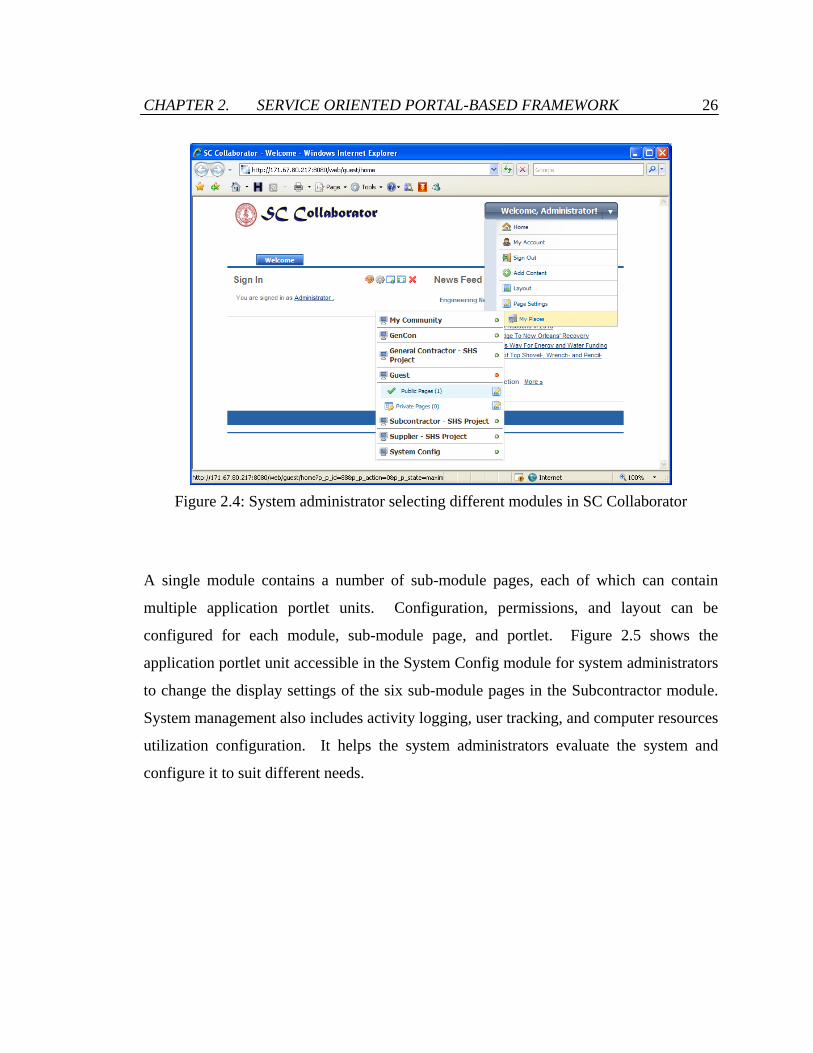
CHAPTER 2. SERVICE ORIENTED PORTAL-BASED FRAMEWORK 26
Figure 2.4: System administrator selecting different modules in SC Collaborator
A single module contains a number of sub-module pages, each of which can contain
multiple application portlet units. Configuration, permissions, and layout can be
configured for each module, sub-module page, and portlet. Figure 2.5 shows the
application portlet unit accessible in the System Config module for system administrators
to change the display settings of the six sub-module pages in the Subcontractor module.
System management also includes activity logging, user tracking, and computer resources
utilization configuration. It helps the system administrators evaluate the system and
configure it to suit different needs.

CHAPTER 2. SERVICE ORIENTED PORTAL-BASED FRAMEWORK 27
Figure 2.5: System administrator managing the sub-module pages
2.3.2.2 User Management
Accessibility of the system functionalities and the internal information and operations can
be assigned to a user at the levels of roles, organizations, user groups, and individual
users. Every user inherits the permissions that are assigned to the role, organization or
user group that the user belongs to. The types of roles in the SC Collaborator system are
system administrator, module administrator, module member, normal user, and guest.
Each role has its predefined set of permissions to the system, layout, modules, sub-
module pages, and portlets. For example, users with system administrative role can view,
configure, and assign permissions of every module, sub-module page, and application
portlet unit. An organization is the company that a user belongs to. A user can be
associated with multiple roles, but only one organization.
Users can be grouped and assigned with a user group name. For instance, SC
Collaborator has three user groups with names “supplier”, “subcontractor” and “general
CHAPTER 2. SERVICE ORIENTED PORTAL-BASED FRAMEWORK 28
contractor.” Suppliers can manage and respond received purchase orders, and share
production and delivery information with customers. Subcontractors and general
contractors can submit and manage purchase orders, monitor product production and
delivery information, and update the information of project tasks. General contractors
can also edit the overall project schedule. Users of different roles, organizations, and/or
user groups can collaborate using the SC Collaborator system.
2.3.2.3 Layout Management
The user interface for web browsers and wireless devices can be configured through the
layout management portlet unit. The portlet unit allows users with either a system
administrator role or a module administrator role to add and delete sub-module pages, to
set up the permissions of sub-module pages, and to configure the sub-module page style.
On each sub-module page, the administrative users can add, delete, and allocate
application portlet units. The administrative users can also grant individual users the
permissions to view and configure a specific module, sub-module page, and portlet.
Therefore, the system layout can be highly customizable so that some modules or portlet
units are available only to the designated users, organizations, or user groups. This
ensures that the right information is delivered to the right person at the right time. Figure
2.6 shows that the system administrator is adding a “view” permission of the “Directory”
portlet unit displayed in the Subcontractor module to the user “Peter Kane.”

CHAPTER 2. SERVICE ORIENTED PORTAL-BASED FRAMEWORK 29
Figure 2.6: The application portlet unit for configuring the user permissions of the
“Directory” portlet unit
2.3.3 Business Applications Layer
The business applications layer implements the service oriented architecture (SOA) in SC
Collaborator. As shown in Figure 2.2, the business applications layer consists of two
components – a repository of web service units and a collection of application portlet
units. The web service units can be simple services performing basic information and
application operations, or composite services supporting complex business processes.
The application portlet units specify the layout of the user interface and invoke both
internal and external web service units.
There are three distinct functional roles of a component in a service oriented computing
model – service providers, service consumers, and service aggregators [13]. Service
providers offer the service implementation, deploy the services, and supply their service
descriptions. Service consumers are the end-users which invoke, locate, and execute the
The user to be assigned with the permission Permission to
view the portlet unit is assigned
Permission to configure the portlet unit is available but not yet assigned to the user
Assigning a permission by moving it from right to left
Name of the applicationportlet unit

CHAPTER 2. SERVICE ORIENTED PORTAL-BASED FRAMEWORK 30
services. Service aggregators consolidate multiple services into a new, single
orchestrated service offering which is commonly known as a business process. A service
aggregator can be considered as a consumer of multiple services and a provider of the
final composite service. The details of service deployment, invocation, and aggregation
on the business applications layer will be presented Section 2.4.
2.3.4 Database Support
In the database tier, an open source relational database – MySQL [90] – is used to store
the application data as well as the system information including user information, layout
configurations, and system settings. The dependencies of the major information managed
in the database are depicted in Figure 2.7. For example, configuration of system layout
and authentication of web service units are dependent on the access rights information,
which is user-specific and organization-specific. Each product item is associated with
information about its buyer and supplier, its purchase order, if any, its product
specification, and the project task that the item is needed. A timestamp is also generated
for all the products at every change in item status (item proposed, purchase order
submitted, purchase order confirmed, item delivered, estimated item arrival, and actual
item arrival). This information is stored in the system to aid evaluate the performance of
business partners and plan the life cycle of each material product. Bottlenecks of the
construction supply chain may also be noticed at an early stage of the project.
The SC Collaborator system is not bounded to a particular database system. The system
can be installed with any Java Database Connectivity (JDBC) [89] compliant database
without any complicated configuration and modification of codes due to the use of the
Hibernate framework. The Hibernate framework maps the objects in a relational
database into object-oriented Java classes. If a user has already installed other databases
such as PostgreSQL and Oracle database, SC Collaborator can integrate with the existing
database with little effort. The user does not need to install and execute MySQL in order
for SC Collaborator to run.

CHAPTER 2. SERVICE ORIENTED PORTAL-BASED FRAMEWORK 31
Figure 2.7: Schematic representation of the major information managed in SC
Collaborator
2.4 Service Oriented Architecture in SC Collaborator
Service oriented architecture (SOA) in SC Collaborator is implemented on the business
applications layer. The layer is comprised of two components – (1) the services
component that takes the roles of service provider and service aggregator, and (2) the
portlets component that takes the role of service consumer. As illustrated in Figure 2.8,
there are three main parts on the business applications layer:
User Interface
Project Schedule
Project Tasks
Organizations
Product Specifications
Purchase Orders
Access Rights
Messages
Service Specifications
Product Timestamps
General Contractor Subcontractors Suppliers
UsersLayout Configuration
Web Browsers
SC Collaborator
Web Browsers

CHAPTER 2. SERVICE ORIENTED PORTAL-BASED FRAMEWORK 32
• Basic web service units, residing on the Apache Axis2 framework, which perform
basic operations such as providing information, running an application, or
manipulating data,
• Application portlet units, residing on the Apache Struts framework, which provide
system layout and allow invocation of web service units, and
• BPEL process service units, residing on the Apache ODE engine, which combine
and orchestrates web service units, which can be basic web service units or BPEL
process service units.
Figure 2.8: Interactions among different parts on the business applications layer in SC
Collaborator
Service implementation classes (Java)
Basic web service units
Deploy
WSDL documents automatically generated
Apache Axis2 Framework
Action controllers
(Java)
App. portlet units (JSP)
Apache Struts Framework
Service descriptor
BPEL process service units
WSDL from
package
Deployment packages
Apache ODE Engine
Deploy
Service spec.
Invoke (SOAP)
Invoke (SOAP)
Invoke (SOAP) Service spec.
Service spec.
Invoke (SOAP)
Invoke (SOAP)
Portlets Component
Services Component

CHAPTER 2. SERVICE ORIENTED PORTAL-BASED FRAMEWORK 33
As illustrated in Figure 2.8, basic web service units are deployed from service
implementation classes written in Java language. Each basic web service unit is
associated with a WSDL document, which is exposed to provide the service consumers
with the information on how to invoke the service unit. A BPEL process service unit is
deployed using a deployment package. The package includes a BPEL process file that
executes service orientation, and a WSDL file that provides service specification
information of the BPEL process service unit. Application portlet units and the
associated action controllers refer to the service specification provided by the WSDL
documents and invoke the basic and BPEL service units via SOAP.
The following sections discusses (1) implementation and deployment of basic web
service units, (2) system layout configuration and service invocation in application portlet
units, and (3) orchestration, development, and deployment of BPEL process service units.
2.4.1 Deployment of Basic Web Service Units
Basic web service units provide fundamental functionalities to support complex
operations. A web service unit can provide one or more operations. For example, the
web service unit Material Order Service in SC Collaborator includes the operation
“getItemDeliveryDetailsById” that obtains the delivery information of a particular
product, the operation “getItemIdByOrder” that provides a list of product items in a
specific purchase order, the operation “changeItemTargetDelivery” that changes the
target delivery date of a product, and the operation “reportItemArrived” that reports the
arrival of a product.
There are two types of web service operations – data service operation and transaction
service operation. Table 2.1 shows some of the data service operations and transaction
service operations of the web service unit Material Order Service as an example.

CHAPTER 2. SERVICE ORIENTED PORTAL-BASED FRAMEWORK 34
Table 2.1: Examples of the operations of the web service unit Material Order Service in
SC Collaborator
Data / Transaction Operation Name Input Parameters Output Parameters
Data getItemIdByOrder orderId itemId getItemIdByTask taskId itemId getItemInfoById itemId buyer, color, itemId,
material, modelNumber, orderId, price, product, productCode, quantity, status, supplier
getItemDelivery-DetailsById
itemId arrival, buyer, deliveryEstimate, deliveryTarget, itemId, orderId, product, productCode, quantity, requested, shipped, supplier
Transaction addItem itemId, productCode, modelNumber, product, buyer, supplier, color, material, quantity, price
notification
changeItem-TargetDelivery
itemId, deliveryTime ---
reportItemArrived itemId --- reportItemOrdered itemId, orderId --- respondOrder orderId,
confirmationNumber, accept, reject
---
• Data service operations provide data to the consumers. This type of operations
may connect to databases and submit queries, run a legacy software application
and obtain the simulation outputs, locate a document and parse it for useful
information, or simply manipulate the input values and offer the results. Data
service operations are request-response in nature and contain both request inputs
and response outputs. For instance, as illustrated in Table 2.1, the data service
operation “getItemDeliveryDetailsById” that provides contractors with the

CHAPTER 2. SERVICE ORIENTED PORTAL-BASED FRAMEWORK 35
delivery details of a purchased product requires both request inputs and response
outputs. For service operations that do not require an input parameter, an empty
request message needs to be sent for service invocation.
• Transaction service operations create, modify, or remove data in an underlying
system. This type of operations may change the data in databases, the values of a
model in software applications, or the content of a document. Transaction service
operations can be request-only or request-response in nature. For example, as
illustrated in Table 2.1, the transaction service operation “reportItemArrived” that
allows contractors to report arrival of product delivery returns no response
message.
Web services can be implemented in programming languages such as Java and C# and be
deployed in various ways using different engines. In SC Collaborator, web services are
implemented in Java and deployed using the open source Apache Axis2 framework
developed by the Apache Software Foundation. A Java service implementation class can
contain multiple functions, each of which will be represented as an individual web
service operation after deployment. As an example, Figure 2.9 shows the Java service
implementation class for a data service operation “getItemInfoById” and a transaction
service operation “respondOrder” of the service unit Material Order Service in SC
Collaborator. As shown in Figure 2.9, the operation “getItemInfoById” receives a
product identification number, submits SQL query to the back-end database, and returns
product specification information in the format of productInfoType, which contains
elements such as product code and status (refer to Figure 2.10). The operation
“respondOrder” receives an order identification number, an order confirmation number,
an array of identification numbers of the product items accepted by the supplier, and an
array of identification numbers of the items rejected by the supplier. The operation then
updates the product information and the purchase order information at the back-end
database and returns nothing.

CHAPTER 2. SERVICE ORIENTED PORTAL-BASED FRAMEWORK 36
import java.sql.*; public class MaterialOrderService { public productInfoType getItemInfoById(String itemId) { productInfoType output = new productInfoType(); try { Class.forName("com.mysql.jdbc.Driver").newInstance(); Connection conn = DriverManager.getConnection
("jdbc:mysql://localhost:3306/portal","",""); Statement stmt = conn.createStatement(); stmt.setQueryTimeout(180); ResultSet rs = stmt.executeQuery("SELECT itemId, productCode,
product, modelNumber, material, color, quantity, price, status, orderId, buyer, supplier FROM materials WHERE itemId='" + itemId + "' ORDER BY productCode");
rs.next(); output.itemId = rs.getString("itemId"); output.productCode = rs.getString("productCode"); ... ... output.orderId = rs.getString("orderId"); conn.close(); } catch (Exception e) { } return output; } ... ... public void respondOrder(String orderId, String confirmationNumber, String[] accept, String[] reject) { try { Class.forName("com.mysql.jdbc.Driver").newInstance(); Connection conn = DriverManager.getConnection
("jdbc:mysql://localhost:3306/portal","",""); Statement stmt = conn.createStatement(); stmt.setQueryTimeout(180); stmt.executeQuery("update purchase_order set replyDate=now(),
confirmationNumber='"+confirmationNumber+"' where orderId='"+orderId+"'");
for (int i = 0; i < accept.length; i++) { stmt.executeUpdate("update materials set status='Confirmed',
confirmed=now() where itemId='"+accept[i]+"'"); } for (int j = 0; j < reject.length; j++) { stmt.executeUpdate("update materials set status='Rejected',
rejected=now() where itemId='"+reject[j]+"'"); } conn.close(); } catch (Exception e) { } } }
Figure 2.9: Excerpt of the service implementation class for the Material Order Service
Name of the web service unit
Name of the web service operation
Input parameters: product ID number
Data type of output
Submission of SQL query
Return product specification information
Service operation “respondOrder” No response returned
Input parameters: order ID, order confirmation number, ID of accepted products, ID of rejected products
Update order information
Update product information

CHAPTER 2. SERVICE ORIENTED PORTAL-BASED FRAMEWORK 37
public class productInfoType { String itemId = ""; String product = ""; String productCode = ""; String modelNumber = ""; String material = ""; String color = ""; int quantity = 0; double price = 0; String buyer = ""; String supplier = ""; String orderId = ""; String status = ""; public String getItemId() { return itemId; } public void setItemId(String itemId) { this.itemId = itemId; } public String getProduct() { return product; } ... ... }
Figure 2.10: Java class for data type “productInfoType”
<service> <parameter name="ServiceClass" locked="false"> MaterialOrderService </parameter> <messageReceivers>
<messageReceiver mep="http://www.w3.org/2004/08/wsdl/in-only" class="org.apache.axis2.rpc.receivers.RPCInOnlyMessageReceiver"/> <messageReceiver mep="http://www.w3.org/2004/08/wsdl/in-out" class="org.apache.axis2.rpc.receivers.RPCMessageReceiver"/>
</messageReceivers> </service>
Figure 2.11: Service descriptor file “services.xml”
The Java service implementation classes are deployed in order to be discovered, located,
and invoked to. To deploy the web service unit Material Order Service using the Axis2
framework, for example, the Java service implementation class and the associated Java
classes are compiled to a single folder. Next, the service descriptor named as
“services.xml” is created to define the class to be used by the service and the appropriate
message receivers, as illustrated in Figure 2.11. The service classes and the service
Parameters of the output data type “productInfoType”
Name of the web service unit Definition class of message receivers for request-only operations
Definition class of message receivers for request-response operations

CHAPTER 2. SERVICE ORIENTED PORTAL-BASED FRAMEWORK 38
descriptor file are then combined and packaged into a file with an extension of “aar.”
Finally, the packaged file is deployed either by using the Axis2 web administration
application or by copying it to the Axis2 services directory.
Once a web service is successfully deployed in the Axis2 framework, a Web Service
Description Language (WSDL)1 [104] file is automatically generated in the framework.
WSDL is a W3C standard for describing web services. WSDL document specifies the
location of a web service on the network, the specific operations available, and the
request and response message formats of a web service. Service consumers can know
how to use a web service by referring to its WSDL document. Figure 2.12 shows an
excerpt of the WSDL of the service unit Material Order Service automatically generated
when the service unit is deployed in the Axis2 framework. There are five major sections
in a WSDL document.
• The Types section specifies the schema definitions of the data types used in the
service.
• The Message section describes an abstract, typed definition of the request and
response messages being exchanged.
• The PortType section provides an abstract set of operations, each of which is an
abstract description of an action supported by the service.
• The Binding section specifies a concrete protocol and data format specification
for a particular port type.
• The Service section is a collection of ports, each of which defines a connection
endpoint as a combination of a binding and a network address.
1 WSDL 1.0 was developed by IBM, Microsoft, and Ariba in 2000. The WSDL 1.1 standard was released
in 2001 while the current version WSDL 2.0 was released in 2007.

CHAPTER 2. SERVICE ORIENTED PORTAL-BASED FRAMEWORK 39
<?xml version="1.0" encoding="UTF-8"?> <wsdl:definitions xmlns:wsdl="http://schemas.xmlsoap.org/wsdl/" xmlns:soap12="http://schemas.xmlsoap.org/wsdl/soap12/" xmlns:xs="http://www.w3.org/2001/XMLSchema" targetNamespace="http://ws.apache.org/axis2"> <wsdl:types> <xs:schema xmlns:ns="http://ws.apache.org/axis2"
targetNamespace="http://ws.apache.org/axis2"> <xs:element name="getItemInfoById"> <xs:complexType> <xs:sequence> <xs:element name="itemId" type="xs:string"/> </xs:sequence> </xs:complexType> </xs:element> <xs:element name="getItemInfoByIdResponse"> <xs:complexType> <xs:sequence> <xs:element name="return" type="ns1:productInfoType"/> </xs:sequence> </xs:complexType> </xs:element> <xs:element name="respondOrder"> <xs:complexType> <xs:sequence> <xs:element name="orderId" type="xs:string"/> <xs:element name="confirmationNumber" type="xs:string"/> <xs:element name="accept" maxOccurs="unbounded" type="xs:string"/> <xs:element name="reject" maxOccurs="unbounded" type="xs:string"/> </xs:sequence> </xs:complexType> </xs:element> ... ... <xs:complexType name="productInfoType"> <xs:sequence> <xs:element name="buyer" type="xs:string"/> ... ... <xs:element name="supplier" type="xs:string"/> </xs:sequence> </xs:complexType> </xs:schema> </wsdl:types> <wsdl:message name="respondOrderRequest"> <wsdl:part name="parameters" element="ns0:respondOrder"/> </wsdl:message> <wsdl:message name="getItemInfoByIdRequest"> <wsdl:part name="parameters" element="ns0:getItemInfoById"/> </wsdl:message> <wsdl:message name="getItemInfoByIdResponse"> <wsdl:part name="parameters" element="ns0:getItemInfoByIdResponse"/> </wsdl:message> ... ... <wsdl:portType name="MaterialOrderServicePortType"> <wsdl:operation name="respondOrder"> <wsdl:input message="ns0:respondOrderRequest" Action="urn:respondOrder"/> </wsdl:operation> <wsdl:operation name="getItemInfoById"> <wsdl:input message="ns0:getItemInfoByIdRequest" Action="urn:getItemInfoById"/> <wsdl:output message="ns0:getItemInfoByIdResponse" Action="urn:getItemInfoByIdResponse"/> </wsdl:operation> ... ... </wsdl:portType> <wsdl:binding name="MaterialOrderServiceSOAP11Binding" type="ns0:MaterialOrderServicePortType"> <wsdl:operation name="respondOrder"> <soap:operation soapAction="urn:respondOrder" style="document"/> <wsdl:input> <soap:body use="literal"/> </wsdl:input> </wsdl:operation> <wsdl:operation name="getItemInfoById"> <soap:operation soapAction="urn:getItemInfoById" style="document"/> <wsdl:input> <soap:body use="literal"/> </wsdl:input> <wsdl:output> <soap:body use="literal"/> </wsdl:output> </wsdl:operation> ... ... </wsdl:binding> <wsdl:service name="MaterialOrderService"> <wsdl:port name="MaterialOrderServiceSOAP11port_http" binding="ns0:MaterialOrderServiceSOAP11Binding"> <soap:address location="http://171.67.80.217:8080/service/processes/MaterialOrderService"/> </wsdl:port> </wsdl:service> </wsdl:definitions>
Figure 2.12: Excerpt of the WSDL file for the service unit Material Order Service
Types
Message
PortType
Binding
Service
1
23
5
4
Target namespace of service
Request message data type name Elements in request message
Elements in response message type data
Name of operation
Location of service
No output response message for “respondOrder”
“getItemInfoById” has both input and output messages
Multiple elements are allowed

CHAPTER 2. SERVICE ORIENTED PORTAL-BASED FRAMEWORK 40
In WSDL, the abstract definition of ports and messages is separated from the network
deployment or data format bindings. This allows the reuse of definitions for messages,
which are abstract descriptions of the data being exchanged, and for port types, which are
abstract collections of operations. For example, from the PortType section of the WSDL
document shown in Figure 2.12, the service operation “respondOrder” is request-only in
nature without response message whereas the operation “getItemInfoById” is request-
response with both request and response messages. As described in the Types and
Message sections, the operation “getItemInfoById” receives one parameter itemId and
returns a result of type productInfoType. The input parameters accept and reject of the
operation “respondOrder” contain an attribute of “maxOccurs” with a value of
“unbounded,” meaning that multiple elements of accept and reject are allowed. These
specifications stay unchanged when the service unit Material Order Service is deployed
in another machine. However, the address of the service location which is specified in
the Service section changes according to the actual service deployment on the network.
2.4.2 Service Invocation and System Layout in
Application Portlet Units
Each application portlet unit in SC Collaborator is an independent unit, which performs a
specific task or business process. The application portlet units are based on Java
framework and JavaServer Pages (JSP) technology. The JSP technology enables HTML
codes to be embedded with Java codes. The HTML codes in a JSP file specify the layout
and display as a regular web page. The embedded Java codes allow various Java-enabled
functionalities such as basic computation, application execution, connection to databases,
and invocation of web services. Therefore, multiple services can be integrated in a single
portlet unit to implement various business processes. For instance, the application portlet
unit that helps retailers to manage the purchase orders they have submitted can integrate
three different services: (1) service that submits purchase orders to manufacturers, (2)
service that monitors the status of each purchase order, and (3) service that triggers

CHAPTER 2. SERVICE ORIENTED PORTAL-BASED FRAMEWORK 41
warning notifications when a problem is encountered. The application portlet units in SC
Collaborator are compliant with Java Specification Request (JSR) 168 standard [1], a
specification that defines a standard programming model for portlet development.
Consequently, the portlet units can be packaged and reused by other portal systems,
allowing high portability across platforms.
There are two ways to invoke a standardized web service. One method to invoke a web
service is by regenerating the implementation classes of the service and importing them
into the programs that service invocation is performed. There exist programs that allow
users to specify the location of a WSDL document and then produce a set of service
implementation Java codes that are consistent with the service specification. Users can
compile the Java codes into client classes and import them as normal external library
classes. Another method is by specifying the location and operation of the service,
initializing the request message, sending the request directly to the deployed service, and
parsing the response message to obtain useful information, in the programs that service
invocation is performed. Unlike the first method, the second method requires
understanding of the schema of the request and response messages and identification of
particular service specifications from a WSDL document, which may pose challenges to
beginner service consumers. However, the second method does not require compilation
of client classes and allows flexible modifications of service invocation. Therefore, the
second method is utilized in the SC Collaborator system.
Take the supplier’s order management portlet unit in SC Collaborator as an example.
The portlet unit allows suppliers to select a particular purchase order they have received,
to view the products that are in the purchase order, and to respond to the order
electronically with a confirmation number. As illustrated in Figure 2.13, the portlet unit
invokes the operation “getIdemIdByOrder” of the Material Order Service to obtain a list
of identification numbers of the products included in the purchase order “PO-WM-389.”

CHAPTER 2. SERVICE ORIENTED PORTAL-BASED FRAMEWORK 42
Figure 2.13: Invocation of web services by the order management portlet unit in SC
Collaborator
After that, the portlet unit invokes the service operation “getItemInfoById” and obtains
the product specification information for each product, which is tabulated in the user
interface display. Figure 2.14 shows an excerpt of the JSP codes of the portlet unit. As
illustrated in Figure 2.14, invocation of a web service operation requires five pieces of
information: (1) target namespace of the service, (2) name of the data type used in the
request message, (3) names of the elements in the request message, (4) location of the
service on the network, and (5) name of the invoked service operation. As labeled in
Figure 2.12 and Figure 2.14, WSDL document of the service operation
“getItemInfoById” being invoked provides all these five pieces of information. System
administrator can refer to the WSDL documents and modify these service invocation
specifications easily to accommodate any change in the service operations being invoked.
Struts framework
“getItemInfoById” service operation
DB
“respondOrder” service
operation
Portlet unit (JSP)
Action controller
(Java)
InformationControl Another JSP page Action
controller (Java) Same page
“getItemIdByOrder” service operation

CHAPTER 2. SERVICE ORIENTED PORTAL-BASED FRAMEWORK 43
... ... <table> <tr> <td colspan=10> List of Materials from Customer "<%= buyer %>" for Order "<%= orderNumber %>" </td> </tr> <tr> <td>Accept</td> <td>Product Code</td> <td>Product</td> <td>Model Number</td> <td>Material</td> <td>Color</td> <td>Quantity</td> <td>Price</td> <td>Total Cost</td> <td>Status</td> </tr> <% // Obtain a list of itemIds OMFactory fac = OMAbstractFactory.getOMFactory(); OMNamespace omNs = fac.createOMNamespace("http://ws.apache.org/axis2", "eig"); OMElement payload = fac.createOMElement("getItemIdByOrder", omNs); OMElement value = fac.createOMElement("orderId", omNs); value.setText(orderNumber); payload.addChild(value); ServiceClient serviceClient = new ServiceClient(); Options options = new Options(); options.setTo(new EndpointReference ("http://171.67.80.217:8080/service/processes/MaterialOrderService")); options.setAction("getItemIdByOrder"); serviceClient.setOptions(options); OMElement result = serviceClient.sendReceive(payload); Iterator<OMElement> iter = result.getChildElements(); while (iter.hasNext()) { String itemId = iter.next().getText(); // For each item, obtain the product specification information OMFactory fac2 = OMAbstractFactory.getOMFactory(); OMNamespace omNs2 = fac2.createOMNamespace("http://ws.apache.org/axis2", "eig"); OMElement payload2 = fac2.createOMElement("getItemInfoById", omNs2); OMElement value2 = fac2.createOMElement("itemId", omNs2); value2.setText(itemId); payload2.addChild(value2); ServiceClient serviceClient2 = new ServiceClient(); Options options2 = new Options(); options2.setTo(new EndpointReference
("http://171.67.80.217:8080/service/processes/MaterialOrderService")); options2.setAction("getItemInfoById"); serviceClient2.setOptions(options2); OMElement result2 = serviceClient2.sendReceive(payload2); Iterator<OMElement> iter2 = result2.getFirstElement().getChildElements(); String buyer2 = iter2.next().getText(); String color = iter2.next().getText(); ... ... String status = iter2.next().getText(); String supplier2 = iter2.next().getText(); %> <tr> <td> <input type=checkbox name="item" value="<%= itemId %>" /> </td> <td><%= productCode %></td> <td><%= product %></td> <td><%= modelNumber %></td> <td><%= material %></td> <td><%= color %></td> <td><%= quantity %></td> <td>$<%= price %></td> <td>$<%= Double.parseDouble(price)*Integer.parseInt(quantity) %></td> <td><%= status %></td> </tr> ... ...
Figure 2.14: Excerpt of the JSP codes for the order management portlet unit
1
23
4
5
Target namespace of service
Request message data type name Elements in
request message
Location of service
Name of operation
Invocation of the service operation “getItemInfoById”
Iterate for every product item, then parse the product ID number
Embedded Java codes in JSP
HTML codes in JSP
Embedded Java codes in JSP
Invocation of the service operation “getIdemIdByOrder”
Internal variable with value “PO-WM-389” in the example
Parse the response message for the product information

CHAPTER 2. SERVICE ORIENTED PORTAL-BASED FRAMEWORK 44
Communication with web service units is performed using Simple Object Access
Protocol (SOAP)2 [102] messaging. SOAP is a W3C standard that provides a protocol
for communications between web services. To invoke a web service operation, the
embedded Java codes in the application portlet units generate a request message in the
SOAP XML format and send it to the service unit through the SOAP. A response
message is returned if the service operation being invoked request-response in nature.
The response message is parsed in the portlet units for information of interest. Figure
2.15 shows the SOAP request and response messages of the service operation
“getItemInfoById.”
In SC Collaborator, invocation of web service units can also be performed by the action
controllers in the Apache Struts framework. The action controllers are intended to
specify the page flow of a portlet unit. Since they are Java-based, they can also be used
to perform business logic, application execution, database connection, and service
invocation. As illustrated in Figure 2.13, the action controllers can be triggered by button
controls in a JSP portlet page. For example, the “PO Overview” button is associated with
an action controller which redirects the portlet unit to another portlet page which shows
all the purchase orders the supplier has received. The “Submit Confirmation” button
triggers an action controller that collects the inputs of the accept checkboxes and the
confirmation number, invokes the service operation “respondOrder,” and redirects to the
same portlet page with updated information.
2 SOAP was originally designed with backing from Microsoft in 1998. SOAP 1.1 became a W3C standard
in 2000. The current version is SOAP 1.2, which was released as a W3C standard in 2003 (first edition) and in 2007 (second edition) respectively.

CHAPTER 2. SERVICE ORIENTED PORTAL-BASED FRAMEWORK 45
<soapenv:Envelope xmlns:soapenv="http://schemas.xmlsoap.org/soap/envelope/" xmlns:q0="http://ws.apache.org/axis2" xmlns:xsd="http://www.w3.org/2001/XMLSchema" xmlns:xsi="http://www.w3.org/2001/XMLSchema-instance">
<soapenv:Body> <q0:getItemInfoById> <q0:itemId>KO-AN-4793</q0:itemId> </q0:getItemInfoById> </soapenv:Body> </soapenv:Envelope>
<soapenv:Envelope
xmlns:soapenv="http://schemas.xmlsoap.org/soap/envelope/"> <soapenv:Body> <getItemInfoByIdResponse xmlns:ns="http://ws.apache.org/axis2"> <ns:return xmlns:ax21="http://ws.apache.org/axis2/xsd"
type="productInfoType"> <ax21:buyer>GenCon</ax21:buyer> <ax21:color /> <ax21:itemId>KO-AN-4793-1</ax21:itemId> <ax21:material>MetalGlass</ax21:material> <ax21:modelNumber>WIN-200-DHL</ax21:modelNumber> <ax21:orderId>PO-WM-389</ax21:orderId> <ax21:price>278.0</ax21:price> <ax21:product>Window</ax21:product> <ax21:productCode>KO-AN-4793</ax21:productCode> <ax21:quantity>63</ax21:quantity> <ax21:status>Sent</ax21:status> <ax21:supplier>Anderson</ax21:supplier>
</ns:return> </getItemInfoByIdResponse> </soapenv:Body> </soapenv:Envelope>
Figure 2.15: The SOAP request and response messages of the service operation
“getItemInfoById”
2.4.3 Service Aggregation and Orchestration Using
Business Process Execution Language (BPEL)
In a service oriented portal framework, information, applications and internal system
operations are deployed and delivered as web services. These basic web services usually
Information being parsed by the embedded Java codes in the order management application portlet unit

CHAPTER 2. SERVICE ORIENTED PORTAL-BASED FRAMEWORK 46
are not sufficient to perform a business process individually. These web services often
need to be aggregated with each other into a workflow. For instance, multiple cross-
application activities are required to implement a business process “add purchase order.”
These activities may include adding a purchase order to the production plan, sending
confirmation to the customer, changing the status of the order and the corresponding
items, and allocating materials and resources to fulfill the order. Each of these activity
components could be separated and deployed as individual web services. A mechanism
to combine and coordinate these activity component services is necessary to complete a
business process.
There are several research efforts on the mechanisms to invoke, terminate, and combine
web-based services. Cheng [21] has developed a simulation access language (SimAL)
and framework that integrate legacy project management applications, manage the
information flow among them, and allow users to build up scenarios for engineering
simulation. Benatallah et al. [12] presents a framework called Self-Serv which consists
of a runtime environment that performs dynamic provider selection and orchestrates
composite services using SOAP standard. Greenwood et al. [35] introduces a framework
namely Web Service Integration Gateway Service (WSIGS) which allows combination of
web services and software agents by message encodings translation and exchange using
WSDL, SOAP and UDDI standards. Maamar et al. [65] attempts to deploy web services
into agents, each of which contains a service chart diagram that defines the underlying
web service and is able to interact with peer agents through XML-based conversation
messages.
Standards are also available to support composition and orchestration of web services.
Web Services Choreography Description Language (WS-CDL) [103] and Web Services
Choreography Interface (WSCI) [100] are W3C standards that provide a global, message-
oriented view of interactions by describing the collective message exchanges among the
interacting web services. Web Services Conservation Language (WSCL) [101] published
by W3C helps specify the XML documents being exchanged among web services and the

CHAPTER 2. SERVICE ORIENTED PORTAL-BASED FRAMEWORK 47
sequence of these document exchanges. However, these standards only provide an
abstract specification of web services composition. Supports for programming and
executing these standards are also very limited. In contrast, Business Process Execution
Language (BPEL)3 is an implementation-level standard for web services composition and
supported by commercial and open source orchestration engines for execution. The
integration and orchestration of the web service units in SC Collaborator using BPEL will
be discussed next.
2.4.3.1 Overview of BPEL
BPEL is an executable XML-based language for specifying a business process in which
most of the tasks represent interactions between the process and external web services.
The language is interpreted and executed by an orchestration engine which realizes the
process flow and invokes the connected web services. BPEL is a layer on top of WSDL
and XML Schema, with WSDL and XML Schema defining the structural aspects of
service interactions, and BPEL defining the behavioral aspects.
The BPEL standard supports two kinds of activity coordination – basic activities and
structured activities. Basic activities, also called primitive activities, correspond to
atomic actions such as message exchange and service initiation that are being performed
within a process. For instance, an invoke activity invokes an operation of some web
service units. A receive activity waits for a message from an external partner. A reply
activity sends response messages to an external partner. A wait activity pauses for a
certain period of time. An assign activity copies data from one place to another. In a
3 BPEL was first developed in 2002 by BEA Systems, IBM, and Microsoft. The BPEL 1.0 standard was a
merger of Web Services Flow Language (WSFL) [59] and XLANG [92], which were developed in 2001 by IBM and Microsoft respectively. In 2003, the three companies together with SAP and Siebel Systems modified BPEL 1.0 into Business Process Execution Language for Web Services (BPEL4WS) 1.1 [10] and submitted the BPEL4WS 1.1 to Organization for the Advancement of Structured Information Standards (OASIS) for standardization. The current version is Web Services Business Process Execution Language (WS-BPEL) 2.0 [80], which was published as one of the OASIS standards by the BPEL Technical Committee of OASIS in 2007.

CHAPTER 2. SERVICE ORIENTED PORTAL-BASED FRAMEWORK 48
BPEL process, partners interact through web service interfaces called port types, and the
structure of the relationship at the interface level is specified by a partner link. Invoke,
receive, and reply activities are three types of interaction activities defined in the BPEL
specification. These interaction activities need to specify the partner link through which
the interaction occurs, the operation involved, the port type in the partner link that is
being used, and the input and output variables that will be read from or written to.
Structured activities manage the overall process flow, specifying what activities should
run and in what order. One can think of structured activities as the underlying
programming logic for a BPEL process. There are eight structured activities in BPEL
2.0: sequence, flow, if, pick, while, repeat-until, scope, and for-each. A sequence activity
contains one or more activities that are performed sequentially. A flow activity allows
parallel execution of activities. A if activity provides conditional routing between
activities. A pick activity executes a conditional branch when it is triggered by either a
message event or an alarm event. While and repeat-until activities repeats performance
of an activity in a structured loop until a certain condition no longer holds true. A scope
activity groups activities into a block, which is treated as an individual unit. A for-each
activity iteratively executes an activity according to an internal counter. Structured
activities can be nested and combined in arbitrary ways, thus enabling the presentation of
complex structures.
2.4.3.2 Service Orchestration Using BPEL
BPEL defines a model and a grammar for describing the behavior of a business process
based on interactions between the process and its partners. A BPEL process consists of a
set of activities that can be combined through structured operators. The interaction
activities – invoke, receive and reply – connects internal or external web service units
while other BEPL activities specify the flow and logic among the interaction activities.
Therefore, BPEL can integrate individual web service units and orchestrate them to offer
specific business functions.

CHAPTER 2. SERVICE ORIENTED PORTAL-BASED FRAMEWORK 49
for-each
receive
flow
invoke
invoke
reply
port
port
port Material Order
partner linkclient
Inventory
partner link
partner link
partner link
Message
if
invoke
port
orderIdconfirm numberacceptreject
notification
respondOrderNew[Material Order Service 2]
confirm number NOT empty
orderIdconfirm numberacceptreject
notification
notification
itemIdincrementElse
respondOrder-New
[Material Order Service 2]
respondOrder[Material Order
Service]
changeInventory[Inventory Service]
addMessage[Message Service]
Figure 2.16: Schematic representation of the BPEL activities for the operation
“respondOrderNew”
As an example, a BPEL process operation “respondOrderNew” is created to extend the
operation “respondOrder” of the service unit Material Order Service using BPEL. Figure
2.16 depicts the behavior of the BPEL process operation “respondOrderNew.” The
activities with solid lines are BPEL basic interaction activities whereas the activities with
dotted lines are structured activities. The service operation “respondOrder” has been
described in Section 2.4.1. Both operations “respondOrderNew” and “respondOrder”
receive an order identification number, an order confirmation number, a list of
identification numbers of the accepted products, and a list of identification numbers of
the rejected products, and then update the information of the corresponding purchase
order and product items.
Other functionalities can be added to the created operation “respondOrderNew.” As
illustrated in Figure 2.16, after receiving the input parameters from the partner link
“client,” the operation “respondOrderNew” checks whether the confirmation number
input is empty. If not, the operation performs two tasks concurrently – (1) updating order
and product information, and (2) updating the inventory planning information. The
former task is done by invoking the operation “respondOrder” of the service unit Material

CHAPTER 2. SERVICE ORIENTED PORTAL-BASED FRAMEWORK 50
Order Service through partner link “Material Order.” The latter task is performed by
invoking the operation “changeInventory” of the service unit Inventory Service through
partner link “Inventory” for each accepted product. The operation “changeInventory” is
request-response in nature. It receives input parameters of a product identification
number and the increment on product inventory record required to change, and returns a
notification to the service consumers. After that, the operation “respondOrderNew”
sends a notification to the supplier record by invoking the operation “addMessage” of the
service unit Message Service through partner link “Message.” Finally, the operation
“respondOrderNew” returns a notification to the customer.
Figure 2.17 shows the BPEL code that defnes an executiable “respondOrderNew”
process. As illustrated in Figure 2.17, there are four sections in a BPEL process file.
• The Import section specifies the WSDL documents of the external service units
invoked by the BPEL process.
• The PartnerLinks section indicates the role of the partner and the process itself.
• The Variables section describes the name and message type of the variables
defined in the process.
• The orchestration logic section defines the flow and implementation details of
each activity in the process.
This example illustrates that functionalities provided by basic web service units can be
combined and orchestrated in BPEL process service units to provide complex business
operations. BPEL process can also invoke and combine other BPEL process service
units. In other words, recursive service composition is allowed and service units of
different level of complexity can be built based on the basic service units.

CHAPTER 2. SERVICE ORIENTED PORTAL-BASED FRAMEWORK 51
<bpel:process name="MaterialOrderService2" suppressJoinFailure="yes" targetNamespace="http://171.67.80.217:8080/service/processes/MaterialOrderService2" xmlns:tns="http://171.67.80.217:8080/service/processes/MaterialOrderService2" xmlns:bpel="http://docs.oasis-open.org/wsbpel/2.0/process/executable" xmlns:ns="http://ws.apache.org/axis2"> <bpel:import namespace="http://ws.apache.org/axis2" location="InventoryService.wsdl" importType="http://schemas.xmlsoap.org/wsdl/" /> <bpel:import namespace="http://ws.apache.org/axis2" location="MaterialOrderService.wsdl" importType="http://schemas.xmlsoap.org/wsdl/" />
<bpel:import namespace="http://ws.apache.org/axis2" location="MessageService.wsdl" importType="http://schemas.xmlsoap.org/wsdl/" />
<bpel:partnerLinks> <bpel:partnerLink name="client" partnerLinkType="tns:MaterialOrderService2" myRole="MaterialOrderService2Provider" /> <bpel:partnerLink name="MaterialOrder" partnerLinkType="tns:MaterialOrderPLT" partnerRole="serviceProvider" /> <bpel:partnerLink name="Inventory" partnerLinkType="tns:InventoryPTL" partnerRole="serviceProvider" /> <bpel:partnerLink name="Message" partnerLinkType="tns:Message" partnerRole="serviceProvider" /> </bpel:partnerLinks> <bpel:variables> <bpel:variable name="input" messageType="tns:MaterialOrderService2RequestMessage"/> <bpel:variable name="output" messageType="tns:MaterialOrderService2ResponseMessage"/> <bpel:variable name="MaterialOrderRequest" element="ns:respondOrder"/> <bpel:variable name="InventoryRequest" element="ns:changeInventory"/> <bpel:variable name="MessageRequest" messageType="ns:addMessageRequest"/> </bpel:variables> <bpel:sequence name="main"> <bpel:receive name="receiveInput" partnerLink="client" portType="tns:MaterialOrderService2" operation="respondOrderNew" variable="input"/> <bpel:if name="If"> <bpel:condition><![CDATA[$input.payload/tns:confirmationNumber!=""]]></bpel:condition> <bpel:sequence> <bpel:flow name="Flow"><bpel:sequence name="Sequence"> <bpel:assign name="Assign"> <bpel:copy> ... ... </bpel:copy> </bpel:assign> <bpel:invoke name="respondOrder" partnerLink="MaterialOrder" operation="respondOrder" portType="ns:MaterialOrderServicePortType" inputVariable="MaterialOrderRequest" /> </bpel:sequence><bpel:forEach parallel="no" counterName="Counter" name="ForEach"> <bpel:startCounterValue><![CDATA[1]]></bpel:startCounterValue> <bpel:finalCounterValue> <![CDATA[count($input.payload/tns:accept)]]> </bpel:finalCounterValue> <bpel:scope> <bpel:sequence name="Sequence"> <bpel:assign validate="no" name="Assign"> ... ... </bpel:assign> <bpel:invoke name="updateInventory" partnerLink="Inventory" operation="changeInventory" inputVariable="InventoryRequest" /> </bpel:sequence> </bpel:scope></bpel:forEach></bpel:flow> <bpel:assign validate="no" name="notifySuccess"> ... ... </bpel:assign> <bpel:assign validate="no" name="Assign"> ... ... </bpel:assign> <bpel:invoke name="Invoke" partnerLink="Message" operation="addMessage" inputVariable="MessageRequest" /> </bpel:sequence> <bpel:else> <bpel:assign validate="no" name="notifyError"> ... ... </bpel:assign> </bpel:else> </bpel:if> <bpel:reply name="replyOutput" partnerLink="client"/> </bpel:sequence> </bpel:process>
Figure 2.17: Excerpt of the BPEL code for the service operation “respondOrderNew”
Import
Variables
Orchestration logic
Partner links
Partner link name
Name of operation to be invoked Variable
name
Location of external WSDL
Name of the service unit
Partner link type
Name of operation provided

CHAPTER 2. SERVICE ORIENTED PORTAL-BASED FRAMEWORK 52
2.4.3.3 Development and Deployment of BPEL Processes
Editing BPEL codes can be challenging, especially when dealing with a large scale
service orientation. Eclipse BPEL Visual Designer [32] is used to facilitate the
development and validation of BPEL process files. The open source BPEL editor is an
eclipse plug-in developed by the Eclipse Foundation. It provides a graphical
visualization of BPEL processes, a user-friendly interface for defining the BPEL
activities, and a validation engine that check the compliance of BPEL files. Figure 2.18
shows the graphical representation of the aforementioned operation “respondOrderNew”
displayed in Eclipse BPEL Visual Designer.
Figure 2.18: Eclipse BPEL Visual Designer
Properties window
Name of service unit
Drag and drop BPEL activities
Partner links
Variables

CHAPTER 2. SERVICE ORIENTED PORTAL-BASED FRAMEWORK 53
When a BPEL activity is selected in the display in Eclipse BPEL Visual Designer, the
Properties window shows a form for entering specification details of the BPEL activity
element. The form is dependent on the type of the selected BPEL activities. For
example, Figure 2.18 shows the form for the assign activity that assigns input values to
the request message for the “changeInventory” operation. Users can create BPEL
process easily in Eclipse BPEL Visual Designer by simple drag-and-drop of BPEL
activities from the column on the right. The BPEL editor also facilitates the definition of
partner links and variables in BPEL processes.
A BPEL process file needs to be deployed in a BPEL engine in order to execute the
business process specified in the file. The BPEL engine used in SC Collaborator is
Apache Orchestration Director Engine (ODE), an open source package developed by the
Apache Software Foundation. As illustrated in Figure 2.19, to deploy a BPEL process
file in Apache ODE, a deployment package consisting of four types of files is required.
The four types of files included in a deployment package are:
• A BPEL process file that describes the behavior and orchestration details of the
BPEL process (Figure 2.17),
• A deployment descriptor with file name “deploy.xml” that indicates the name and
port of the partner links defined in the BPEL process (Figure 2.20),
• A WSDL document that describes the BPEL process unit (Figure 2.21), and
• WSDL documents that describe the web service units that are invoked in the
BPEL process.
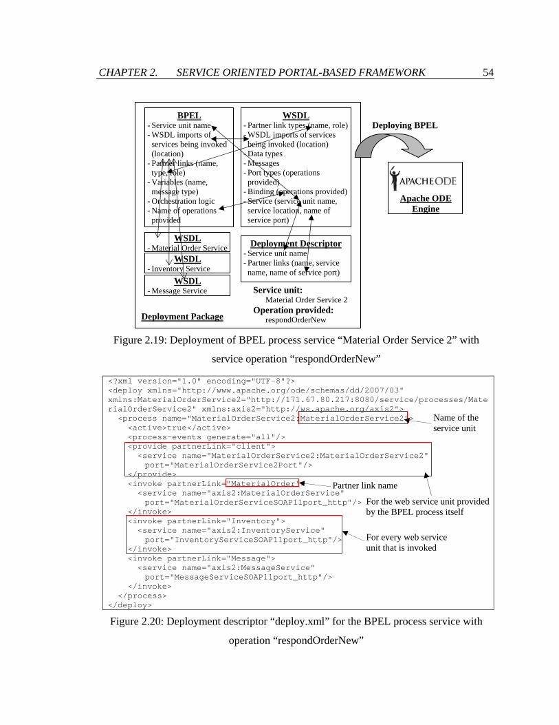
CHAPTER 2. SERVICE ORIENTED PORTAL-BASED FRAMEWORK 54
Figure 2.19: Deployment of BPEL process service “Material Order Service 2” with
service operation “respondOrderNew”
<?xml version="1.0" encoding="UTF-8"?> <deploy xmlns="http://www.apache.org/ode/schemas/dd/2007/03" xmlns:MaterialOrderService2="http://171.67.80.217:8080/service/processes/MaterialOrderService2" xmlns:axis2="http://ws.apache.org/axis2"> <process name="MaterialOrderService2:MaterialOrderService2"> <active>true</active> <process-events generate="all"/> <provide partnerLink="client"> <service name="MaterialOrderService2:MaterialOrderService2" port="MaterialOrderService2Port"/> </provide> <invoke partnerLink="MaterialOrder"> <service name="axis2:MaterialOrderService" port="MaterialOrderServiceSOAP11port_http"/> </invoke> <invoke partnerLink="Inventory"> <service name="axis2:InventoryService" port="InventoryServiceSOAP11port_http"/> </invoke> <invoke partnerLink="Message"> <service name="axis2:MessageService" port="MessageServiceSOAP11port_http"/> </invoke> </process> </deploy>
Figure 2.20: Deployment descriptor “deploy.xml” for the BPEL process service with
operation “respondOrderNew”
WSDL - Inventory Service
BPEL - Service unit name - WSDL imports of services being invoked (location)
- Partner links (name, type, role)
- Variables (name, message type)
- Orchestration logic - Name of operations provided
Deployment Descriptor - Service unit name - Partner links (name, service name, name of service port)
WSDL - Partner link types (name, role)- WSDL imports of services being invoked (location)
- Data types - Messages - Port types (operations provided)
- Binding (operations provided)- Service (service unit name, service location, name of service port)
WSDL - Material Order Service
WSDL - Message Service
Deployment Package
Service unit: Material Order Service 2 Operation provided: respondOrderNew
Deploying BPEL
Apache ODE Engine
For the web service unit provided by the BPEL process itself
For every web service unit that is invoked
Partner link name
Name of the service unit

CHAPTER 2. SERVICE ORIENTED PORTAL-BASED FRAMEWORK 55
Import
<?xml version="1.0" encoding="UTF-8" standalone="no"?> <definitions xmlns="http://schemas.xmlsoap.org/wsdl/" xmlns:plnk="http://docs.oasis-open.org/wsbpel/2.0/plnktype" xmlns:soap="http://schemas.xmlsoap.org/wsdl/soap/" xmlns:tns="http://171.67.80.217:8080/service/processes/MaterialOrderService2" xmlns:vprop="http://docs.oasis-open.org/wsbpel/2.0/varprop" xmlns:wsdl="http://ws.apache.org/axis2" name="MaterialOrderService2" targetNamespace="http://171.67.80.217:8080/service/processes/MaterialOrderService2"> <plnk:partnerLinkType name="MaterialOrderPLT"> <plnk:role name="serviceProvider" portType="wsdl:MaterialOrderServicePortType"/> </plnk:partnerLinkType> <plnk:partnerLinkType name="InventoryPTL"> <plnk:role name="serviceProvider" portType="wsdl:InventoryServicePortType"/> </plnk:partnerLinkType> <plnk:partnerLinkType name="Message"> <plnk:role name="serviceProvider" portType="wsdl:MessageServicePortType"/> </plnk:partnerLinkType> <plnk:partnerLinkType name="MaterialOrderService2"> <plnk:role name="MaterialOrderService2Provider" portType="tns:MaterialOrderService2"/> </plnk:partnerLinkType> <import location="MaterialOrderService.wsdl" namespace="http://ws.apache.org/axis2"/> <import location="InventoryService.wsdl" namespace="http://ws.apache.org/axis2"/> <import location="MessageService.wsdl" namespace="http://ws.apache.org/axis2"/> <types> <schema xmlns="http://www.w3.org/2001/XMLSchema" targetNamespace="http://171.67.80.217:8080/service/processes/MaterialOrderService2"> <element name="MaterialOrderService2Request"> <complexType> <sequence> <element name="orderId" type="string"/> <element name="confirmationNumber" type="string"/> <element maxOccurs="unbounded" name="accept" type="string"/> <element maxOccurs="unbounded" name="reject" type="string"/> </sequence> </complexType> </element> <element name="MaterialOrderService2Response"> <complexType> <sequence> <element name="notification" type="string"/> </sequence> </complexType> </element> </schema> </types> <message name="MaterialOrderService2RequestMessage"> <part element="tns:MaterialOrderService2Request" name="payload"/> </message> <message name="MaterialOrderService2ResponseMessage"> <part element="tns:MaterialOrderService2Response" name="payload"/> </message> <portType name="MaterialOrderService2"> <operation name="respondOrderNew"> <input message="tns:MaterialOrderService2RequestMessage"/> <output message="tns:MaterialOrderService2ResponseMessage"/> </operation> </portType> <binding name="MaterialOrderService2Binding" type="tns:MaterialOrderService2"> <soap:binding style="document" transport="http://schemas.xmlsoap.org/soap/http"/> <operation name="respondOrderNew"> <soap:operation soapAction= "http://171.67.80.217:8080/service/processes/MaterialOrderService2/respondOrderNew"/> <input> <soap:body use="literal"/> </input> <output> <soap:body use="literal"/> </output> </operation> </binding> <service name="MaterialOrderService2"> <port binding="tns:MaterialOrderService2Binding" name="MaterialOrderService2Port"> <soap:address location="http://171.67.80.217:8080/service/processes/MaterialOrderService2"/> </port> </service> </definitions>
Figure 2.21: WSDL document for the process service with operation “respondOrderNew”
PartnerLinkType
Types
Message
PortType
Binding
Service
Partner link type name
Location of external WSDL
Name of operation provided
Name of the service unit

CHAPTER 2. SERVICE ORIENTED PORTAL-BASED FRAMEWORK 56
While the deployment descriptor file can be easily created, it can be time-consuming to
create and edit the WSDL document that describes a BPEL process. Eclipse BPEL
Visual Designer facilitates the generation of the WSDL document. When a BPEL
process file is created in Eclipse BPEL Visual Designer, an empty WSDL document is
generated and linked to the BPEL process file. When the BPEL process file is changed,
the BPEL editor automatically alters the linked WSDL document and makes sure that
both the WSDL and BPEL files are consistent with each other. The WSDL document for
the BPEL process unit Material Order Service 2 shown in Figure 2.21 is the WSDL
document generated by Eclipse BPEL Visual Designer.
The BPEL file, deployment descriptor file, WSDL document, and external WSDL
documents are related to each other with some overlaps of information, as illustrated in
Figure 2.19. After deployment, the BPEL process acts as a standardized web service and
can be invoked by standardized SOAP messaging. As a result, the operation
“respondOrderNew” can replace the operation “respondOrder” with only minimal
changes of the JSP codes of the application portlet units. The actual service
implementation can be encapsulated and modified in a flexible manner.
2.5 Discussions of the SC Collaborator System
A collaborative system that is designed to manage construction supply chains needs (1)
low cost, (2) ability to integrate external systems and information, (3) ease of installation
and configuration, (4) ease to be connected and integrated, and (5) customizable access to
information and applications. All of these requirements are taken into consideration
when designing and implementing the SC Collaborator system.
• Low cost: The SC Collaborator system framework is developed leveraging open
source tools. These tools can be freely downloaded and easily installed.
Furthermore, these tools are widely supported in various open source

CHAPTER 2. SERVICE ORIENTED PORTAL-BASED FRAMEWORK 57
communities. Therefore, SC Collaborator provides an economical solution with
low cost for system installation and maintenance.
• Ability to integrate external systems and information: The connectivity to the
extensible computing layer enables SC Collaborator to integrate with external
systems and information. Since the application portlet units are based on the Java
framework, the SC Collaborator system can connect to databases through JDBC,
and to systems through protocols such as TCP/IP and JRMP (Java Remote
Method Protocol). If the systems and databases of trading partners are wrapped
into web services, connectivity and integration are even easier. SC Collaborator
can also obtain files and information from online sources such as web sites. This
allows dynamic responses to changes of online information. The scope of
integration in SC Collaborator is therefore not constrained to a local machine or to
a communication network that a user belongs to; instead, any information,
applications and systems that are online and available on the web can potentially
be integrated in SC Collaborator.
• Ease of installation and configuration: The SC Collaborator system can be easily
installed and reconfigured. The modular system architecture of SC Collaborator
allows flexible installation of the system components. Configuration on the
system, users, and layout can be conveniently modified using the administrative
portlet units provided on the portal user interface. System layout and service
invocation can also be conveniently altered in the JSP codes of application portlet
units. In addition, system functionality can be changed flexibly because the
internal information, applications and operations are encapsulated and deployed
as separate web service units, which can be integrated and modified easily.
Therefore, a lot of time and effort can be saved on installation and configuration.
• Ease to be connected and integrated: Ease to be connected and integrated is
fulfilled by leveraging Apache Axis2, Apache Struts, and the web portal user
interface. Many programming languages such as Java and commercial software

CHAPTER 2. SERVICE ORIENTED PORTAL-BASED FRAMEWORK 58
such as Microsoft Excel have developed the infrastructure to invoke web services
through SOAP messaging. As internal system operations can be exposed to
external systems via standardized web services protocol, information and
applications residing in the SC Collaborator system can be integrated in external
software applications. For example, a construction material supplier uses a home-
grown inventory management system in its warehouse. Suppose the supplier is
also one of the users of a SC Collaborator system which has been installed to
support collaborations with clients and suppliers regarding material procurement
and delivery. The inventory management system can be configured so that it
downloads the material orders from the SC Collaborator system every hour, and
then checks for any time conflicts and updates the production planning schedule
in an appropriate manner.
• Customizable access to information and applications: Accessibility to system
layouts and operations in SC Collaborator can be assigned to users according to
the roles, user groups, and organization the user belongs to. The access control
can also be customized to individual users. As a result, internal information,
applications and system operations in SC Collaborator are protected for trading
partners. This ensures that the right information and operations are delivered to
the right person at the right time.
2.6 Scenario Examples
To illustrate the SC Collaborator system for construction industry applications, two
example scenarios are described in the following sections. These examples demonstrate
the potential of SC Collaborator to facilitate communication among construction project
participants, and to integrate distributed web applications and systems for construction
project management.

CHAPTER 2. SERVICE ORIENTED PORTAL-BASED FRAMEWORK 59
2.6.1 Procurement Interactions
The first example is an e-Procurement scenario among interior designers, contractors and
suppliers. Many studies have shown the values of electronic procurement (e-
Procurement) in supply chain management [43, 85]. In addition to the obvious savings in
transaction cost and time, e-Procurement increases responsiveness to orders, offers
product standardization, and enhances inventory management. However, it usually takes
time to configure and establish the communication channels between buyers and sellers.
Due to its service oriented architecture, SC Collaborator allows easy and quick
integration of system users. When there is a new supplier, the system administrator
simply needs to create an account in SC Collaborator for the supplier and add the address
of the supplier’s web services to the system. The communication between trading
partners is then achieved through the standardized web services protocol.
This scenario demonstrates the integration of external applications (Microsoft Excel) and
information (production planning schedule) for e-Procurement in SC Collaborator.
Figure 2.22 shows the workflow of activities involved in this example scenario. In this
scenario, suppliers publish their product information on company online catalogs on the
Internet or an Extranet. The catalogs can be password protected so that only business
partners can access the published information. An interior designer working with a
general contractor company GenCon connects to the catalogs and selects the items (such
as furniture items) the designer needs (Figure 2.23). As the catalogs are incorporated
with Autodesk i-drop4 technology, the designer can drag and drop the items from online
catalogs directly to architectural design software Autodesk Architectural Desktop (ADT).
As illustrated in Figure 2.23, embedded item information is also dropped to the
architectural drawings.
4 Autodesk i-drop technology allows users to drag and drop contents from web pages to the drawing
interface in computer-aided design (CAD) software programs developed by Autodesk, Inc. The i-drop indicator software that enables Autodesk i-drop technology can be downloaded at http://usa.autodesk.com/adsk/servlet/index?siteID=123112&id=2753219&linkID=9240618.

CHAPTER 2. SERVICE ORIENTED PORTAL-BASED FRAMEWORK 60
Online catalog
1. Drag and drop items to CAD
Autodesk ADT
[HTTP]
2. Summarize & review materials[Java]
Microsoft Excel
3. Send proposed materials
[WS]
4. Review material lists
5. Submit purchase orders
6. Check capacity
7. Review purchase orders
8. Submit confirmation
9. Finalize procurement
[WS] [WS]Production
planning schedule
Interior Designe
rCo
ntractor
Supp
lier
Figure 2.22: Workflow in the e-Procurement scenario
Figure 2.23: Integrating online purchasing with CAD and procurement services: (1)
designers dragging items from supplier’s online catalogs to CAD drawings, (2) extracting
the embedded item information to a spreadsheet in Microsoft Excel, (3) and sending the
suggested item list to SC Collaborator for contractor to review
Floor plan in Autodesk ADT
SC Collaborator
[Web service]
[Autodesk i-drop]
XML package file: <?xml version=”1.0”?> <package xmlns=”x-schema:idrop-schema.xml”> <proxy defaultsrc=”data/bed1.jpg”> </proxy> <dataset defaultsrc=”Portrait_K1456.max”> <datasrc clipformat=”CF_IDROP.max”> <datafile src=”IK-CA-0789.max”/> </datasrc> <datasrc clipformat=”CF_IDROP.dwg”> <datafile src=”IK-CA-0789.dwg”/> </datasrc> </dataset> </package>
(1)
(2)
(3)

CHAPTER 2. SERVICE ORIENTED PORTAL-BASED FRAMEWORK 61
After selecting and adding the items to the architectural drawings, the designer extracts
the item information from Autodesk ADT to Microsoft Excel for final checking and
submission (Figure 2.23). The procurement is submitted to SC Collaborator via
standardized web services protocol for the general contractor to review. The
procurement officer in GenCon can log into the SC Collaborator system and evaluate the
material lists proposed by the designer through the portlet unit shown in Figure 2.24.
Each product item is hyperlinked to a separate window that displays the product
information and timestamps. Items that have not been included in any purchase order can
be selected and grouped together for procurement. By providing an order number, an
electronic purchase order can be easily generated and sent to the designated suppliers for
confirmation.
Figure 2.24: Contractor’s layout for review of procurement item list and submission of
electronic purchase orders
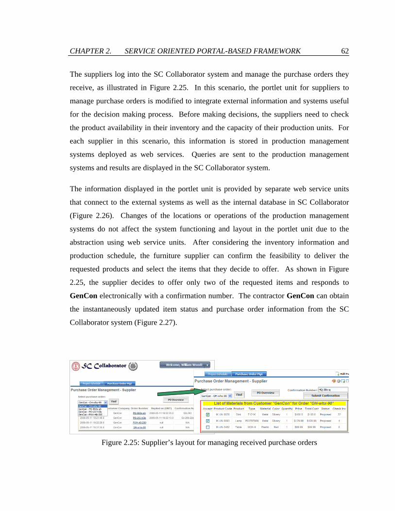
CHAPTER 2. SERVICE ORIENTED PORTAL-BASED FRAMEWORK 62
The suppliers log into the SC Collaborator system and manage the purchase orders they
receive, as illustrated in Figure 2.25. In this scenario, the portlet unit for suppliers to
manage purchase orders is modified to integrate external information and systems useful
for the decision making process. Before making decisions, the suppliers need to check
the product availability in their inventory and the capacity of their production units. For
each supplier in this scenario, this information is stored in production management
systems deployed as web services. Queries are sent to the production management
systems and results are displayed in the SC Collaborator system.
The information displayed in the portlet unit is provided by separate web service units
that connect to the external systems as well as the internal database in SC Collaborator
(Figure 2.26). Changes of the locations or operations of the production management
systems do not affect the system functioning and layout in the portlet unit due to the
abstraction using web service units. After considering the inventory information and
production schedule, the furniture supplier can confirm the feasibility to deliver the
requested products and select the items that they decide to offer. As shown in Figure
2.25, the supplier decides to offer only two of the requested items and responds to
GenCon electronically with a confirmation number. The contractor GenCon can obtain
the instantaneously updated item status and purchase order information from the SC
Collaborator system (Figure 2.27).
Figure 2.25: Supplier’s layout for managing received purchase orders

CHAPTER 2. SERVICE ORIENTED PORTAL-BASED FRAMEWORK 63
SC Collaborator
Web service
unit
DB
Web service
unit
Production planning schedule
Web service interface
Supplier
Figure 2.26: Connection to internal and external information and applications in the
portlet unit that suppliers manage and evaluate received purchase orders
Figure 2.27: Contractor’s layout showing updated item status and purchase order
information

CHAPTER 2. SERVICE ORIENTED PORTAL-BASED FRAMEWORK 64
2.6.2 Project Rescheduling
The second scenario is based on data collected from a completed construction project of a
supermarket of 11,500 square meters in Boras, Sweden (Figure 2.28). The project started
in April 2007 and finished in April 2008. In this project, the main contractor hired 21
subcontractors. Since the project was heavily dependent on subcontractors,
communication and collaboration among the general contractor and subcontractors were
crucial to the success of the project.
Figure 2.28: Floor plan and finished layout of the supermarket in Boras, Sweden

CHAPTER 2. SERVICE ORIENTED PORTAL-BASED FRAMEWORK 65
One of the major problems in the project reported by the general contractor was the
schedule delay by the subcontractors, which causes the project manager to reschedule
almost every day. Turnkey-type of contracts were used in the project. In other words,
material procurement, delivery and installation were performed by the subcontractors
themselves. The general contractor was not involved in any of these activities.
Therefore, poor communication and coordination among the general contractors and
subcontractors could prevent the project manager from gathering all the necessary
information for making the right decisions in schedule change, hindering the rescheduling
and project planning processes.
To limit the scope, the period between May 2007 and August 2007 was extracted for
testing purposes. In this period, the construction site was divided into five areas (i.e.
major parts 1, 2, 3, entry area, and loading area) in most processes such as ground works,
piling works and foundation works. There were 38 activities in total in this period,
involving five subcontractors. Figure 2.29 shows a portion of the project schedule.
Figure 2.29 also illustrates some of the activity dependencies in the period. This implies
the interdependencies and constraints of the site areas as well as the subcontractors. This
scenario focuses on the suppliers of a concrete works subcontractor, Muniak.
Information such as material delivery and activity start time is crucial for project
rescheduling. The SC Collaborator system provides a platform for integrating this
information from suppliers, subcontractors and general contractor. The flows of
information and interactions are as follows (Figure 2.30). In the scenario, production
status information and expected delivery time information were reported to
corresponding subcontractors by the suppliers (Figure 2.31). By sharing the current
status and future forecast of production, suppliers could let customers be aware of any
potential production problems ahead of time and be able to mitigate the problems.
Sharing of current delivery status and expected delivery time allowed the contractors to
plan for the on-site product verification and storage and to evaluate their schedule
feasibility. General contractor and subcontractors could monitor the production and
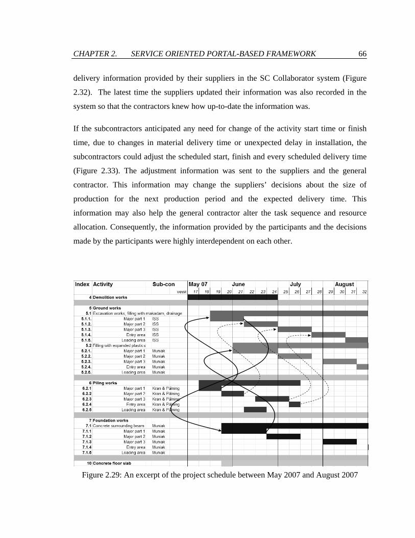
CHAPTER 2. SERVICE ORIENTED PORTAL-BASED FRAMEWORK 66
delivery information provided by their suppliers in the SC Collaborator system (Figure
2.32). The latest time the suppliers updated their information was also recorded in the
system so that the contractors knew how up-to-date the information was.
If the subcontractors anticipated any need for change of the activity start time or finish
time, due to changes in material delivery time or unexpected delay in installation, the
subcontractors could adjust the scheduled start, finish and every scheduled delivery time
(Figure 2.33). The adjustment information was sent to the suppliers and the general
contractor. This information may change the suppliers’ decisions about the size of
production for the next production period and the expected delivery time. This
information may also help the general contractor alter the task sequence and resource
allocation. Consequently, the information provided by the participants and the decisions
made by the participants were highly interdependent on each other.
Figure 2.29: An excerpt of the project schedule between May 2007 and August 2007

CHAPTER 2. SERVICE ORIENTED PORTAL-BASED FRAMEWORK 67
Supp
liers 1. Report
production
2. Check scheduled delivery time
3. Determine number of production for next period and expected delivery time
Sub-
cont
ract
ors 1. For each task,
review all materials delivery time
2. Adjust scheduled start, finish and every scheduled delivery time
3. Report start, finish and progress
Gen
eral
Con
trac
tor 1. Review
change of scheduled start and finish
2. Consistency check & update schedule
Figure 2.30: Information flows and interactions in the rescheduling process
Figure 2.31: Supplier’s layout for production reporting
Delivery time requested by contractor
Delivery time estimated by supplier can be changed
Notify contractor when product is delivered
Reporting current status and future forecast of production

CHAPTER 2. SERVICE ORIENTED PORTAL-BASED FRAMEWORK 68
Figure 2.32: Subcontractor’s layout for monitoring material production and delivery
Figure 2.33: Subcontractor’s layout for activity review and adjustment
Subcontractors can change the estimated start time and finish time of the task they are responsible for
Reporting of current progress
Showing the delivery status of the materials required for this task

CHAPTER 2. SERVICE ORIENTED PORTAL-BASED FRAMEWORK 69
Transparency among the suppliers, subcontractors and general contractor is important for
construction supply chain management. The general contractor reported that they had no
idea about the situations and problems of materials and therefore could only keep pushing
the subcontractors, while several subcontractors in the project even did not have all the
information from their suppliers. The SC Collaborator system allows instantaneous
sharing and analysis of information, adding values to the entire supply chain. Different
cases of collaboration and information transparency were tested using the SC
Collaborator system. It showed that the benefits of information sharing in this scenario
can be significant. For example, there was a material production and delivery delay of
one week (five working days) starting from Day 1 of Week 20 for a sandwich concrete
element called Siroc. The element was required for the activity “7.1.1 foundation works
– concrete surrounding beam – major part 1.” The activity required two more materials –
1,121 m3 of concrete and 2,388 m2 of form material (wood). The form material was
delivered to the construction site every working day. There were several constraints that
had to be satisfied: every delivery must be confirmed at least three working days before
the delivery time. In addition, product type, configuration, amount, and delivery time
cannot be changed after confirmation.
Figure 2.34 is a plot of the inventory on site of the form material over time. The area
under each curve multiplied by per-unit per-day holding cost represents the total
inventory holding cost of the form material due to delivery delay of the material Siroc,
which happened in Day 1 of Week 20. If the Siroc supplier notified the subcontractor
Muniak of the delay at least three days earlier, Muniak could contact the supplier of the
form material immediately and delay the delivery for one week. The activity 7.1.1 could
also be postponed, allowing the general contractor and other subcontractors to modify the
project schedule and reallocate resources. If Muniak knew the delay one day earlier than
delivery time, the inventory holding cost it would incur was more than double the cost it
would incur if it knew two days earlier. If the Siroc supplier did not notify Muniak of
the delay, either due to unwillingness to report or lack of communication channels, the
inventory holding cost could be tremendous. Therefore, although information sharing

CHAPTER 2. SERVICE ORIENTED PORTAL-BASED FRAMEWORK 70
between trading partners looks simple, it can aid decision making and add significant
values to each supply chain member.
People often are not aware of the changes in the materials or schedules and do not react
to the changes promptly, leading to time lags of the information flowing among project
participants. The time lags can accumulate along a supply chain and result in significant
impacts. Therefore, message notifications and automated responses can support efficient
supply chain management. In this scenario, for instance, basic service units were
integrated and orchestrated into a composite service unit to facilitate automated response
and notification upon changes of material delivery. When a supplier changed the
estimated delivery time of a product item using the production reporting application
portlet unit (Figure 2.31), the composite service operation “changeDeliveryEstiamte” is
triggered.
0
50
100
150
200
250
300
350
400
Wk 19 D5
Wk 20 D1
Wk 20 D2
Wk 20 D3
Wk 20 D4
Wk 20 D5
Wk 21 D1
Wk 21 D2
Wk 21 D3
Wk 21 D4
Wk 21 D5
Wk 22 D1
Wk 22 D2
>=3 days notification2 days notification1 day notificationNo notification
Figure 2.34: Inventory (in m2) of form material (wood) under different supply delay
conditions

CHAPTER 2. SERVICE ORIENTED PORTAL-BASED FRAMEWORK 71
As illustrated in Figure 2.35, the operation combines the functionality of various basic
service operations from the Material Order Service, Message Service, and Project
Schedule Service. First, the operation notifies the buyer of the change in item delivery
time and checks the impact of the change to the affected task. If the impact is high and
the start time of the affected task needs to be changed (postponed in most cases), the
operation “changeDeliveryEstimate” modifies the task schedule, alters the target delivery
time of the other product items involved in the affected task, and notifies the general
contractor, subcontractors, and suppliers impacted. This shows that business tasks can be
customized and automated conveniently in a service oriented framework such as SC
Collaborator.
2.7 Summary
This chapter describes a prototype service oriented portal-based system, SC Collaborator,
designed for construction supply chain integration and collaboration. Open standards and
open source technologies are leveraged for the system implementation. The SC
Collaborator system provides a single point of access to distributed information,
applications and services among scattered supply chain members. It is modular, flexible,
secure, and easy to install and reconfigure, which make the SC Collaborator system a
desirable means for companies in the construction industry. The system also allows
interoperation among applications because programs written in different languages and
operating on different systems can be integrated via standardized web services protocol.
The system consists of four major components. The communication layer allows users to
connect to the system using web browsers, wireless devices, and web services. The
portal-based user interface manages the system configuration and layout. The business
applications layer performs deployment, invocation, and orchestration of web service
units. The back-end database stores and provides the information that supports the

CHAPTER 2. SERVICE ORIENTED PORTAL-BASED FRAMEWORK 72
system and various application operations. Based on the characteristics of construction
supply chains and the study in literatures, we have summarized five desirable sytem
features for construction supply chain integration and collaboration as described in
Section 1.2. The SC Collaborator system fulfills all these five system features.
Figure 2.35: BPEL process for the operation “changeDeliveryEstimate”
Message Service
Material Order Service
Project Schedule Service
Message ServiceMaterial Order Service
Material Order Service
Message Service
- itemId - new estimated delivery time
- notification
[If the item is essential to the affected task]

CHAPTER 2. SERVICE ORIENTED PORTAL-BASED FRAMEWORK 73
Two example scenarios have been presented to illustrate the potential of the SC
Collaborator system to extend functionality and to integrate partners in construction
projects. The first one is an e-Procurement scenario which involves designers,
contractors and suppliers. In this scenario, online catalogs, architectural design software,
SC Collaborator, and production and inventory planning systems are integrated to
facilitate the procurement process in construction projects. The second one is a scenario
based on a real construction project of a supermarket in Boras, Sweden. The
rescheduling problem among general contractor, subcontractors and material suppliers
has been studied. The importance of transparency in an integrated construction supply
chain which can be enabled by the SC Collaborator system has been illustrated in the
chapter.

Chapter 3
Supply Chain Modeling and Performance Monitoring
3.1 Introduction
The planning and management of supply chains require properly specifying the
participating members and identifying the relationships among them. This task is
especially challenging in the construction industry because construction supply chains are
complex in structure and often composed of a large number of participants who work
together in a project-based temporary manner. Construction projects typically involve
tens and hundreds of companies, supplying materials, components, and a wide range of
construction services [28]. Modeling the structure of participants involved in a
construction supply chain can help understand the complexity and the organization in a
supply chain [74]. Supply chain network models also facilitate the identification of
bottlenecks and provide the basis for supply chain re-configuration and re-engineering.
There are very few standard methods or frameworks for representing and modeling
supply chain structures. Supply chain structures are commonly recorded as tables that

CHAPTER 3. SUPPLY CHAIN MODELING AND MONITORING 75
enlist the members of a supply chain, or represented as network diagrams that show the
supply chain members as well as the links between them. Lambert and Cooper [52]
proposed a mapping of supply chain structures using three primary attributes: members of
the supply chain, structural dimensions, and types of business processes between the
members. However, these methods do not provide a direct migration from the modeling
of supply chain structures to the modeling of the business operations.
There are two commonly used supply chain modeling frameworks that provide guidelines
to systematically map the relationships of companies and specify the operations involved
in a supply chain. The Supply Chain Model framework introduced by the Global Supply
Chain Forum (GSCF) is built on eight key business processes that are both cross-
functional and cross-organizational in nature [51]. As illustrated in Figure 3.1, the eight
processes are customer relationship management, supplier relationship management,
customer service management, demand management, order fulfillment, product
development and commercialization, manufacturing flow management, and returns
management. Each process is managed by a cross-functional team, including
representatives from logistics, production, purchasing, finance, marketing, and research
and development. The Supply Chain Model framework provides a granular framework
to model the cross-departmental interactions in every process along a supply chain.
However, the majority of construction companies are small and medium enterprises
(SMEs). According to a study on the construction industry in United Kingdom [28], for
example, about 83% of the private contracting companies employ three or less workers
while 98% of the companies employ 24 or less workers. Construction companies often
do not have a clear boundary between business functional units. Employees in
construction companies usually work on a project basis instead of a business functional
basis. Therefore, the Supply Chain Model framework that describes the interactions
across internal business functional units is not suitable for modeling construction supply
chains.

CHAPTER 3. SUPPLY CHAIN MODELING AND MONITORING 76
Figure 3.1: The Supply Chain Model framework [51] introduced by the Global Supply
Chain Forum (GSCF)
The other framework is the Supply Chain Operations Reference (SCOR) modeling
framework established by the Supply Chain Council for supply chain standardization,
measurement, and improvement [91]. The SCOR modeling framework is based on five
key supply chain processes – Plan, Source, Make, Deliver, and Return. The SCOR
modeling framework is hierarchically structured into four levels, with increasing details
at each level. Construction supply chains often do not have a standard and well
structured configuration. Members may not be involved in both the material flows and
the information flows of the procurement, manufacturing, and distribution activities in
construction supply chains. Since the SCOR framework is generic and can be used to
model supply chains of various types and scales, the framework is suitable for modeling
various construction supply chains of different complexity. The material flows and
information flows in a supply chain are represented separately in the SCOR framework.
Therefore, the SCOR framework is employed for modeling construction supply chains in
this study.
The SCOR framework has been widely used to model supply chain network structures
and operations for strategic planning purposes [42]. However, the SCOR framework is

CHAPTER 3. SUPPLY CHAIN MODELING AND MONITORING 77
seldom leveraged for the design and implementation of information systems for supply
chain management. Furthermore, while performance monitoring is critical to the
measurement and improvement of supply chains, there have been little efforts focused on
performance monitoring systems for construction supply chain management. This
chapter discusses the modeling of construction supply chains using the SCOR
framework. Furthermore, this chapter describes the development of a supply chain
performance monitoring system by incorporating the SCOR models into the service
oriented SC Collaborator framework described in Chapter 2.
The supply chain models for a demonstration application presented in this chapter are
developed using a retrospective case study of the mechanical, electrical and plumbing
(MEP) processes in a student center construction project. There are altogether 524
distinct process-based performance metrics recommended in SCOR [91]. Since the MEP
case example is focused on the procurement and delivery processes, the metrics selected
in this study are the process cycle times, documentation accuracy, and product conditions
upon arrival. A model-based service oriented approach is adopted in the development of
the performance monitoring system. First, the supply chain models are transformed into
process execution files by leveraging Business Process Modeling Notation (BPMN) [78]
and Business Process Execution Language (BPEL) [80]. The BPEL process execution
files are then incorporated in the monitoring system, which is built on SC Collaborator.
This chapter is organized as follows. Section 3.2 briefly describes the SCOR framework.
Section 3.3 presents the MEP processes in the construction project we studied and
illustrates the modeling of the MEP supply chains using the SCOR framework. Section
3.4 demonstrates the implementation of the prototype supply chain performance
monitoring system and discusses the usage of performance metrics. Section 3.4 also
presents a service oriented approach to implementation of a system framework based on
SCOR models. Specially, the conversion of supply chain models into BPEL executable
files and the incorporation of the BPEL files in the service oriented system SC
Collaborator are illustrated in Section 3.4. Section 3.5 shows the system with the
CHAPTER 3. SUPPLY CHAIN MODELING AND MONITORING 78
construction project example. Section 3.6 summarizes the chapter and discusses the
limitations and potentials.
3.2 Supply Chain Operations Reference (SCOR) Model
The Supply Chain Operations Reference (SCOR) modeling framework was initially
developed by Supply Chain Council in 1996. The current version is the SCOR model
version 9.0, which was released in 2008 [91]. The framework provides a systematic
approach to describe, characterize, and evaluate complex supply chain processes.
Standardization of business processes is necessary to allow the communication and
integration between business partners of the supply network [38]. The SCOR model is a
process reference model for standardization purposes. The model attempts to capture
business operations including (1) customer interactions, from order entry through paid
invoice, (2) product transactions, from supplier’s supplier to customer’s customer, and (3)
market interactions, from the understanding of aggregate demand to the fulfillment of
each order [91].
The SCOR modeling framework is based on five basic management processes in supply
chains – Plan, Source, Make, Deliver, and Return – to meet planned and actual demand
(Figure 3.2). Plan includes processes that balance resources to establish plans that best
meet the requirements of a supply chain and its sourcing, production, delivery, and return
activities. Source includes processes that manage the procurement, delivery, receipt, and
transfer of raw material items, subassemblies, products, and services. Make includes
processes that transform products to a finished state. Deliver includes processes that
provide finished goods and services, including order management, transportation
management, and distribution management. Return includes post-delivery customer
support and processes that are associated with returning or receiving returned products.

CHAPTER 3. SUPPLY CHAIN MODELING AND MONITORING 79
Figure 3.2: SCOR Level 1 modeling [91]
The SCOR framework allows users to model supply chain structures and relationships in
a progressive and systematic manner. There are four levels of model development in the
SCOR framework (Figure 3.3). Level 1 modeling provides a broad definition of the
scope and content for the SCOR model (Figure 3.2). Level 2 modeling divides the five
basic management processes into process categories, which allow companies to describe
the configuration of their supply chains. Table 3.1 shows the Level 2 process categories
described in the SCOR framework. Level 2 models conceptually specify the relationship
and interactions among supply chain members. The conceptual specification can be
extended to describe the process workflow through Level 3 modeling.
Level 3 modeling provides companies with the information for detailed planning and
setting goals. The SCOR framework offers a guideline of the inputs and outputs for each
Level 3 process element. As an example, Figure 3.4 shows a Level 3 process “S1.1
Schedule Product Deliveries.” As shall be discussed in Section 3.4.1, Level 3 processes
provide the basis for defining the supply chain performance metrics. The Level 3
processes for process type Source, Make, and Deliver are illustrated in Table 3.2, Table
3.3, and Table 3.4 respectively.

CHAPTER 3. SUPPLY CHAIN MODELING AND MONITORING 80
Figure 3.3: Four levels of SCOR business processes [91]
Figure 3.4: Inputs and outputs for Level 3 process “S1.1 Schedule Product Deliveries”
Level # Description Schematic
SCO
R M
odel
1 Top Level (Process Types)
2 Configuration
Level (Process
Categories)
3 Process Element
Level (Decompose Processes)
4 Implementation
Level (Decompose
Process Elements)
Plan Deliver MakeSource
Return Return
Plan
P5 P4 P3P2P1
P1.1 Identify, Prioritize, and
Aggregate Supply-Chain Requirements
P1.4 Establish and Communicate Supply-Chain
Plans P1.2
Identify, Assess, and Aggregate Supply-Chain
Resources
P1.3 Balance Supply-Chain Resources
with Supply-Chain Requirements
Not
Incl
uded
in
SC
OR
Doc
P1: Plan Supply Chain; P2: Plan Source; P3: Plan Make; P4: Plan Deliver; P5: Plan Return
S1.1 Schedule Product
Deliveries
Inputs Sourcing Plans P2.4 Replenishment Signal M1.2, M2.2, M3.3, D1.3, D2.3, D3.3 Return Inventory Transfer Data DR1.4, DR2.4, DR3.3, DR3.4 Production Schedule M1.2, M2.1, M3.2
Outputs Product On Order P2.2 Scheduled Receipts S1.2, S3.4, M1.1, M2.1, M3.2, D1.8, D4.2 Procurement Signal (Supplier)

CHAPTER 3. SUPPLY CHAIN MODELING AND MONITORING 81
Table 3.1: SCOR Level 2 process categories
Level 1 Process Type Level 2 Process Category PLAN P1: Plan Supply Chain
P2: Plan Source P3: Plan Make P4: Plan Deliver P5: Plan Return
SOURCE S1: Source Stocked Product S2: Source Make-to-Order Product S3: Source Engineer-to-Order Product
MAKE M1: Make-to-Stock M2: Make-to-Order M3: Engineer-to-Order
DELIVER D1: Deliver Stocked Product D2: Deliver Make-to-Order Product D3: Deliver Engineer-to-Order Product D4: Deliver Retail Product
RETURN SR1: Source Return Defective Product SR2: Source Return Maintenance, Repair, Operations (MRO) Product SR3: Source Return Excess Product DR1: Deliver Return Defective Product DR2: Deliver Return Maintenance, Repair, Operations (MRO) Product DR3: Deliver Return Excess Product
Table 3.2: SCOR Level 3 process elements for “Source”
S1: Source Stocked Product S2: Source Make-to-Order Product
S3: Source Engineer-to-Order Product
S1.1: Schedule Product Deliveries
S1.2: Receive Product S1.3: Verify Product S1.4: Transfer Product S1.5: Authorize Supplier
Payment
S2.1: Schedule Product Deliveries
S2.2: Receive Product S2.3: Verify Product S2.4: Transfer Product S2.5: Authorize Supplier
Payment
S3.1: Identify Sources of Supply S3.2: Select Final Supplier(s) and
Negotiate S3.3: Schedule Product Deliveries S3.4: Receive Product S3.5: Verify Product S3.6: Transfer Product S3.7: Authorize Supplier Payment

CHAPTER 3. SUPPLY CHAIN MODELING AND MONITORING 82
Table 3.3: SCOR Level 3 process elements for “Make”
M1: Make-to-Stock M2: Make-to-Order M3: Engineer-to-Order M1.1: Schedule Production
Activities M1.2: Issue Product M1.3: Produce and Test M1.4: Package M1.5: Stage Product M1.6: Release Product to
Deliver M1.7: Waste Disposal
M2.1: Schedule Production Activities
M2.2: Issue Product M2.3: Produce and Test M2.4: Package M2.5: Stage Product M2.6: Release Finished Product
to Deliver M2.7: Waste Disposal
M3.1: Finalize Engineering M3.2: Schedule Production
Activities M3.3: Issue Product M3.4: Produce and Test M3.5: Package M3.6: Stage Product M3.7: Release Product to Deliver M3.8: Waste Disposal
Table 3.4: SCOR Level 3 process elements for “Deliver”
D1: Deliver Stocked Product
D2: Deliver Make-to-Order Product
D3: Deliver Engineer-to-Order Product
D4: Deliver Retail Product
D1.1: Process Inquiry and Quote
D1.2: Receive, Enter and Validate Order
D1.3: Reserve Inventory and Determine Delivery Date
D1.4: Consolidate Orders
D1.5: Build Loads D1.6: Route Shipments D1.7: Select Carriers and
Rate Shipments D1.8: Receive Product
from Source or Make D1.9: Pick Product D1.10: Pack Product D1.11: Load Product and
Generate Shipping Docs
D1.12: Ship Product D1.13: Receive and
Verify Product by Customer
D1.14: Install Product D1.15: Invoice
D2.1: Process Inquiry and Quote
D2.2: Receive, Configure, Enter and Validate Order
D2.3: Reserve Resources and Determine Delivery Date
D2.4: Consolidate Orders
D2.5: Build Loads D2.6: Route Shipments D2.7: Select Carriers
and Rate Shipments D2.8: Receive Product
from Source or Make D2.9: Pick Product D2.10: Pack Product D2.11: Load Product
and Generate Shipping Docs
D2.12: Ship Product D2.13: Receive and
Verify Product by Customer
D2.14: Install Product D2.15: Invoice
D3.1: Obtain and Respond to RFP/RFQ
D3.2: Negotiate and Receive Contract
D3.3: Enter Order, Commit Resources and Launch Program
D3.4: Schedule Installation
D3.5: Build Loads D3.6: Route Shipments D3.7: Select Carriers and
Rate Shipments D3.8: Receive Product
from Source or Make D3.9: Pick Product D3.10: Pack Product D3.11: Load Product and
Generate Shipping Docs
D3.12: Ship Product D3.13: Receive and
Verify Product by Customer
D3.14: Install Product D3.15: Invoice
D4.1: Generate Stocking Schedule
D4.2: Receive Product at the Store
D4.3: Pick Product from Backroom
D4.4: Stock Shelf D4.5: Fill Shopping
Cart D4.6: Checkout D4.7: Deliver
and/or install

CHAPTER 3. SUPPLY CHAIN MODELING AND MONITORING 83
Level 4 modeling focuses on implementation. Since SCOR Level 4 models are unique to
each company, the specific elements at this level are not defined within the SCOR
framework. In Level 4 modeling, users need to design the implementation details of each
Level 3 process to meet their own needs. Through the four levels of development, the
SCOR models can be extended to capture and represent complex interactions among
supply chain partners. Therefore, the SCOR framework is a useful tool for modeling
construction supply chains, which usually involve many organizations and are complex in
nature. The application of the SCOR framework to model construction supply chains is
illustrated in the next section.
3.3 Modeling of Construction Supply Chains Using SCOR Framework: A Case Example
In this chapter, a construction project of a two-storey high school student center is used as
a case example (Figure 3.5). Specifically, the mechanical, electrical and plumbing
(MEP) supply chains of the project have been studied retrospectively and modeled based
on the information from the documents provided by and the interviews conducted with
the general contractor, subcontractors, and suppliers. The buyer-supplier relationships in
a construction project can differ from project to project, organization to organization, and
product to product. However, similar patterns are observed in the buyer-supplier
interactions and configuration of supply chains among various organizations and products
in the MEP processes of the project. Although the supply chain modeling is
demonstrated only with the MEP supply chains, the framework can be potentially applied
and extended to other kinds of supply chains in construction projects of various scales
and types.

CHAPTER 3. SUPPLY CHAIN MODELING AND MONITORING 84
Figure 3.5: 3D model of the two-storey high school student center
3.3.1 Case Example
The student center in the example construction project is a two-storey building with a 650
fixed-seat auditorium, a 350 seat dining hall with a full commercial kitchen and server,
three bathrooms, and eight sophisticated science classrooms. The construction project
started in May 2008 and was planned to finish by December 2009. To minimize the
impact of the construction on student activities on campus, the construction site was kept
to minimal. The stocking space on site was limited in size and needed to change
locations occasionally over the project time. Early delivery of materials leading to long-
time stocking was not recommended in order to free up the construction site space and to
avoid double material handling. Therefore, the general contractor heavily emphasized
Just-in-Time material delivery in the project.
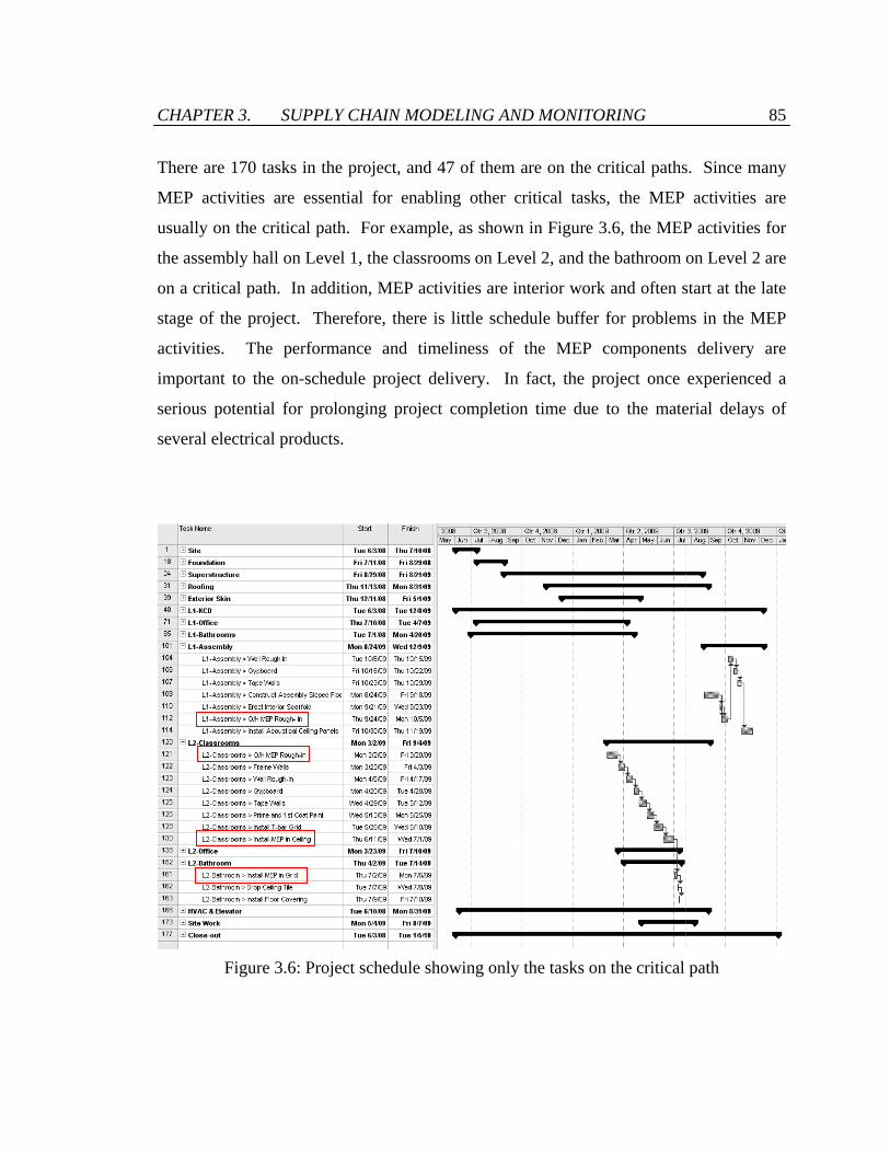
CHAPTER 3. SUPPLY CHAIN MODELING AND MONITORING 85
There are 170 tasks in the project, and 47 of them are on the critical paths. Since many
MEP activities are essential for enabling other critical tasks, the MEP activities are
usually on the critical path. For example, as shown in Figure 3.6, the MEP activities for
the assembly hall on Level 1, the classrooms on Level 2, and the bathroom on Level 2 are
on a critical path. In addition, MEP activities are interior work and often start at the late
stage of the project. Therefore, there is little schedule buffer for problems in the MEP
activities. The performance and timeliness of the MEP components delivery are
important to the on-schedule project delivery. In fact, the project once experienced a
serious potential for prolonging project completion time due to the material delays of
several electrical products.
Figure 3.6: Project schedule showing only the tasks on the critical path
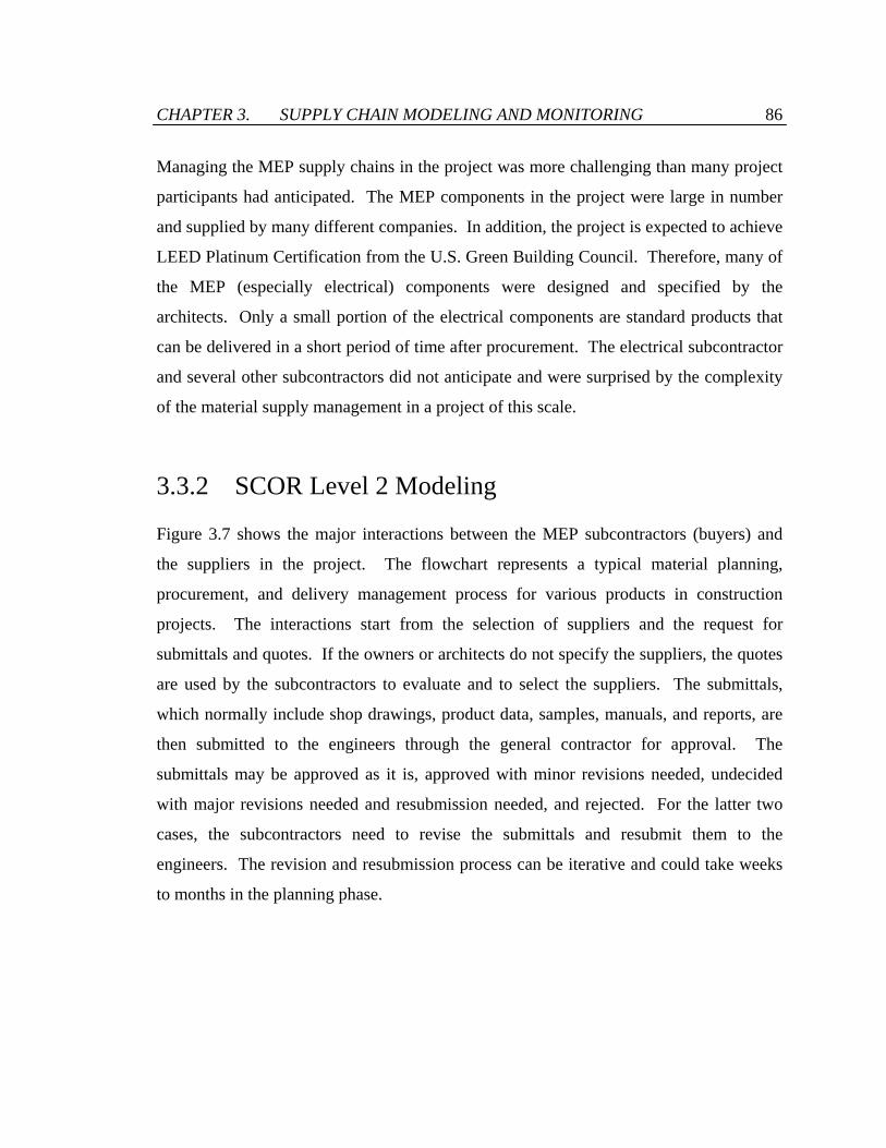
CHAPTER 3. SUPPLY CHAIN MODELING AND MONITORING 86
Managing the MEP supply chains in the project was more challenging than many project
participants had anticipated. The MEP components in the project were large in number
and supplied by many different companies. In addition, the project is expected to achieve
LEED Platinum Certification from the U.S. Green Building Council. Therefore, many of
the MEP (especially electrical) components were designed and specified by the
architects. Only a small portion of the electrical components are standard products that
can be delivered in a short period of time after procurement. The electrical subcontractor
and several other subcontractors did not anticipate and were surprised by the complexity
of the material supply management in a project of this scale.
3.3.2 SCOR Level 2 Modeling
Figure 3.7 shows the major interactions between the MEP subcontractors (buyers) and
the suppliers in the project. The flowchart represents a typical material planning,
procurement, and delivery management process for various products in construction
projects. The interactions start from the selection of suppliers and the request for
submittals and quotes. If the owners or architects do not specify the suppliers, the quotes
are used by the subcontractors to evaluate and to select the suppliers. The submittals,
which normally include shop drawings, product data, samples, manuals, and reports, are
then submitted to the engineers through the general contractor for approval. The
submittals may be approved as it is, approved with minor revisions needed, undecided
with major revisions needed and resubmission needed, and rejected. For the latter two
cases, the subcontractors need to revise the submittals and resubmit them to the
engineers. The revision and resubmission process can be iterative and could take weeks
to months in the planning phase.
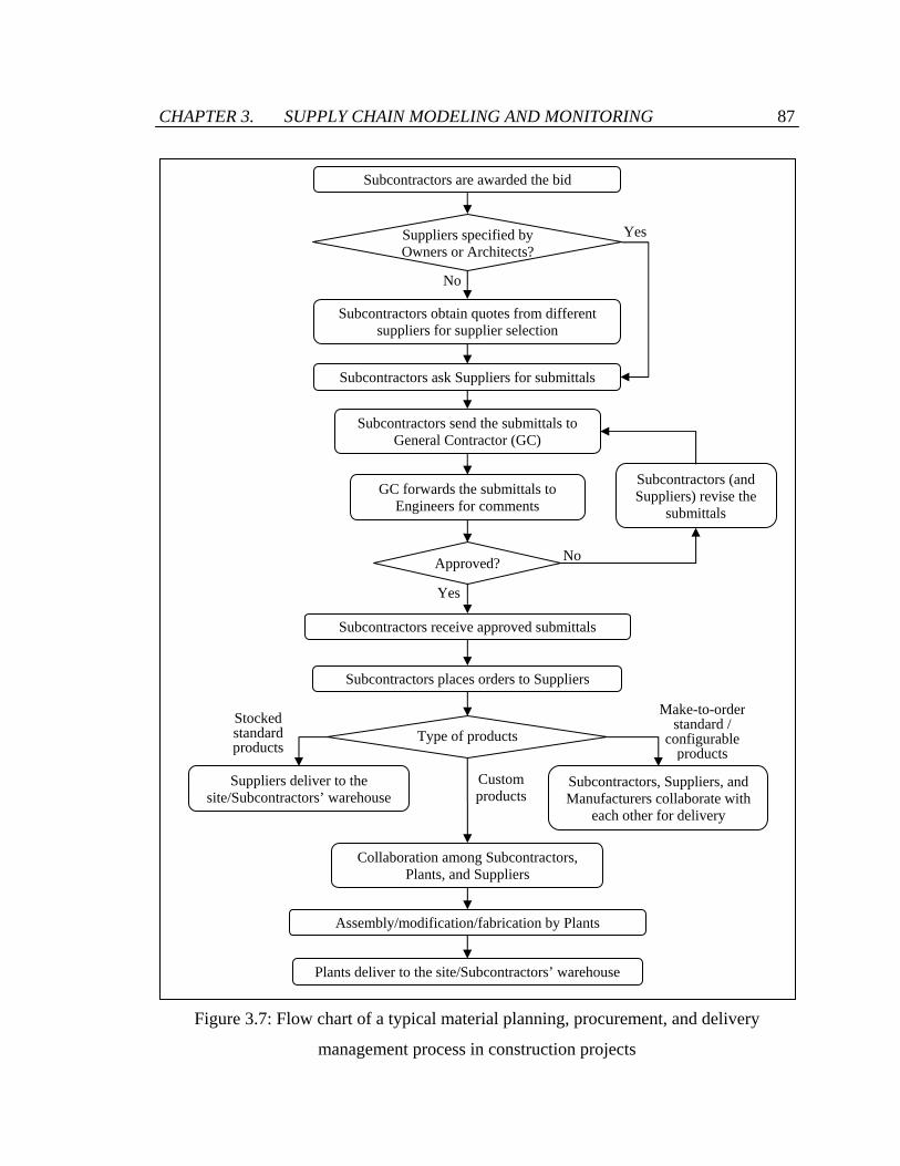
CHAPTER 3. SUPPLY CHAIN MODELING AND MONITORING 87
Figure 3.7: Flow chart of a typical material planning, procurement, and delivery
management process in construction projects
Subcontractors are awarded the bid
Subcontractors obtain quotes from different suppliers for supplier selection
Subcontractors ask Suppliers for submittals
Subcontractors send the submittals to General Contractor (GC)
GC forwards the submittals to Engineers for comments
Subcontractors receive approved submittals
Approved?
Yes
Subcontractors (and Suppliers) revise the
submittals
Yes
No
No
Subcontractors places orders to Suppliers
Type of products
Suppliers deliver to the site/Subcontractors’ warehouse
Subcontractors, Suppliers, and Manufacturers collaborate with
each other for delivery
Assembly/modification/fabrication by Plants
Collaboration among Subcontractors, Plants, and Suppliers
Plants deliver to the site/Subcontractors’ warehouse
Stocked standard products
Make-to-orderstandard /
configurable products
Custom products
Suppliers specified by Owners or Architects?

CHAPTER 3. SUPPLY CHAIN MODELING AND MONITORING 88
In the material procurement and delivery management phase in the student center
construction project, the interactions along the MEP supply chains show three major
patterns according to the nature of products. For high-demand standard commodity
products such as wires, tubing, bolts, and nuts that subcontractors purchase from
distributors (suppliers), the suppliers usually keep stocks of such products to meet
anticipated orders. Therefore, the suppliers usually can deliver the products in a short
time once they receive the purchase orders. The second type is standard and configurable
products that have low turnover rate and/or high inventory cost, for instance, light
fixtures and switchgears. Products of this type are produced only after customers'
purchase orders are received, or so-called “made-to-order.” The third type is products
that are specially designed, engineered, and customized by the owners, architects,
engineers, or subcontractors. One example is customized ductwork. Close interactions
and collaborations among the subcontractors, the plants, and the suppliers are often
required in the design, engineering, sourcing, and delivery processes. In the following
subsections, the high-level SCOR Level 2 modeling of the information flows and
material flows for these three types of products is illustrated. The supply chain models
are then extended to create supply chain process maps with greater details through the
SCOR Level 3 and Level 4 modeling in Section 3.3.3.
3.3.2.1 Stocked Standard Products
Some standard products such as wires and tubing are maintained in a finished goods state
and kept in stocks in suppliers’ inventory prior to the receipt of a customer order. These
products usually have high demand and low inventory cost. Suppliers procure according
to sales forecast, so products are produced before the suppliers receive order. Supply
chains of this type are inventory driven. Unsatisfied orders usually become lost sales as
alternative suppliers can often be found.

CHAPTER 3. SUPPLY CHAIN MODELING AND MONITORING 89
Figure 3.8: SCOR Level 2 model for a typical construction supply chain for stocked
standard products
Construction supply chains for stocked standard products involve foremen in the
construction site, subcontractors, distributors, and manufacturers. Figure 3.8 shows the
SCOR Level 2 model for this type of supply chains. The dotted lines and the solid lines
represent the information flows and the material flows respectively. The information
flows start from the subcontractors’ headquarters, where purchase orders are sent. There
are two alternative material flow paths. Products are often delivered to the construction
site at the time designated by the subcontractors. In some cases, subcontractors hope to
better control the material delivery time and practice just-in-time delivery on site. These
subcontractors prefer the suppliers first delivering the products to the subcontractors'
warehouses and manage the products themselves.
3.3.2.2 Make-to-order Standard / Configurable Products
Products of this type include products that are built to a specific design and the products
that are manufactured, assembled, or configured from standard parts or subassemblies.
Suppliers prefer make-to-order due to various reasons. Suppliers of products such as
(P1: Plan Supply Chain; P2: Plan Source; P4: Plan Deliver; S1: Source Stocked Product; D1: Deliver Stocked Product)
D1 S1 D1
P4
P2
P1
P4
S1 D1S1
Manufacturers Distributors Subcontractors’
headquarters Subcontractors’
warehouses Construction site
S1
Information flow Material flow
CHAPTER 3. SUPPLY CHAIN MODELING AND MONITORING 90
light fixtures usually do not keep stocks of their products because they often publish a
wide variety of products in catalogs and it is hard for them to anticipate the demand for
each specific design. Moreover, some products such as switchgears have a high
inventory cost and depreciation rate, making it risky to keep stock for uncertain
anticipated demand. Many suppliers also like to keep the flexibility to slightly configure
and customize their products based on the requirements of a particular customer order.
For these reasons, manufacture, assembly, or configuration of these make-to-order
standard / configurable products begins only after the receipt and validation of a firm
customer order.
Similar to the stocked standard products, members of construction supply chains for
make-to-order standard / configurable products include foremen in the construction site,
subcontractors, distributors, and manufacturers. Figure 3.9 shows the SCOR Level 2
model for a typical construction supply chain for make-to-order standard / configurable
products. Normally, the products can be delivered directly from the manufacturers to
either the construction site or the subcontractors’ warehouses. On the other hand,
procurement directly to manufacturers is not allowed in general. Distributors serve as a
middleman between subcontractors and manufacturers, coordinating the procurement,
production, and delivery in the supply chain. Besides the distributors, some
subcontractors also communicate actively with their manufacturers to check the
production and to schedule the delivery (the communication channels are shown as the
information links with asterisks in Figure 3.9). By communicating directly with the
manufacturers, subcontractors can be less vulnerable to supply chain risk because they
can notice any material delay or shortage and mitigate the impact at an early stage.

CHAPTER 3. SUPPLY CHAIN MODELING AND MONITORING 91
Figure 3.9: SCOR Level 2 model for a typical construction supply chain for make-to-
order standard / configurable products
3.3.2.3 Custom Products
While make-to-order standard / configurable products include standard products built
only in response to a customer order or products configured according to a customer
order, custom products include products that are designed, developed, and manufactured
in response to a specific customer request. HVAC systems and customized ductworks
are examples of custom products. While some standardized ducts can be made-to-order
or made-to-stock, ductwork systems with special configurations and dimensions need to
be designed and engineered before production.
Members of supply chains for custom MEP products usually consist of foremen in the
construction site, subcontractors, plants, and material suppliers. A plant represents a
business unit for the engineering and production of the custom products. A plant can be a
third party company, a department of a supplier, or a subsidiary of a subcontractor.
Suppliers, plants, and subcontractors collaborate with each other in the negotiation,
(P1: Plan Supply Chain; P2: Plan Source; P3: Plan Make; P4: Plan Deliver; S1: Source Stocked Product; S2: Source Make-to-Order Product; M2: Make-to-Order; D1: Deliver Stocked Product; D2: Deliver Make-to-order Product)
D2
D2
P4 S2
P2 P4
S2 D1
S2
Manufacturers Distributors Subcontractors’
headquarters Subcontractors’
warehouses Construction
site
M2
P3 P4
S1
P1
**
**
Information flow Material flow

CHAPTER 3. SUPPLY CHAIN MODELING AND MONITORING 92
Figure 3.10: SCOR Level 2 model for a general construction supply chain for custom
products
design, procurement, production, and delivery processes. Architects and engineers who
have specialized requirements may also be involved in the negotiation, design, and
production processes. Final and detailed design often starts after the receipt and
validation of a customer order. Therefore, supply chains of this type of products are
driven by customer requirements and specifications and often take a long time to
complete. Figure 3.10 shows the SCOR Level 2 model for a general construction supply
chain for custom products.
3.3.3 SCOR Level 3 and Level 4 Modeling
While SCOR Level 2 models provide an overview of the information flows and material
flows along a supply chain, SCOR Level 3 and 4 models specify the business processes
involved in the supply chain. A Level 3 model links different SCOR Level 3 supply
chain processes into a process map whereas a Level 4 model specifies the necessary
D2 D3
P4 S3
P2 P4
S3 D1
S3
Suppliers Plants Subcontractors’
headquarters Subcontractors’
warehouses Construction
site
M2
P3 P4
S1
P1
D1 M1 M3
P3
S1
S2
P2
(P1: Plan Supply Chain; P2: Plan Source; P3: Plan Make; P4: Plan Deliver; S1: Source Stocked Product; S2: Source Make-to-Order Product; S3: Source Engineer-to-Order Product; M1: Make-to-Stock; M2: Make-to-Order; M3: Engineer-to-Order; D1: Deliver Stocked Product; D2: Deliver Make-to-order Product; D3: Deliver Engineer-to-Order Product)
Information flow Material flow

CHAPTER 3. SUPPLY CHAIN MODELING AND MONITORING 93
business operations to implement a particular SCOR Level 3 process. As an example,
Figure 3.11 depicts the SCOR Level 3 model for a typical construction supply chain for
stocked standard products. Similarly, SCOR Level 3 models can be constructed for
make-to-order standard / configurable products and for custom products. A Level 3
model usually is a complex map of processes, making it difficult to be developed on
paper. The complexity of a Level 4 model may vary, but the configuration in a Level 4
model for a particular Level 3 process may change occasionally. Therefore, a user-
friendly digital graphical representation should be used to facilitate the creation,
modification, and manipulation of the SCOR Level 3 and Level 4 models. Business
process modeling notation (BPMN) [78], supported by several open source and
commercial graphical tools, offers such a standard graphical representation for business
processes modeling.
Manufacturers
Distributors
Sub-cons’ headquarters
Sub-cons’ warehouses
Construction site
S1.1 Schedule Product
Deliveries
S1.2 Receive Product
S1.3 Verify
Product
S1.2 Receive Product
S1.3 Verify
Product
S1.4 Transfer Product
D1.8 Receive Product
from S/M
D1.11 Load
Product
D1.12 Ship
Product
P4.4 Establish
Delivery Plans
P1.4 Establish & Com. SC Plans
P2.4 Establish Sourcing
Plans
D1.8Receive Product
from S/M
D1.11Load
Product
D1.12Ship
Product
D1.6 Route
Shipments
D1.7Select
Carriers
D1.13Receive & Verify by Customer
D1.8 Receive Product
from S/M
D1.11 Load
Product
D1.12 Ship
Product
D1.6 Route
Shipments
D1.7 Select
Carriers
D1.13 Receive & Verify by Customer
D1.3 Determine Delivery
Date
D1.4 Consolidate
Orders
S1.1 Schedule Product
Deliveries
S1.2 Receive Product
S1.3 Verify
Product
S1.4 Transfer Product
P4.4 Establish Delivery
Plans Storage
Storage
D1.2 Receive, Enter
& Validate Order
PO
Figure 3.11: SCOR Level 3 model for a typical construction supply chain for stocked
standard products

CHAPTER 3. SUPPLY CHAIN MODELING AND MONITORING 94
3.3.3.1 Business Process Modeling Notation (BPMN) Models
BPMN [78] is an Object Management Group (OMG) standard for business process
modeling. This graph-oriented modeling language provides a visual modeling notation to
specify business processes in a diagram. The primary objective of BPMN is to bridge the
gap between process design and process implementation. BPMN is targeted both as a
high level process specification for business users and as a low level process description
details for implementers. The business users should be able to easily read and understand
a BPMN business process diagram. On the other hand, the process implementer can add
further details to a business process diagram in order to represent the process suitable for
a physical implementation. As a result, BPMN models can help define process
interactions and facilitate communication in the process design and analysis phase.
BPMN models can also act as a blueprint for the subsequent implementation.
There are various standards such as IDEF0 [96] and UML [77] for process modeling. In
this study, BPMN is used for SCOR Level 3 and Level 4 modeling because BPMN
models can easily be converted into executable languages such as Business Process
Execution Language (BPEL) [80]. Efforts spent on the development of SCOR Level 3
and Level 4 models in BPMN can thus be leveraged for system execution, which will be
demonstrated in Section 3.4.2. In addition, the modeling in BPMN is made by simple
diagrams with a small set of graphical elements. BPMN models can make complex
system architecture understandable and facilitate the understanding of the flows and the
processes between different organizations. Moreover, BPMN modeling is user-friendly
due to the support of several open source and commercial graphical BPMN tools. This
research uses an open source BPMN modeling tool developed by Eclipse Foundation,
called Eclipse BPMN Modeler [31] (Figure 3.12).

CHAPTER 3. SUPPLY CHAIN MODELING AND MONITORING 95
Figure 3.12: Snapshot of Eclipse BPMN Modeler
There are four basic categories of elements in BPMN models – flow objects, connecting
objects, swimlanes, and artifacts (Figure 3.13). Flow objects consist of three core
elements – events, gateways, and activities. An event is denoted as a circle and
represents something that happens. An event can associate with other elements such as a
message envelope or a clock to perform a complex event. Every process has only one
start event and one end event. A gateway determines forking and merging of paths
depending on the conditions expressed. An activity element can be a task which
represents a single unit of work or a sub-process which has its own self-contained
sequence flows and start and end events. Connecting objects represent linkages between
flow objects, with sequence flows linking flow objects in the same pool and message
flows linking flow objects in different pools. Swimlanes consist of pool and lane

CHAPTER 3. SUPPLY CHAIN MODELING AND MONITORING 96
Figure 3.13: Core components in BPMN standard
elements. A pool represents a major participating company in a process, whereas a lane
represents a division of a company. Nevertheless, pool and lane elements are
interchangeable and different companies can also be separated by lanes in the same pool.
3.3.3.2 BPMN Model for SCOR Level 3 Modeling
The SCOR Level 3 model for a typical supply chain for stocked standard products shown
in Figure 3.11 can be represented using BPMN (Figure 3.14). The sourcing activities of
distributors, highlighted in Figure 3.11, are not included in the BPMN representation
because it is assumed that there is no backlog and that a subcontractor only procures
stocked standard products from the suppliers with sufficient inventory. Therefore, the
supply chain from a subcontractor’s perspective is independent of the sourcing activities
of distributors. The SCOR Level 3 models for make-to-order standard / configurable
products and for custom products are shown in Figure 3.15 and Figure 3.16, respectively.
Different pools are used to represent the subcontractor, the distributors, the
manufacturers, the plants, and the suppliers. The subcontractor’s headquarter,
warehouse, and the construction site are separated by lanes.
Flow Object - Event
Start End
Swimlane
Pool
Lane
Flow Object - Activity
Connecting Object
Flow Object - Gateway
Sequence Flow
Parallel Fork/Join
Inclusive Decision/ Merge (OR)
Nam
e N
ame
Nam
e Nam
e
Artifact
Data Object
Text Annotation
Message Flow
Association
Descriptive Text Here
Task Sub-process
Exclusive Decision/ Merge (XOR) or

CHAPTER 3. SUPPLY CHAIN MODELING AND MONITORING 97
Figure 3.14: BPMN representation of the SCOR Level 3 model for stocked standard
products
Figure 3.15: BPMN representation of the SCOR Level 3 model for make-to-order
standard / configurable products

CHAPTER 3. SUPPLY CHAIN MODELING AND MONITORING 98
Figure 3.16: BPMN representation of the SCOR Level 3 model for custom products
3.3.3.3 BPMN for SCOR Level 4 Modeling
The complexity of the implementation for different Level 3 processes can vary. Figure
3.17 illustrates the BPMN representation of a SCOR Level 4 model for the fairly
complex Level 3 process “Manu D2.2 Receive, Configure, Enter & Validate Order”
performed by manufacturers, which is shown in Figure 3.15. When performing the Level
3 process, as described in the Level 4 process model, the manufacturer processes the
purchase order received and checks the order consistency and validity. If the order is not
valid, the manufacturer will return the order and ask for clarification; otherwise, the
manufacturer will check its inventory status and production plan concurrently. After
evaluating the order, the manufacturer will either send a confirmation message if the
order is accepted, or notify a rejection on the purchase order otherwise.

CHAPTER 3. SUPPLY CHAIN MODELING AND MONITORING 99
Figure 3.17: BPMN graphical representation of the process “Manu D2.2 Receive,
Configure, Enter & Validate Order” in Figure 3.15
These processes and their arrangements depicted in Figure 3.17 are only one of the many
possible configurations. In fact, SCOR Level 4 models are specific to company and
product. The SCOR documents do not provide the detailed process components, process
structures, and implementation. Users need to define the Level 4 models to fit their own
needs and situations.
3.4 Supply Chain Performance Monitoring
The SCOR framework is commonly used to describe the network structure of a supply
chain for strategic planning. The use of the SCOR models in the development of
information systems for supply chain integration and management is herein proposed and
demonstrated. This section presents a development framework that leverages SCOR
Level 3 and Level 4 models to build a supply chain performance monitoring system for
construction projects.
In the construction industry, consumers increasingly place a higher value on quality than
on loyalty to suppliers, and price is often not the only determining factor in making
choices [76]. Performance management is a common means to improve quality level and
to maintain a high quality. Performance monitoring and measurement is at the heart of
the performance management processes [15]. It is often said that a business can only
If
And
If

CHAPTER 3. SUPPLY CHAIN MODELING AND MONITORING 100
manage what it measures. The lack of performance measurement systems is one of the
major obstacles to effective supply chain management [55]. In the construction industry,
various researchers have developed conceptual frameworks and systems for the
monitoring and measurement on the performance at the project level [22, 46, 106].
However, studies on the performance monitoring and measurement systems of supply
chains in construction projects are lacking. Supply chain performance monitoring and
measurement systems allow project participants to identify any bottleneck in a supply
chain and offer the basis for supply chain process evaluation and improvement.
Therefore, a performance monitoring system can help contractors to evaluate suppliers’
information for use in future projects.
Building a supply chain performance monitoring system is a non-trivial task because it
involves understanding and integration across organizational boundaries. Traditionally,
supply chain performance is measured in the form of scorecards or reports through
interviews or questionnaires. These approaches are labor-intensive in the data collection
processes and often provide information with time lags. Nowadays the Internet provides
a means to instantaneously share and integrate distributed information and applications at
low cost. Monitoring supply chain performance and sharing the data across company
boundaries can now be performed conveniently over the web. This section describes the
use of the Internet and web services technologies for the development of a web-enabled
performance monitoring system for construction supply chains.
The system development framework, as illustrated in Figure 3.18, adopts a model-based
service oriented approach. At the beginning of the system design phase, the supply chain
network and its members are identified and modeled through the SCOR Level 1 and
Level 2 modeling framework. Process maps of internal and external supply chain
operations are then produced through SCOR Level 3 and Level 4 modeling and
represented in the BPMN standard. Performance metrics for each SCOR Level 3 process
are specified, with the aid of the SCOR guidelines. Whenever necessary, the SCOR

CHAPTER 3. SUPPLY CHAIN MODELING AND MONITORING 101
Level 4 BPMN models are modified to measure and record the specified performance
metrics.
In the system implementation phase, the SCOR Level 3 and Level 4 models are then
converted into web services execution language BPEL files. Implementation details such
as port types of the connected web services are added to the BPEL files, which are finally
incorporated to the SC Collaborator system.
We can reuse the modeling techniques in Section 3.3 for the supply chain network
modeling and the process modeling in the system development framework. The
following sections describe the incorporation of performance metrics in a BPMN process
model and the conversion of the system implementation of BPMN process models in SC
Collaborator.
Figure 3.18: Development framework for service oriented supply chain performance
monitoring systems using the SCOR framework, open standards, and open source
technologies
Supply chain network modeling (SCOR framework)
Process modeling and definition
(SCOR framework, BPMN)
Web services mechanisms and protocols
(SC Collaborator, SOAP, WSDL)
Process execution (BPEL)
Performance metrics specification
(SCOR framework, BPMN)
System Design System Implementation
Make DeliverSource
Plan
Deliver Source
PlanPlan
Process Metrics S2.2 … S2.3 … D1.2 … D1.3 … … …

CHAPTER 3. SUPPLY CHAIN MODELING AND MONITORING 102
3.4.1 Supply Chain Performance Metrics
What to measure and how to measure should be clearly defined when developing a
performance monitoring and measurement system. Various performance metrics for
supply chain management have been suggested, investigated, and analyzed in literature
[36-39, 48, 54]. Gunasekaran et al. [38] emphasizes performance metrics related to
suppliers, delivery performance, customer-service, and inventory and logistics costs in a
supply chain. Kleijnen and Smits [48] analyzes performance metrics in fill rate,
confirmed fill rate, response delay, stock level, delivery delay, and sales/inventory ratio.
Gunasekaran and Kobu [36] reviews recently published literature on performance
measurement in supply chains and summarizes 27 key performance indicators for supply
chain management. In this research, we refer to the guidelines for supply chain
performance metrics in the SCOR framework [91].
The SCOR document suggests 524 distinct performance metrics that are divided into five
categories: supply chain reliability (RL), responsiveness (RS), agility (AG), costs (CO),
and asset management (AM). Reliability measures the accuracy and conditions of the
products, documentation, packaging, etc. in the delivering process. Responsiveness
refers to the speed at which a supply chain provides products to the customer. Agility
measures the flexibility and adaptability of a supply chain to respond to the changes in
markets. Costs correspond to the costs associated with operating the supply chain. Asset
management measures the effectiveness in managing assets to support supply chain
operations. The performance metrics are hierarchically structured in three levels. For
example, as illustrated in Figure 3.19, the performance metric “Receive, Configure, Enter
& Validate Order Cycle Time” belongs to “RS 2.3 Delivery Cycle Time” on Level 2,
which belongs to “RS 1.1 Order Fulfillment Cycle Time” on Level 1 in the Supply Chain
Responsiveness category.

CHAPTER 3. SUPPLY CHAIN MODELING AND MONITORING 103
Figure 3.19: Performance metrics hierarchically structured in the SCOR guidelines
Level 3 performance metrics are related to SCOR Level 3 processes. For example, the
performance metric “Receive, Configure, Enter & Validate Order Cycle Time” measures
the average time associated with reserving resources and determining a delivery date in
the SCOR Level 3 processes “D1.2 Receive, Configure, Enter & Validate Order” and
“D2.2 Receive, Configure, Enter & Validate Order.” Therefore, we can select the supply
chain performance metrics in a process-based approach after the SCOR Level 3
modeling. Selection of performance metrics is specific to the characteristics of the project
and the needs of the stakeholders. One approach is to first decide one or two
performance categories of interest, and then selects the performance metrics in the
categories of interest in each SCOR Level 3 supply chain process.
Reliability
Responsiveness
Agility
Costs
Asset Management
Receive, Configure, Enter & Validate Order Cycle Time
Reserve Resources & Determine Delivery Date Cycle Time
Receive Product from Make/Source Cycle Time
Receive & Verify Product Cycle Time
Ship Product Cycle Time :
RS.2.3 Delivery Cycle Time
RS.1.1 Order Fulfillment Cycle Time
Performance Category
Level 1 Metrics
Level 2 Performance
Metrics
RS.2.1 Source Cycle Time
RS.2.2 Make Cycle Time
Level 3 Performance
Metrics
D1.2, D2.2
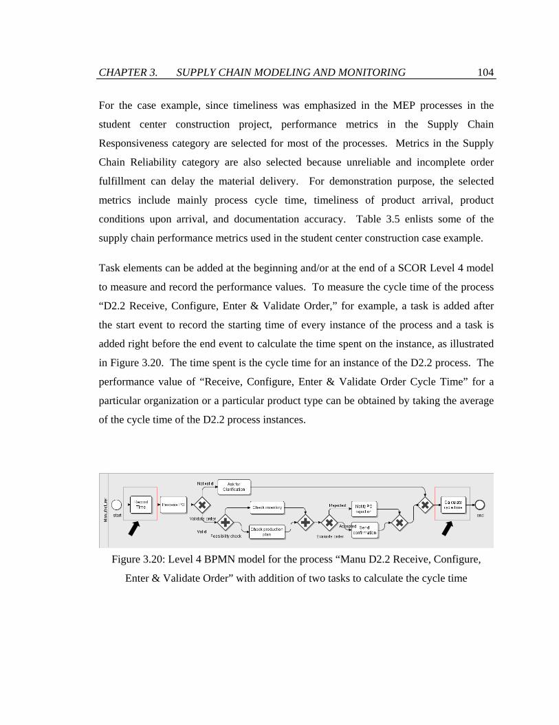
CHAPTER 3. SUPPLY CHAIN MODELING AND MONITORING 104
For the case example, since timeliness was emphasized in the MEP processes in the
student center construction project, performance metrics in the Supply Chain
Responsiveness category are selected for most of the processes. Metrics in the Supply
Chain Reliability category are also selected because unreliable and incomplete order
fulfillment can delay the material delivery. For demonstration purpose, the selected
metrics include mainly process cycle time, timeliness of product arrival, product
conditions upon arrival, and documentation accuracy. Table 3.5 enlists some of the
supply chain performance metrics used in the student center construction case example.
Task elements can be added at the beginning and/or at the end of a SCOR Level 4 model
to measure and record the performance values. To measure the cycle time of the process
“D2.2 Receive, Configure, Enter & Validate Order,” for example, a task is added after
the start event to record the starting time of every instance of the process and a task is
added right before the end event to calculate the time spent on the instance, as illustrated
in Figure 3.20. The time spent is the cycle time for an instance of the D2.2 process. The
performance value of “Receive, Configure, Enter & Validate Order Cycle Time” for a
particular organization or a particular product type can be obtained by taking the average
of the cycle time of the D2.2 process instances.
Figure 3.20: Level 4 BPMN model for the process “Manu D2.2 Receive, Configure,
Enter & Validate Order” with addition of two tasks to calculate the cycle time

CHAPTER 3. SUPPLY CHAIN MODELING AND MONITORING 105
Table 3.5: Examples of supply chain performance metrics used in the case example
SCOR Supply Chain Processes SCOR Performance Metrics P1.4 Establish & Communicate Supply-Chain Plans
• (RS) Establish Supply Chain Plans Cycle Time
P2.4 Establish Sourcing Plans • (RS) Establish Sourcing Plans Cycle Time P3.4 Establish Production Plans • (RS) Establish Production Plans Cycle Time P4.4 Establish Delivery Plans • (RS) Establish Delivery Plans Cycle Time S1.1 S2.1 S3.3 Schedule Product Deliveries
• (RS) Schedule Product Deliveries Cycle Time • (RS) Average Days per Schedule Change • (CO) Quantity per shipment
S1.2 S2.2 S3.4 Receive Product • (RL) % Orders/ Lines Received On-Time • (RL) % Orders/ Lines Received with Correct
Shipping Documents • (RS) Receiving Product Cycle Time
S1.3 S2.3S3.5 Verify Product • (RL) % Orders/ Lines Received Defect Free • (RL) % Orders/ lines Received with Correct
Content • (RS) Verify Product Cycle Time
M1.1 M2.1 Schedule Production Activities
• (RS) Schedule Production Activities Cycle Time
• (AM) Capacity Utilization M2.2 M3.3 Issue Sourced/ In-Process Product
• (RS) Issue Sourced/In-Process Product Cycle Time
• (CO) Quantity per Shipment M2.3 Produce and Test • (RL) Yield
• (RS) Produce and Test Cycle Time • (AM) Capacity Utilization
D1.1 D2.1 Process Inquiry and Quote
• (RS) Process Inquiry & Quote Cycle Time
D1.2 D2.2 Receive, Configure, Enter and Validate Order
• (RS) Receive, Configure, Enter & Validate Order Cycle Time
D1.3 D2.3 Reserve Inventory and Determine Delivery Date
• (RL) % of Orders Delivered In Full • (RS) Reserve Inventory & Determine Delivery
Date Cycle Time D1.8 D2.8 D3.8 Receive Product from Source or Make
• (RL) % correct material documentation • (RS) Receive Product from Source or Make
Cycle Time

CHAPTER 3. SUPPLY CHAIN MODELING AND MONITORING 106
3.4.2 System Implementation
The SCOR Level 3 and Level 4 BPMN models developed in Section 3.3.3 are deployed
in the SC Collaborator system framework. Each of these models is deployed as a
separate process service unit to be integrated in the system. The process service units are
implemented using Business Process Execution Language (BPEL) [80], an
implementation-level standard for web services orchestration. The SCOR Level 3 and
Level 4 BPMN models are converted to BPEL processes, which are deployed in an
orchestration engine for execution. After deployment, a Web Service Description
Language (WSDL) [104] document that describes the deployed BPEL process units is
available for each of the deployed SCOR Level 3 and Level 4 BPEL processes. The
WSDL documents provide information on how to invoke the process units.
Figure 3.21 illustrates the relationship among different components in the SCOR-based
SC Collaborator system framework. There are three types of service units – SCOR Level
3 process units, SCOR Level 4 process units, and fundamental web service units.
• As discussed in Section 3.3.3, SCOR Level 3 models can be categorized for (1)
stocked standard products, (2) make-to-order standard / configurable products,
and (3) custom products. Each role in the Level 3 model is deployed as a BPEL
process unit. Each SCOR Level 3 process node in the Level 3 models links to a
SCOR Level 4 process unit. For example, as represented in Figure 3.21, the
SCOR Level 3 process unit of the Subcontractor role for stocked products links to
the SCOR Level 4 process units of “D2.2” and “P4.4.” WSDL documents of the
Level 4 process units are needed for service invocation.
• The SCOR Level 4 BPEL process units integrate the fundamental web service
units to perform various SCOR Level 3 processes. The process units refer to the
WSDL documents of the fundamental service units for service invocation.

CHAPTER 3. SUPPLY CHAIN MODELING AND MONITORING 107
Fundamental Web Service Units
SCOR Level 4 Process Units
Centralized User InterfaceSC Collaborator Layout
Web services
App 1Wrapper
Application Portlet Unit
Portlet gateway
Web services
App 3Wrapper
Web services
Source 2WrapperWeb services
App 2WrapperWeb services
Source 1Wrapper
BPEL (D2.2) BPEL (P4.4) BPEL (D2.3)
BPEL (Stocked-Subcon) BPEL (MTO-
Manu)BPEL (Custom-
Subcon)
SCOR Level 3 Process Units
Application Portlet Unit
Portlet gateway
Application Portlet Unit
Portlet gateway
Application Portlet Units
WSDL WSDL
WSDLWSDL
WSDL
WSDLWSDLWSDL
WSDLWSDL
WSDL
Figure 3.21: Incorporating SCOR Level 3 and Level 4 models in SC Collaborator
• Fundamental web service units include both the internal and external web service
units that are available to invocation. These web service units may perform
various operations such as offering data or system functionality, running an
application, or modifying information. The implementation and deployment of
web service units in SC Collaborator are discussed in Section 2.4. Each of these
web service units is associated with a WSDL specification document.
Figure 3.22 shows the procedures to implement a SCOR-based SC Collaborator system
framework based on SCOR Level 3 and Level 4 models. First, SCOR Level 4 BPMN
models are converted into BPEL skeleton files, which capture the process flows
described in the BPMN models. The skeleton files form the basis to develop complete,
executable BPEL process files. BPEL deployment packages are then created by
combining the BPEL process files with the WSDL documents that describe the Level 4

CHAPTER 3. SUPPLY CHAIN MODELING AND MONITORING 108
BPEL processes. The deployment packages are then deployed by Apache ODE engine
[9], an open source BPEL execution engine developed by the Apache Software
Foundation. Similarly, SCOR Level 3 BPMN models are converted into BPEL skeleton
files. Referring to the deployed SCOR Level 4 process units, complete Level 3 BPEL
process files are created. After that, deployment packages are built and deployed using
Apache ODE engine. Finally, both the SCOR Level 3 and Level 4 process units can be
invoked by application portlet units in SC Collaborator for system operations and layouts.
The details of the procedures are presented in the following sections.
Figure 3.22: Procedures to incorporate the SCOR models to the service oriented SC
Collaborator system framework
[Level 4] BPMN models
[Level 4] BPEL skeleton files
[Level 4] Complete BPEL process files
Conversion program (Java)
Add details Link to web service units (Eclipse BPEL Visual Designer)
[Level 3] BPMN models
[Level 3] BPEL skeleton files
[Level 3] Complete BPEL process files
Conversion program (Java)
Add details Link to Level 4 BPEL units (Eclipse BPEL Visual Designer)
[Level 4] BPEL Deployment Package
[Level 3] BPEL Deployment Package
[Level 4] Deployed BPEL Processes
Deploy BPEL processes (Apache ODE engine)
[Level 3] Deployed BPEL Processes
Deploy BPEL processes (Apache ODE engine)
Service invocation by Application Portlet Units in
SC Collaborator
WSDL Documents

CHAPTER 3. SUPPLY CHAIN MODELING AND MONITORING 109
3.4.2.1 Conversion of BPMN Models into BPEL Skeleton Files
BPMN models cannot be executed directly due to its high level of abstraction. However,
BPMN models can be easily converted into BPEL [80]. The converted BPEL files
capture the process flow and logic specified in the BPMN models. However, to make the
converted BPEL files executable, specifications of the BPEL activities and the partner
links have to be added.
BPMN models are stored and transferred using XML Metadata Interchange (XMI)
format. XMI is a standard developed by OMG for exchanging metadata information via
Extensible Markup Language (XML). To convert BPMN models into BPEL files, XMI
output of the BPMN models are exported, and then parsed to extract the process
definitions and sequences. Figure 3.23 shows the XMI representation of the BPMN
model for the SCOR Level 3 process “Manu D2.2 Receive, Configure, Enter & Validate
Order,” which is depicted in Figure 3.20. In the XMI output, every event, gateway,
activity, or artifact object is represented as an individual <vertices> element, while every
connecting object is represented as a <sequenceEdges> element. As illustrated in Figure
3.23, an XMI file indicates the linkages between the flow objects (events, gateways and
activities) represented in a BPMN model.
A Java conversion program has been built to parse XMI files and to create a BPEL
skeleton file for every BPMN model. The program instantiates a Java class Process for
every extracted <vertices> element. Every Process instance has (1) a process name, (2)
a process type, and (3) a list of succeeding Process instances. The name attribute of a
<vertices> element is used as the process name. The activityType attribute of a
<vertices> element is converted and used as the process type. The conversions between
activityType attribute values and the BPEL process type are listed in Table 3.6. The
outgoingEdges and incomingEdges attributes of <vertices> elements are matched to each
other to regenerate the sequences and relationships of the flow objects. As illustrated in
Figure 3.23, for example, the outgoingEdges attribute of <vertices> element “start”

CHAPTER 3. SUPPLY CHAIN MODELING AND MONITORING 110
<?xml version="1.0" encoding="UTF-8"?> <bpmn:BpmnDiagram xmi:version="2.0"
xmlns:xmi="http://www.omg.org/XMI" xmlns:bpmn="http://stp.eclipse.org/bpmn" xmi:id="_7eIVwYYMEd6DcYMaJrJywg" iD="_7eIVwIYMEd6DcYMaJrJywg"> <pools xmi:type="bpmn:Pool" xmi:id="_7fUokYYMEd6DcYMaJrJywg"
iD="_7fUokIYMEd6DcYMaJrJywg" name="Manufacturer"> <vertices xmi:type="bpmn:Activity"
xmi:id="_ED9jIYYNEd6DcYMaJrJywg" iD="_ED9jIIYNEd6DcYMaJrJywg" outgoingEdges="_ZJwbsYYOEd6DcYMaJrJywg" name="start" activityType="EventStartEmpty"/>
<vertices xmi:type="bpmn:Activity" xmi:id="_7fUok4YMEd6DcYMaJrJywg" iD="_7fUokoYMEd6DcYMaJrJywg" outgoingEdges="_oin4kYYNEd6DcYMaJrJywg" incomingEdges="_ZJwbsYYOEd6DcYMaJrJywg" name="Record Time" activityType="Task"/>
: <vertices xmi:type="bpmn:Activity"
xmi:id="_Xy4vYYYOEd6DcYMaJrJywg" iD="_Xy4vYIYOEd6DcYMaJrJywg" incomingEdges="_Xy4vaoYOEd6DcYMaJrJywg" name="end" activityType="EventEndEmpty"/>
<sequenceEdges xmi:type="bpmn:SequenceEdge" xmi:id="_ZJwbsYYOEd6DcYMaJrJywg" iD="_ZJwbsIYOEd6DcYMaJrJywg" source="_ED9jIYYNEd6DcYMaJrJywg" target="_7fUok4YMEd6DcYMaJrJywg"/>
<sequenceEdges xmi:type="bpmn:SequenceEdge" xmi:id="_oin4kYYNEd6DcYMaJrJywg" iD="_oin4kIYNEd6DcYMaJrJywg" source="_7fUok4YMEd6DcYMaJrJywg" target="_oiUWkYYNEd6DcYMaJrJywg"/>
: <sequenceEdges xmi:type="bpmn:SequenceEdge"
xmi:id="_r2D_QYYNEd6DcYMaJrJywg" iD="_r2D_QIYNEd6DcYMaJrJywg" name="Not validated" source="_oiUWkYYNEd6DcYMaJrJywg" target="_r16OQYYNEd6DcYMaJrJywg"/>
</pools> </bpmn:BpmnDiagram>
Figure 3.23: XMI representation of the SCOR Level 4 BPMN model for the process
“Manu D2.2 Receive, Configure, Enter & Validate Order,” which is shown in Figure 3.20
matches the incomingEdges attribute of the succeeding <vertices> element “Process PO.”
The unique IDs of these two elements are specified in the <sequenceEdges> element
linking the <vertices> elements. As an example, the Process class instance for the
<vertices> element highlighted in Figure 3.23 has a value of (process name = “start”,
process type = “empty”, succeeding = [“Process@19821f”]), where “Process@19821f” is
the internal ID for the Process class instance with process name “Process PO.”
Vertex ID
Vertex ID
Vertex IDs
Edge ID
Edge ID
Edge ID

CHAPTER 3. SUPPLY CHAIN MODELING AND MONITORING 111
Table 3.6: Conversion table from BPMN elements to BPEL elements
BPMN element type “activityType” attribute value Converted BPEL activity Event EventStartEmpty <bpel:empty> Event EventEndEmpty <bpel:empty>
Activity Task, or null <bpel:empty>
Gateway GatewayDataBasedExclusive <bpel:if>, <bpel:elseif>, <bpel:else>
Gateway GatewayDataBasedInclusive <bpel:if> Gateway GatewayParallel <bpel:flow>
After parsing all the <vertices> elements in an XMI file, the Java conversion program
generates a linked list of instances of the class Process internally. The linked list is
then converted into a BPEL skeleton file with the corresponding BPEL activity tags. The
internally generated linked list and the BPEL skeleton file of the SCOR Level 4 model
for “Manu D2.2 Receive, Configure, Enter & Validate Order” are shown in Figure 3.24
and Figure 3.25, respectively. As illustrated in Figure 3.25, whenever there is an “if”
process instance or a “flow” process instance, the elements in the resulted BPEL skeleton
will move a level down. The conversion program finally adds an <bpel:process> tag as
the beginning element of the XML-based BPEL skeleton file.
SCOR Level 3 BPMN models can also be converted to BPEL skeleton files using the
conversion program using the same approach. Each lane in the SCOR Level 3 BPMN
model generates a single BPEL skeleton file. Figure 3.26 shows the BPEL skeleton file
for the “Subcontractor” lane in the SCOR Level 3 model for stocked standard products,
which is shown in Figure 3.14.

CHAPTER 3. SUPPLY CHAIN MODELING AND MONITORING 112
Figure 3.24: The linked list of “Process” class instances after parsing the SCOR Level 4
model for the process “Manu D2.2 Receive, Configure, Enter & Validate Order”
<?xml version="1.0" encoding="UTF-8"?> <bpel:process exitOnStandardFault="yes" name="Manu D2.2“
suppressJoinFailure="yes” xmlns:bpel="http://docs.oasis-open.org/wsbpel/2.0/process/executable">
<bpel:sequence> <bpel:empty name="start"/> <bpel:empty name="Record Time"/> <bpel:empty name="Process PO"/> <bpel:if name="Validate order"> <bpel:sequence> <bpel:flow name="Feasibility check"> <bpel:empty name="Check inventory"/> <bpel:empty name="Check production plan"/> </bpel:flow> <bpel:if name="Evaluate order"> <bpel:empty name="Notify PO rejection"/> <bpel:elseif> <bpel:empty name="Send confirmation"/> </bpel:elseif> </bpel:if> </bpel:sequence> <bpel:elseif> <bpel:empty name="Ask for Clarification"/> </bpel:elseif> </bpel:if> <bpel:empty name="Calculate cycle time"/> <bpel:empty name="end"/> </bpel:sequence> </bpel:process>
Figure 3.25: BPEL skeleton file converted from the linked list of “Process” class
instances depicted in Figure 3.24
start [Empty]
Process PO[Empty]
Validate order [If]
Ask for Clarification
[Empty]
Check inventory [Empty]
Feasibility check [Flow]
Check production
plan [Empty]
[Flow]
Evaluate order [If]
Notify PO rejection [Empty]
Send confirmation
[Empty]
[If]
[If]
end [Empty]
Type
Name
Process class
instance
Record Time
[Empty]
Calculate cycle time [Empty]

CHAPTER 3. SUPPLY CHAIN MODELING AND MONITORING 113
<?xml version="1.0" encoding="UTF-8"?> <bpel:process exitOnStandardFault="yes" name="Stocked-Subcontractor"
suppressJoinFailure="yes" xmlns:bpel="http://docs.oasis-open.org/wsbpel/2.0/process/executable">
<bpel:sequence> <bpel:empty name="start"/> <bpel:empty name="Sub P1.4 Est. SC Plans"/> <bpel:empty name="Sub P2.4 Est. Sourcing Plans"/> <bpel:empty name="Sub S1.1 Schedule Prod. Deliveries"/> <bpel:if name="Deliver Warehouse">
<bpel:sequence> <bpel:empty name="Sub S1.2 Receive Product"/> <bpel:empty name="Sub S1.3 Verify Product"/> <bpel:empty name="Sub S1.4 Transfer Product"/> <bpel:flow name="Inventory"> <bpel:empty name="Sub P4.4 Est. Delivery Plans"/> <bpel:empty/> </bpel:flow> <bpel:empty name="Sub D1.8 Receive Prod. from S/M"/> <bpel:empty name="Sub D1.11 Load Product"/> <bpel:empty name="Sub D1.12 Ship Product"/> </bpel:sequence> </bpel:if> <bpel:empty name="Sub S1.2 Receive Product"/> <bpel:empty name="Sub S1.3 Verify Product"/> <bpel:empty name="end"/> </bpel:sequence> </bpel:process>
Figure 3.26: BPEL skeleton file converted from the “Subcontractor” lane in the SCOR
Level 3 BPMN model for stocked standard products, which is shown in Figure 3.14
3.4.2.2 Completing BPEL Process Files
The generated BPMN skeleton file only describes the process flow represented in BPMN
model. The process flow serves as a backbone for the orchestration logic section of a
BPEL process file. Detailed specification of the BPEL activities and the PartnerLinks
and Variables sections need to be added before the BPEL process can be deployed.
Eclipse BPEL Visual Designer [32], an open source BPEL editor developed by the
Eclipse Foundation, is used to facilitate the addition of implementation and connection
details to BPEL skeleton files.

CHAPTER 3. SUPPLY CHAIN MODELING AND MONITORING 114
To obtain a complete SCOR Level 4 BPEL process file, a new BPEL process file is
created in Eclipse BPEL Visual Designer. The BPEL codes in the generated Level 4
skeleton file are then copied to the new empty BPEL process file. Specifications of the
BPEL activities, partner links, and variables are then defined using the user interface
provided in Eclipse BPEL Visual Designer. Creation of a new BPEL process file in
Eclipse BPEL Visual Designer generates a WSDL document that is linked to the BPEL
process file. The WSDL document is modified automatically by the BPEL editor
whenever the linked BPEL process file is changed. Therefore, consistency between the
WSDL and BPEL files can be guaranteed.
Consider the SCOR Level 4 model for the process “Manu D2.2 Receive, Configure,
Enter & Validate Order” as an example. Figure 3.27 shows the Eclipse BPEL Visual
Designer displaying a new BPEL file with the BPEL codes from the skeleton file, which
are shown in Figure 3.25. When a BPEL activity is selected in the display in the BPEL
editor, the Properties window shows a form for entering specification details of the
selected BPEL activity. The form is dependent on the type of the selected BPEL
activities. For instance, when the empty BPEL activity “Check inventory” is selected, the
Properties window shows an option to replace the empty activity by a invoke, receive,
reply, or assign activity, as illustrated in Figure 3.27.

CHAPTER 3. SUPPLY CHAIN MODELING AND MONITORING 115
Figure 3.27: Eclipse BPEL Visual Designer for completing the BPEL process file
For receive, reply and invoke activities, the partnerLink, portType, operation, and
variable attributes should be defined. Take the activity “Check inventory” as an
example. It is replaced by an invoke BPEL activity using the interface in Eclipse BPEL
Visual Designer. As illustrated in Figure 3.28, when the replaced “Check inventory”
activity is selected, the Properties window allows creation of a partner link that will be
associated with the activity. After naming the newly created partner link as “Inventory,”
WSDL document of the service unit Inventory Service is then imported to the BPEL
editor. The editor can extract the specification from the imported WSDL file such as the
service port type and the data structure of the request and response messages. Users can
Invoke
Receive
Reply Assign
Empty
Properties window

CHAPTER 3. SUPPLY CHAIN MODELING AND MONITORING 116
associate the service unit Inventory Service to the newly created partner link “Inventory”
and assign the partner link to the activity “Check inventory,” as demonstrated in Figure
3.28. Finally, the operation “checkInventory” of the service unit Inventory Service is
selected. This automatically generates the variables with data structure consistent to the
request and response messages of the operation “checkInventory,” and assigns the
variables as well as the operation to the BPEL activity “Check inventory.” The BPEL
codes added at the back-end are shown in Figure 3.29.
Figure 3.28: Creating and assigning partner link to an invoke activity “Check inventory”
Create and assign partner link to invoke activity “Check inventory”
Definition of input and output message structures of operation “checkInventory” from WSDL document
From WSDL of service unit “Inventory Service”

CHAPTER 3. SUPPLY CHAIN MODELING AND MONITORING 117
: <bpel:partnerLink name="Inventory" partnerLinkType="tns:InventoryPLT"
partnerRole="ServiceProvider" /> : <bpel:variable name="InventoryResponse"
messageType="ns:checkInventoryResponse" /> <bpel:variable name="InventoryRequest"
messageType="ns:checkInventoryRequest" /> : <bpel:invoke name="Check inventory" partnerLink="Inventory"
operation="checkInventory" portType="ns:InventoryServicePortType" inputVariable="InventoryRequest" outputVariable="InventoryResponse" />
:
Figure 3.29: Specification details for the “Check inventory” activity added to the BPEL
process file
Eclipse BPEL Visual Designer also allows a user-friendly interface for checking,
modifying and managing the specification details of each component in a BPEL process
file. As illustrated in Figure 3.30, for example, the created partner link “Inventory” and
variables “InventoryResponse” and “InventoryRequest” are listed in the user interface
display. When the partner link is selected, the Properties window shows the partner role
and available service operations of the service unit associated with the partner link.
Similarly, the definition of partner link, operation, input variable, and output variable for
the activity “Check inventory” can be conveniently viewed and changed using the
Properties window in the user interface, as shown in Figure 3.31.

CHAPTER 3. SUPPLY CHAIN MODELING AND MONITORING 118
Figure 3.30: Displaying the definition of the partner link “Inventory”
Figure 3.31: Displaying the specification of the BPEL activity “Check inventory”
Partner link named “Inventory” is defined
Available service operations
Partner role
Variables that are consistent with the request and response messages of “checkInventory” are automatically created
Operation “checkInventory”
Definition of BPEL activity “Check inventory”
Partner link
Operation
Variables

CHAPTER 3. SUPPLY CHAIN MODELING AND MONITORING 119
Based on the BPEL codes from BPEL skeleton files, specification details of the activities,
partner links and variables can be added easily using the BPEL editor Eclipse BPEL
Visual Designer. As the BPEL process files are changed, the BPEL editor also modifies
the WSDL documents associated with them, which are useful for deployment and
invocation of the BPEL service units. The complete BPEL process file and the
associated WSDL document of the Level 4 model for the process “Manu D2.2 Receive,
Configure, Enter & Validate Order” are shown in Figure 3.32 and Figure 3.33,
respectively.
For SCOR Level 3 models, similar procedures are taken to build complete, executable
BPEL process files from BPEL skeleton files, which are converted from Level 3 BPMN
models. The only difference is that SCOR Level 3 BPEL processes integrate multiple
Level 4 processes while SCOR Level 4 BPEL processes integrate multiple fundamental
service units. Therefore, WSDL documents of various Level 4 BPEL process units are
imported when adding specification details to SCOR Level 3 BPEL processes using
Eclipse BPEL Visual Designer. The complete BPEL process file and the associate
WSDL document of the “Subcontractor” role in the Level 3 model for stocked standard
products are illustrated in Figure 3.34 and Figure 3.35, respectively.

CHAPTER 3. SUPPLY CHAIN MODELING AND MONITORING 120
<bpel:process name="Manu_D2_2" suppressJoinFailure="yes" targetNamespace="http://localhost:8080/service/process/Manu_D2_2" xmlns:bpel="http://docs.oasis-open.org/wsbpel/2.0/process/executable"> <bpel:import location="Manu_D2_2Artifacts.wsdl" namespace="http://localhost:8080/service/process/Manu_D2_2" importType="http://schemas.xmlsoap.org/wsdl/" /> <bpel:partnerLinks> <bpel:partnerLink name="client" partnerLinkType="tns:Manu_D2_2" myRole="Manu_D2_2Provider" partnerRole="Manu_D2_2Requester" /> <bpel:partnerLink name="Inventory" partnerLinkType="tns:InventoryPLT" partnerRole="ServiceProvider"></bpel:partnerLink> : <bpel:partnerLink name="Message" partnerLinkType="tns:MessagePLT" partnerRole="ServiceProvider"></bpel:partnerLink> </bpel:partnerLinks> <bpel:variables> <bpel:variable name="input" messageType="tns:Manu_D2_2RequestMessage"/> <bpel:variable name="output" messageType="tns:Manu_D2_2ResponseMessage"/> <bpel:variable name="InventoryResponse" messageType="ns:checkInventoryResponse" /> <bpel:variable name="InventoryRequest" messageType="ns:checkInventoryRequest" /> : <bpel:variable name="MessageRequest" messageType="ns:addMessageRequest" /> <bpel:variable name="CycleTimeRequest1" messageType="ns:calculateCycleTimeRequest" /> </bpel:variables> <bpel:sequence name="main"> <bpel:receive name="start" partnerLink="client" portType="tns:Manu_D2_2" operation="initiate" variable="input" createInstance="yes"/> <bpel:invoke name="Record Time" partnerLink="CycleTime" operation="addCycleTime" portType="ns:CycleTimeServicePortType" inputVariable="CycleTimeRequest" /> <bpel:invoke name="Process PO" partnerLink="MaterialOrder" operation="processOrder" portType="ns:MaterialOrderServicePortType" inputVariable="MaterialOrderRequest" outputVariable="MaterialOrderResponse" /> <bpel:if name="Validate order"> <bpel:condition><![CDATA[$input.payload/tns:orderNumber!="" && $$input.payload/tns:productCode!="" && $$input.payload/tns:quantity>0 && $$input.payload/tns:fromCompany!=""]]></bpel:condition> <bpel:sequence> <bpel:flow name="Feasibility check"> <bpel:invoke name="Check inventory" partnerLink="Inventory" operation="checkInventory" portType="ns:InventoryServicePortType" inputVariable="InventoryRequest" outputVariable="InventoryResponse" /> <bpel:invoke name="Check production plan" partnerLink="Production" operation="checkProductionPlan" portType="ns0:production" inputVariable="ProductionRequest" outputVariable="ProductionResponse" /> </bpel:flow> <bpel:if name="Evaluate order"> <bpel:condition>...</bpel:condition> <bpel:invoke name="Notify PO rejection" partnerLink="Message" operation="addMessage" portType="ns:MessageServicePortType" inputVariable="MessageRequest" /> <bpel:elseif> <bpel:invoke name="Send confirmation" partnerLink="Message" operation="addMessage" portType="ns:MessageServicePortType" inputVariable="MessageRequest" /> </bpel:elseif> </bpel:if> </bpel:sequence> <bpel:elseif> <bpel:invoke name="Ask for Clarification" partnerLink="Message" operation="addMessage" inputVariable="MessageRequest" /> </bpel:elseif> </bpel:if> <bpel:invoke name="Calculate cycle time" partnerLink="CycleTime" operation="calculateCycleTime" portType="ns:CycleTimeServicePortType" inputVariable="CycleTimeRequest1" /> </bpel:sequence> </bpel:process>
Figure 3.32: Excerpt of the complete BPEL process file of the Level 4 model for the
process “Manu D2.2 Receive, Configure, Enter & Validate Order”
Import
Partner links
Variables
Orchestration logic
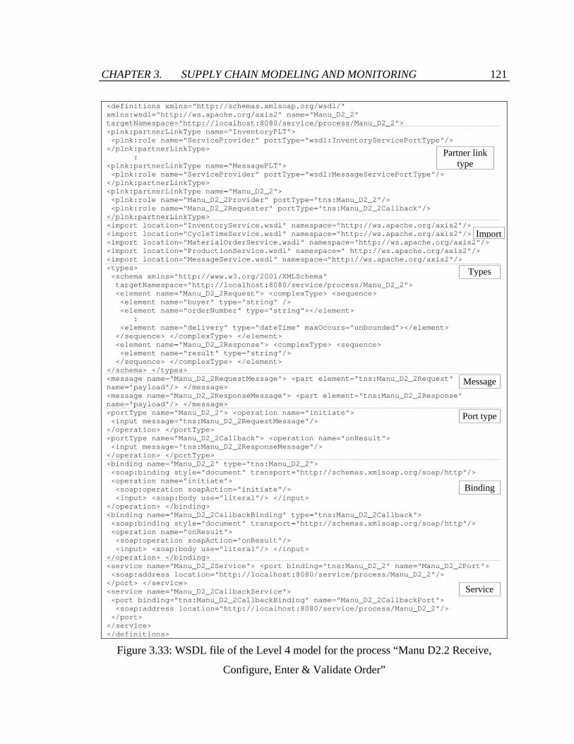
CHAPTER 3. SUPPLY CHAIN MODELING AND MONITORING 121
<definitions xmlns="http://schemas.xmlsoap.org/wsdl/" xmlns:wsdl="http://ws.apache.org/axis2" name="Manu_D2_2" targetNamespace="http://localhost:8080/service/process/Manu_D2_2"> <plnk:partnerLinkType name="InventoryPLT"> <plnk:role name="ServiceProvider" portType="wsdl:InventoryServicePortType"/> </plnk:partnerLinkType> : <plnk:partnerLinkType name="MessagePLT"> <plnk:role name="ServiceProvider" portType="wsdl:MessageServicePortType"/> </plnk:partnerLinkType> <plnk:partnerLinkType name="Manu_D2_2"> <plnk:role name="Manu_D2_2Provider" portType="tns:Manu_D2_2"/> <plnk:role name="Manu_D2_2Requester" portType="tns:Manu_D2_2Callback"/> </plnk:partnerLinkType> <import location="InventoryService.wsdl" namespace="http://ws.apache.org/axis2"/> <import location="CycleTimeService.wsdl" namespace="http://ws.apache.org/axis2"/> <import location="MaterialOrderService.wsdl" namespace="http://ws.apache.org/axis2"/> <import location="ProductionService.wsdl" namespace=" http://ws.apache.org/axis2"/> <import location="MessageService.wsdl" namespace="http://ws.apache.org/axis2"/> <types> <schema xmlns="http://www.w3.org/2001/XMLSchema" targetNamespace="http://localhost:8080/service/process/Manu_D2_2"> <element name="Manu_D2_2Request"> <complexType> <sequence> <element name="buyer" type="string" /> <element name="orderNumber" type="string"></element> : <element name="delivery" type="dateTime" maxOccurs="unbounded"></element> </sequence> </complexType> </element> <element name="Manu_D2_2Response"> <complexType> <sequence> <element name="result" type="string"/> </sequence> </complexType> </element> </schema> </types> <message name="Manu_D2_2RequestMessage"> <part element="tns:Manu_D2_2Request" name="payload"/> </message> <message name="Manu_D2_2ResponseMessage"> <part element="tns:Manu_D2_2Response" name="payload"/> </message> <portType name="Manu_D2_2"> <operation name="initiate"> <input message="tns:Manu_D2_2RequestMessage"/> </operation> </portType> <portType name="Manu_D2_2Callback"> <operation name="onResult"> <input message="tns:Manu_D2_2ResponseMessage"/> </operation> </portType> <binding name="Manu_D2_2" type="tns:Manu_D2_2"> <soap:binding style="document" transport="http://schemas.xmlsoap.org/soap/http"/> <operation name="initiate"> <soap:operation soapAction="initiate"/> <input> <soap:body use="literal"/> </input> </operation> </binding> <binding name="Manu_D2_2CallbackBinding" type="tns:Manu_D2_2Callback"> <soap:binding style="document" transport="http://schemas.xmlsoap.org/soap/http"/> <operation name="onResult"> <soap:operation soapAction="onResult"/> <input> <soap:body use="literal"/> </input> </operation> </binding> <service name="Manu_D2_2Service"> <port binding="tns:Manu_D2_2" name="Manu_D2_2Port"> <soap:address location="http://localhost:8080/service/process/Manu_D2_2"/> </port> </service> <service name="Manu_D2_2CallbackService"> <port binding="tns:Manu_D2_2CallbackBinding" name="Manu_D2_2CallbackPort"> <soap:address location="http://localhost:8080/service/process/Manu_D2_2"/> </port> </service> </definitions>
Figure 3.33: WSDL file of the Level 4 model for the process “Manu D2.2 Receive,
Configure, Enter & Validate Order”
Partner link type
Import
Types
Message
Port type
Binding
Service

CHAPTER 3. SUPPLY CHAIN MODELING AND MONITORING 122
<bpel:process name="Stocked_Subcon" targetNamespace="http://localhost:8080/service/process/Stocked_Subcon" xmlns:bpel="http://docs.oasis-open.org/wsbpel/2.0/process/executable"> <bpel:import namespace="http://localhost:8080/service/process/Sub_S1_4" location="Sub_S1_4.wsdl" importType="http://schemas.xmlsoap.org/wsdl/"></bpel:import> : <bpel:import namespace="http://localhost:8080/service/process/Sub_P1_4" location="Sub_P1_4.wsdl" importType="http://schemas.xmlsoap.org/wsdl/"></bpel:import> <bpel:import location="Stocked_SubconArtifacts.wsdl" importType="http://schemas.xmlsoap.org/wsdl/" /> <bpel:partnerLinks> <bpel:partnerLink name="client" partnerLinkType="tns:Stocked_Subcon" myRole="Stocked_SubconProvider" partnerRole="Stocked_SubconRequester" /> <bpel:partnerLink name="Sub_P1_4" partnerLinkType="tns:Sub_P1_4PLT" partnerRole="ServiceRequester"></bpel:partnerLink> : <bpel:partnerLink name="Sub_D1_12" partnerLinkType="tns:Sub_D1_12PLT" partnerRole="ServiceRequester"></bpel:partnerLink> </bpel:partnerLinks> <bpel:variables> <bpel:variable name="input" messageType="tns:Stocked_SubconRequestMessage"/> <bpel:variable name="output" messageType="tns:Stocked_SubconResponseMessage"/> <bpel:variable name="Sub_P1_4Request" messageType="ns1:Sub_P1_4ResponseMessage" /> : <bpel:variable name="Sub_D1_12Request" messageType="ns8:Sub_D1_12ResponseMessage" /> </bpel:variables> <bpel:sequence name="main"> <bpel:receive name="receiveInput" partnerLink="client" portType="tns:Stocked_Subcon" operation="initiate" variable="input" createInstance="yes"/> <bpel:invoke name="Sub P1.4 Est. SC Plans" partnerLink="Sub_P1_4" operation="onResult" portType="ns1:Sub_P1_4Callback" inputVariable="Sub_P1_4Request"/> <bpel:invoke name="Sub P2.4 Est. Sourcing Plans" partnerLink="Sub_P2_4" operation="onResult" portType="ns2:Sub_P2_4Callback" inputVariable="Sub_P2_4Request"/> <bpel:invoke name="Sub S1.1 Schedule Prod. Deliveries" partnerLink="Sub_S1_1" operation="onResult" portType="ns3:Sub_S1_1Callback" inputVariable="Sub_S1_1Request"/> <bpel:if name="Deliver Warehouse"> <bpel:sequence> <bpel:invoke name="Sub S1.2 Receive Product" partnerLink="Sub_S1_2" operation="onResult" portType="ns4:Sub_S1_2Callback" inputVariable="Sub_S1_2Request"/> <bpel:invoke name="Sub S1.3 Verify Product" partnerLink="Sub_S1_3" operation="onResult" portType="ns5:Sub_S1_3Callback" inputVariable="Sub_S1_3Request"/> <bpel:invoke name="Sub S1.4 Transfer Product" partnerLink="Sub_S1_4" operation="onResult" portType="ns6:Sub_S1_4Callback" inputVariable="Sub_S1_4Request"/> <bpel:invoke name="Sub P4.4 Est. Delivery Plans" partnerLink="Sub_P4_4"/> <bpel:invoke name="Sub D1.8 Receive Prod. from S/M" partnerLink="Sub_D1_8" operation="onResult" portType="ns0:Sub_D1_8Callback" inputVariable="Sub_D1_8Request"/> <bpel:invoke name="Sub D1.11 Load Product" partnerLink="Sub_D1_11" operation="onResult" portType="ns7:Sub_D1_11Callback" inputVariable="Sub_D1_11Request"/> <bpel:invoke name="Sub D1.12 Ship Product" partnerLink="Sub_D1_12" operation="onResult" portType="ns8:Sub_D1_12Callback" inputVariable="Sub_D1_12Request"/> </bpel:sequence> </bpel:if> <bpel:invoke name="Sub S1.2 Receive Product" partnerLink="Sub_S1_2" operation="onResult" inputVariable="Sub_S1_2Request"/> <bpel:invoke name="Sub S1.3 Verify Product" partnerLink="Sub_S1_3" operation="onResult" inputVariable="Sub_S1_3Request"/> <bpel:invoke name="callbackClient" partnerLink="client" portType="tns:Stocked_SubconCallback" operation="onResult" inputVariable="output"/> </bpel:sequence> </bpel:process>
Figure 3.34: Excerpt of the complete BPEL process file of the “Subcontractor” role in the
Level 3 model for stocked standard products
Import
Partner links
Variables
Orchestration logic

CHAPTER 3. SUPPLY CHAIN MODELING AND MONITORING 123
<definitions xmlns="http://schemas.xmlsoap.org/wsdl/" xmlns:soap="http://schemas.xmlsoap.org/wsdl/soap/" name="Stocked_Subcon" targetNamespace="http://localhost:8080/service/process/Stocked_Subcon"> <plnk:partnerLinkType name="Sub_P1_4PLT"> <plnk:role name="ServiceProvider" portType="wsdl:Sub_P1_4"/> <plnk:role name="ServiceRequester" portType="wsdl:Sub_P1_4Callback"/> </plnk:partnerLinkType> : <plnk:partnerLinkType name="Sub_D1_12PLT"> <plnk:role name="ServiceProvider" portType="wsdl8:Sub_D1_12"/> <plnk:role name="ServiceRequester" portType="wsdl8:Sub_D1_12Callback"/> </plnk:partnerLinkType> <plnk:partnerLinkType name="Stocked_Subcon"> <plnk:role name="Stocked_SubconProvider" portType="tns:Stocked_Subcon"/> <plnk:role name="Stocked_SubconRequester" portType="tns:Stocked_SubconCallback"/> </plnk:partnerLinkType> <import location="Sub_P1_4.wsdl" namespace="http://localhost:8080/service/process/Sub_P1_4"/> <import location="Sub_D1_12.wsdl" namespace="http://localhost:8080/service/process/Sub_D1_12"/> <types> <schema xmlns="http://www.w3.org/2001/XMLSchema" attributeFormDefault="unqualified" targetNamespace="http://localhost:8080/service/process/Stocked_Subcon"> <element name="Stocked_SubconRequest"> <complexType> <sequence> <element name="input" type="string"/> </sequence> </complexType> </element> <element name="Stocked_SubconResponse"> <complexType> <sequence> <element name="result" type="string"/> </sequence> </complexType> </element> </schema> </types> <message name="Stocked_SubconRequestMessage"> <part element="tns:Stocked_SubconRequest" name="payload"/> </message> <message name="Stocked_SubconResponseMessage"> <part element="tns:Stocked_SubconResponse" name="payload"/> </message> <portType name="Stocked_Subcon"> <operation name="initiate"> <input message="tns:Stocked_SubconRequestMessage"/> </operation> </portType> <portType name="Stocked_SubconCallback"> <operation name="onResult"> <input message="tns:Stocked_SubconResponseMessage"/> </operation> </portType> <binding name="Stocked_SubconBinding" type="tns:Stocked_Subcon"> <soap:binding style="document" transport="http://schemas.xmlsoap.org/soap/http"/> <operation name="initiate"> <soap:operation soapAction="initiate"/> <input> <soap:body use="literal"/> </input> </operation> </binding> <binding name="Stocked_SubconCallbackBinding" type="tns:Stocked_SubconCallback"> <soap:binding style="document" transport="http://schemas.xmlsoap.org/soap/http"/> <operation name="onResult"> <soap:operation soapAction=" onResult"/> <input> <soap:body use="literal"/> </input> </operation> </binding> <service name="Stocked_SubconService"> <port binding="tns:Stocked_SubconBinding" name="Stocked_SubconPort"> <soap:address location="http://localhost:8080/service/process/Stocked_Subcon"/> </port> </service> <service name="Stocked_SubconCallbackService"> <port binding="tns:Stocked_SubconCallbackBinding" name="Stocked_SubconCallbackPort"> <soap:address location="http://localhost:8080/service/process/Stocked_SubconCallback"/> </port> </service> </definitions>
Figure 3.35: WSDL file of the “Subcontractor” role in the Level 3 model for stocked
standard products
Partner link type
Import
Types
Message
Port type
Binding
Service

CHAPTER 3. SUPPLY CHAIN MODELING AND MONITORING 124
3.4.2.3 Deployment of BPEL Process Files
The SCOR Level 3 and Level 4 BPEL processes are deployed as web service units in SC
Collaborator for invocation and integration. Deployment of BPEL processes in SC
Collaborator has been discussed in Section 2.4.3.3. To deploy a BPEL process, a
deployment package is created and then submitted to Apache Orchestration Director
Engine (ODE) engine [9] residing in SC Collaborator. A deployment package contains
four components – (1) the BPEL process file to be deployed, (2) a deployment descriptor
with file name “deploy.xml,” (3) a WSDL document that describes the BPEL process to
be deployed, and (4) WSDL documents of the service units invoked in the BPEL process.
As an example, the BPEL deployment package of the “Subcontractor” role in the SCOR
Level 3 model for stocked standard products contains:
• The SCOR Level 3 BPEL process file, as illustrated in Figure 3.34,
• A deployment descriptor file, as illustrated in Figure 3.36,
• The WSDL document associated with the Level 3 BPEL process file, as
illustrated in Figure 3.35, and
• WSDL documents of the SCOR Level 4 process units invoked in the Level 3
BPEL process, such as “Sub P1.4”, “Sub P2.4” and “Sub D1.12.” The WSDL
documents are similar to the WSDL document of the process unit “Manu D2.2,”
which is illustrated in Figure 3.33.
The BPEL deployment package of the SCOR Level 4 model for the Level 3 process
“Manu D2.2 Receive, Configure, Enter & Validate Order” contains:
• The SCOR Level 4 BPEL process file, as illustrated in Figure 3.32,
• A deployment descriptor file, as illustrated in Figure 3.37,

CHAPTER 3. SUPPLY CHAIN MODELING AND MONITORING 125
• The WSDL document associated with the Level 4 BPEL process file, as
illustrated in Figure 3.33, and
• WSDL documents of the fundamental service units invoked in the Level 4 BPEL
process.
<deploy xmlns="http://www.apache.org/ode/schemas/dd/2007/03" xmlns:Stocked_Subcon="http://localhost:8080/service/process/Stocked_Subcon" xmlns:Sub_D1_11="http://localhost:8080/service/process/Sub_D1_11" : xmlns:Sub_S1_4="http://localhost:8080/service/process/Sub_S1_4"> <process name="Stocked_Subcon:Stocked_Subcon"> <active>true</active> <process-events generate="all"/> <provide partnerLink="client"> <service name="Stocked_Subcon:Stocked_SubconService" port="Stocked_SubconPort"/> </provide> <invoke partnerLink="client"> <service name="Stocked_Subcon:Stocked_SubconCallbackService" port="Stocked_SubconCallbackPort"/> </invoke> <invoke partnerLink="Sub_P1_4"> <service name="Sub_S1_4:Sub_S1_4Service" port="Sub_S1_4Port"/> </invoke> <invoke partnerLink="Sub_P2_4"> <service name="Sub_P2_4:Sub_P2_4Service" port="Sub_P2_4Port"/> </invoke> <invoke partnerLink="Sub_P4_4"> <service name="Sub_P4_4:Sub_P4_4Service" port="Sub_P4_4Port"/> </invoke> <invoke partnerLink="Sub_S1_1"> <service name="Sub_S1_1:Sub_S1_1Service" port="Sub_S1_1Port"/> </invoke> <invoke partnerLink="Sub_S1_2"> <service name="Sub_S1_2:Sub_S1_2Service" port="Sub_S1_2Port"/> </invoke> <invoke partnerLink="Sub_S1_3"> <service name="Sub_S1_3:Sub_S1_3Service" port="Sub_S1_3Port"/> </invoke> <invoke partnerLink="Sub_S1_4"> <service name="Sub_S1_4:Sub_S1_4Service" port="Sub_S1_4Port"/> </invoke> <invoke partnerLink="Sub_D1_8"> <service name="Sub_D1_8:Sub_D1_8Service" port="Sub_D1_8Port"/> </invoke> <invoke partnerLink="Sub_D1_11"> <service name="Sub_D1_11:Sub_D1_11Service" port="Sub_D1_11Port"/> </invoke> <invoke partnerLink="Sub_D1_12"> <service name="Sub_D1_12:Sub_D1_12Service" port="Sub_D1_12Port"/> </invoke> </process> </deploy>
Figure 3.36: Deployment descriptor of the “Subcontractor” role in the Level 3 model for
stocked standard products

CHAPTER 3. SUPPLY CHAIN MODELING AND MONITORING 126
<deploy xmlns="http://www.apache.org/ode/schemas/dd/2007/03" xmlns:Manu_D2_2="http://localhost:8080/service/process/Manu_D2_2" xmlns:axis2="http://ws.apache.org/axis2"> <process name="Manu_D2_2:Manu_D2_2"> <active>true</active> <process-events generate="all"/> <provide partnerLink="client"> <service name="Manu_D2_2:Manu_D2_2Service" port="Manu_D2_2Port"/> </provide> <invoke partnerLink="client"> <service name="Manu_D2_2:Manu_D2_2CallbackService" port="Manu_D2_2CallbackPort"/> </invoke> <invoke partnerLink="Inventory"> <service name="axis2:InventoryService" port="InventoryServiceSOAP11port_http"/> </invoke> <invoke partnerLink="CycleTime"> <service name="axis2:CycleTimeService" port="CycleTimeServiceSOAP11port_http"/> </invoke> <invoke partnerLink="MaterialOrder"> <service name="axis2:MaterialOrderService" port="MaterialOrderServiceSOAP11port_http"/> </invoke> <invoke partnerLink="Production"> <service name="production:production" port="productionSOAP"/> </invoke> <invoke partnerLink="Message"> <service name="axis2:MessageService" port="MessageServiceSOAP11port_http"/> </invoke> </process> </deploy>
Figure 3.37: Deployment descriptor of the Level 4 model for the process “Manu D2.2
Receive, Configure, Enter & Validate Order”
3.5 Scenario Demonstration
This section demonstrates the construction supply chain performance measurement
system that is developed for the student center construction project using the system
development framework presented in Section 3.4. The framework leverages the SCOR
models developed in Section 3.3. The scenario is based on the data set obtained from the
construction project, but the names of the companies are modified for privacy and
proprietary reasons. The first step of the system application is company registration. The
submittals from the subcontractors provide the general contractor with information about
the suppliers of every product. At the beginning of the system application, the general
contractor added the names of the distributors and manufacturers for each subcontractor
using an online form in the system (Figure 3.38). Modification and removal of the names

CHAPTER 3. SUPPLY CHAIN MODELING AND MONITORING 127
are also allowed through the online form. The subcontractors then initiated the SCOR
process for any product when they started procurement according to their schedules.
Figure 3.38: General contractor registering the distributors and manufacturers

CHAPTER 3. SUPPLY CHAIN MODELING AND MONITORING 128
The system offers a product-based tracking of the supply chain status at the SCOR Level
3. The start time and finish time for each invocation of SCOR Level 3 processes were
recorded in the system. The general contractor and subcontractors can log in the system
and check the current status of any products they have procured (Figure 3.39). Execution
history of the SCOR Level 3 processes is recorded and stored in the back-end database
for each product. In addition, contractors can also share the SCOR status records with
the members along their supply chains as well as other project participants. For instance,
the electrical subcontractor has shared its information of the electrical components to the
general contractor for supply chain visibility. The information was also shared with the
mechanical subcontractor and the plumbing subcontractor because there were many
overlaps of the MEP activities in the project. The sharing settings can be adjusted by the
contractors who own the information.
Figure 3.39: SCOR status checking in SC Collaborator
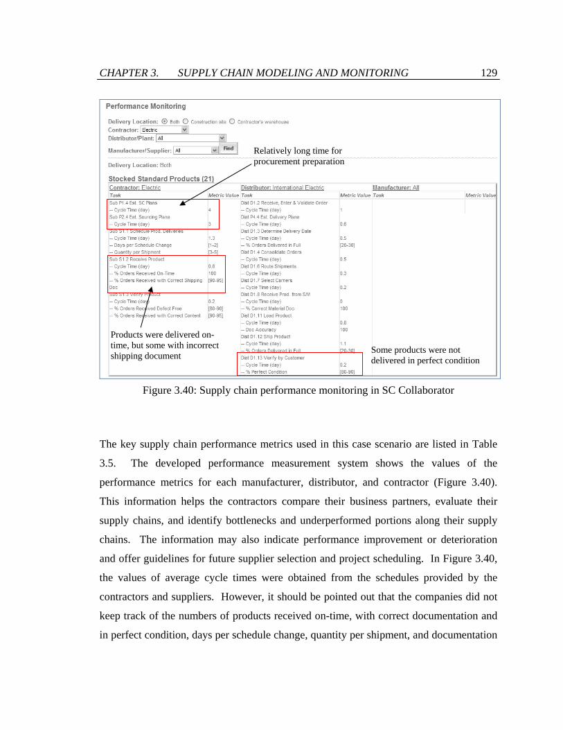
CHAPTER 3. SUPPLY CHAIN MODELING AND MONITORING 129
Figure 3.40: Supply chain performance monitoring in SC Collaborator
The key supply chain performance metrics used in this case scenario are listed in Table
3.5. The developed performance measurement system shows the values of the
performance metrics for each manufacturer, distributor, and contractor (Figure 3.40).
This information helps the contractors compare their business partners, evaluate their
supply chains, and identify bottlenecks and underperformed portions along their supply
chains. The information may also indicate performance improvement or deterioration
and offer guidelines for future supplier selection and project scheduling. In Figure 3.40,
the values of average cycle times were obtained from the schedules provided by the
contractors and suppliers. However, it should be pointed out that the companies did not
keep track of the numbers of products received on-time, with correct documentation and
in perfect condition, days per schedule change, quantity per shipment, and documentation
Relatively long time for procurement preparation
Some products were not delivered in perfect condition
Products were delivered on-time, but some with incorrect shipping document

CHAPTER 3. SUPPLY CHAIN MODELING AND MONITORING 130
accuracy in the construction project. The value ranges shown in Figure 3.40 were based
on the estimations provided by the companies.
For instance, as illustrated in Figure 3.40, only about 85% of the products that the
electrical subcontractor purchased from the distributor International Electric were
delivered in perfect condition. Perfect condition of an item means that the item meets
specification, has correct configuration, is undamaged, is accepted by the customer, is
faultlessly installed, and is not returned for repair or replacement. Imperfect condition
can be caused by poor transportation conditions, lack of communication between the
customer and the supplier, and incorrect documentations, etc. In this case, the
subcontractor and the distributor may need to find the causes and prevent further
problems.
Figure 3.40 also shows that all of the products the electrical subcontractor purchased
from the distributor International Electric were delivered on time as scheduled.
However, only nearly 95% of the received products came with correct shipping
documents, which may lead to confusion of the electrical subcontractor. The problem
should have been revealed and improved in the project or even in future collaborations.
In addition, the time that the electrical subcontractor generally spent on planning the
procurement process was relatively long compared to the duration of the whole sourcing
process. It could be difficult and subjective to draw conclusions on the length of the
planning time, but the performance measure points out a potential aspect that the
subcontractor can pay attention to and improve in the future.
3.6 Summary
This chapter demonstrates the modeling of construction supply chains using the Supply
Chain Operations Reference (SCOR) modeling framework. The mechanical, electrical
and plumbing (MEP) supply chains of a student center construction project have been

CHAPTER 3. SUPPLY CHAIN MODELING AND MONITORING 131
studied retrospectively and used as a case example. In the MEP supply chains we
studied, three major types of the construction supply chains were observed – stocked
standard products, make-to-order standard / configurable products, and custom products.
The three types of supply chains in the student center construction project are modeled
through the Level 2, Level 3, and Level 4 modeling of the SCOR framework. SCOR
Level 2 models describe the buyer-supplier interactions along supply chains. SCOR
Level 3 models specify the material flows and information flows among the Level 3
process elements involved in the supply chains. The implementation details of Level 3
process elements are captured in the SCOR Level 4 models. The SCOR Level 3 and
Level 4 models are represented in BPMN standard, which is a reader-friendly open
standard for process modeling.
This chapter also presents a model-based service oriented framework to develop a
construction supply chain performance monitoring system. The system development
framework consists of construction supply chain network, process modeling and
definition, performance metrics selection, and process execution. The framework
leverages open standards (BPMN, BPEL, WSDL, and SOAP), open source software (SC
Collaborator, MySQL, Liferay Portal, Apache Tomcat, Apache ODE, Axis2 framework,
Struts framework, and Hibernate framework), and the SCOR modeling framework. The
SCOR Level 3 and Level 4 models developed in the first part of this chapter are reused as
the baseline in the system design phase. Performance metrics are then determined in a
process-based approach for each Level 3 supply chain process element. For system
implementation, the Level 3 and Level 4 BPMN models are converted into BPEL files,
which are completed with the aid of an open source BPEL editing tool. The BPEL files
are finally incorporated in the service oriented SC Collaborator system that is presented
in Chapter 2. The modified SCOR-based SC Collaborator system allows product-based
supply chain tracking and organization-based performance monitoring, which are
demonstrated in Section 3.5.

CHAPTER 3. SUPPLY CHAIN MODELING AND MONITORING 132
The system development framework presented in this chapter uses the SCOR models as
the backbone. However, the framework is applicable to other supply chain models or
process maps. In addition, the system developed in this research is not limited to only
MEP supply chains in construction projects of medium scale. In a project of larger scale,
the supply chain relationships may be more complex because subcontractors may
subcontract some parts of their jobs to other companies. This results in layers of
subcontractors each of which is associated with its supply chains with different trading
partners. In this case, modifications of the structures and layouts in the SC Collaborator
system are needed to meet the actual project needs. However, the system in general can
be applied to various types of construction supply chains and to projects of various sizes.

Chapter 4
Distributed SC Collaborator Network
4.1 Introduction
In current collaborative systems, data and documents are commonly stored, managed, and
shared in a centralized manner because it facilitates data management and reduces the
possibility of data inconsistency. However, information sharing and application
integration may be hindered in such centralized systems because some project
participants may be reluctant to share information with other participants who do not
have direct business relationship. Sharing of information requires mutual trust, which is
often difficult to establish among participants in construction projects due to the
temporary project-based business relationships. The SC Collaborator system presented in
Chapter 2 is a centralized portal system with a single shared database. Despite the
security and access control capability of the portal-based system, supply chain members
may still be uncomfortable to provide proprietary information for sharing in a system that
non-trading partners can physically connect to.
CHAPTER 4. DISTRIBUTED SC COLLABORATOR NETWORK 134
The ownership problem of the shared information is also a common issue for centralized
collaborative systems. In a construction project, systems for information and document
sharing are commonly installed and hosted in machines that are managed by the general
contractor. Contractors and suppliers that do not have direct business relationship with
the general contractor may hesitate to provide their information and documents to the
general contractor for hosting. Sometimes third party companies are employed to host
and manage the collaborative systems throughout a project. When the project is
completed, however, how to handle the shared information and documents and who has
the rights to own them are often ambiguous and controversial. In addition, companies
only have a limited control on the shared data if they are hosted by a third party.
These privacy and ownership problems can be alleviated by separating a centralized
system into a distributed network of systems. In such a distributed network, individual
project members own and manage their information and applications and, at the same
time, share the information and applications with designated project partners at specific
time period. Whenever the project finishes or the trading relationship ends, project
members can terminate the connections of other project participants to their systems. In
this way, people may feel more secure of their proprietary assets and become more
willing to share their information, system operations and services.
Establishing a framework for the distributed network is a non-trivial task. Security and
information consistency among distributed systems should be maintained. Concurrency
and sequencing of the connections across the systems should be facilitated. In this
chapter, we will discuss these technical issues and present a distributed network of
service oriented portal-based systems.
This chapter is organized as follows. Section 4.2 shows the communication between
distributed SC Collaborator systems. Section 4.3 discusses the security protection
provided for the service units deployed in a SC Collaborator system. Section 4.4 presents
the measures in SC Collaborator to ensure information consistency among service units

CHAPTER 4. DISTRIBUTED SC COLLABORATOR NETWORK 135
in distributed SC Collaborator system. Section 4.5 demonstrates the distributed SC
Collaborator network with a procurement scenario and a rescheduling scenario.
4.2 Distributed SC Collaborator Network
Architecture
Figure 4.1 shows the schematic representation of a centralized SC Collaborator system
and a distributed SC Collaborator network. In the distributed network architecture, each
organization has its own database and SC Collaborator system. Each individual SC
Collaborator system can act as an intranet and content management system internally,
while at the same time allows information exchange and sharing over the web. As
illustrated in Figure 4.1, a centralized SC Collaborator system is conventionally used to
integrate loosely coupled applications and to share information among project
participants from different organizations. The database and the SC Collaborator system
are hosted by either one organization or a third party company. With the centralized
architecture, individual organizations may hesitate to upload and share their sensitive
information depending on their level of trust. On the contrary, for the distributed network
architecture as shown in Figure 4.1, the storage and ownership of information are
distributed among enterprises and users. They can grant the rights to view or access their
own proprietary data and documents to particular collaborating partners for a specific
period of time. The distributed systems thus provide better control of the shared
information. With the distributed network architecture, enterprises may become more
willing to coordinate and share their proprietary information.
The communication between individual SC Collaborator systems is achieved using
standardized web service technologies and languages. As illustrated in Figure 4.2, the
business implementation core supports the invocation of web services through
standardized SOAP. The Apache Axis2 framework allows information, applications, and
operations to be exposed and deployed as web services. The deployed functionalities are

CHAPTER 4. DISTRIBUTED SC COLLABORATOR NETWORK 136
described using standardized WSDL language for discovery and invocation. The
connectivity between separate SC Collaborator portal systems can be easily created as
long as the address of the deployed web services is given.
Figure 4.1: Centralized SC Collaborator system versus distributed SC Collaborator
network
General Contractor WSDL
Axis2Struts
Portal
Business core Sec
urity
Subcontractors
WSDL
Axis2 Struts
Portal
Business core
Secu
rity
SuppliersWSDL
Axis2 Struts
Portal
Business core
Sec
urity
SOAP
SOAP
SOAP
BPEL
BPEL
SuppliersWSDL
Axis2Struts
Portal
Business core Sec
urity
BPEL
BPEL
SOAP
SOAP
Figure 4.2: System architecture for communications among individual SC Collaborator
systems
Deployed web
services
SC Collaborator
Enterprises A B C
Users
DB
A B C
Centralized Distributed
DB DB
DB

CHAPTER 4. DISTRIBUTED SC COLLABORATOR NETWORK 137
4.3 Service Security
Security and information consistency are the key issues that a distributed collaborative
system network needs to tackle. Security can be performed on the data layer and/or the
networking layer. In the former approach, data is manipulated by security functions in
the applications before being transmitted from a sender to a receiver. In the latter
approach, security is provided by the communication network protocol such as Secure
Sockets Layer (SSL). In SC Collaborator, the former approach is adopted and we have
developed a layer for access control for the internally deployed web service units.
The web service units can be exposed in a secure way. Each web service unit is treated
as a resource with separate permission information, which is stored at the back-end
database. Successful authentication with correct user ID and password is required to
invoke the service units for data retrieval and application operations. The user ID and
password share the same profile with the accounts in SC Collaborator. In other words,
the system administrator can manage the access rights to the deployed web services by
managing the accounts in SC Collaborator using the administrator portlet. The access
rights are established or removed when the corresponding SC Collaborator account is
created or deleted. This ensures a consistent access control to the portal system as well as
the exposed functionalities.
Since the portal user interface keeps track of the user information after a user logs in the
system, the application portlet units can obtain the user identification and check the
profiles assigned to the user before invoking web service units in a different SC
Collaborator system. The associations between users and external service unit profiles
are managed by system administrators and are hidden from the front-end user
perspective. The functions to change and to query the associations are deployed as an
internal web service unit. Each SC Collaborator system also provides a password
protected page for system administrator to check the service operations available for a
particular profile, as illustrated in Figure 4.3.

CHAPTER 4. DISTRIBUTED SC COLLABORATOR NETWORK 138
Figure 4.3: Password protected web page allowing users with successful authentication to
view available web service units
Successful authentication
Unsuccessful authentication

CHAPTER 4. DISTRIBUTED SC COLLABORATOR NETWORK 139
4.4 Information Consistency
Information consistency is a major issue for collaborations among distributed information
sources. In a construction project, for example, project participants may have different
copies of the design documents circulating among each other. If the design documents
are managed in a centralized system, different participants are guaranteed to obtain the
same version of the documents if they connect to the system at the same time. On the
contrary, if participants are allowed to obtain a design document from multiple sources,
the document that a participant obtains may have a different version from the document
obtained by another participant. Therefore, although information and documents are
stored and managed in different locations in a distributed SC Collaborator network, they
are referenced from a single source in order to maintain consistency. For example, the
project schedule is solely provided by the general contractor while the work schedule
information is offered by the subcontractors.
To maintain information consistency among distributed information sources, a business
process service should be designed to act as a discrete transaction and to achieve the
ACID properties (i.e. atomicity, consistency, isolation, and durability) [69]. The ACID
properties provide requirements on concurrency and fault-handling behavior of a service.
For atomicity, a service performs as a single logical unit and ensures that either all or
none of its components are executed when the service terminates. For consistency, a
service either creates a new valid state of data, or rolls back and restores to a state
satisfying the consistency rules on the data. For isolation, other operations cannot access
or see the data in an intermediate state during the processing of a service. For durability,
a service saves the committed data so that changes in the data persist once the user has
been notified of success of service completion.

CHAPTER 4. DISTRIBUTED SC COLLABORATOR NETWORK 140
4.4.1 Consistency Issues in Distributed System Networks
A composite process service requires invocation to distributed service components over
the network and is vulnerable to network connection failures. Furthermore, a composite
process service usually has limited control on the component services which are located
and managed in different systems. Therefore, it is challenging for a composite process
service in a distributed system network to achieve the ACID properties.
Consider a business process service that changes the project schedule and updates the
work schedules of individual contractors. This service is invoked when project managers
submit a new proposed project schedule with revised task starting dates. In this example,
contractors do not share their full work schedules because they may be involved in other
projects. Instead, the contractors distribute the work schedule information as web service
units “Work Schedule Service” that allow business partners to inquire their availability in
a specific time period. Figure 4.4 shows the Java implementation class of the operations
“checkAvailability” and “changeTaskDates” in the service unit Work Schedule Service.
As illustrated in Figure 4.4, the “checkAvailability” operation receives input parameters
of a starting date and a finishing date and checks the number of task events in the work
schedule in the time period between the two dates. If there is no task event in the time
period, the “checkAvailability” operation returns a “true” value; otherwise, a value of
false is returned. The “changeTaskDates” operation receives a task number, a starting
date, a finishing date, and task information. The operation then removes all the task
events labeled with the input task number, and adds new task events in the time period
between the input starting date and finishing date.

CHAPTER 4. DISTRIBUTED SC COLLABORATOR NETWORK 141
public class WorkScheduleService { public availabilityType checkAvailability (String start, String finish, String taskId, String requestedBy) { availabilityType output = new availabilityType(); try { Class.forName("com.mysql.jdbc.Driver").newInstance(); Connection conn = DriverManager.getConnection("jdbc:mysql://localhost:3306/portal","",""); Statement stmt = conn.createStatement(); ResultSet rs = stmt.executeQuery("SELECT count(eventId) FROM calevent WHERE startDate>='"+start+"' AND startDate<='"+finish+"' AND title NOT LIKE '"+taskId+" -'"); rs.next(); SimpleDateFormat dbDateFormat = new SimpleDateFormat("yyyy-MM-dd"); if (dbDateFormat.parse(finish).getTime()>=dbDateFormat.parse(start).getTime() && rs.getInt(1)==0) output.available=true; else output.available=false; } catch (Exception e) { } return output; } public void changeTaskDates(String newStart, String newFinish, String taskId, String title, String description, String requestedBy) { try { Class.forName("com.mysql.jdbc.Driver").newInstance(); Connection conn = DriverManager.getConnection("jdbc:mysql://localhost:3306/portal","",""); Statement stmt = conn.createStatement(); ArrayList<String> eventIds = new ArrayList<String>(); ResultSet rs = stmt.executeQuery("SELECT eventId FROM calevent WHERE title like '"+ taskId+" -'"); while (rs.next()) eventIds.add(rs.getString("eventId")); for (int i = 0; i < eventIds.size(); i++) { stmt.execute("DELETE FROM calevent WHERE eventId='"+eventIds.get(i)+"'"); stmt.execute("DELETE FROM resource_ WHERE codeId='3503' AND primKey='"+eventIds.get(i)+"'"); } SimpleDateFormat dbDateFormat = new SimpleDateFormat("yyyy-MM-dd"); if (dbDateFormat.parse(newFinish).getTime()>=dbDateFormat.parse(newStart).getTime()) { Calendar calendar1 = Calendar.getInstance(); calendar1.setTime(dbDateFormat.parse(newStart)); int eventId = 15000; int resourceId = 44800; rs = stmt.executeQuery("SELECT max(eventId) FROM calevent"); if (rs.next()) eventId = rs.getInt(1)+1; rs = stmt.executeQuery("SELECT max(resourceId) FROM resource_"); if (rs.next()) resourceId = rs.getInt(1)+1; while (! newFinish.equals(dbDateFormat.format(calendar1.getTime()))) { stmt.execute("INSERT INTO calevent VALUES ('"+ eventId+ "','14901','10095', '10112','Jack Cheng',now(),now(),'"+taskId+" - "+title+"','"+description+" - "+requestedBy+"','"+ dbDateFormat.format(calendar1.getTime())+ "','"+dbDateFormat.format(calendar1.getTime())+ " 23:59:59',24,0,1,0,'site- work',0,'','none',300000,300000);"); stmt.execute("INSERT INTO resource_ VALUES ('"+resourceId+"','3503','"+ eventId+"');"); calendar1.add(Calendar.DATE, 1); eventId++; resourceId++; } stmt.execute("INSERT INTO calevent VALUES ('"+eventId+"','14901','10095', '10112','Jack Cheng',now(),now(),'"+taskId+" - "+title+"','"+description+" - "+requestedBy+"','"+dbDateFormat.format(calendar1.getTime())+"','"+ dbDateFormat.format(calendar1.getTime())+" 23:59:59',24,0,1,0,'site- work',0,'','none',300000,300000);"); stmt.execute("INSERT INTO resource_ VALUES ('"+resourceId+"','3503','"+ eventId+"');"); } } catch (Exception e) { } } }
Figure 4.4: Java implementation class of the service unit Work Schedule Service
Find the number of tasks in a specific time period
Available if there is no task in the time period and the time period length is positive
Obtain the task events associated with the specific task
Delete the task events
Add a task event for each day, and register the event in the system

CHAPTER 4. DISTRIBUTED SC COLLABORATOR NETWORK 142
Figure 4.5: Business service that changes project schedule and updates individual
distributed work schedules
As illustrated in Figure 4.5, the process service that changes a project schedule first
invokes the distributed Work Schedule Service units deployed by individual contractors
to check their work availability. If the new project schedule satisfies the work schedules
of all the contractors, the process service updates the project schedule residing in the
system, and modifies the individual work schedules using the service operation
“changeTaskDates” in individual Work Schedule Service units. Otherwise, the project
schedule and work schedules are not changed.
Consider a simple case scenario that swaps the schedules of two tasks performed by
different contractors. Task 1 is performed from September 14, 2009 to September 18,
2009 by Subcontractor 1 while Task 2 is performed from September 21, 2009 to
September 25, 2009 by Subcontractor 2. The pseudo code of the processes executed by
the schedule changing process is shown in Figure 4.6. Figure 4.7 shows the BPEL
process that changes the project schedule as well as the work schedules of
Subcontractor 1 and Subcontractor 2. The process invokes the “checkAvailability”
operation of Subcontractor 1 and checks its availability from September 21 to
September 25. The process also invokes the “checkAvailability” operation of
Contractor 1 WSDL
Contractor 2
Contractor N
: :
WSDL
WSDL
1. Check contractors’ availability through their work schedules
Work schedule Project schedule
2. Continue if new schedule satisfies all contractors’ work schedule
3. Change project schedule
4. Change contractors’ work schedules
5. Return notifications
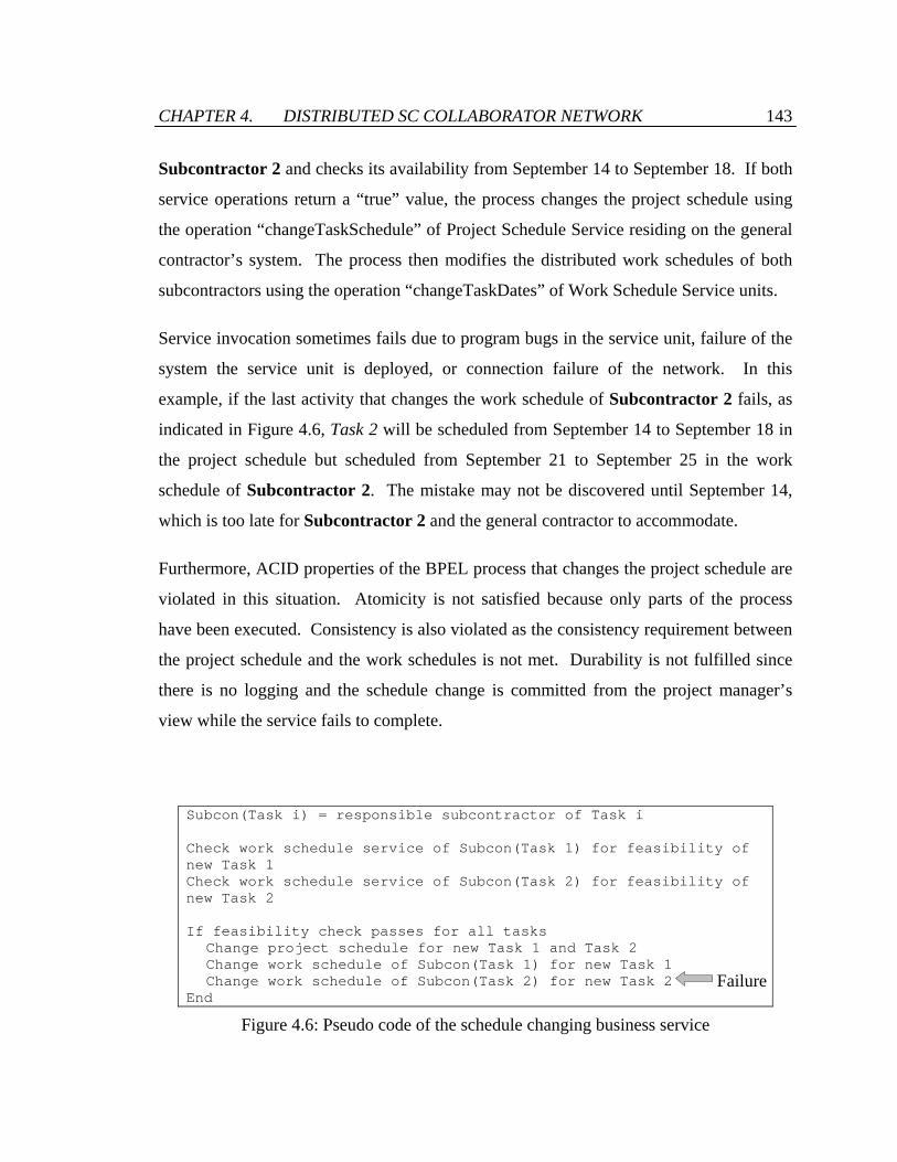
CHAPTER 4. DISTRIBUTED SC COLLABORATOR NETWORK 143
Subcontractor 2 and checks its availability from September 14 to September 18. If both
service operations return a “true” value, the process changes the project schedule using
the operation “changeTaskSchedule” of Project Schedule Service residing on the general
contractor’s system. The process then modifies the distributed work schedules of both
subcontractors using the operation “changeTaskDates” of Work Schedule Service units.
Service invocation sometimes fails due to program bugs in the service unit, failure of the
system the service unit is deployed, or connection failure of the network. In this
example, if the last activity that changes the work schedule of Subcontractor 2 fails, as
indicated in Figure 4.6, Task 2 will be scheduled from September 14 to September 18 in
the project schedule but scheduled from September 21 to September 25 in the work
schedule of Subcontractor 2. The mistake may not be discovered until September 14,
which is too late for Subcontractor 2 and the general contractor to accommodate.
Furthermore, ACID properties of the BPEL process that changes the project schedule are
violated in this situation. Atomicity is not satisfied because only parts of the process
have been executed. Consistency is also violated as the consistency requirement between
the project schedule and the work schedules is not met. Durability is not fulfilled since
there is no logging and the schedule change is committed from the project manager’s
view while the service fails to complete.
Subcon(Task i) = responsible subcontractor of Task i Check work schedule service of Subcon(Task 1) for feasibility of new Task 1 Check work schedule service of Subcon(Task 2) for feasibility of new Task 2 If feasibility check passes for all tasks Change project schedule for new Task 1 and Task 2 Change work schedule of Subcon(Task 1) for new Task 1 Change work schedule of Subcon(Task 2) for new Task 2 End
Figure 4.6: Pseudo code of the schedule changing business service
Failure

CHAPTER 4. DISTRIBUTED SC COLLABORATOR NETWORK 144
<bpel:process name="ChangeScheduleService" targetNamespace="http://localhost:8080/service/process/ChangeScheduleService" xmlns:bpel="http://docs.oasis-open.org/wsbpel/2.0/process/executable" xmlns:ns="http://ws.apache.org/axis2"> <bpel:import location="ChangeScheduleServiceArtifacts.wsdl" importType="http://schemas.xmlsoap.org/wsdl/" /> <bpel:partnerLinks> <bpel:partnerLink name="client" partnerLinkType="tns:ChangeScheduleService" myRole="ChangeScheduleServiceProvider" /> <bpel:partnerLink name="WorkSchedule1" partnerLinkType="tns:WorkSchedulePLT" partnerRole="ServiceProvider"></bpel:partnerLink> <bpel:partnerLink name="WorkSchedule2" partnerLinkType="tns:WorkSchedule2PLT" partnerRole="ServiceProvider"></bpel:partnerLink> <bpel:partnerLink name="ProjectSchedule" partnerLinkType="tns:ProjectSchedulePLT" partnerRole="ServiceProvider"></bpel:partnerLink> </bpel:partnerLinks> <bpel:variables> <bpel:variable name="input" messageType="tns:ChangeScheduleServiceRequestMessage"/> <bpel:variable name="output" messageType="tns:ChangeScheduleServiceResponseMessage"/> <bpel:variable name="WorkSchedule1Response" messageType="ns:checkAvailabilityResponse"/> <bpel:variable name="WorkSchedule1Request" messageType="ns:checkAvailabilityRequest"/> <bpel:variable name="ProjectScheduleRequest" messageType="ns:changeTaskScheduleRequest"/> <bpel:variable name="WorkSchedule1Response1" messageType="ns:changeTaskDatesResponse"/> <bpel:variable name="WorkSchedule1Request1" messageType="ns:changeTaskDatesRequest"/> </bpel:variables> <bpel:sequence name="main"> <bpel:receive name="receiveInput" partnerLink="client" portType="tns:ChangeScheduleService" operation="process" variable="input" createInstance="yes"/> <bpel:flow name="Check work schedules"> <bpel:invoke name="Check work schedule 1" partnerLink="WorkSchedule1" operation="checkAvailability" portType="ns:WorkScheduleService2PortType" inputVariable="WorkSchedule1Request" outputVariable="WorkSchedule1Response"/> <bpel:invoke name="Check work schedule 2" partnerLink="WorkSchedule2" operation="checkAvailability" portType="ns:WorkScheduleService2PortType" inputVariable="WorkSchedule1Request" outputVariable="WorkSchedule1Response"/> </bpel:flow> <bpel:if name="If"> <bpel:sequence name="Modify schedules"> <bpel:invoke name="Change project schedule" partnerLink="ProjectSchedule" operation="changeTaskSchedule" portType="ns:ProjectScheduleServicePortType" inputVariable="ProjectScheduleRequest"/> <bpel:invoke name="Change work schedule 1" partnerLink="WorkSchedule1" operation="changeTaskDates" portType="ns:WorkScheduleService2PortType" inputVariable="WorkSchedule1Request1" outputVariable="WorkSchedule1Response1"/> <bpel:invoke name="Change work schedule 2" partnerLink="WorkSchedule2" operation="changeTaskDates" portType="ns:WorkScheduleService2PortType" inputVariable="WorkSchedule1Request1" outputVariable="WorkSchedule1Response1"/> </bpel:sequence> </bpel:if> <bpel:reply name="replyOutput" partnerLink="client" portType="tns:ChangeScheduleService" operation="process" variable="output" /> </bpel:sequence> </bpel:process>
Figure 4.7: The BPEL process that changes a project schedule

CHAPTER 4. DISTRIBUTED SC COLLABORATOR NETWORK 145
4.4.2 Implementation in SC Collaborator
To maintain the ACID properties in a distributed SC Collaborator network, three
modifications are made to the system framework:
• Modification of web service units so that transaction service operations return a
response message that contains information about their roll-back operations.
Modification of data service operations is not required because they only provide
data without making changes to any underlying data.
• Creation of a Process-in-Progress (PIP) table in the back-end database to keep
records of the on-going processes in the system. There are three service
operations on the PIP table – (1) an operation that adds the specifications of the
invoked service operations and the information about roll-back operations to the
PIP table for temporary storage, (2) an operation that removes all the PIP records
of a particular process after process completion, and (3) an operation that reads
the PIP records and undoes the changes made by web service units invoked in the
process. These operations are wrapped and deployed as service operations
“addRecord”, “removeRecord” and “restoreState” respectively in a web service
unit PIP Service, which BPEL processes can easily invoke and execute. Figure
4.8 shows the Java implementation class of the PIP Service. As illustrated in
Figure 4.8, the operation “restoreState” receives a BPEL process identification
number and extracts all the PIP records that are related to the process and contain
a value of “Return” in the Notes column. For every extracted record, the specified
roll-back service operation is invoked to undo the modifications previously made
in the process. A notification is returned when all the roll-back service operations
are successfully called.
• Modification of the BPEL process unit so that every invocation of transaction
service operation is enclosed in a BPEL scope activity that contains elements for
logging and fault handling.

CHAPTER 4. DISTRIBUTED SC COLLABORATOR NETWORK 146
public class PIPService { public String addRecord(String processId, String targetNamespace, String serviceName, String serviceLocation, String operation, String parameters, String notes) { ... } public String removeRecord(String processId) { ... } public String restoreState(String processId) { String notification = "Error"; try { Class.forName("com.mysql.jdbc.Driver").newInstance(); Connection conn = DriverManager.getConnection("jdbc:mysql://localhost:3306/portal","",""); Statement stmt = conn.createStatement(); ResultSet rs = stmt.executeQuery("SELECT recordId, time, targetNamespace, serviceName, serviceLocation, operation, parameters, notes FROM PIP WHERE processId=\'"+processId+"\' ORDER BY recordId desc"); ServiceClient serviceClient = new ServiceClient(); while (rs.next()) { String targetNamespace = rs.getString("targetNamespace"); String serviceName = rs.getString("serviceName"); String serviceLocation = rs.getString("serviceLocation"); String operation = rs.getString("operation"); String parameters = rs.getString("parameters"); String notes = rs.getString("notes"); if (notes.equals("Return") && !targetNamespace.equals("") && !serviceName.equals("") && !serviceLocation.equals("") && !operation.equals("")) { OMFactory fac = OMAbstractFactory.getOMFactory(); OMNamespace omNs = fac.createOMNamespace(targetNamespace, "eig"); OMElement payload = fac.createOMElement(serviceName, omNs); String[] elements = parameters.split("!"); OMElement value; for (int i = 0; i < elements.length; i++) { value = fac.createOMElement(elements[i].split(":")[0].trim(), omNs); value.setText(elements[i].split(":")[1].trim()); payload.addChild(value); } serviceClient = new ServiceClient(); Options options = new Options(); options.setTo(new EndpointReference(serviceLocation)); options.setAction(operation); serviceClient.setOptions(options); serviceClient.sendRobust(payload); } } serviceClient.cleanup(); conn.close(); notification = "Success"; } catch (Exception e) { } return notification; } }
Figure 4.8: Java implementation class of the service unit PIP Service
Obtain all the PIP records for a particular process
Invoke service units to restore the original state
Returns a notification when all the service units are successfully restored
Service operations

CHAPTER 4. DISTRIBUTED SC COLLABORATOR NETWORK 147
Figure 4.9: Maintaining information consistency in a distributed SC Collaborator network
With these three system modifications, information consistency is maintained among
distributed SC Collaborator systems, as illustrated in Figure 4.9. Before a web service
unit is invoked in a BPEL process, its service specification information (i.e. target
namespace, service name, service location, operations, parameter names, and parameter
values) is stored through the operation “addRecord” of PIP Service unit. The BPEL
business process then invokes the web service unit and provides the parameter values.
The web service unit is modified and returns a notification which contains information
about the operation to roll back the modifications made by the service unit.
If the BPEL process receives a notification from the invoked service unit, it means that
the service invocation is successful. The BPEL process then extracts the roll-back
information from the notification and enters it into the PIP table. Otherwise, the fault
handling component in the BPEL process will be triggered. The fault handler invokes the
operation “restoreState” in PIP Service unit to undo the modifications previously made
by the BPEL process.
Scope in BPEL
Logging
Service
invocation
Web service
unit
Record Time Process Name-space Service name Service
location Operation Parameters Notes
… … … … … … … … … 3 … Sch94 http://... changeTaskDates http://... changeTaskDates […] Sent 4 … Sch94 http://... changeTaskDates http://... changeTaskDates […] Return
… … … … … … … … … New parameter values
Old parameter values Roll back operation
Notification processing
Fault handling
1
2 3
4b Web service unit
Web service unit
Web service unit 4a
5a 6a
Database
Process-in-Progress (PIP) Table
PIP Service unit restoreState

CHAPTER 4. DISTRIBUTED SC COLLABORATOR NETWORK 148
Consider the simple scenario that swaps the schedules of two tasks, Task 1 and Task 2.
Three system modifications are performed as follows.
• The implementations of the service units Work Schedule Service and Project
Schedule Service are modified to return roll-back information in a response
message. Figure 4.10 shows the Java implementation class of the modified Work
Schedule Service. To roll back a change of task schedule, an operation that
changes the task schedule back to its original value is needed. Therefore, the
operation “changeTaskDates” of Work Schedule Service is the roll-back
operation of itself. As illustrated in Figure 4.10, the modified service operation
“changeTaskDates” obtains the old task schedule information before making
changes to the data. The old task schedule information and the service
specification of the operation “changeTaskDates” are returned in the response
message, in a data structure of “notificationType” as described in Figure 4.11.
• PIP table is created in the back-end database and the corresponding PIP Service
unit is deployed in the SC Collaborator system of the general contractor.
• The BPEL process that changes a project schedule is modified. The invoke
activities “Change project schedule”, “Change work schedule 1” and “Change
work schedule 2” are enclosed in separate scope activities because the operation
“changeTaskSchedule” of Project Schedule Service and the operation
“changeTaskDates” of Work Schedule Service are transaction service operations.
The activity “Change work schedule 2” is a simple BPEL invoke activity in the
original BPEL process, as highlighted in Figure 4.7. As illustrated in Figure 4.12,
the activity is enclosed in a scope in the new BPEL process. Before the activity is
performed, the operation “addRecord” of the PIP Service is invoked to record the
input parameters of the activity “Change work schedule 2.” If the activity is
successfully performed, the operation “addRecord” is called again to record the
roll-back information returned. Otherwise, the operation “restoreState” of PIP
Service is called to undo all the changes previously done by the BPEL process.

CHAPTER 4. DISTRIBUTED SC COLLABORATOR NETWORK 149
public notificationType changeTaskDates(String newStart, String newFinish, String taskId, String title, String description, String requestedBy) { notificationType output = new notificationType(); output.notes = "Error"; try { Class.forName("com.mysql.jdbc.Driver").newInstance(); Connection conn = DriverManager.getConnection("jdbc:mysql://localhost:3306/portal","",""); Statement stmt = conn.createStatement(); SimpleDateFormat dbDateFormat = new SimpleDateFormat("yyyy-MM-dd"); SimpleDateFormat dbDateFormat2 = new SimpleDateFormat("yyyy-MM-dd HH:mm:ss "); ResultSet rs = stmt.executeQuery("SELECT title, description, startDate FROM calevent WHERE title like '"+taskId+" -' ORDER BY startDate asc"); String title2 = ""; String description2 = ""; String start = ""; String finish = ""; if (rs.next()) { title2 = rs.getString("title").replace(taskId+" - ", ""); description2 = rs.getString("description").replace(" - "+requestedBy, ""); start = dbDateFormat.format(dbDateFormat2.parse(rs.getString("startDate"))); finish = start; } while (rs.next()) finish = dbDateFormat.format(dbDateFormat2.parse(rs.getString("startDate"))); ArrayList<String> eventIds = new ArrayList<String>(); rs = stmt.executeQuery("SELECT eventId FROM calevent WHERE title like '"+taskId+" - '"); while (rs.next()) eventIds.add(rs.getString("eventId")); for (int i = 0; i < eventIds.size(); i++) { stmt.execute("DELETE FROM calevent WHERE eventId='"+eventIds.get(i)+"'"); stmt.execute("DELETE FROM resource_ WHERE codeId='3503' AND primKey='"+eventIds.get(i)+"'"); } if (dbDateFormat.parse(newFinish).getTime()>=dbDateFormat.parse(newStart).getTime()) { Calendar calendar1 = Calendar.getInstance(); calendar1.setTime(dbDateFormat.parse(newStart)); int eventId = 15000; int resourceId = 44800; rs = stmt.executeQuery("SELECT max(eventId) FROM calevent"); if (rs.next()) eventId = rs.getInt(1)+1; rs = stmt.executeQuery("SELECT max(resourceId) FROM resource_"); if (rs.next()) resourceId = rs.getInt(1)+1; while (! newFinish.equals(dbDateFormat.format(calendar1.getTime()))) { stmt.execute("INSERT INTO calevent VALUES ('"+eventId+"','14901','10095', '10112','Jack Cheng',now(),now(),'"+taskId+" - "+title+"','"+description+" - "+requestedBy+"','"+dbDateFormat.format(calendar1.getTime())+"','"+ dbDateFormat.format(calendar1.getTime())+" 23:59:59',24,0,1,0,'site- work',0,'','none', 300000,300000);"); stmt.execute("INSERT INTO resource_ VALUES ('"+resourceId+"','3503','"+ eventId+"');"); calendar1.add(Calendar.DATE, 1); eventId++; resourceId++; } : } output.notes = "Success"; output.targetNamespace = "http://ws.apache.org/axis2"; output.serviceName = "changeTaskDates"; output.serviceLocation = "WorkScheduleService2"; output.operation = "changeTaskDates"; output.params = "start:" + start + "!finish:" + finish + "!taskId:" + tasked + "!title:" + title2 + "!description:" + description2 + "!requestedBy:" + requestedBy; } catch (Exception e) { } return output; }
Figure 4.10: Java implementation class of the modified Work Schedule Service
It will be changed to “Success” at the end
Obtain the original state of information
Obtain the associated task events
Add a task event for each day, and register the event in the system
Assign the original state of information to the output response

CHAPTER 4. DISTRIBUTED SC COLLABORATOR NETWORK 150
public class notificationType { String notes = ""; String targetNamespace = ""; String serviceName = ""; String serviceLocation = ""; String operation = ""; String params = ""; public String getNotes() { return notes; } public void setNotes(String notes) { this.notes = notes;} public String getTargetNamespace() { return targetNamespace; } : ]
Figure 4.11: Java class for data type “notificationType”
<bpel:scope name="Scope"> <bpel:sequence> <bpel:invoke name="addRecord" partnerLink="PIP" operation="addRecord" portType="ns:PIPServicePortType" inputVariable="PIPRequest1" outputVariable="PIPResponse1" /> <bpel:invoke name="Change work schedule 2" partnerLink="WorkSchedule2" operation="changeTaskDates" portType="ns:WorkScheduleService2PortType" inputVariable="WorkSchedule1Request1" outputVariable="WorkSchedule1Response1"/> <bpel:invoke name="addRecord" partnerLink="PIP" operation="addRecord" portType="ns:PIPServicePortType" inputVariable="PIPRequest2" outputVariable="PIPResponse2" /> </bpel:sequence> <bpel:variables> <bpel:variable name="PIPResponse" messageType="ns:addRecordResponse"/> <bpel:variable name="PIPRequest" messageType="ns:addRecordRequest"/> <bpel:variable name="PIPResponse1" messageType="ns:addRecordResponse"/> <bpel:variable name="PIPRequest1" messageType="ns:addRecordRequest"/> <bpel:variable name="PIPResponse2" messageType="ns:removeRecordResponse"/> <bpel:variable name="PIPRequest2" messageType="ns:removeRecordRequest"/> </bpel:variables> <bpel:faultHandlers> <bpel:catch> <bpel:invoke name="restoreState" partnerLink="PIP" operation="restoreState" portType="ns:PIPServicePortType" inputVariable="PIPRequest" outputVariable="PIPResponse" /> </bpel:catch> </bpel:faultHandlers> </bpel:scope>
Figure 4.12: BPEL codes showing activity “Change work schedule 2” in a scope
Information for rollback

CHAPTER 4. DISTRIBUTED SC COLLABORATOR NETWORK 151
With the modifications described above, information consistency can be maintained even
though the activity “Change work schedule 2” fails unexpectedly. Figure 4.13 depicts the
situation when all the distributed service units are invoked successfully in the BPEL
process. The activity “Change project schedule” adds a PIP record, invokes the operation
“changeTaskSchedule” of the Project Schedule Service unit in the local system, obtains
the roll-back information returned from the service operation “changeTaskSchedule,” and
enters the information in the PIP table. The activity “Change work schedule 1” then adds
a PIP record, invokes the operation “changeTaskDates” of the Work Schedule Service
unit in the SC Collaborator system hosted by Subcontractor 1, obtains the roll-back
information which includes the old work schedule data, and enters the information in the
back-end PIP table. The activity “Change work schedule 2” interacts with the Work
Schedule Service unit of Subcontractor 2 and the PIP Service unit in the local system
similarly. Finally, the PIP records for the BPEL process are removed by calling the
operation “removeRecord” of the PIP Service unit.
Figure 4.13: Interactions in distributed SC Collaborator network when the BPEL process
that changes a project schedule completes successfully
Subcontractor 1 Work Schedule
Service unit
Subcontractor 2
Work Schedule Service unit
PIP Table
General Contractor
PIP Service unit
BPEL process Project Schedule Service unit
end
start
check
Invoke(change-TaskSchedule)
Return
addRecord
removeRecord
Web services units
DB
addRecord
addRecord
1
2
3
45 8
Invoke (changeTaskDates)
6
Return 7
9 12Invoke (changeTaskDates)
Return
10
11 13
newStart=“2009-09-21”newFinish=“2009-09-25”taskId=“2038 title=“…”
params= “newStart:2009-09-14!newFinish:2009-09-18!taskId=2038!title:…”
Change proj schedule
Change work schedule 1
Change work schedule 2

CHAPTER 4. DISTRIBUTED SC COLLABORATOR NETWORK 152
Figure 4.14: Interactions in distributed SC Collaborator network when the activity
“Change work schedule 2” fails
Consider the situation that the activity “Change work schedule 2” fails, probably due to
system failure of Subcontractor 2 or deployment problem of the Work Schedule Service
unit, as illustrated in Figure 4.14. The BPEL process does not receive a response
message from the Work Schedule Service unit of Subcontractor 2, resulting in a fault
message for the service invocation in the activity “Change work schedule 2.” The BPEL
process catches the fault message and invokes the operation “restoreState” of the PIP
Service unit. The operation “restoreState” then invokes the service operations
“changeTaskDates” of Subcontractor 1 and “changeTaskSchedule” of the local system
with the old schedule information to restore the original state of the project schedule and
work schedules.
Among the four ACID requirements in a distributed network of systems, service
atomicity is achieved because the BPEL process unit performs as a single logical unit and
either all or none of its components are executed when the process terminates.
Consistency is also achieved because the original valid states of the schedules are
restored at the end. Moreover, durability is fulfilled since the PIP records can be played
back to recreate the system states right before a failure.
Subcontractor 1 Work Schedule
Service unit
Subcontractor 2
Work Schedule Service unit
PIP Table
General Contractor
PIP Service unit
BPEL process Project Schedule Service unit
end
start
check
Invoke(change- TaskSchedule)
Return
addRecord
Web services units
DB
addRecord
1
2
3
45 8
Invoke (changeTaskDates)
6
Return 7
Invoke (changeTaskDates)
Return
10
11
newStart=“2009-09-21”newFinish=“2009-09-25”taskId=“2038” title=“…”
params= “newStart:2009-09-14!newFinish:2009-09-18!taskId=2038!title:…”
Invoke (change-TaskSchedule)
14
addRecord 9
12restoreState
Invoke (changeTaskDates)
13
newStart=“2009-09-14” newFinish=“2009-09-18”taskId=“2038” title=“…”
Change proj schedule
Change work schedule 1
Change work schedule 2

CHAPTER 4. DISTRIBUTED SC COLLABORATOR NETWORK 153
4.5 Scenario Demonstration on the Distributed SC
Collaborator Network
In this section, a three-storey residential building as shown in Figure 4.15 is used as a
case scenario to demonstrate the implementation of a distributed SC Collaborator
network. In the project, the capacity of the building was expanded from 24 to 46 rooms.
In this scenario, the general contractor is responsible for windows and doors installation.
There are three subcontractors of interest, which are responsible for installation of wall
façades, room interiors, and mechanical, electrical and plumbing components (Figure
4.16). The general contractor, subcontractors, and suppliers have their own SC
Collaborator systems running and collaborating with each other. The first demonstration
is a procurement example between contractors and suppliers while the second
demonstration shows a project-wide collaboration for a material delivery delay.
Figure 4.15: 3D model of the three-storey residential building

CHAPTER 4. DISTRIBUTED SC COLLABORATOR NETWORK 154
Figure 4.16: Organizations involved in the example scenario
4.5.1 E-Procurement
The benefits of electronic procurement have been discussed in Section 2.6.1. In the
demonstration in Section 2.6.1, e-Procurement is performed in a centralized manner in
SC Collaborator. Documents such as purchase orders of different suppliers are stored
and shared together in a single database. This is not practical in a real supply chain
application because many suppliers are willing to share their purchase orders and detailed
product information with their direct trading partners only. Purchase orders contain
suppliers’ price information and delivery decisions. Suppliers may be able to deduce the
pricing strategy and inventory management techniques of competitors from their
purchase orders. A construction project may involve multiple suppliers that provide
similar products and/or services. As opposed to a centralized system, a distributed
system network can promote collaboration and information sharing among supply chain
members.
GenCon [General contractor]
Anderson [Window]
Petom [Window/door]
Apex Wall [Wall facade]
Kent Interiors [Drywall]
Rivab [Wall supplier]
Cedar MEP [Mechanical, electrical & plumbing]
Suppliers Subcontractors

CHAPTER 4. DISTRIBUTED SC COLLABORATOR NETWORK 155
In this demonstration example, the general contractor GenCon uses Autodesk ADT
program as the interface for project management. The CAD program is implemented
with a database which stores the building information models of every design. In a
model-based CAD framework, each design object (e.g. door, window, and slab) is
associated with information related to the product, the supplier, the corresponding task,
and so on. An ADT plug-in SpecifiCAD developed by CADalytic Media, Inc. is
leveraged to interact with the design objects in an ADT drawing and to retrieve the
underlying building information. The plug-in displays web pages written in Java Service
Pages (JSP) language which can connect to databases using Java Database Connectivity
(JDBC) and to web services using standardized SOAP. As shown in Figure 4.17, when
GenCon selects a window object in the 3D model of the residential building, the project
information including its price and supplier information is displayed in the plug-in.
Figure 4.17: Original product information of the selected window
Supplier: Petom
Product Name: 200 Series Tilt-Wash Double-Hung Windows
Price: $350
Autodesk ADT CADalytic SpecifiCAD

CHAPTER 4. DISTRIBUTED SC COLLABORATOR NETWORK 156
Suppliers may offer different prices and discounts to different customers. In this
scenario, suppliers provide customized catalogs to their partners through standardized
web services protocol. When GenCon selects a window object in Autodesk ADT and
clicks the “Catalog” tab in SpecifiCAD interface, the server connects to the extranet of
supplier partners and searches their catalogs with keyword “window” and the product
name. As illustrated in Figure 4.18, three supplier partners return results with hyperlinks
directing to the company websites. GenCon can refer to the product websites and
replace the existing window object in the drawing with the ones shown in the search
results by simply clicking the “Apply” button. As demonstrated in Figure 4.18, the
supplier Anderson in the example scenario sells the same window product but at a
cheaper price than the original one. GenCon therefore replaces the window object and
the product model information at the back-end is updated instantaneously (Figure 4.19).
GenCon’s SC Collaborator shares the same company database with the model-based
CAD program. When the architectural design is finalized, the purchasing officers of
GenCon can log in their SC Collaborator system and submit electronic purchase orders
to various suppliers (Figure 4.20). The suppliers use different SC Collaborator systems
to manage and respond their received purchase orders (Figure 4.21).

CHAPTER 4. DISTRIBUTED SC COLLABORATOR NETWORK 157
Figure 4.18: Inquiry to window supplier partners
Figure 4.19: Updated product information of the selected window
Information obtained from Extranet via Web services
Supplier: Anderson
Product Name: 200 Series Tilt-Wash Double-Hung Windows
Price: $278
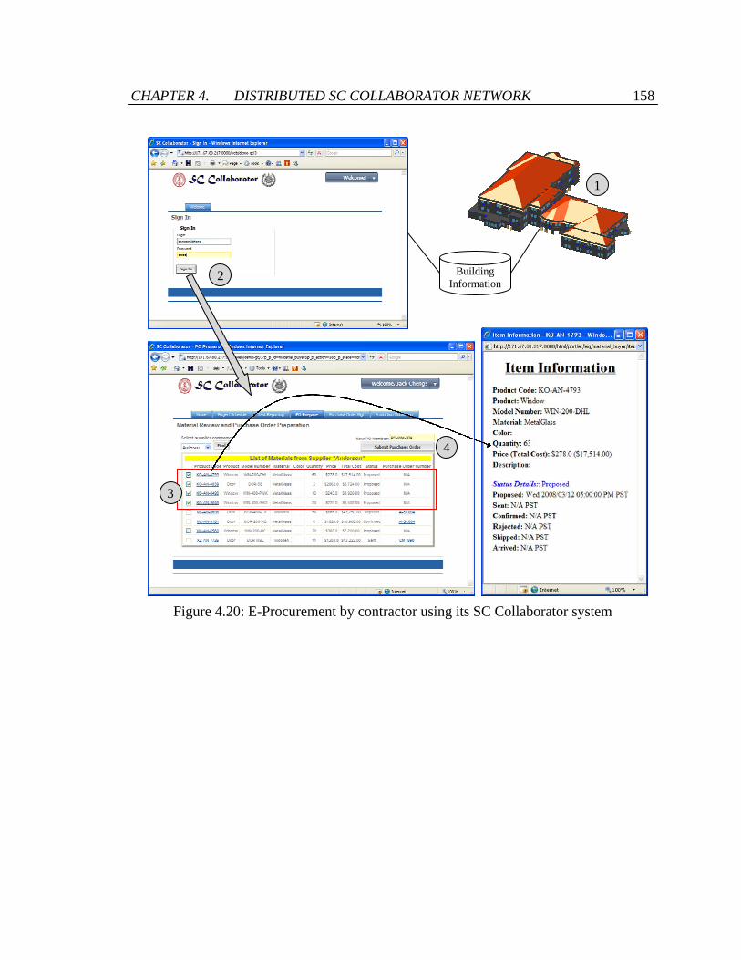
CHAPTER 4. DISTRIBUTED SC COLLABORATOR NETWORK 158
Figure 4.20: E-Procurement by contractor using its SC Collaborator system
Building Information
1
2
3
4

CHAPTER 4. DISTRIBUTED SC COLLABORATOR NETWORK 159
Figure 4.21: Supplier managing and responding received purchase orders using its SC
Collabroator system
4.5.2 Responding to Material Delivery Delay
This example demonstrates the collaboration and chain reactions among general
contractor, subcontractors, and suppliers to respond to delivery problem of a key
material. In this example, as illustrated in Figure 4.22, schedule information is
distributed among general contractor, subcontractors, and suppliers in a distributed SC
Collaborator network. The general contractor and the subcontractors keep their on-site
work schedules internally. The general contractor also provides the project schedule to
all the subcontractors. The suppliers manage their production and delivery schedules in
their own systems. These schedule information are wrapped and delivered as individual
web service units in separate SC Collaborator systems. The general contractor,
subcontractors, and suppliers can share schedule information to designated participants
21
3
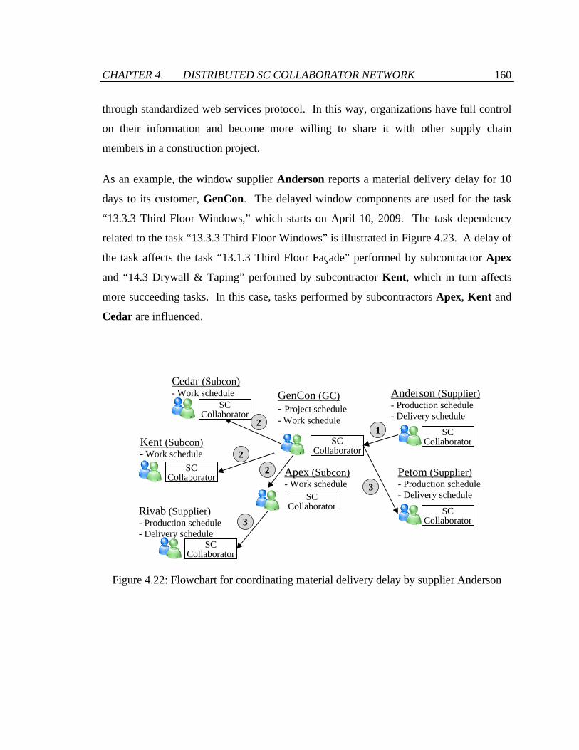
CHAPTER 4. DISTRIBUTED SC COLLABORATOR NETWORK 160
through standardized web services protocol. In this way, organizations have full control
on their information and become more willing to share it with other supply chain
members in a construction project.
As an example, the window supplier Anderson reports a material delivery delay for 10
days to its customer, GenCon. The delayed window components are used for the task
“13.3.3 Third Floor Windows,” which starts on April 10, 2009. The task dependency
related to the task “13.3.3 Third Floor Windows” is illustrated in Figure 4.23. A delay of
the task affects the task “13.1.3 Third Floor Façade” performed by subcontractor Apex
and “14.3 Drywall & Taping” performed by subcontractor Kent, which in turn affects
more succeeding tasks. In this case, tasks performed by subcontractors Apex, Kent and
Cedar are influenced.
Figure 4.22: Flowchart for coordinating material delivery delay by supplier Anderson
GenCon (GC) - Project schedule - Work schedule
Cedar (Subcon) - Work schedule
Kent (Subcon) - Work schedule
Apex (Subcon) - Work schedule
Anderson (Supplier)- Production schedule - Delivery schedule
SC Collaborator
Petom (Supplier) - Production schedule- Delivery schedule
Rivab (Supplier) - Production schedule - Delivery schedule
SC Collaborator
SC Collaborator
SC Collaborator
SC Collaborator
SC Collaborator
SC Collaborator
1
2
2
2
3
3

CHAPTER 4. DISTRIBUTED SC COLLABORATOR NETWORK 161
Figure 4.23: Originial project schedule
…

CHAPTER 4. DISTRIBUTED SC COLLABORATOR NETWORK 162
GenCon generates multiple alternative project schedules, which are displayed in the
application portlet unit for changing the project schedule as shown in Figure 4.24. The
tasks which need to be changed are indicated on the “Status” column in the display.
GenCon can make the changes described in the alternative project schedule by simply
clicking the “Apply” button in the portlet unit. The button triggers a BPEL process unit
that changes the project schedule and the distributed work schedules of the affected
subcontractors, which is illustrated in Figure 4.25. The process unit connects to the
affected subcontractors (Apex, Kent and Cedar in this case), and checks their
availability for each modified tasks by invoking the operation “checkAvailability” of the
Work Schedule Service unit in their systems. If a “true” value is returned for all the
modified tasks, the operation “changeTaskDates” is invoked for each task. When the
process completes, the BPEL process invokes the operation “removeRecord” of PIP
Service to clear its PIP records.
After the change of project schedule is confirmed, GenCon and other subcontractors
could change the target delivery date of other materials corresponding to the task
postponed. The changes of target delivery date of other materials propagate to GenCon’s
suppliers who may adjust their production and planned delivery date accordingly.
Maintenance of information consistency is tested in this example. When GenCon
invokes the BPEL process unit that changes the project schedule and the work schedules
of Apex, Kent and Cedar, the SC Collaborator system of Kent is shut down for testing
purpose. When invoking the “checkAvailability” operation of the Work Schedule
Service unit in Kent’s SC Collaborator system, the service operation returns a SOAP
response message describing a connection fault, as illustrated in Figure 4.26, which is
captured in the BPEL process. Since the BPEL process does not obtain a “true” value for
all the modified tasks, it terminates without changing the project schedule and work
schedules. Information consistency is achieved.

CHAPTER 4. DISTRIBUTED SC COLLABORATOR NETWORK 163
Figure 4.24: Application portlet unit in general contractor’s layout that displays
alternative project schedules
…

CHAPTER 4. DISTRIBUTED SC COLLABORATOR NETWORK 164
<bpel:process name="ChangeScheduleService2" targetNamespace="http://localhost:8080/service/processes/ChangeScheduleService2" xmlns:bpel="http://docs.oasis-open.org/wsbpel/2.0/process/executable"> <bpel:import location="ChangeScheduleService2Artifacts.wsdl" importType="http://schemas.xmlsoap.org/wsdl/" /> <bpel:partnerLinks> <bpel:partnerLink name="WorkScheduleApex" partnerLinkType="tns:WorkSchedulePLT" partnerRole="ServiceProvider" /> : <bpel:partnerLink name="PIP" partnerLinkType="tns:PIPPLT" partnerRole="ServiceProvider" /> </bpel:partnerLinks> <bpel:variables> ... </bpel:variables> <bpel:sequence name="main"> <bpel:receive name="receiveInput" partnerLink="client" portType="tns:ChangeScheduleService2" operation="process" variable="input" /> <bpel:forEach parallel="no" counterName="Counter" name="ForEach"> <bpel:scope> <bpel:sequence> <bpel:if name="Select contractor"> <bpel:invoke name="Check availability Apex" partnerLink="WorkScheduleApex" operation="checkAvailability" portType="ns:WorkScheduleService2ApexPortType" inputVariable="WorkScheduleApexRequest" outputVariable="WorkScheduleApexResponse"/> <bpel:elseif> <bpel:invoke name="Check availability Kent" partnerLink="WorkScheduleKent" operation="checkAvailability" portType="ns:WorkScheduleService2KentPortType" inputVariable="WorkScheduleKentRequest" outputVariable="WorkScheduleKentResponse"/> </bpel:elseif> <bpel:elseif> <bpel:invoke name="Check availability Cedar" partnerLink="WorkScheduleCedar" operation="checkAvailability" portType="ns:WorkScheduleService2CedarPortType" inputVariable="WorkScheduleCedarRequest" outputVariable="WorkScheduleCedarResponse"/> </bpel:elseif> </bpel:if> </bpel:sequence> <bpel:variables> <bpel:variable name="WorkScheduleApexResponse" messageType="ns:checkAvailabilityResponse"/> : </bpel:variables> </bpel:scope> </bpel:forEach> <bpel:if name="If"> <bpel:sequence> <bpel:scope name="Scope"> <bpel:sequence> <bpel:invoke name="add Record" partnerLink="PIP" operation="addRecord" portType="ns:PIPServicePortType" /> <bpel:invoke name="Change project schedule" partnerLink="ProjectSchedule" operation="changeTaskSchedule" portType="ns:ProjectScheduleServicePortType" inputVariable="ProjectScheduleRequest" /> <bpel:invoke name="addRecord" partnerLink="PIP" operation="addRecord" portType="ns:PIPServicePortType" /> </bpel:sequence> <bpel:variables> ... </bpel:variables> <bpel:faultHandlers> <bpel:catch> ... </bpel:catch> </bpel:faultHandlers> </bpel:scope> <bpel:forEach parallel="no" counterName="Counter" name="ForEach1"> <bpel:scope> <bpel:if name="Select contractor"> <bpel:sequence> <bpel:scope name="Scope"> : <bpel:invoke name="Change work schedule Apex" partnerLink="WorkScheduleApex" operation="changeTaskDates" portType="ns:WorkScheduleService2ApexPortType" /> </bpel:scope> </bpel:sequence> <bpel:elseif> ... </bpel:elseif> </bpel:if> </bpel:scope> </bpel:forEach> </bpel:sequence> </bpel:if> <bpel:invoke name="removeRecord" partnerLink="PIP" operation="removeRecord" portType="ns:PIPServicePortType" /> <bpel:reply name="replyOutput" partnerLink="client" portType="tns:ChangeScheduleService2" operation="process" variable="output" /> </bpel:sequence> </bpel:process>
Figure 4.25: BPEL process that changes the project schedule and the distributed work
schedules in the scenario demonstration
Checks the availability of Apex, Kent and Cedar for each modified task
Changes the project schedule
Changes the distributed work schedules
Removes PIP records

CHAPTER 4. DISTRIBUTED SC COLLABORATOR NETWORK 165
<?xml version='1.0' encoding='UTF-8'?> <soapenv:Envelope xmlns:soapenv="http://schemas.xmlsoap.org/soap/envelope/"> <soapenv:Body> <soapenv:Fault> <faultcode>soapenv:Client</faultcode> <faultstring> The service cannot be found for the endpoint reference (EPR) http://171.67.80.70:8080/service/processes/WorkScheduleService </faultstring> <detail> <Exception> org.apache.axis2.AxisFault: The service cannot be found for the endpoint reference (EPR) http://171.67.80.70:8080/service/processes/WorkScheduleService
 at org.apache.axis2.engine.DispatchPhase.checkPostConditions (DispatchPhase.java:62)
 : at java.lang.Thread.run(Thread.java:595)
 </Exception> </detail> </soapenv:Fault> </soapenv:Body> </soapenv:Envelope>
Figure 4.26: SOAP response message showing the connection fault when invoking the
Work Schedule Service unit located in Kent’s system
For further testing, the service operation “changeTaskDates” is removed from the Java
implementation class of Work Schedule Service for subcontractor Kent. The Work
Schedule Service unit is deployed again in Kent’s SC Collaborator system. When
GenCon invokes the BPEL process that changes the project schedule and work
schedules, the same SOAP fault response message as shown in Figure 4.26 is captured at
the BPEL activity “Change work schedule.” Since the activity is enclosed in a scope that
contains logging and fault handling functionalities supported by the PIP Service unit,
changes made to the project schedule and the work schedules of Apex and Cedar are
rolled back and the old schedule information is restored. As a result, the schedule
information described in the project schedule and the work schedules of Apex, Kent and
Cedar are consistent even though a service invocation failure occurs in the BPEL
process.

CHAPTER 4. DISTRIBUTED SC COLLABORATOR NETWORK 166
4.6 Summary
Current collaborative systems are mostly centralized. Business partners upload
information and documents to a single system and share with other companies. However,
this kind of collaboration does not satisfy the need in a supply chain setting. Since
supply chain management integrates members from suppliers’ suppliers to customers’
customers, companies who do not have direct business relationships are involved in the
same supply chain. Although most collaborative systems for supply chain management
provide security control to the information and applications shared in the systems, some
companies do not feel comfortable to share proprietary and privacy information and
documents in those systems. In addition, there are often debates on who has the rights to
host the systems and to keep the shared information. This chapter presents a distributed
network of service oriented collaborator systems which aim to tackle these problems.
In a distributed SC Collaborator network, companies can own and manage their
information, documents and applications in their own system, and share them with
designated partners at a specific time. The communications among distributed SC
Collaborator are supported by leveraging standardized web services technologies and
protocols. Since the internal information, applications, and system operations of the SC
Collaborator system are wrapped and deployed in individual web service units, they can
be exposed to other SC Collaborator system for invocation through the SOAP, WSDL,
and BPEL standards.
Security and information consistency are key issues for distributed collaborative systems.
The security of web service units is managed by the authentication capability provided by
the portal system interface in SC Collaborator. This chapter mainly discusses the system
architecture to maintain information consistency among distributed systems. It is
achieved by the specific design of the back-end database support, the web service units,
and the BPEL process services. The database is leveraged for logging of running process
services. The web service units return information for roll-back upon successful

CHAPTER 4. DISTRIBUTED SC COLLABORATOR NETWORK 167
invocation. The process services leverage the fault handling functionality of BPEL
standard to roll back in case of service failures. This chapter also demonstrates the
distributed SC Collaborator network for procurement and task rescheduling among
distributed systems of general contractor, subcontractors, and suppliers. Inconsistency
consistency among distributed SC Collaborator systems is also successfully tested.

Chapter 5
Conclusions and Future Works
Importance of supply chain integration and collaboration has been shown in many
industry sectors. However, the construction industry is one of the least integrated among
all major industries. The current technologies and tools for supply chain integration such
as enterprise resource planning (ERP) systems are designed for construction supply
chains, which are highly fragmented and unstable project-based in nature. This thesis
presents a system framework that addresses the requirements for managing and
integrating construction supply chains. This chapter provides a summary of the thesis,
discusses the main contributions of the thesis, and describes some future research
directions.
5.1 Summary of Research
With the proliferation of the Internet and the increasingly maturity of web services
standards, the adoption of service oriented architecture (SOA) with open source
technologies is a desirable computing model to support construction supply chain

CHAPTER 5. CONCLUSIONS AND FUTURE WORKS 169
management due to its flexibility and low cost. This thesis presents a prototype service
oriented collaborative system framework, namely SC Collaborator (Supply Chain
Collaborator), that was designed and developed to facilitate integration, collaboration,
and monitoring of construction supply chains in a flexible manner. The implementation
of SC Collaborator leverages web services and portal technologies, open standards, and
open source packages. The SC Collaborator framework consists of a database support
and four layers of integrated functionalities – a communication layer, a portal interface
layer, a business applications layer, and an extensible computing layer. The
communication layer provides a communication channel for users to access the system.
The portal interface layer serves as a secure and customizable user interface. The
business applications layer implements SOA and integrates information, applications and
services in a flexible and reusable manner. Internal information sources, application
functionalities, and system operations are wrapped and deployed into individual web
service units on this layer. The extensible computing layer may include databases,
software applications, and web services that the business applications layer can integrate
externally. The framework is tested and demonstrated in a procurement scenario and a
project rescheduling example.
This thesis demonstrates the modeling of construction supply chains and proposes the
incorporation of supply chain models in a service oriented system framework.
Specifically, the Supply Chain Operations Reference (SCOR) framework developed by
Supply Chain Council is used to model the network structure and processes in
construction supply chains. The mechanical, electrical and plumbing (MEP) supply
chains in a student center construction project has been studied and used as the case
example. Information and documents have been collected and interviews with the
general contractor, subcontractors, and suppliers have been conducted in the study. The
MEP supply chains models developed using the SCOR framework are then utilized to
build a supply chain performance monitoring system. This is achieved by wrapping each
SCOR Level 3 and Level 4 models into individual web service units, which can be
integrated and orchestrated in the service oriented SC Collaborator framework. The

CHAPTER 5. CONCLUSIONS AND FUTURE WORKS 170
development and implementation details of the SCOR-based performance monitoring
system are included in this thesis.
The SC Collaborator framework is further extended to support collaboration among
distributed SC Collaborator systems. Currently, supply chain members collaborate and
share information and operations in a centralized manner. In this way, members only
have a limited control on the information they share and the ownership of the shared
information is controversial. Project participants that do not have direct business
partnership may be reluctant to expose and share sensitive and proprietary information
with each other. This thesis thus introduces a distributed SC Collaborator network.
Communication between SC Collaborator systems is achieved through standardized web
services protocol. System modifications are made to ensure information consistency
among distributed SC Collaborator systems. Web service units are modified to return
roll-back operation information whereas BPEL processes are changed to perform logging
and fault handling for every invocation of transaction service operations. In addition,
service invocations of on-going processes are recorded at the back-end database. In this
way, consistency among distributed SC Collaborator systems can be maintained
regardless of network failures or service failures. The distributed SC Collaborator
network is tested with a case scenario of a completed expansion project of a three-storey
residential building.
5.2 Research Contributions
Integration of information and applications is one of the keys to effective supply chain
management. This thesis investigates and demonstrates the use of service oriented
architecture, web services and portal technologies, and open source tools to develop a
prototype service oriented framework that can facilitate integration and collaboration
among supply chain members. The framework supports flexible system reconfiguration

CHAPTER 5. CONCLUSIONS AND FUTURE WORKS 171
and integeration of scattered information and application operations, system alignment
based on supply chain configuration, and distributed network of collaborative systems.
The thesis also demonstrates the modeling and performance monitoring of construction
supply chains. Four major contributions are made in this thesis:
• Incorporation of supply chain models in a collaborative system framework:
This thesis proposes and demonstrates the integration of supply chain models and
web services technology in a service oriented SC Collaborator system framework.
The Supply Chain Operations Reference (SCOR) modeling framework is
employed to model and monitor construction supply chains in this research. The
SCOR framework is widely used to model supply chain network structures and
operations for strategic planning purposes. The SCOR framework is seldom
leveraged for the design and implementation of information systems for supply
chain management and collaboration. The resulting SCOR-based SC
Collaborator framework allows flexible alignment with supply chain
configuration and modular modification of the system.
• Distributed network of collaborative systems: In current collaborative systems,
members share information, documents, and operations in a centralized manner.
This thesis proposes a distributed network of collaborative systems that allows
users to fully control the data and operations they share and promotes information
sharing among supply chain members. This thesis presents a distributed SC
Collaborator network which is based on standardized web services technologies,
and addresses the information consistency issues among the distributed SC
Collaborator systems.
• A collaborative system framework that is designed for construction supply
chain management: A collaborative system that is designed to manage
construction supply chains needs (1) ease of installation and configuration, (2)
low cost, (3) ease to be connected and integrated, (4) ability to integrate external
systems and information, and (5) customizable access to information and

CHAPTER 5. CONCLUSIONS AND FUTURE WORKS 172
applications. Current solutions do not fulfill all of these requirements. To
demonstrate a SCOR-based system and a distributed network of collaborative
systems, a prototype service oriented system framework SC Collaborator is
developed. Leveraging web services and portal technologies, open source tools,
and open standards in system implementation, the SC Collaborator framework is
designed according to the five system requirements and is desirable for
construction supply chain collaboration and management. The system framework
is tested and validated through various case scenarios.
• Modeling and performance monitoring of construction supply chains: The
planning and management of supply chains require properly specifying the
participating members, identifying the relationships among them, and monitoring
their performance. However, there is no formal methodology that models and
represents the supply chain networks and operations in the construction industry.
Study on the performance monitoring of construction supply chains is also
lacking. This thesis employs the Supply Chain Operations Reference (SCOR)
modeling framework to model and monitor construction supply chains. The
mechanical, electrical and plumbing (MEP) supply chains in a student center
construction project has been studied and modeled using the SCOR framework as
a case example in this thesis. The development of a performance monitoring
platform for the MEP supply chains is also illustrated.
5.3 Future Directions
This section describes the limitations of this research and how they can be addressed in
future research.

CHAPTER 5. CONCLUSIONS AND FUTURE WORKS 173
5.3.1 Ontology Based Systems
Supply chain members may use different representations to describe the same piece of
information. Web Services Description Language (WSDL) documents specify the data
structures and data types of the elements in the request and response messages of each
web service operation. Based on WSDL, the prototype SC Collaborator framework
enables integration of information, applications, and services with different
representations. However, supply chain members may use the same terminology to
describe different concepts or use different terminology to describe the same concepts,
due to the differences in their domains and perspectives. The specifications in WSDL
documents do not provide the semantics of the data being exchanged between partners.
Misunderstanding and misinterpretation of the data may be resulted. Ontologies could be
used to describe the data semantics and to serve as a terminological basis for information
interoperability. In a system framework that is supported by both WSDL documents and
ontologies, information, applications and services can be syntactically and semantically
integrated and interoperated.
5.3.2 Extending the Research Scope on Modeling
The three configurations of MEP supply chains described in Chapter 3 are based on our
study of a student center construction project. The MEP supply chains in other
construction projects may have different configurations in terms of organizations and
business operations. The configuration of a supply chain may be affected by factors such
as the common practice of the supply chain members, the scale and budget of the project,
and the type of the construction. Further study of the MEP processes in other
construction projects may be needed to validate the generality of the three supply chain
configurations described. Moreover, the research can be extended to other kinds of
processes in a construction project, for example, steel erection and window installation to
study the supply chains involved in these processes, to model them using the SCOR

CHAPTER 5. CONCLUSIONS AND FUTURE WORKS 174
framework, and to build a performance monitoring system for these supply chains using
the framework we presented in this thesis. By extending the scope of our research, we
hope to test the developed methodology and framework and to enhance their usability.
We may also integrate the SCOR models with the existing construction process maps to
better reflect the structure and configuration in construction supply chains.
5.3.3 Application Programming Interface for SC
Collaborator
Many system and applications offer an application programming interface (API) that
enables software programs to connect to and interact with them. APIs define how other
software can make calls to or request services from them. Software programs can
interact with the SC Collaborator system through web services protocol. With successful
authentication, users can view the names of the web service units and their service
operations that are available for invocation. The list of web service units is also
hyperlinked to individual WSDL documents, which describe the service specification that
users can refer to when calling the service operations. However, SC Collaborator does
not provide a description of the behaviors and relationship of the web service units. In
the future, the behaviors and dependency of the service units and their operations will be
specified and documented. An interface that allows users to view and search the detailed
documentation should also be provided.
5.3.4 Evaluation of SC Collaborator Using TAM
Although the SC Collaborator framework has been tested and demonstrated using various
example scenarios, the value and deficiency of the framework is not evaluated and
analyzed in this thesis. Technology acceptance model (TAM) [30] can be adopted to

CHAPTER 5. CONCLUSIONS AND FUTURE WORKS 175
Figure 5.1: Technology acceptance model (TAM) [30]
evaluate SC Collaborator in terms of perceived usefulness and perceived ease of use.
TAM is an information systems theory that models how users come to accept and use a
technology. As illustrated in Figure 5.1, the perceived usefulness and ease of use of a
system affect the attitude towards using the system and the behavioral intentions to use
the system, which eventually are reflected in the actual system use. To improve the value
and impact of SC Collaborator, we will demonstrate the SC Collaborator framework to
industry practitioners and gather their feedbacks on the perceived usefulness, ease of use,
and intentions to use the system. By study the feedbacks, we can prioritize the system
features and components, and determine the most value-adding improvements we can
make.
5.3.5 Applications of the GreenSCOR Framework
There have been increasing concerns on the environmental impacts of the construction
industry. In 2008, Supply Chain Council released the GreenSCOR framework [91]
which is a generic conceptual framework for measuring the total carbon footprint and
total environmental footprint in a supply chain. As illustrated in Figure 5.2, the
GreenSCOR framework considers five performance metrics – (1) carbon footprint in tons
of carbon dioxide equivalent, (2) air pollutant emissions in tons or kg, (3) liquid waste
Perceived usefulness
Perceived ease of use
Attitude towards using
Behavioral intentions
to use
Actual system
use
External variables

CHAPTER 5. CONCLUSIONS AND FUTURE WORKS 176
generated in tons or kg, (4) solid waste generated in tons or kg, and (5) percentage of
solid waste that is recycled. Since the GreenSCOR framework is based on the SCOR
framework, it could be incorporated in the SCOR-based SC Collaborator to build a green
supply chain performance monitoring framework designed for the construction industry.
Further study on the GreenSCOR framework and its integration with the SCOR-based SC
Collaborator will be conducted.
Figure 5.2: The GreenSCOR framework [91]

Bibliography
[1] A. Abdelnur, E. Chien and S. Hepper. Java Specification Requests (JSR) 168:
Portlet Specification, Java Community Process, Sun Microsystems and IBM,
http://jcp.org/en/jsr/detail?id=168, 2003, accessed 15 October 2009.
[2] U. Acikalin, M. Kuruoglu, U. Isikdag and J. Underwood. "Evaluating the
Integrative Function of ERP Systems Used within the Construction Industry," In
A. Zarli and R. Scherer (Eds.), Ework and Ebusiness in Architecture, Engineering
and Construction, Taylor & Francis Group, London, pp. 245-254, 2009.
[3] H.A. Akkermans, P. Bogerd, E. Yücesan and L.N. van Wassenhove. "The Impact
of ERP on Supply Chain Management: Exploratory Findings from a European
Delphi Study," European Journal of Operational Research, 146 (2), pp. 284-301,
2003.
[4] M. Al-Mashari. "Constructs of Process Change Management in ERPContent: A
Focus on SAP R/3," In Proceedings of 2000 Americas Conference on Information
Systems, AMCIS 2000, pp. 977-980, 2000.
[5] ANSI ASC. Electronic Data Interchange X12 Standards, http://www.x12.org/,
1992, accessed 19 September 2007.
[6] Apache Software Foundation, Apache Tomcat 5.5, http://tomcat.apache.org/,
2007, accessed 21 July 2007.

BIBLIOGRAPHY 178
[7] Apache Software Foundation, Apache Axis2, http://ws.apache.org/axis2/, 2007,
accessed 18 November 2008.
[8] Apache Software Foundation, Apache Struts, http://struts.apache.org, 2008,
accessed 28 June 2008.
[9] Apache Software Foundation, Apache Orchestration Director Engine (ODE),
http://ode.apache.org/, 2008, accessed 18 March 2009.
[10] BEA Systems, IBM, Microsoft, SAP and Siebel Systems. Business Process
Execution Language for Web Services (BPEL4WS), Version 1.1,
ftp://www6.software.ibm.com/software/developer/library/ws-bpel.pdf, 2003,
accessed October 18, 2006.
[11] B. Becerik. "A Review on Past, Present and Future of Web Based Project
Management & Collaboration Tools and Their Adoption by the US AEC
Industry," International Journal of IT in Architecture, Engineering and
Construction, 2 (3), pp. 233-248, 2004.
[12] B. Benatallah, M. Dumas and Q.Z. Sheng. "Facilitating the Rapid Development
and Scalable Orchestration of Composite Web Services," Distributed and Parallel
Databases, 17 (1), pp. 5-37, 2005.
[13] D. Besemer, P. Butterworth, L. Clément, J. Green, H. Ramachandra, J. Schneider
and H. Vandervoort. An Implementor's Guide to Service Oriented Architecture -
Getting It Right, Westminster Promotions, USA, 2008.
[14] P. Bingi, M.K. Sharma and J.K. Godla. "Critical Issues Affecting an ERP
Implementation," In J.M. Myerson (Ed.), Enterprise Systems Integration,
Auerbach Publications, CPC Press, pp. 425-438, 2001.

BIBLIOGRAPHY 179
[15] U.S. Bititci, A.S. Carrie and L. McDevitt. "Integrated Performance Measurement
Systems: A Development Guide," International Journal of Operations and
Production Management, 17, pp. 522-535, 1997.
[16] D. Bowersox, D. Closs and T. Stank. "How to Master Cross-Enterprise
Collaboration," Supply Chain Management Review, 7 (4), pp. 18-29, 2003.
[17] G. Briscoe and A. Dainty. "Construction Supply Chain Integration: An Elusive
Goal," Supply Chain Management: An International Journal, 10 (4), pp. 319-326,
2005.
[18] Bureau of Economic Analysis. Gross Domestic Product (GDP) by Industry 1998-
2008 NAICS Data, US Department of Commerce,
http://www.bea.gov/industry/xls/GDPbyInd_VA_NAICS_1998-2008.xls, 2009,
accessed 07 September 2009.
[19] S.L. Chan and N.N. Leung. "Prototype Web-Based Construction Project
Management System," Journal of Construction Engineering and Management,
130, pp. 935-943, 2004.
[20] H.M. Chen and H.C. Tien. "Application of Peer-to-Peer Network for Real-Time
Online Collaborative Computer-Aided Design," Journal of Computing in Civil
Engineering, 21, pp. 112-121, 2007.
[21] J. Cheng. A Simulation Access Language and Framework with Applications to
Project Management, Ph.D. Thesis, Department of Civil and Environmental
Engineering, Stanford University, Stanford, CA, 2004.
[22] S.O. Cheung, H.C.H. Suen and K.K.W. Cheung. "PPMS: A Web-Based
Construction Project Performance Monitoring System," Automation in
Construction, 13 (3), pp. 361-376, 2004.
BIBLIOGRAPHY 180
[23] M. Christopher and H. Lee. "Mitigating Supply Chain Risk through Improved
Confidence," International Journal of Physical Distribution & Logistics
Management, 34 (5), pp. 388-396, 2004.
[24] B. Chung, M.J. Skibniewski and Y.H. Kwak. "Developing ERP Systems Success
Model for the Construction Industry," Journal of Construction Engineering and
Management, 135 (3), pp. 207-216, 2009.
[25] B.Y. Chung, M.J. Skibniewski, H.C. Lucas and Y.H. Kwak. "Analyzing
Enterprise Resource Planning System Implementation Success Factors in the
Engineering–Construction Industry," Journal of Computing in Civil Engineering,
22 (6), pp. 373-382, 2008.
[26] A. Cox. "A Research Agenda for Supply Chain and Business Management
Thinking," Supply Chain Management: An International Journal, 4 (4), pp. 209-
211, 1999.
[27] A.R.J. Dainty, G.H. Briscoe and S.J. Millett. "Subcontractor Perspectives on
Supply Chain Alliances," Construction Management and Economics, 19 (8), pp.
841-848, 2001.
[28] A.R.J. Dainty, G.H. Briscoe and S.J. Millett. "New Perspectives on Construction
Supply Chain Integration," Supply Chain Management: An International Journal,
6 (4), pp. 163-173, 2001.
[29] T.H. Davenport. "Putting the Enterprise into the Enterprise System," Harvard
Business Review, 76 (4), pp. 121-131, 1998.
[30] F.D. Davis. "Perceived Usefulness, Perceived Ease of Use, and User Acceptance
of Information Technology," MIS Quarterly, 13 (3), pp. 319-340, 1989.
[31] Eclipse Foundation, BPMN Modeler, Version 0.8.0,
http://www.eclipse.org/bpmn/, 2008, accessed 25 April 2009.

BIBLIOGRAPHY 181
[32] Eclipse Foundation, BPEL Visual Designer, Version 0.4.0,
http://www.eclipse.org/bpel/, 2009, accessed 25 April 2009.
[33] M.A. Emmelhainz. Electronic Data Interchange: A Total Management Guide,
Van Nostrand Reinhold Co., New York, NY, USA, 1989.
[34] A. Fearne and N. Fowler. "Efficiency Versus Effectiveness in Construction
Supply Chains: The Dangers of Lean Thinking in Isolation," Supply Chain
Management: An International Journal, 11 (4), pp. 283-287, 2006.
[35] D. Greenwood, M. Calisti, W.T. Ag and S. Zurich. "Engineering Web Service -
Agent Integration," In Proceedings of 2004 IEEE International Conference on
Systems, Man and Cybernetics, pp. 1918-1925, 2004.
[36] A. Gunasekaran and B. Kobu. "Performance Measures and Metrics in Logistics
and Supply Chain Management: A Review of Recent Literature (1995–2004) for
Research and Applications," International Journal of Production Research, 45
(12), pp. 2819-2840, 2007.
[37] A. Gunasekaran, C. Patel and R.E. McGaughey. "A Framework for Supply Chain
Performance Measurement," International Journal of Production Economics, 87
(3), pp. 333-347, 2004.
[38] A. Gunasekaran, C. Patel and E. Tirtiroglu. "Performance Measures and Metrics
in a Supply Chain Environment," International Journal of Operations and
Production Management, 21 (1), pp. 71-87, 2001.
[39] W. Hausman. "Supply Chain Performance Metrics," In T.P. Harrison, H.L. Lee
and J.J. Neale (Eds.), The Practice of Supply Chain Management: Where Theory
and Application Converge, pp. 61-73, 2004.

BIBLIOGRAPHY 182
[40] C.A. Hill and G.D. Scudder. "The Use of Electronic Data Interchange for Supply
Chain Coordination in the Food Industry," Journal of Operations Management,
20 (4), pp. 375-387, 2002.
[41] A. Horvath. "Construction Materials and the Environment," Annual Review of
Environment and Resources, 29, pp. 181-204, 2004.
[42] S.H. Huan, S.K. Sheoran and G. Wang. "A Review and Analysis of Supply Chain
Operations Reference (SCOR) Model," Supply Chain Management: An
International Journal, 9 (1), pp. 23-29, 2004.
[43] R.R.A. Issa, I. Flood and G. Caglasin. "A Survey of E-Business Implementation
in the US Construction Industry," Journal of Information Technology in
Construction, 8, pp. 15-28, 2003.
[44] M.S. Jayashankar, F.S. Stephen and M.S. Norman. "Modeling Supply Chain
Dynamics: A Multiagent Approach," Decision Sciences, 29 (3), pp. 607-632,
1998.
[45] F. Kaefer and E. Bendoly. "The Adoption of Electronic Data Interchange: A
Model and Practical Tool for Managers," Decision Support Systems, 30 (1), pp.
23-32, 2000.
[46] M. Kagioglou, R. Cooper and G. Aouad. "Performance Management in
Construction: A Conceptual Framework," Construction Management and
Economics, 19 (1), pp. 85-95, 2001.
[47] M. Kantor and J.H. Burrows. "Electronic Data Interchange (EDI)," National
Institute of Standards and Technology (NIST),
http://www.itl.nist.gov/fipspubs/fip161-2.htm, 1996, accessed 08 June 2006.
BIBLIOGRAPHY 183
[48] J.P.C. Kleijnen and M.T. Smits. "Performance Metrics in Supply Chain
Management," Journal of the Operational Research Society, 54 (5), pp. 507-514,
2003.
[49] V. Kumar, B. Maheshwari and U. Kumar. "ERP Systems Implementation: Best
Practices in Canadian Government Organizations," Government Information
Quarterly, 19 (2), pp. 147-172, 2002.
[50] V. Kumar, B. Maheshwari and U. Kumar. "An Investigation of Critical
Management Issues in ERP Implementation: Emperical Evidence from Canadian
Organizations," Technovation, 23 (10), pp. 793-807, 2003.
[51] D.M. Lambert. Supply Chain Management: Processes, Partnerships,
Performance, Supply Chain Management Institute, 2008.
[52] D.M. Lambert and M.C. Cooper. "Issues in Supply Chain Management,"
Industrial Marketing Management, 29 (1), pp. 65-83, 2000.
[53] D.M. Lambert, M.C. Cooper and J.D. Pagh. "Supply Chain Management:
Implementation Issues and Research Opportunities," International Journal of
Logistics Management, 9 (2), pp. 1-19, 1998.
[54] D.M. Lambert and T.L. Pohlen. "Supply Chain Metrics," International Journal of
Logistics Management, 12 (1), pp. 1-20, 2001.
[55] H.L. Lee and C. Billington. "Managing Supply Chain Inventory: Pitfalls and
Opportunities," Sloan Management Review, 33 (3), pp. 65-73, 1992.
[56] H.L. Lee and C. Billington. "The Evolution of Supply-Chain-Management
Models and Practice at Hewlett-Packard," Interfaces, pp. 42-63, 1995.

BIBLIOGRAPHY 184
[57] H.L. Lee, V. Padmanabhan and S. Whang. "Information Distortion in a Supply
Chain: The Bullwhip Effect," Management Science, 50 (12 Supplement), pp.
1875-1886, 2004.
[58] H.L. Lee and S. Whang. "Supply Chain Integration over the Internet," In J.
Geunes, P.M. Pardalos and H.E. Romeijn (Eds.), Supply Chain Management:
Models, Applications, and Research Directions, Springer US, pp. 3-17, 2005.
[59] F. Leymann. Web Services Flow Language (WSFL), IBM Software Group,
http://xml.coverpages.org/WSFL-Guide-200110.pdf, 2001, accessed 16 May
2009.
[60] Liferay, Liferay Open Source Enterprise Portal System, http://www.liferay.com/,
2008, accessed 21 July 2007.
[61] K. London, R. Kenley and A. Agapiou. "Theoretical Supply Chain Network
Modelling in the Building Industry," In Proceedings of Association of
Researchers in Construction Management (ARCOM) 14th Annual Conference,
pp. 369-379, 1998.
[62] P.E.D. Love, F. Edum-Fotwe and Z. Irani. "Management of Knowledge in Project
Environments," International Journal of Project Management, 21 (3), pp. 155-
156, 2003.
[63] P.E.D. Love and Z. Irani. "An Exploratory Study of Information Technology
Evaluation and Benefits Management Practices of SMEs in the Construction
Industry," Information & Management, 42 (1), pp. 227-242, 2004.
[64] E. Luening. "Can Construction Industry Rise to Online Challenge?,"
http://www.news.com/2100-1017-244233.html, 2000, accessed 10 March 2008.
BIBLIOGRAPHY 185
[65] Z. Maamar, S.K. Mostéfaoui and H. Yahyaoui. "Toward an Agent-Based and
Context-Oriented Approach for Web Services Composition," IEEE Transactions
on Knowledge and Data Engineering, 17 (5), pp. 686-697, 2005.
[66] D. Michelinakis. Open Source Content Management Systems: An Argumentative
Approach, Master Thesis, Warwick Manufacturing Group, University of
Warwick, 2004.
[67] J.U. Min. Supply Chain Visualization through Web Services Integration, Ph.D.
Thesis, Department of Civil and Environmental Engineering, Stanford University,
Stanford, CA, 2004.
[68] E.A. Morash and S.R. Clinton. "Supply Chain Integration: Customer Value
through Collaborative Closeness Versus Operational Excellence," Journal of
Marketing Theory and Practice, 6 (4), pp. 104-120, 1998.
[69] S. Mullender. Distributed Systems, Addison Wesley, 1993.
[70] F.F.H. Nah, J.L.S. Lau and J. Kuang. "Critical Factors for Successful
Implementation of Enterprise Systems," Business Process Management Journal,
7 (3), pp. 285-296, 2001.
[71] S.J. New. "The Scope of Supply Chain Management Research," Supply Chain
Management: An International Journal, 2 (1), pp. 15-22, 1997.
[72] P. Nitithamyong and M.J. Skibniewski. "Web-Based Construction Project
Management Systems: How to Make Them Successful?," Automation in
Construction, 13 (4), pp. 491-506, 2004.
[73] W. O'Brien, L. Soibelman and G. Elvin. "Collaborative Design Processes: An
Active-and Reflective-Learning Course in Multidisciplinary Collaboration,"
Journal of Construction Education, 8 (2), pp. 78-93, 2003.

BIBLIOGRAPHY 186
[74] W.J. O'Brien, K. London and R. Vrijhoef. "Construction Supply Chain Modeling:
A Research Review and Interdisciplinary Research Agenda," In Proceedings of
the 10th Annual Conference of the International Group for Lean Construction
(IGLC-10), pp. 129-148, 2002.
[75] W. O’Brien. "Construction Supply-Chains: Case Study, Integrated Cost and
Performance Analysis," In L. Alarcon (Ed.), Lean Construction, A.A. Balkema
Publishers, Rotterdam, pp. 187-222, 1997.
[76] J. Oakland and M. Marosszeky. Total Quality in the Construction Supply Chain,
Elsevier, Oxford, Great Britain, 2006.
[77] Object Management Group (OMG). Unified Modeling Language (UML), Version
2.0, http://www.uml.org/, 2005, accessed 26 January 2009.
[78] Object Management Group (OMG). Business Process Modeling Notation
(BPMN), Version 1.1, http://www.bpmn.org/Documents/BPMN_1-
1_Specification.pdf, 2008, accessed 25 April 2009.
[79] Open Source Initiative. "The Open Source Definition,"
http://www.opensource.org/docs/osd, 2007, accessed 15 September 2009.
[80] Organization for the Advancement of Structured Information Standards (OASIS).
Web Services Business Process Execution Language (WS-BPEL), Version 2.0,
http://docs.oasis-open.org/wsbpel/2.0/OS/wsbpel-v2.0-OS.html, 2007, accessed
08 April 2009.
[81] A. Rai, R. Patnayakuni and N. Seth. "Firm Performance Impacts of Digitally
Enabled Supply Chain Integration Capabilities," Management Information
Systems Quarterly, 30 (2), pp. 225-246, 2006.
[82] S.S. Rao. "Enterprise Resource Planning: Business Needs and Technologies,"
Industrial Management and Data Systems, 100 (1), pp. 81-88, 2000.

BIBLIOGRAPHY 187
[83] Red Hat, Hibernate Framework, http://www.hibernate.org, 2008, accessed 28
June 2008.
[84] RosettaNet. The RosettaNet Standard, http://www.rosettanet.org/, 1998, accessed
06 August, 2008.
[85] M.R. Sanders. "What Does E-Marketplace Buying Cost," Tech Strategy,
Forrester Research, 2001.
[86] J.J. Shi and D.W. Halpin. "Enterprise Resource Planning for Construction
Business Management," Journal of Construction Engineering and Management,
129 (2), pp. 214-221, 2003.
[87] T.M. Simatupang, A.C. Wright and R. Sridharan. "The Knowledge of
Coordination for Supply Chain Integration," Business Process Management
Journal, 8 (3), pp. 289-308, 2002.
[88] R.D. Sriram. Distributed and Integrated Collaborative Engineering Design,
Sarven Publishers, 2002.
[89] Sun Microsystems, JDBC Data Access API, 2002.
[90] Sun Microsystems, MySQL 5.0, http://www.mysql.com, 2007, accessed 21 July
2007.
[91] Supply Chain Council (SCC). Supply Chain Operations Reference (SCOR)
Model, Version 9.0, 2008.
[92] S. Thatte. XLANG: Web Services for Business Process Design, Microsoft
Corporation, http://xml.coverpages.org/XLANG-C-200106.html, 2001, accessed
18 October 2006.

BIBLIOGRAPHY 188
[93] M. Themistocleous, Z. Irani, R.M. O’Keefe and R. Paul. "ERP Problems and
Application Integration Issues: An Empirical Survey," In Proceedings of the 34th
Annual Hawaii International Conference on System Sciences, 2001.
[94] UN/CEFACT and Organization for the Advancement of Structured Information
Standards (OASIS). Electronic Business Using eXtensible Markup Language
(ebXML), Version 1.01, 2001.
[95] D.M. Upton and A. McAfee. "The Real Virtual Factory," In D. Tapscott (Ed.),
Creating Value in the Network Economy, Harvard Business School Press, pp. 69-
89, 1999.
[96] US Air Force. Integrated Computer-Aided Manufacturing (ICAM) Architecture
Part II, Vol. IV - Function Modelling Manual (IDEF0), Report AFWAL-TR-81-
4023, Air Force Materials Laboratory, Wright-Patterson AFB, Ohio 45433, 1981.
[97] US Census Bureau. Annual Value of Construction Put in Place 2002-2008,
http://www.census.gov/const/C30/total.pdf, Washington, DC, 2009, accessed 07
September 2009.
[98] A.J. Vakharia. "E-Business and Supply Chain Management," Decision Sciences,
33 (4), pp. 495-504, 2002.
[99] R. Vrijhoef and L. Koskela. "The Four Roles of Supply Chain Management in
Construction," European Journal of Purchasing and Supply Management, 6 (3-4),
pp. 169-178, 2000.
[100] World Wide Web Consortium (W3C). Web Service Choreography Interface
(WSCI), Version 1.0, http://www.w3.org/TR/wsci/, 2002, accessed 21 July 2009.
[101] World Wide Web Consortium (W3C). Web Services Conversation Language
(WSCL), Version 1.0, http://www.w3.org/TR/wscl10/, 2002, accessed 21 July
2009.

BIBLIOGRAPHY 189
[102] World Wide Web Consortium (W3C). Simple Object Access Protocol (SOAP),
Version 1.2, http://www.w3.org/TR/soap12-part1/, 2003, accessed 06 March
2008.
[103] World Wide Web Consortium (W3C). Web Service Choreography Description
Language (WS-CDL), Version 1.0, http://www.w3.org/TR/2004/WD-ws-cdl-10-
20041217/, 2004, accessed 21 July 2009.
[104] World Wide Web Consortium (W3C). Web Services Description Language
(WSDL), Version 2.0, http://www.w3.org/TR/wsdl20/, 2007, accessed 28 June
2008.
[105] J.B. Yang, C.T. Wu and C.H. Tsai. "Selection of an ERP System for a
Construction Firm in Taiwan: A Case Study," Automation in Construction, 16 (6),
pp. 787-796, 2007.
[106] I. Yu, K. Kim, Y. Jung and S. Chin. "Comparable Performance Measurement
System for Construction Companies," Journal of Management in Engineering, 23
(3), pp. 131-139, 2007.
[107] Y. Zhu, R.R.A. Issa and R.F. Cox. "Web-Based Construction Document
Processing Via Malleable Frame," Journal of Computing in Civil Engineering, 15
(3), pp. 157-169, 2001.


![03 Supply Chain Technology and Collaboration[1]](https://img.pdfslide.net/doc/110x75/577d20171a28ab4e1e91f71a/03-supply-chain-technology-and-collaboration1.jpg)