Embed Size (px)
Citation preview

HAL Id: hal-01274776https://hal.inria.fr/hal-01274776
Submitted on 16 Feb 2016
HAL is a multi-disciplinary open accessarchive for the deposit and dissemination of sci-entific research documents, whether they are pub-lished or not. The documents may come fromteaching and research institutions in France orabroad, or from public or private research centers.
L’archive ouverte pluridisciplinaire HAL, estdestinée au dépôt et à la diffusion de documentsscientifiques de niveau recherche, publiés ou non,émanant des établissements d’enseignement et derecherche français ou étrangers, des laboratoirespublics ou privés.
Distributed under a Creative Commons Attribution| 4.0 International License
A Shell-Like Induction Electrical MachineJoão Fernandes, P. Branco
To cite this version:João Fernandes, P. Branco. A Shell-Like Induction Electrical Machine. 5th Doctoral Conference onComputing, Electrical and Industrial Systems (DoCEIS), Apr 2014, Costa de Caparica, Portugal.pp.209-216, �10.1007/978-3-642-54734-8_24�. �hal-01274776�

A Shell-Like Induction Electrical Machine
João F. P. Fernandes1, P. J. Costa Branco
2,
LAETA/IDMEC, Instituto Superior Técnico,
Universidade de Lisboa, Lisbon, Portugal 1 [email protected], 2 [email protected]
Abstract. This paper proposes to recover the concept of spherical induction
electrical machines to conceive a shell-like actuator with multi-DOF (Degrees-
Of-Freedom). The actuator is formed by a shell stator and a spherical rotor.
This work contains the feasibility study of that solution when applied as an
active joint actuator in assistive devices. Its electromechanical characteristics
are first analyzed using an analytic model that includes: the distribution of the
magnetic potential vector and thus the components of the magnetic flux density
in the airgap due to a sinusoidal current distribution imposed in the stator; the
model also shows the induced electromotive forces and associated current
density distribution in the rotor; and at last the radial and tangential components
of the force density in the rotor. The shell-like actuator is concretized as an
active joint for assisting movement of the lower leg of a typical 70kg person.
Based on its requirements, the joint actuator electromechanical characteristics
are analyzed according to its sensitivity to a set of electrical and mechanical
variables.
Key words: Electromechanic energy conversion, Electric machines, spherical
induction motors, assistive devices.
1 Introduction
Nowadays, multi-DOF motion devices have been mostly formed by a composition of
classic electric motors. While today multi-DOF manipulators provide enough accurate
motion, the type and number of joints used means a heavy, bulky and expensive
structure. Particularly in the area of assistive devices, as active joints [1], and in some
industrial applications [2, 3, 4], these manipulators have to be compact, light, with a
simple structure and also competitive cost.
This research recovers the concept of classic induction machines to conceive an
innovative shell-like spherical actuator which allows multi-DOF motion while
reducing the complexity of the solution. This work model and analyses its
electromechanical characteristics and feasibility as a multi-DOF actuator to operate as
an active joint assisting the movement of the lower leg of a typical 70kg person. The
key characteristics to be analyzed due to demanded requirements are the amplitude
and range of the density forces induced in the rotor and the range of its angular speed.
The paper is divided in the following three steps: the concept where the design is
explained; the analytical model with the statement of its assumptions and computation
of its electromechanical characteristics; and in the end the assistive device application
feasibility and comparison of the analytical and its finite element simulation.

210 J. Fernandes and P. Branco
Figures 1 (a) and 1 (b) show the origin of the shell-like induction machine concept.
The shoulder joint in Fig. 1(a) is multi-axial and possesses the greatest range of
motion of any human joint. Meanwhile, the hip joint of the anterior femur in Fig. 1
(b), it presents a shallower shell providing a lower range of motion. A geometrical
representation of these joints is shown in Fig. 2. Figure 3 illustrates the conversion of
the biomechanical nature to a spherical and shell-like induction machine.
(a) (b) Fig. 1. Main joints of human body. (a) Shoulder joint, (b) hip joint.
Fig. 2. Large and short range motion due to variable joint socket areas.
(a) (b) Fig. 3. (a) Shoulder joint to a shoulder-like spherical actuator. (b) Hip joint to a hip-like
spherical actuator
2 Contribution to Collective Awareness Systems
Although the main focus application is in assistive devices, i.e., in biomedical
engineering systems, its applications can be easily extended to robotics and
integrated manufacturing systems [2, 3, 4] due to its 3DOF and compact solution, and
also used to electric motion devices, as an active wheel [5].
In industrial and motion applications where 3DOF are required, this solution
presents a simple control due to its reduced complexity, contributing to the
simplification of the control and decision, electronics and signal processing systems.

A Shell-Like Induction Electrical Machine 211
3 The Concept of a Shell-Like Induction Electrical Machine
The shell-like design is inspired on the main joints of the human body as shown in
Section 1. The stator acts like a socket where the spherical rotor fits, with its
periphery defining the range of motion. Figures 2 and 3 illustrated the concept behind
the shell-like actuator as result of a high range and medium range joints.
The machine uses the same concept of classic induction motors to produce an
electromagnetic torque between rotor and stator parts. Figure 4 indicates that the
stator is formed by an outer ferromagnetic material layer and an inner layer composed
by a distribution set of slotless coils. These will create a travelling magnetic flux
density wave that will be commanded to generate an electromagnetic torque in any
3D direction.
The rotor has two layers: the outer one using an electric conductive material and an
inner layer of a high magnetic permeability material.
Fig. 4. Shell-like induction machine design.
4 Analytical Model
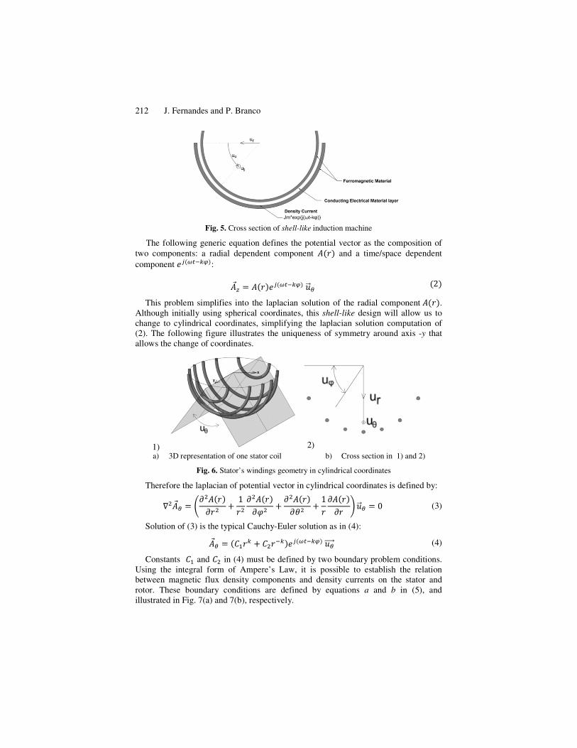
Figure 5 shows a schematic for the analytical model, which was formulated under the
following assumptions: one single homogeneous zone (airgap); a thin current density
layer defined as the inner stator surface; a thin electric conducting material layer (� –
electrical conductivity) defined as the outer surface of the rotor; a high permeability
ferromagnetic material on the stator and also in the rotor; and negligence of border
effects due to the small size of the airgap in relation to the stator length.
To produce an electromagnetic torque it is needed the presence of a travelling
wave of electromotive force (EMF) in the rotor. This will be originated by the airgap
travelling magnetic wave due to the current density circulating in the stator. The EMF
wave is an image of the stator current density being expressed by (1), where k is the
wavelength of the stator’s EMF (equivalent to the number of poles of the stator):
��� � ������� ��������� (1)
As result the airgap potential vector will be similar to the current density.
212 J. Fernandes and P. Branco
Fig. 5. Cross section of shell-like induction machine
The following generic equation defines the potential vector as the composition of
two components: a radial dependent component ���� and a time/space dependent
component ��� ����: ��� � ������� �������� �2�
This problem simplifies into the laplacian solution of the radial component����. Although initially using spherical coordinates, this shell-like design will allow us to
change to cylindrical coordinates, simplifying the laplacian solution computation of
(2). The following figure illustrates the uniqueness of symmetry around axis -y that
allows the change of coordinates.
a) 3D representation of one stator coil b) Cross section in 1) and 2)
Fig. 6. Stator’s windings geometry in cylindrical coordinates
Therefore the laplacian of potential vector in cylindrical coordinates is defined by:
����� � ���������� � 1��
�������!� � ������
�"� � 1�������� #���� � 0
(3)
Solution of (3) is the typical Cauchy-Euler solution as in (4):
��� � �%&�� � %�������� ����������� (4)
Constants %& and %� in (4) must be defined by two boundary problem conditions.
Using the integral form of Ampere’s Law, it is possible to establish the relation
between magnetic flux density components and density currents on the stator and
rotor. These boundary conditions are defined by equations a and b in (5), and
illustrated in Fig. 7(a) and 7(b), respectively.
1) 2)

A Shell-Like Induction Electrical Machine 213
a) b)
Fig. 7. Boundary condition – Ampere’s law in the a) stator and b) rotor.
'�( )*+
,- � ( �./0
1��,!, 3�( )�,!/0
� ( �4/0
1��,! (5)
The stator current density ��� is the source for the rotor EMF, resulting in the rotor
induced density current ��4 , given by (6), taking in account the electric field 5�� and the
linear tangential velocity of the rotor, 6��. ��4 � �75�� � 6�� × 9��: � � �−�����< − =>
�����! # (6)
Defining the slip parameter ? � �@ − A@B�,constants CD and CE become given by
(7) and (8). Term BB is the radius of the rotor, BF is the radius of the stator.
%& � �GHIJ���K&LM1 � N IJ�OL �>P
�−�>�� � ���� � N IJ�OL ��>�� � �����#
(7)
%� � �GHIJ���K&�>��LM1 − N IJ�OL �>P
�−�>�� � ���� � N IJ�OL ��>�� � �����# (8)
4.1 Electromechanical Characteristics
The magnetic flux density is given by the rotational of the potential vector eq. (9).
As result, the magnetic flux density presents two components, 9��> and 9���, and the
induced current only one component, ���.
9�� � � × ��� , 9�� � �1������! #���> � �−������ # ����
9��> � −N L� �%&�� � %�������� �������>
9��� � −L� �%&�� − %�������� ��������
(9)
(10)
(11)

214 J. Fernandes and P. Branco
��4 � � �−�����< − =>�����! # � −N�O�%&�>� � %��>������ ��*�� (12)
With the magnetic flux density given by (10) and (11) and the induced current
density from (12), the magnetic force density in the rotor is computed as in (13). This
shows the resultant force density having two components, a radial Q�> and a tangential
one Q��.
Q� � ��4 × 9�� � Q�> � Q�� (13)
For motion applications, it is important to analyze the resultant average force
density in the rotor and thus the average torque. This can be obtained as shown in (14)
taking in account the active surface area of the rotor, its radius and the average force
density in (15).
⟨S�⟩ � �> U⟨Q�⟩ ,",!, ⟨S>⟩ � �> U⟨Q>⟩ ,",! (14)
⟨Q�⟩ � 12����V49W>
∗�, ⟨Q>⟩ � 12����V49W�
∗� (15)
4.2 Parameters’ Sensibility
Figures 8 (a) and (b) show the dependence of the tangential and radial force density
in the rotor in function of parameter k, which is the wavelength of stator’s EMF.
These results were obtained for a 5cm rotor radius with a 2mm thick aluminum
material, a 2mm airgap and a stator current density of 6 × 10Z�/\� (typical value of
current density in electrical machines).
Results show that when increasing the wavelength of EMF (parameter k), both
density forces magnitude are reduced, moving the maximum tangential density force
to higher values of slip O]. The radial component presents a repulsing force between
stator and rotor.
a) b)
Fig. 8. Influence of the EMF’s wavelength in the density force components on rotor: (a)
tangential component; (b) radial component. O′ � �= − L=>� ω⁄ .
Figures 9(a) and 9(b) indicate that the change of the rotor’s electric conductivity
has a similar effect as in classic induction machines. The maximum point of the force
will be shifted to higher values of synchronism when decreasing the conductivity.

A Shell-Like Induction Electrical Machine 215
a) b)
Fig. 9. Influence of electric conductivity’s material of the rotor in the density force
components: (a) tangential component; (b) radial component. O′ � �= − L=>� ω⁄ .
5 Assistive Device Application
In this section it is analyzed the application of the shell-like actuator as an active joint
for assistive devices. Application is a device for assistive movement of the lower leg
for a typical 70kg person, usually used in orthopedics. Table 1 resumes the
specifications of the active joint. For this purpose, the shell-like induction motor will
have a simple design with a stator shell covering half of the rotor. This design
warranties the range of motion in both Sagittal and Coronal planes.
Table 1. Specifications for the orthopedic active joint.
Total weight to lift with a 0.25m
distance to the center of mass
2 kg (average lower leg
for 70 kg person)
Average linear velocity 3 Km/h [0,83m/s]
Range of Motion for Sagittal plane [-10° 90°] Range of Motion for Coronal plane [-25° 25°] Rated torque 5 Nm
Range of radius [2,5 5] cm
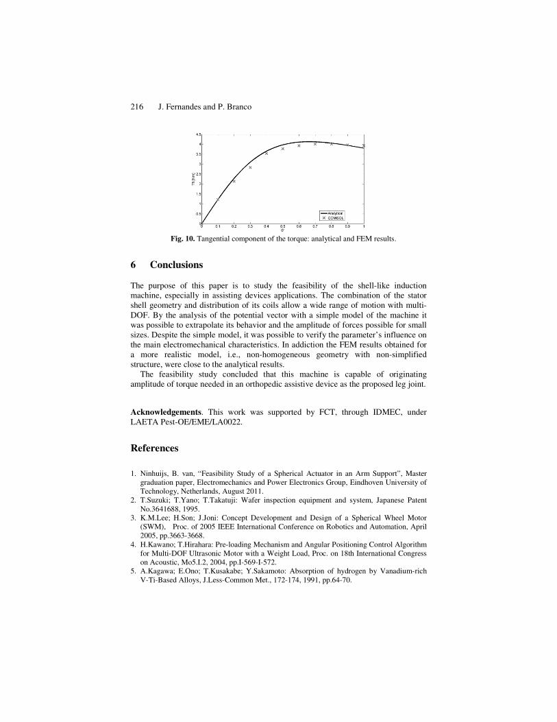
To study its feasibility, it was considered a 5cm radius rotor with a 2mm thick
aluminum conducting material, a 2mm thick airgap, a 50 Hz stator current density of 6 × 10ZA/m� and k=4. For comparison, our design was simulated in 2D finite
element method (FEM) program. FEM results are compared with the analytical
solutions. For example, Figure 10 plots the resultant average torque obtained from the
analytical model (continuous line) and that one determined using the FEM model
(discrete marks).
The maximum torque obtained is about 4 Nm, therefore near to the specified one.
The maximum angular velocity corresponds to 3.9m/s (78.5 rad/s�, including the
average linear velocity of 0.83m/s (16.6 rad/s). This preliminary analysis indicates
that the shell-like actuator design is capable of be the joint of the orthopedics assistive
device.
216 J. Fernandes and P. Branco
Fig. 10. Tangential component of the torque: analytical and FEM results.
6 Conclusions
The purpose of this paper is to study the feasibility of the shell-like induction
machine, especially in assisting devices applications. The combination of the stator
shell geometry and distribution of its coils allow a wide range of motion with multi-
DOF. By the analysis of the potential vector with a simple model of the machine it
was possible to extrapolate its behavior and the amplitude of forces possible for small
sizes. Despite the simple model, it was possible to verify the parameter’s influence on
the main electromechanical characteristics. In addiction the FEM results obtained for
a more realistic model, i.e., non-homogeneous geometry with non-simplified
structure, were close to the analytical results.
The feasibility study concluded that this machine is capable of originating
amplitude of torque needed in an orthopedic assistive device as the proposed leg joint.
Acknowledgements. This work was supported by FCT, through IDMEC, under
LAETA Pest-OE/EME/LA0022.
References
1. Ninhuijs, B. van, “Feasibility Study of a Spherical Actuator in an Arm Support”, Master
graduation paper, Electromechanics and Power Electronics Group, Eindhoven University of
Technology, Netherlands, August 2011.
2. T.Suzuki; T.Yano; T.Takatuji: Wafer inspection equipment and system, Japanese Patent
No.3641688, 1995.
3. K.M.Lee; H.Son; J.Joni: Concept Development and Design of a Spherical Wheel Motor
(SWM), Proc. of 2005 IEEE International Conference on Robotics and Automation, April
2005, pp.3663-3668.
4. H.Kawano; T.Hirahara: Pre-loading Mechanism and Angular Positioning Control Algorithm
for Multi-DOF Ultrasonic Motor with a Weight Load, Proc. on 18th International Congress
on Acoustic, Mo5.I.2, 2004, pp.I-569-I-572.
5. A.Kagawa; E.Ono; T.Kusakabe; Y.Sakamoto: Absorption of hydrogen by Vanadium-rich
V-Ti-Based Alloys, J.Less-Common Met., 172-174, 1991, pp.64-70.