Embed Size (px)
DESCRIPTION
A silicon microdosimeter for radiation quality assessment. S. AGOSTEO (1,2) , C.A. CASSELL (2,3,4) , A. FAZZI (1,2) , ) M.V. INTROINI (1,2) , M. LORENZOLI (1,2) , A. POLA (1,2) , E. SAGIA (2,3) , V. VAROLI (1,2). (1) INFN, Sezione di Milano, via Celoria 16, 20133 Milano, Italy. - PowerPoint PPT Presentation
Citation preview
A silicon microdosimeter for A silicon microdosimeter for radiation quality assessmentradiation quality assessment
(1) INFN, Sezione di Milano, via Celoria 16, 20133 Milano, Italy.(2) Politecnico di Milano, Dipartimento di Energia, Sezione di Ingegneria Nucleare CeSNEF, via Ponzio 34/3, 20133 Milano, Italy.(3) ARDENT framework.(4) Centre for medical radiation physics, UOW.
S. AGOSTEO (1,2), C.A. CASSELL(2,3,4), A. FAZZI (1,2),) M.V. INTROINI (1,2), M. LORENZOLI (1,2),
A. POLA (1,2), E. SAGIA(2,3), V. VAROLI (1,2).
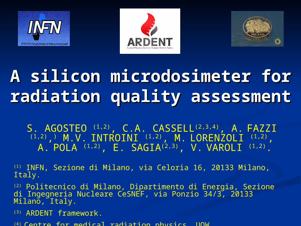
SOLID STATE MICRODOSIMETERSSOLID STATE MICRODOSIMETERS
Si-devices can provide sensitive zones of the order of a micrometer
CHALLENGING DEVICES FOR MICRODOSIMETRY
SpectroscopyChain
Data Analysis
Silicon device
Tissue-equivalent converter
Spectrum of the energy imparted
per event in siliconMicrodosimetric
spectrum in tissue
Analytical corrections
HOW a Si-DEVICE BASED MICRODOSIMETER WORKS?…HOW a Si-DEVICE BASED MICRODOSIMETER WORKS?…
PN diodes in SOI wafer
[1] B. Rosenfeld, P. Bradley, I. Cornelius, G. Kaplan, B. Allen, J. Flanz, M. Goitein, A.V. Meerbeeck, J. Schubert, J. Bailey, Y. Tabkada, A. Maruashi, Y. Hayakawa, New silicon detector for microdosimetry applications in proton therapy, IEEE Trans. Nucl. Sci. 47(4) (2000) 1386-1394.
[2] P. Bradley, A.B. Rosenfeld, B.J. Allen, J. Coderre, and J. Capala, Performance of silicon microdosimetry detectors in boron neutron capture therapy, Radiation Research 151 (1999) 235-243.
[3] P.D. Bradley, The Development of a Novel Silicon Microdosimeter for High LET Radiation Therapy , Ph. D. Thesis, Department of Engineering Physics, University of Wollongong, Wollongong, Australia (2000).
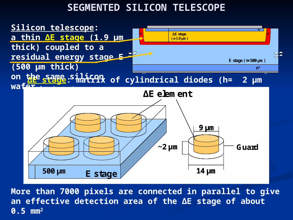
SEGMENTED SILICON TELESCOPESEGMENTED SILICON TELESCOPE
More than 7000 pixels are connected in parallel to give an effective detection area of the ∆E stage of about 0.5 mm2
∆E stage: matrix of cylindrical diodes (h= 2 µm , d= 9 μm)
500 µm 14 µm
9 µm
E stage
Guard~2 μm
∆E element
500 µm 14 µm
9 µm
E stage
Guard~2 μm
∆E element
n+
p+p+n+
E stage ( 500 μm)
ΔE stage ( 1.9 μm)
n+
p+p+n+
E stage ( 500 μm)
ΔE stage ( 1.9 μm)
Silicon telescope: a thin ∆E stage (1.9 μm thick) coupled to a residual energy stage E (500 μm thick)on the same silicon wafer.
MICRODOSIMETRIC SPECTRA: TISSUE-MICRODOSIMETRIC SPECTRA: TISSUE-EQUIVALENCEEQUIVALENCE
AND GEOMETRICAL CORRECTIONSAND GEOMETRICAL CORRECTIONSIn order to derive microdosimetric spectra similar to those acquired by a TEPC, corrections were studied and discussed in details [1,2]
The telescope allows to optimize the tissue equivalence correction by measuring event-by-event the energy of the impinging particles and by discriminating them.
Tissue equivalence of silicon
Shape equivalence
By following a parametric criteria given in literature, the lineal energy y was calculated by considering an equivalent mean cord length.
1. S. Agosteo, P. Colautti, A. Fazzi, D. Moro and A. Pola, “A Solid State Microdosimeter based on a Monolithic Silicon Telescope”, Radiat. Prot. Dosim. 122, 382-386 (2006).
2. S. Agosteo, P.G. Fallica, A. Fazzi, M.V. Introini, A. Pola, G. Valvo, “A Pixelated Silicon Telescope for Solid State Microdosimeter”, Radiat. Meas., accepted for publication.
TISSUE EQUIVALENCE TISSUE EQUIVALENCE CORRECTIONCORRECTION
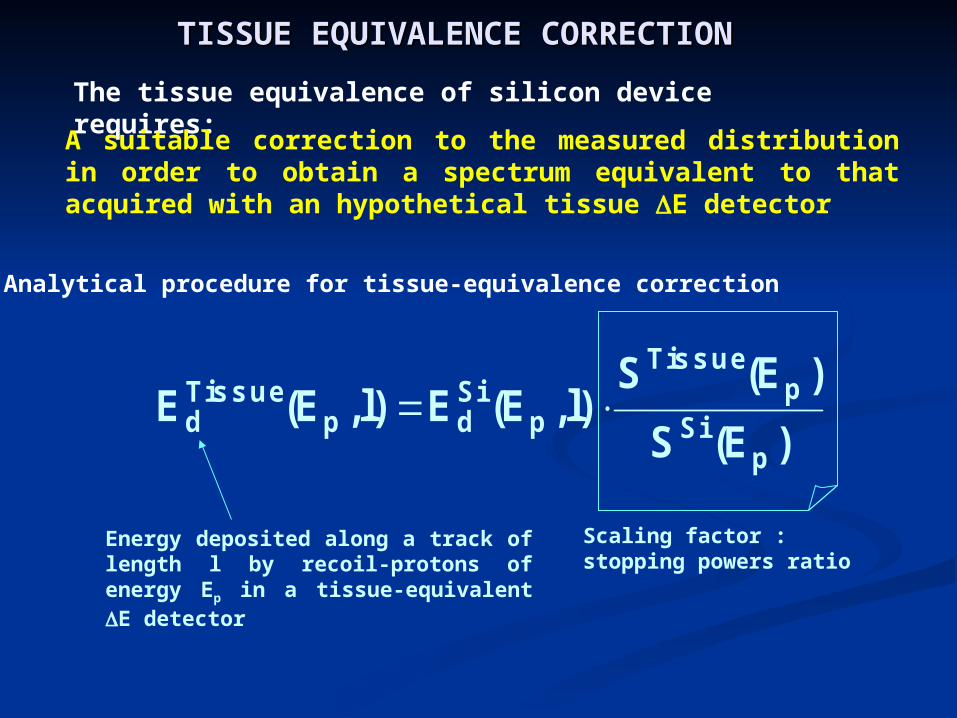
The tissue equivalence of silicon device requires:
A suitable correction to the measured distribution in order to obtain a spectrum equivalent to that acquired with an hypothetical tissue E detector
Analytical procedure for tissue-equivalence correction
Energy deposited along a track of length l by recoil-protons of energy Ep in a tissue-equivalent E detector
)E(S
)E(S)l,E(E)l,E(E
pSi
pTis s ue
pSidp
Tis s ued
Scaling factor : stopping powers ratio
TISSUE-EQUIVALENCE CORRECTIONTISSUE-EQUIVALENCE CORRECTION
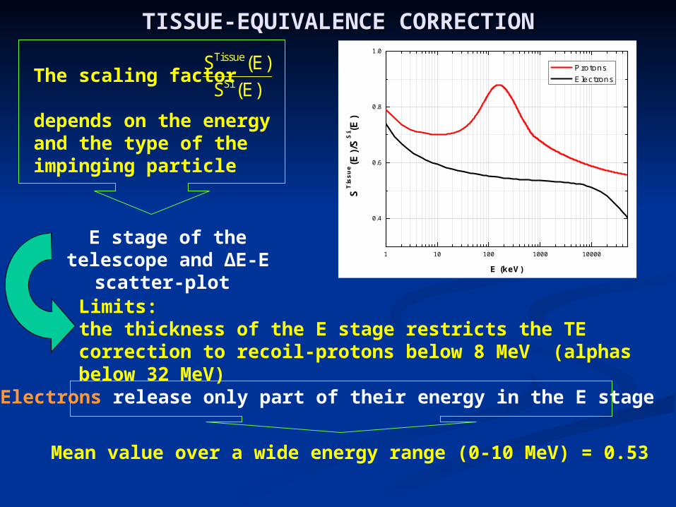
The scaling factor
depends on the energy and the type of the impinging particle
)E(S
)E(SSi
Tissue
E stage of the telescope and ∆E-E scatter-plot 1 10 100 1000 10000
0.4
0.6
0.8
1.0
ST
issu
e (E)/
SS
i (E)
E (keV)
Protons Electrons
Mean value over a wide energy range (0-10 MeV) = 0.53
Electrons release only part of their energy in the E stage
Limits:the thickness of the E stage restricts the TE correction to recoil-protons below 8 MeV (alphas below 32 MeV)
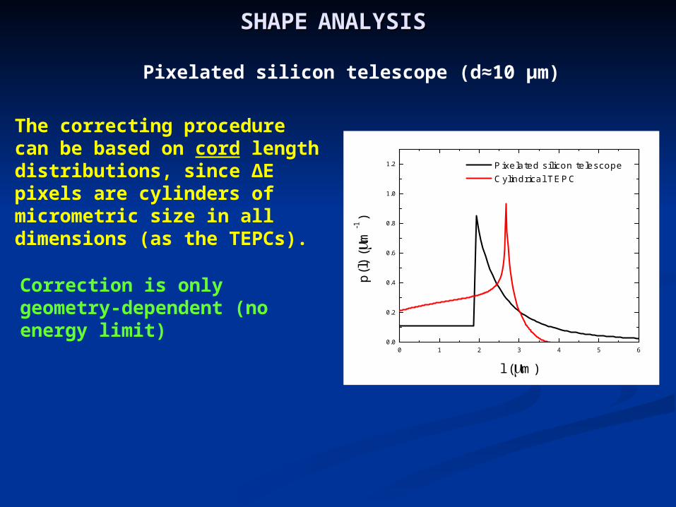
SHAPESHAPE ANALYSISANALYSIS
Pixelated silicon telescope (d≈10 μm)
The correcting procedure can be based on cord length distributions, since ∆E pixels are cylinders of micrometric size in all dimensions (as the TEPCs).
Correction is only geometry-dependent (no energy limit)
0 1 2 3 4 5 60.0
0.2
0.4
0.6
0.8
1.0
1.2
p(l)
(m
-1)
l (m)
Pixelated silicon telescope Cylindrical TEPC
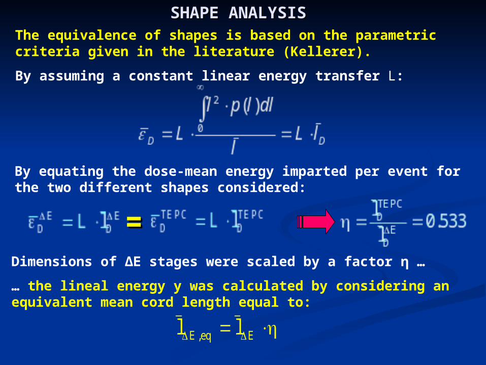
SHAPE ANALYSIS SHAPE ANALYSIS The equivalence of shapes is based on the parametric criteria given in the literature (Kellerer).
By assuming a constant linear energy transfer L:
By equating the dose-mean energy imparted per event for the two different shapes considered:
==
Eeq,E ll
Dimensions of ∆E stages were scaled by a factor η …
… the lineal energy y was calculated by considering an equivalent mean cord length equal to:
RESPONSE TO PROTONS:RESPONSE TO PROTONS:
Irradiations withIrradiations with62 MeV modulated proton 62 MeV modulated proton
beambeamat CATANA facilityat CATANA facility
(LNS-INFN Catania)(LNS-INFN Catania)andand
comparison with cylindrical comparison with cylindrical TEPC TEPC
(De Nardo et al., RPD 110, 1-(De Nardo et al., RPD 110, 1-4 (2004) 4 (2004)
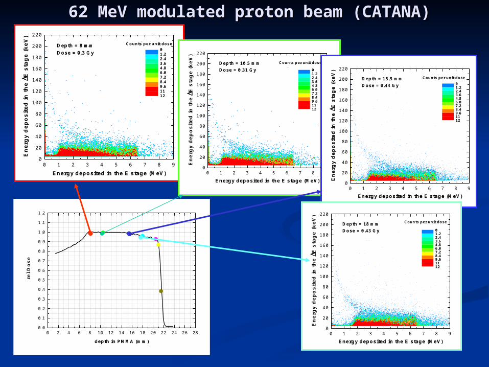
62 MeV modulated proton beam (CATANA)62 MeV modulated proton beam (CATANA)
0 2 4 6 8 10 12 14 16 18 20 22 24 26 280.0
0.1
0.2
0.3
0.4
0.5
0.6
0.7
0.8
0.9
1.0
1.1
1.2
rel D
os
e
depth in PMMA (mm)
0 1 2 3 4 5 6 7 8 90
20
40
60
80
100
120
140
160
180
200
220
Counts per unit doseDepth = 8 mmDose = 0.3 Gy
En
erg
y d
epo
site
d i
n t
he E
sta
ge
(keV
)
Energy deposited in the E stage (MeV)
01.22.43.64.86.07.28.49.61112
0 1 2 3 4 5 6 7 8 90
20
40
60
80
100
120
140
160
180
200
220
Depth = 10.5 mmDose = 0.31 Gy
En
erg
y d
epo
site
d i
n t
he E
sta
ge
(keV
)
Energy deposited in the E stage (MeV)
Counts per unit dose
01.22.43.64.86.07.28.49.61112
0 1 2 3 4 5 6 7 8 90
20
40
60
80
100
120
140
160
180
200
220
Counts per unit doseDepth = 15.5 mmDose = 0.44 Gy
En
erg
y d
epo
site
d i
n t
he E
sta
ge
(keV
)
Energy deposited in the E stage (MeV)
01.22.43.64.86.07.28.49.61112
0 1 2 3 4 5 6 7 8 90
20
40
60
80
100
120
140
160
180
200
220Counts per unit doseDepth = 18 mm
Dose = 0.43 Gy
En
erg
y d
epo
site
d i
n t
he E
sta
ge
(keV
)
Energy deposited in the E stage (MeV)
01.22.43.64.86.07.28.49.61112

0 2 4 6 8 10 12 14 16 18 20 22 24 26 280.0
0.1
0.2
0.3
0.4
0.5
0.6
0.7
0.8
0.9
1.0
1.1
1.2
rel D
os
e
depth in PMMA (mm)
62 MeV modulated proton beam (CATANA)62 MeV modulated proton beam (CATANA)
0 1 2 3 4 5 6 7 8 90
20
40
60
80
100
120
140
160
180
200
220Counts per unit doseDepth = 20.5 mm
Dose = 0.36 Gy
En
erg
y d
epo
site
d i
n t
he E
sta
ge
(keV
)
Energy deposited in the E stage (MeV)
00.701.42.12.83.54.24.95.66.37.0
0 1 2 3 4 5 6 7 8 90
20
40
60
80
100
120
140
160
180
200
220
Counts per unit doseDepth = 21 mmDose = 0.46 Gy
En
erg
y d
epo
site
d i
n t
he E
sta
ge
(keV
)
Energy deposited in the E stage (MeV)
00.701.42.12.83.54.24.95.66.37.0
0 1 2 3 4 5 6 7 8 90
20
40
60
80
100
120
140
160
180
200
220
Counts per unit doseDepth = 21.5 mmDose = 0.62 Gy
En
erg
y d
epo
site
d i
n t
he E
sta
ge
(keV
)
Energy deposited in the E stage (MeV)
00.701.42.12.83.54.24.95.66.37.0
0 2 4 6 8 10 12 14 16 18 20 22 240.0
0.5
1.0
1.5
2.0
2.5
3.0
3.5
4.0
4.5
5.0
Dep
th d
ose
curv
e (a
.u.)
depth in PMMA (mm)
0.1 1 10 100 10000.0
0.2
0.4
0.6
0.8
1.0
1.2
1.4
1.6
1.8
2.0
2.2
2.4
2.6
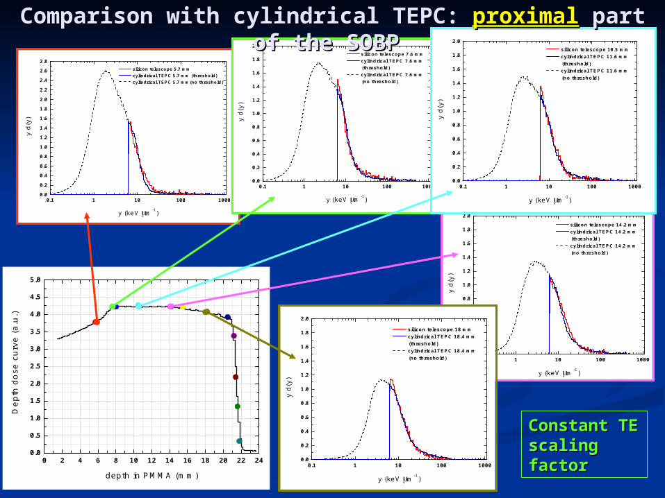
2.8 silicon telescope 5.7 mm cylindrical TEPC 5.7 mm (threshold) cylindrical TEPC 5.7 mm(no threshold)
y d(
y)
y (keV m-1)
0.1 1 10 100 10000.0
0.2
0.4
0.6
0.8
1.0
1.2
1.4
1.6
1.8
2.0 silicon telescope 7.6 mm cylindrical TEPC 7.6 mm
(threshold) cylindrical TEPC 7.6 mm
(no threshold)
y d(
y)
y (keV m-1)
0.1 1 10 100 10000.0
0.2
0.4
0.6
0.8
1.0
1.2
1.4
1.6
1.8
2.0
silicon telescope 14.2 mm cylindrical TEPC 14.2 mm
(threshold) cylindrical TEPC 14.2 mm
(no threshold)
y d(
y)
y (keV m-1)
0.1 1 10 100 10000.0
0.2
0.4
0.6
0.8
1.0
1.2
1.4
1.6
1.8
2.0 silicon telescope 10.5 mm cylindrical TEPC 11.6 mm
(threshold) cylindrical TEPC 11.6 mm
(no threshold)
y d(
y)
y (keV m-1)
0.1 1 10 100 10000.0
0.2
0.4
0.6
0.8
1.0
1.2
1.4
1.6
1.8
2.0
silicon telescope 18 mm cylindrical TEPC 18.4 mm
(threshold) cylindrical TEPC 18.4 mm
(no threshold)
y d(
y)
y (keV m-1)
Constant TE Constant TE scaling factorscaling factor
Comparison with cylindrical TEPC: Comparison with cylindrical TEPC: proximalproximal part of part of the SOBP the SOBP

0 2 4 6 8 10 12 14 16 18 20 22 240.0
0.5
1.0
1.5
2.0
2.5
3.0
3.5
4.0
4.5
5.0
Dep
th d
ose
curv
e (a
.u.)
depth in PMMA (mm)
1 10 100 10000.0
0.2
0.4
0.6
0.8
1.0
silicon telescope 20.5 mm cylindrical TEPC 20.1 mm
(threshold) cylindrical TEPC 20.1 mm
(no threshold)
y d(
y)
y (keV m-1)
1 10 100 10000.0
0.2
0.4
0.6
0.8
1.0
silicon telescope 21.2 mm cylindrical TEPC 21.4 mm
(threshold) cylindrical TEPC 21.4 mm
(no threshold)
y d(
y)y (keV m-1)
1 10 100 10000.0
0.2
0.4
0.6
0.8
1.0
silicon telescope 21.4 mm cylindrical TEPC 21.6 mm
(threshold) cylindrical TEPC 21.6 mm
(no threshold)
y d(
y)
y (keV m-1)
1 10 100 10000.0
0.2
0.4
0.6
0.8
1.0
silicon telescope 21.6 mm cylindrical TEPC 21.8 mm
(threshold) cylindrical TEPC 21.8 mm
(no threshold)
y d(
y)
y (keV m-1)
1 10 100 10000.0
0.2
0.4
0.6
0.8
1.0
silicon telescope 21.8 mm cylindrical TEPC 22 mm
(threshold) cylindrical TEPC 22 mm
(no threshold)
y d(
y)
y (keV m-1)
Event-by-event Event-by-event TE correctionTE correction
Comparison with cylindrical TEPC: Comparison with cylindrical TEPC: distaldistal part of the part of the SOBP SOBP
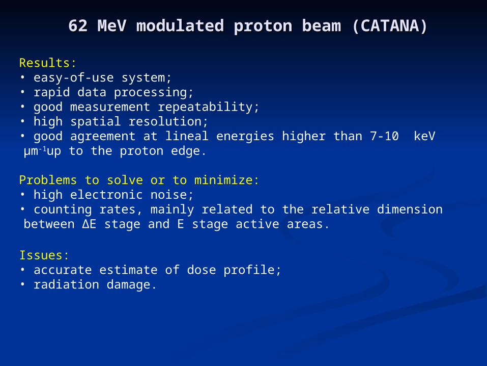
Results:• easy-of-use system;• rapid data processing;• good measurement repeatability;• high spatial resolution;• good agreement at lineal energies higher than 7-10 keV μm-1up to the proton edge.
Problems to solve or to minimize:• high electronic noise;• counting rates, mainly related to the relative dimension between ∆E stage and E stage active areas.
Issues:• accurate estimate of dose profile;• radiation damage.
62 MeV modulated proton beam (CATANA)62 MeV modulated proton beam (CATANA)
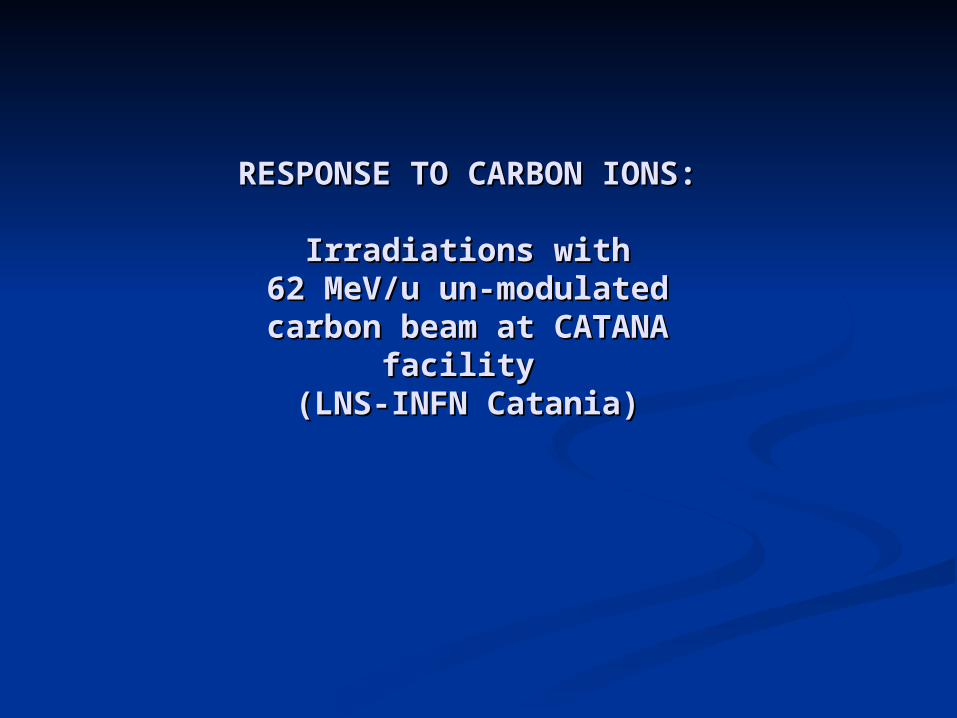
RESPONSE TO CARBON RESPONSE TO CARBON IONS:IONS:
Irradiations withIrradiations with62 MeV/u un-modulated 62 MeV/u un-modulated carbon beam at CATANA carbon beam at CATANA
facility facility (LNS-INFN Catania)(LNS-INFN Catania)
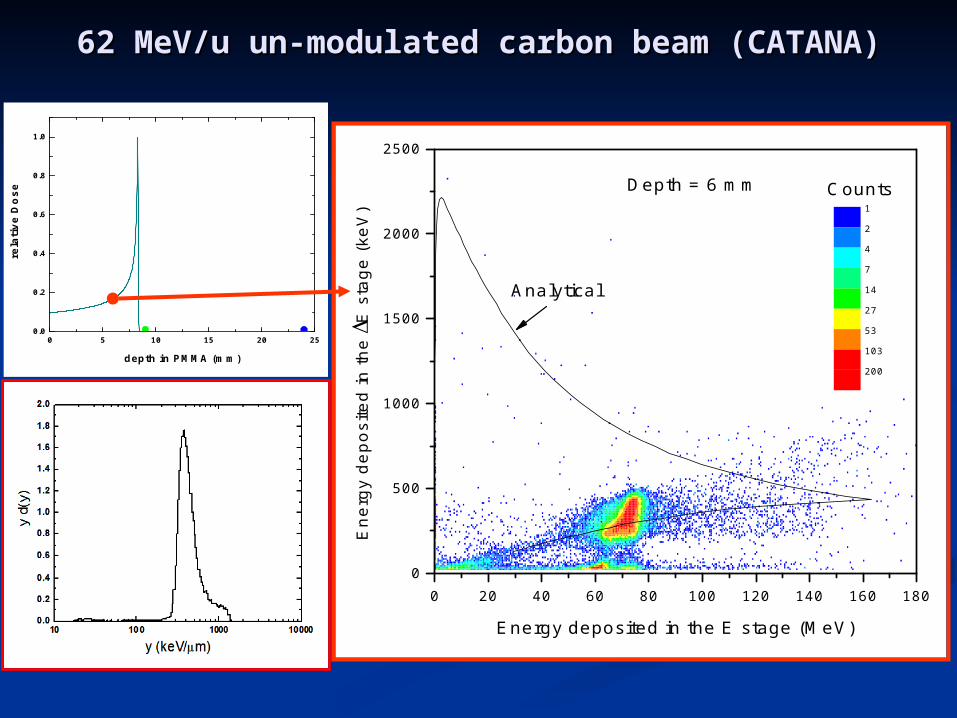
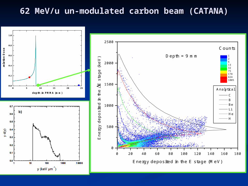
62 MeV/u un-modulated carbon beam (CATANA)62 MeV/u un-modulated carbon beam (CATANA)
0 5 10 15 20 250.0
0.2
0.4
0.6
0.8
1.0
rela
tive
Do
se
depth in PMMA (mm)
0 20 40 60 80 100 120 140 160 1800
500
1000
1500
2000
2500
Analytical
Energy deposited in the E stage (MeV)
Ene
rgy
depo
site
d in
the E
sta
ge (
keV
) 1
2
4
7
14
27
53
103
200
Depth = 6 mm Counts
0 5 10 15 20 250.0
0.2
0.4
0.6
0.8
1.0
rela
tive
Do
se
depth in PMMA (mm)
0 20 40 60 80 100 120 140 160 1800
500
1000
1500
2000
2500
C B Be Li He H
Energy deposited in the E stage (MeV)
En
ergy
dep
osite
d in
the E
sta
ge
(keV
) 1261332751784241005
Depth = 9 mm
Counts
Analytical
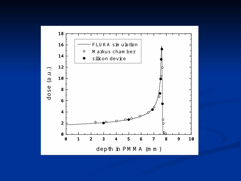
62 MeV/u un-modulated carbon beam (CATANA)62 MeV/u un-modulated carbon beam (CATANA)
0 1 2 3 4 5 6 7 8 9 100
2
4
6
8
10
12
14
16
18
FLUKA simulation Markus chamber silicon device
dose
(a.
u.)
depth in PMMA (mm)
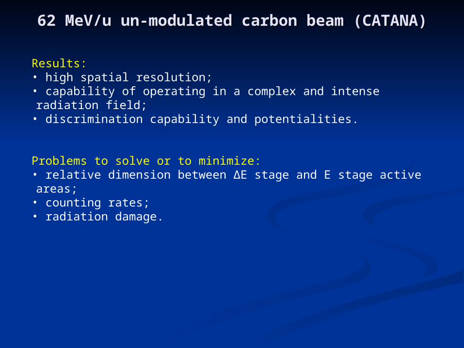
Results:• high spatial resolution;• capability of operating in a complex and intense radiation field;• discrimination capability and potentialities.
Problems to solve or to minimize:• relative dimension between ∆E stage and E stage active areas;• counting rates;• radiation damage.
62 MeV/u un-modulated carbon beam (CATANA)62 MeV/u un-modulated carbon beam (CATANA)
CONCLUSIONSCONCLUSIONS
IMPROVEMENT OF THE IMPROVEMENT OF THE ENERGY TRESHOLD:ENERGY TRESHOLD:
A feasibility study of a low-A feasibility study of a low-LET silicon microdosimeterLET silicon microdosimeter
Improvement of the energy thresholdImprovement of the energy threshold
The main limitation of the system is the high energy threshold imposed by the electronic noise.
New design of the segmented telescope with a ∆E stage having a lower number of cylinders connected in parallel and an E stage with an optimized sensitive area
1. Decrease the energy threshold below 1 keV μm-1
2. Optimize the counting rate of the two stages