Embed Size (px)
Citation preview

A simpleand efficient rectification method for generalmotion
MarcPollefeys,ReinhardKoch�
andLuc VanGoolESAT-PSI,K.U.Leuven
KardinaalMercierlaan94B-3001Heverlee,Belgium
Abstract
In thispapera new rectificationmethodis proposed.Themethodis both simpleand efficient and can deal with allpossiblecamera motions.A minimalimagesizewithoutanypixel lossis guaranteed.Theonly required informationisthe orientedfundamentalmatrix. The whole rectificationprocessis carriedout directlyin theimages.Theideacon-sistsof usinga polar parametrizationof the image aroundthe epipole. The transferbetweenthe images is obtainedthroughthefundamentalmatrix. Theproposedmethodhasimportantadvantagescomparedto thetraditional rectifica-tion schemes. In somecasestheseapproachesyield verylargeimagesor cannotrectifyat all. Eventherecentlypro-posedcylindrical rectificationmethodcanencounterprob-lems in somecases. Theseproblemsare mainly due tothe fact that thematching ambiguityis not reducedto halfepipolar lines. Althoughthis last methodis more complexthantheoneproposedin thispapertheresultingimagesarein general larger. Theperformanceof thenew approach isillustratedwith someresultson real imagepairs.
1. Intr oduction
Thestereomatchingproblemcanbesolvedmuchmoreefficiently if imagesarerectified.Thisstepconsistsof trans-forming the imagesso that the epipolarlines are alignedhorizontally. In this casestereomatchingalgorithmscaneasilytake advantageof theepipolarconstraintandreducethesearchspaceto onedimension(i.e. correspondingrowsof therectifiedimages).
The traditional rectification schemeconsistsof trans-forming the imageplanesso that the correspondingspaceplanesare coinciding [1]. There exist many variantsofthis traditionalapproach(e.g. [1, 5, 13]), it waseven im-
1Now at the Multimedia InformationProcessing,Inst. for ComputerScience,Universitat Kiel, Germany
plementedin hardware[2]. This approachfails whentheepipolesarelocatedin the imagessincethis would have toresultsin infinitely largeimages.Evenwhenthis is not thecasetheimagecanstill becomeverylarge(i.e. if theepipoleis closeto theimage).
A recentapproachby Roy, MeunierandCox[15] avoidsmostof the problemsof existing rectificationapproaches.This methodproposesto rectify on a cylinder in steadofa plane. It hastwo important features: it can deal withepipoleslocatedin theimagesandit doesnotcompressanypartof the image. Themethodis however relatively com-plex sinceall operationsare performedin 3-dimensionalspace.Everyepipolarline is consecutively transformed,ro-tatedandscaled. Although the methodcanwork withoutcalibrationit still assumesorientedcameras. This is notguaranteedfor a weakly calibratedimagepair. The maindisadvantageof this methodis that it doesnot take advan-tageof thefactthatthematchingambiguityin stereomatch-ing is reducedto half epipolarlines. With the epipolesintheimagesthis leadsto anunnecessarycomputationalover-head.For somecasesthis couldevenleadto thefailureofstereoalgorithmsthat enforcethe orderingconstraint.Al-thoughthesizeof theimagesis alwaysfinite, it is not min-imal sincethediameterof thecylinder is determinedontheworstcasepixel for thewholeimage.
Here we presenta simple algorithm for rectificationwhich candealwith all possiblecamerageometries.Onlythe orientedfundamentalmatrix is required. All transfor-mationsaredonein theimages.Theimagesizeis assmallascanbeachievedwithoutcompressingpartsof theimages.This is achieved by preservingthe length of the epipolarlinesandby determiningthewidth independentlyfor everyhalf epipolarline.
For traditionalstereoapplicationsthelimitationsof stan-dardrectificationalgorithmsarenotsoimportant.Themaincomponentof cameradisplacementis parallelto theimagesfor classicalstereosetups.The limited vergencekeepstheepipolesfar from the images. New approachesin uncal-ibratedstructure-from-motion[14] however make it possi-

bleto retrieve3D modelsof scenesacquiredwith hand-heldcameras.In this caseforwardmotioncanno longerbeex-cluded.Especiallywhena streetor a similar kind of sceneis considered.
This paperis organizedasfollows. Section2 introducesthe conceptof epipolargeometryon which the methodisbased.Section3 describestheactualmethod.In Section4someexperimentson real imagesshow the resultsof ourapproach.Theconclusionsaregivenin Section5.
2. Epipolar geometry
Theepipolargeometrydescribestherelationsthatexistbetweentwo images. Every point in a planethat passesthroughbothcentersof projectionwill beprojectedin eachimageontheintersectionof thisplanewith thecorrespond-ing imageplane.Thereforethesetwo intersectionlinesaresaidto bein epipolarcorrespondence.
This geometrycan easily be recovered from the im-ages[11] even whenno calibrationis available[6, 7]. Ingeneral7 or more point matchesare sufficient. Robustmethodsto obtainthefundamentalmatrix from imagesaredescribedin [16, 18]. The epipolargeometryis describedby thefollowing equation:����������� (1)
where � and � � arehomogenousrepresentationsof corre-spondingimagepoints and � is the fundamentalmatrix.This matrix hasrank two, the right andleft nullspacecor-respondsto theepipoles and � which arecommonto allepipolarlines. Theepipolarline correspondingto a point �is thusgivenby � ��� ��� with � meaningequalityup to anon-zeroscalefactor(a strictly positive scalefactorwhenorientedgeometryis used,seefurther).
Epipolar line transfer The transfer of correspondingepipolarlinesis describedby thefollowing equations:
� � ����� � � or � ��� � � � (2)
with � ahomographyfor anarbitraryplane.As seenin [12]a valid homographycanimmediatelybeobtainedfrom thefundamentalmatrix:� �� ��������� ��� � (3)
with � a randomvectorfor which det�! "� so that � isinvertible.If onedisposesof cameraprojectionmatricesanalternativehomographyis easilyobtainedas:
��� � $#&%'� ��(*) % � (4)
where+ indicatestheMoore-Penrosepseudoinverse.
l4
l’4
3
1l2l
3
Π3
4Π
2
l’
l
1ΠΠ
1e’2l’
l’
e
Figure 1. Epipolar geometr y with the epipolesin the images. Note that the matc hing ambi-guity is reduced to half epipolar lines.
Orienting epipolar lines The epipolarlines canbe ori-entedsuchthat the matchingambiguityis reducedto halfepipolarlines insteadof full epipolarlines. This is impor-tantwhentheepipoleis in theimage.This factwasignoredin theapproachof Roy etal. [15].
Figure 1 illustratesthis concept. Pointslocatedin theright halvesof theepipolarplaneswill beprojectedon theright partof the imageplanesanddependingon theorien-tationof the imagein this planethis will correspondto theright or to theleft partof theepipolarlines.Theseconceptsareexplainedmorein detail in thework of Laveau[10] onorientedprojectivegeometry(seealso[8]).
In practicethis orientationcanbe obtainedas follows.Besidesthe epipolargeometryonepoint matchis needed(note that 7 or morematcheswereneededanyway to de-terminethe epipolargeometry).An orientedepipolarline� separatesthe imageplaneinto a positive anda negativeregion: ,.-./ ��0� � � � with �12� 354768� � (5)
Note that in this casethe ambiguityon � is restrictedto astrictly positive scalefactor. For a pair of matchingpoints/ �:9;� � 0 both
, - / ��0 and
, -=< / � � 0 shouldhave the samesign .Since � � is obtainedfrom � throughequation(2), this al-lows to determinethe sign of � . Oncethis sign hasbeendeterminedthe epipolarline transferis oriented. We taketheconventionthatthepositivesideof theepipolarline hasthepositiveregionof theimageto its right. This is clarifiedin Figure2.

+
---
m’
l’
le
+
+
+
+e’
++
m
-
-
-
-
+
-
Figure 2. Orientation of the epipolar lines.
3. GeneralizedRectification
Thekey ideaof ournew rectificationmethodconsistsofreparameterizingtheimagewith polarcoordinates(aroundthe epipoles).Sincethe ambiguitycanbe reducedto halfepipolarlinesonly positivelongitudinalcoordinateshavetobetakeninto account.Thecorrespondinghalf epipolarlinesaredeterminedthroughequation(2) takingorientationintoaccount.
Thefirst stepconsistsof determiningthecommonregionfor both images. Then, startingfrom one of the extremeepipolarlines,therectifiedimageis build up line by line. Iftheepipoleis in theimageanarbitraryepipolarline canbechosenasstartingpoint. In this caseboundaryeffectscanbe avoidedby addingan overlapof the sizeof the match-ing window of thestereoalgorithm(i.e. usemorethan360degrees).The distancebetweenconsecutive epipolarlinesis determinedindependentlyfor everyhalf epipolarlinessothatno pixel compressionoccurs.This non-linearwarpingallowsto obtaintheminimalachievableimagesizewithoutlosingimageinformation.
Thedifferentstepsof thismethodsaredescribedmoreindetailin thefollowing paragraphs.
Determining the common region Before determiningthe commonepipolarlines the extremalepipolarlines fora singleimageshouldbedetermined.Thesearetheepipo-lar lines that touchthe outer imagecorners.The differentregionsfor thepositionof theepipolearegivenin Figure3.Theextremalepipolarlinesalwayspassthroughcornersofthe image(e.g. if the epipole is in region 1 the areabe-tween ?> and A@ ). The extremeepipolar lines from thesecondimagecanbeobtainedthroughthesameprocedure.They shouldthenbetransferedto thefirst image.Thecom-monregion is theneasilydeterminedasin Figure4
Determining the distance between epipolar lines Toavoid losingpixel informationtheareaof everypixel shouldbeat leastpreservedwhentransformedto therectifiedim-age. The worst casepixel is always locatedon the imageborderoppositeto theepipole.A simpleprocedureto com-putethis stepis depictedin Figure5. Thesameprocedure
4 5
7
c
6
1 2 3
98
d
ba
Figure 3. the extreme epipolar lines can easil ybe determined depending on the location ofthe epipole in one of the 9 regions. The imagecorner s are given by ��9 > 9CBD9 @ .
l’
4
3
3l
l l’
1
2l
l
1
2
l’
l’
4
e’
e
Figure 4. Determination of the common re-gion. The extreme epipolar lines are used todetermine the maxim um angle .
l
l i-1
e=c
l
l
l1
n
l c’
i
i
b =b’i
i-1
a
a’
bi
Figure 5. Determining the minim um distancebetween two consecutive epipolar lines. Onthe left a whole image is sho wn, on the righta magnification of the area around point >FE isgiven. To avoid pix el loss the distance G � � B � Gshould be at least one pix el. This minimaldistance is easil y obtained by using the con-gruence of the triangles � > B and � � > � B � . Thenew point > is easil y obtained from the previ-ous by moving H IKJ8HH L�J8H pix els (down in this case).
x
y r
θ
r
rmax
θmax
min
θmin
θmaxrmax
θ
i
minminr
∆θi ∆θ
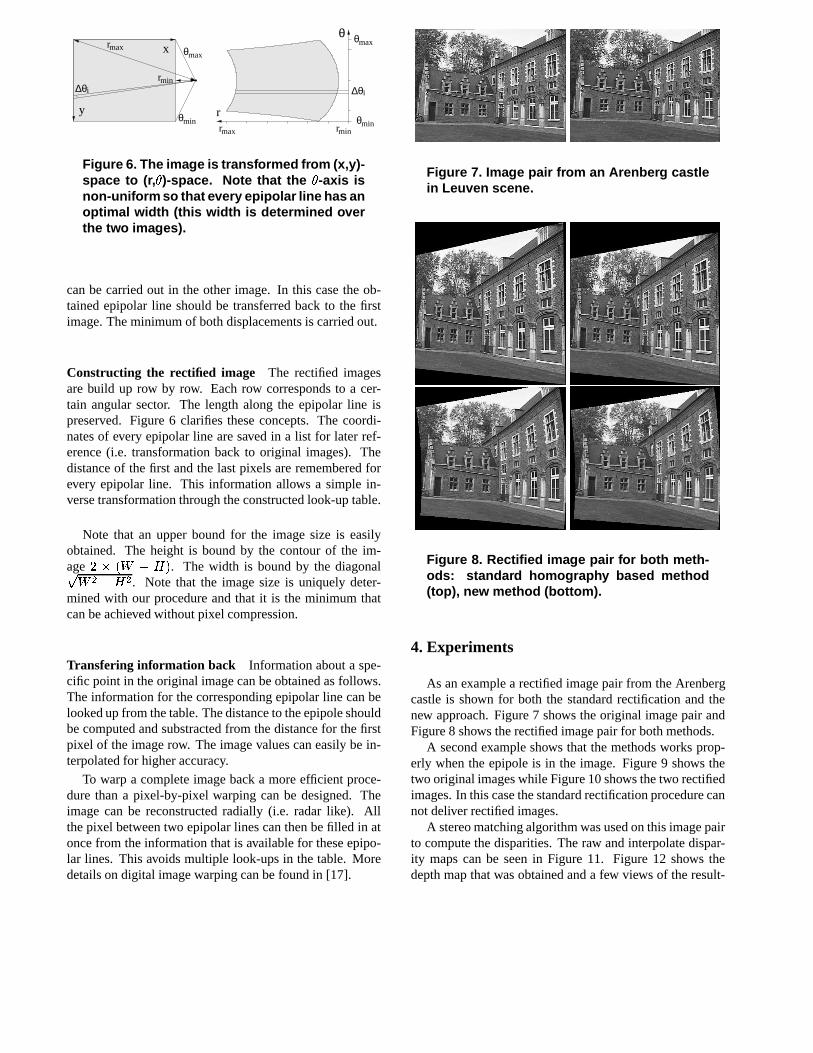
Figure 6. The image is transf ormed from (x,y)-space to (r, M )-space . Note that the M -axis isnon-unif orm so that every epipolar line has anoptimal width (this width is determined overthe two images).
canbe carriedout in the otherimage. In this casethe ob-tainedepipolarline shouldbe transferredback to the firstimage.Theminimumof bothdisplacementsis carriedout.
Constructing the rectified image The rectified imagesarebuild up row by row. Eachrow correspondsto a cer-tain angularsector. The length along the epipolarline ispreserved. Figure6 clarifiestheseconcepts.The coordi-natesof every epipolarline aresaved in a list for later ref-erence(i.e. transformationback to original images). Thedistanceof thefirst andthe lastpixelsarerememberedforevery epipolarline. This informationallows a simple in-versetransformationthroughtheconstructedlook-uptable.
Note that an upperboundfor the imagesize is easilyobtained. The height is boundby the contourof the im-age NPO /RQ �TSU0 . The width is boundby the diagonalV QTW �XS W . Note that the imagesize is uniquelydeter-minedwith our procedureandthat it is the minimum thatcanbeachievedwithoutpixel compression.
Transfering information back Informationabouta spe-cific point in theoriginal imagecanbeobtainedasfollows.Theinformationfor thecorrespondingepipolarline canbelookedupfrom thetable.Thedistanceto theepipoleshouldbecomputedandsubstractedfrom thedistancefor thefirstpixel of the imagerow. Theimagevaluescaneasilybe in-terpolatedfor higheraccuracy.
To warpa completeimagebacka moreefficient proce-dure thana pixel-by-pixel warpingcanbe designed.Theimagecan be reconstructedradially (i.e. radar like). Allthepixel betweentwo epipolarlinescanthenbefilled in atoncefrom theinformationthat is availablefor theseepipo-lar lines. This avoidsmultiple look-upsin the table. Moredetailsondigital imagewarpingcanbefoundin [17].
Figure 7. Image pair from an Arenber g castlein Leuven scene .
Figure 8. Rectified image pair for both meth-ods: standar d homograph y based method(top), new method (bottom).
4. Experiments
As anexamplea rectifiedimagepair from theArenbergcastleis shown for both the standardrectificationandthenew approach.Figure7 shows theoriginal imagepair andFigure8 showstherectifiedimagepair for bothmethods.
A secondexampleshows that themethodsworksprop-erly whenthe epipoleis in the image. Figure9 shows thetwo original imageswhile Figure10showsthetwo rectifiedimages.In thiscasethestandardrectificationprocedurecannotdeliver rectifiedimages.
A stereomatchingalgorithmwasusedonthis imagepairto computethedisparities.Theraw andinterpolatedispar-ity mapscan be seenin Figure 11. Figure 12 shows thedepthmapthatwasobtainedanda few views of theresult-

Figure 9. Image pair of the author s desk afew days before a deadline . The epipole isindicated by a white dot (top-right of ’Y’ in’VOLLEYBALL’).
ing 3D model are shown in Figure 13. Note from theseimagesthat thereis an importantdepthuncertaintyaroundtheepipole. In fact the epipoleforms a singularityfor thedepthestimation.In thedepthmapof Figure12 anartefactcanbeseenaroundthepositionof theepipole.Theextendis muchlongerin onespecificdirectiondueto the match-ing ambiguityin thisdirection(seetheoriginal imageor themiddle-rightpartof therectifiedimage).
5. Conclusion
In this paperwe have proposeda new rectificationalgo-rithm. Although the procedureis relatively simple it candeal with all possiblecamerageometries. In addition itguaranteesaminimal imagesize.Advantageis takenof thefactthatthematchingambiguityis reducedto half epipolarlines.Themethodwasimplementedandusedin thecontextof depthestimation.Thepossibilitiesof this new approachwere illustratedwith someresultsobtainedfrom real im-ages.
Acknowledgments
Wewishtoacknowledgethefinancialsupportof theBel-gian IUAP 24/02’ImechS’ projectandof theEU ESPRITltr. 20.243’IMPACT’ project.
References
[1] N. AyacheandC.Hansen,“Rectificationof imagesfor binoc-ular andtrinocularstereovision”, Proc. Intern. Conf. on Pat-ternRecognition, pp.11-16,1988.
[2] P. Courtney, N. ThackerandC. Brown, “A hardwarearchitec-ture for imagerectificationandgroundplaneobstacledetec-tion”, Proc. Intern.Conf. on PatternRecognition, pp. 23-26,1992.
[3] I. Cox, S. HingoraniandS. Rao, “A Maximum LikelihoodStereoAlgorithm”, ComputerVision andImage Understand-ing, Vol. 63,No. 3, May 1996.
Figure 10. Rectified pair of images of thedesk. It can be verified visuall y that corre-sponding points are located on correpondingimage rows. The right side of the images cor -responds to the epipole .
[4] L. Falkenhagen,“Hierarchical Block-BasedDisparity Esti-mation ConsideringNeighbourhoodConstraints”.Proc. In-ternational Workshopon SNHC and 3D Imaging, Rhodes,Greece,1997.
[5] O. Faugeras,Three-DimensionalComputerVision: a Geo-metricViewpoint, MIT press,1993.
[6] O. Faugeras,“What canbeseenin threedimensionswith anuncalibratedstereorig”, ComputerVision - ECCV’92, Lec-ture Notesin ComputerScience,Vol. 588, Springer-Verlag,pp.563-578,1992.
[7] R.Hartley, “Estimationof relativecamerapositionsfor uncal-ibratedcameras”,ComputerVision- ECCV’92, LectureNotesin ComputerScience,Vol. 588,Springer-Verlag,pp.579-587,1992.
[8] R. Hartley, “Cheirality invariants”, Proc. D.A.R.P.A. ImageUnderstandingWorkshop, pp.743-753,1993.
[9] R. Koch, Automatische OberflachenmodellierungstarrerdreidimensionalerObjekte aus stereoskopischen Rundum-Ansichten, PhD thesis, University of Hannover, Germany,1996alsopublishedasFortschritte-BerichteVDI, Reihe10,Nr.499,VDI Verlag,1997.
[10] S. LaveauandO. Faugeras,“OrientedProjective Geometryfor ComputerVision”, in : B. BuxtonandR. Cipolla (eds.),

Figure 11. Raw and interpolated disparity es-timates for the far image of the desk imagepair .
ComputerVision- ECCV’96, LectureNotesin ComputerSci-ence,Vol. 1064,Springer-Verlag,pp.147-156,1996.
[11] H. Longuet-Higgins,“A computeralgorithmfor reconstruct-ing a scenefrom two projections”, Nature, 293:133-135,1981.
[12] Q.-T. LuongandO.Faugeras,“The fundamentalmatrix: the-ory, algorithms,andstabilityanalysis”,InternationJournalofComputerVision, 17(1):43-76,1996.
[13] D. Papadimitriouand T. Dennis,“Epipolar line estimationandrectificationfor stereoimagepairs”, IEEE Trans.ImageProcessing, 5(4):672-676,1996.
[14] M. Pollefeys, R. Koch, M. Vergauwenand L. Van Gool,“Metric 3D SurfaceReconstructionfrom UncalibratedIm-age Sequences”,Proc. SMILE Workshop (post-ECCV’98),LectureNotesin ComputerScience,Vol. 1506,pp.138-153,Springer-Verlag,1998.
[15] S. Roy, J. MeunierandI. Cox, “Cylindrical RectificationtoMinimize Epipolar Distortion”, Proc. IEEE ConferenceonComputerVisionandPatternRecognition, pp.393-399,1997.
[16] P. Torr, Motion Segmentationand Outlier Detection, PhDThesis,Dept.of EngineeringScience,Universityof Oxford,1995.
[17] G.Wolberg,Digital ImageWarping, IEEEComputerSocietyPressMonograph,ISBN 0-8186-8944-7,1990.
[18] Z. Zhang,R. Deriche,O. FaugerasandQ.-T. Luong,“A ro-busttechniquefor matchingtwo uncalibratedimagesthroughthe recovery of the unknown epipolargeometry”,ArtificialIntelligenceJournal, Vol.78,pp.87-119,October1995.
Figure 12. Depth map for the far image of thedesk image pair .
Figure 13. Some views of the reconstructionobtained from the desk image pair . The inac-curac y at the top of the volle yball is due tothe depth ambiguity at the epipole .