Embed Size (px)
Citation preview

MINISTRY OF AVIATION
AERONAUTICAL RESEARCH COUNClL
CURRENT PAPERS
A Simple Method of Calculating the Flow Produced in an
Annular Electric Arc Heater by
1. M. Shaw
LONDON: HER MAJESTY’S SrATlONERY OFFICE
1965
PRICE 5s 6d NET


U.D.C. NO. 621.365.2 : 533.6.071 : 535.6.011.5
C.P. No.779 November i963
A SIMPLE METHOD OF CALCULATING THE FLOW PRODUCED IN AN ANNUDAR ELECTRIC ARC HRATER
J. id. Shaw
This note desoribes a simple model from which the flow in an annular eleotrio are heater can be calculated. It is intended to clarify ideas about such heaters, to direct thought to alternative possibly better types and to guide experimental work. When more experimental ‘and theoretical results are available it can form the basis from which heaters might be designed,
It is shown that the simple annular type of heater will probably produce excessive swirl in the outlet air stream. Alternatives are suggested.
Account is taken in the theory of both the heat addition and the forces produaed by the interaction of magnetic fields with the arc current.
-----ey-*-aDNe .-,__ *ma* .--em -^--*-a-. m-e-.--_- -
Replaocs R.A.E. Tech.Note No. Aoro.2922 - A.R.C. 25 692

CONTENTS
SYMBOLS
1 INTRODUCTION
2 FLOW MODEL
2.1 Determination of FS 2.2 Determination of FL
2.3 Determination of uarc 2.4 Determination of Q
3 MAGNITUDES OF QUAI'iTITIXS
3.1 Magnitude of Fe
3-Z Magnitude of FL 3.3 Magnitude of u
al-0 3.4 Magnitude of Q J-5 Magnitude of u2 3.6 Magnitude of ue
4 DISCUSSION OF RESULTS
4.1 Shortcomings of flow model 4-Z Practical interpretation
5 CONCLUSIONS
REFERENCES
APPENDIX1 - Consideration of the wake behind the arc
ILLUSTRATIONS - Figs.14
DETACHABLE ABSTRACT CARDS
ILLUSTRATIONS
Annular arc heater Flow model Forces on arc Flow model with .aro considered stationary and having discrete weke
w
3
5
5
7 8 a
9
IO
IO
10
11
11
11
13
13
13 14
15
16
18
&
1 2
3 4
-2-
SYMBOLS
heater annulua ares
velocity of sound
longitudinal magnetic field strength
circumferential magnetic field strength
specific heat of gas at constant pressure
eleotric fiel~¶ strength in column
longitudinal force on arc
radial force on are
circumferential force on arc
current in sro
distance along sro
total arc length
pressure in gas
power developed by FR
rate of heat addition in heater
radius of inner electrode
radius of outer electrode
temperature of gas
longitudinal velocity of *as
swirl velocity of gas at outlet
circumferential component of arc velocity
voltage differenae between electrodes
sum of voltage drops in electrode fall regions
velocity of gas relative to aro
the width of the two wake
A
a
BL
% C P
8
*L
FR
*e
I
c
L
P
P'
Q
r1
'2 T
U
U s
U am
v
V*
V
-3-

SYMBOLS (CONTDI
a angle between radius and normal to am, Fig.3
Y ratio of specSSo heats
P gas density
SUffiCN
1 station upstream of arc
2 station downstream of arc.
3 9 station immediately behind arc, introduced in Appendix I
8 a swirl oomponent of velocity, introduced in Appendix 1
W indicates a mean wake velocity, introduced in Appendix 1
-4-
1 IKCRODUCTION _ ."-a"./- - -
When we first became seriously interested in electric arc heaters, 178 used the empirical. data then available to produce outline designs of heaters suitable for a range of proposed wind tunnels. However it rras necessary to make a number of arbitrary assumptions and numerous difficulties appeared.
Since then the problems have been tackled experimentally and., rdthin the very severe restrictions of our present experimental. facilities, we have obtainea mere data1 *I-I annular gap2.
and an understanding of the shape of an electric arc in To supplement and extend the experimentalnork the processes
occurring in and around electric arcs both stationary and in a moving air stream have been investigated theoretically3 an& expressions obtained for tha electric field strength, arc velocity etc. in terms of the pressure, current and applied magnetic field.
The present note is concerned. with constructing a simple model of the floii and heat addition processes within an arc heater with a vien to cdcula- ting conditions at the outlet and facilitating correct design. The hester is assumed to consist of an annular passage with the arc rotating in a plane normal to the duct axis. Attention is focussed firstly upon two planes remote from the arc where conditions are assumed to be uniform. Finally in AppenSix 1 consideration is given to conditions close to the arc and an approximate model is proposed for one particular case. This model is shown to be consistent with the results of the main text.
A tentative analysis leads to the conclusion that an annular heater may produce a high degree of swirl at the exit.
2 FLOW MODEL
The basic heater geometry considered is shown in Fig.1. It is assumed that the gas is flowing in s,n annular passage from station (I) to station (2) with an arc rotating rapidly in a fixed plane normal ta the axis and located between the +XO stations. The are is driven round the central electrode (core of the a~mulus) by the uniform longitudind. magnetic field BL. The arc is hold against the mass flow p,u,A by a uniform circumferential magnetio field
Be* The air flow is uniform across the inlet annulus area A. The arc is of
a shape like an involute i.e. I has oomponents in the radial and circumferential. directions but not in the longitudinal dircotion.
Itwill be assumed that there is no friction betneon the air and the electrodes or between the arc and tho electrodes. There will therefore be no oonvective heat loss to the ifdls andthe forces usually regarded as acting upon the arc may be regarded as acting on the gas as it passes the region of heat addition. Radiation from the arc column will be negloctod except for that part whioh is absorbed by the gas in the arc region.
Tho force acting on the air mill be treated as threo soparato components:
-5- ”

F,, the circumferential component produced by the radial component of I and F+,.
FL, the longitudinal force produced by the radial component of I and Be.
FR, the outward radial force prcduoed by the circumferential component of I and BL.
N.B. If there was 8 radial magnetic field this would also produce a foroe in the longitudinal direction when the current has a circumferential ocmponent. Such a field could be introduced to overcome any practical objec- tion to assuming Be constant and to vary with radius the force opposing the longitudinal drag should this prove necessary.
The problem will now be simplified by adopting the approach used in simple outline turbine design. Conditions at the mean radius will be con- sidered, the force FE will be neglected as will the radial non-uniformities produoed by FR and by any swirl velocity. The heat added will be assumed uniform across the annulus. The resulting flow model is then as shown in Fig.2 where we have the uniform entry and exit conditions designated by suffices (1) and (2) respectively, a heat addition rate per unit area Q/A and forces per unit area acting on the gas Fe/A and FL/A. A is the total annulus area.
We then have the following equations*:-
(Continuity)
(Momentum)
PIUl = P23
P,'J,b2 - 4) = P, - P2 - FL/A
P,qus - 0) = Fe/A
(1)
2 2 2
~~~rtv) "1 + c T + L + Fe Uaro u2 us 2 PI *I? $lUl
= -+-+CT 2 2 p2 (3)
where u BT0
is the circumferential component of the arc velocity.
The-equations can be solved using the ideal equation of state and regard- ing P2, T2n p29 u2 and us as unknowns.
*'&sse equations apply exactly to ths limiting case where r, *Q) and (r2 - r,) remains finite. Under these conditions the arc will be radial and then FR = 0.
-6-
0

2 2 u2 a2 = a1 u,
u"2pL --Yu2(u2-u,) --
*t"l
The remaining unknowns P2, T2 and p2 can be obtained from equationa (I)
and (5). However it will be Pound that when u, is small, u2 ia elao amall and equation (5) cannot be used to determine a 2, in that oaae a2 is beat determined from equation (3) through first calculating T2.
To proceed further we need to know Fe, FL, uaro and Q.
2.1 Determination of Fe
The total foroe resulting from I and BL will be normal to both and W shown as F in Fig.3. Fe is the circumferential component of F, 6F is the foroe acting on incremental length 64 of the are.
and 6Fe = IBL sin a 68 = IBL 6r .
Therefore F = 0 IBLb2 - r,) (7)
where a is the angle between the radius and the normal to the arc (Fig.3) and r, and r2 are the radii of the inner and outer electrodes respectively. Note that Fe is independent of the aro shape. This is not true of Fk whloh gets bigger aa the aro becomes more swept or aa a gets smaller.
-7-
Because "Fe = I BL 6r we may write
'2 applied torque = I I BL rdr I BL = 2 (r; - r;, = Ap,u, us r ,
ri
. the angular momentum gained by the fluid/unit time, where us is defined as the mean velocity of swirl and r is the mean radius.
men ; = 1 BL(r2 - r,‘i) Fe =-
8 &lUl *l"i as before .
2.2 Determination of FL
As illustrated in Fig.3
6FL = I Be sin a68 = I Be 6r.
Therefore FL = IBe(r2-r,). (8) .
As with Fe, FL is also independent of arc shape. These are two most important and convenient results.
2.3 Determination of uarc
Experimentally uarc is one of the easiest quantities to measure and as a result numerous investigators have published results. This work has been reviewed by Adams' who deduced from his own results et one atmosphere that
U c
= .j 47 g-6 p-33 (9)
where ue is the oathode root velooity* and
*We assume here that the arc is of involute shape as described in Ref.2. This means that all parts of the are travel at veloaity u. in a direction normal to the local ourrent.
-a-
u =u arc sin a. . 0 (IO)
Here u. is in ft/sec, BL in gauss and I in amps.
There is an almost complete absence of results at pressures above one atmosphere. However Lo&has deduoed theoretically that
Bo'58 Io*15 u = oonst L
0 p42 l (11)
We will therefore assume that
u arc =
$,6 9.33 147 sin a L
$‘42 (12)
i.e. aooept the practical index for I and the theoretiod index for P. This will be good enough for present purposes.
2.4 Determination of Q
The required energy input faotcry heater for a particular
to the gas for the produotion o f B satis- wind tunnel is easily oaloulatedc. However,
even when ignoring heat losses to the walls, the energy input to the gas for a given geometry, current, magnetio field etc. is most difficult to determine.
Experimentally the voltage V between the eleotrcdes, the ourrent I and the applied magnetic field oan all be measured. The total power experded within the ohamber is VI. However this includes the power expended immedi- ately adjacent to the electrodes in the electrode fell regions, also the meohanioal power Fe uaro and that lost by radiation.
The model considered above assumes that the arc is all uniform column in as much as all electrode effects ane negleoted. To be consistent we must confine ourselves to the ease where the electrode effeots are very localised and it may then be assumed that the power experxled within the electrode fall regions will be absorbed by the cooled eleotrcdes and lost to the gas. Then (ignoring radiation from the column)
.&L
Q = I(E - uaro BL,cU
-8=o
(13)
where E is the electric field within the oolumn (measured relative to the electrodes) ana L is the column length.
-v-

AlSO
VI = V*I + Q + Fe uaro (14)
where V* Is the sum of the voltage dreps at the two electrodes,
Clearly we need to study the electrode volt drop VC and the column gradient E. We also need to know the conditions under whioh the electrode effects are localised and the radiation loss small.
3 MAGNITUDES OF QUAETITIES
To determine the magnitudes of the quantities involved, assumptions must be made about the geometry of the heater, the values of ourrent, magnetio field and flow through the heater. It must be remembered that the values assumed for current and magnetic field may not be consistent with the assumed heat Input, geometry and mass flow.
It will be assumed here that the heater is intended for a high density hypersonic tunnel with a gas flow of 3.6 lb/set at a stagnation pressure of 1000 atmospheres and that u, is approximately O-5 ft/seo.
3.1 Maghitude of Fe
Assume
and
then
3.2 Magnitude of F,
Fe = I BLb2 - r,) l
1000 < I < 10,000 amps
1000 < BL < 10,000 gauss
b2 - r, ) = 2 ins i.e. 5 cm8
36 < Fe -C 36 x IO2 poundals .
(7)
FL P IBe(r2-r,).
At the present time we have little direct knowledge of the value of Be required to maintain the are in the correct plane. However we msy assume that
- 10 -

If we assume 9, q 10,000 gauss, u, = 0.5 ft/seo and uarO ,= 500 ft/sec, then , Be = 10 gauss and for the above variation of current
,r
36 x IO-’ < FL < 36 x IO-’ pounaels.
3.3 Magnitude of uarc
% 0.6 IO.33
u aro 3 1~07 sin a PO.42 l (12)
If VIB assume sin a = 1 thenne obtain the following values for uaro.
When BL = 1,000 gauss, I = 1,000 amps and P = 1,000 atmoa. u = aro 63 ft/seo
When BL = 10,000 gauss, I = 10,000 amps and P q 1,000 atmos. " arc = 537 rt/seo
When BL = 10,000 gauss, I = 10,000 amps and P = 1 atmos. lI S.-O = 9,000 ft/sec
3.4 Magnitude of Q
From the wind tunnel performance we know that the required increase in stagnation enthalpy is about 6 x 107 ft poundals/seo. This we will assume is equal to Q.
3.5 Magnitude of u,
__- ----- - ----_. --.--_-- /[+I [a:+ -:-?]f+w [+$&$, [Q+ Feuam,]-&-j]
. . . (4)
When u, is subsonic only the negative sign before the square-root is applicable. Assume Fe I: 36 x IO2 p0unad8, FL = 36 x IO-' poundals (the maximum velues) and uarO = 500 ft/seo.
- 11 -
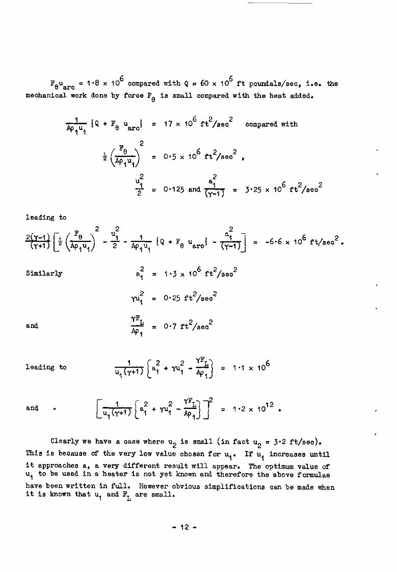
FeU3rc = 1-8 x 10⁶ compared with Q = 60 x IO6 ft poundsls/seo, i.e. the mechanical work done by force FS is small compared with the heat added.
IQ + Fe uarc 1 = 17 x 40' f't2/seo2 compared with
= 0.5 x 106 ft*/sec* ,
2 "i
2
2 = 0.125 and a1
3.25 10 6 2
(yl) = x ft. /sea*
leading to
~[+(;;)'-$j&~Q+F,&,i -$q] = -6.6 x 406 ft/sec2.
Similarly
and
leading to
2 9
= l-3 x IO6 ft2/seo2
2 9
= 0.25 ft2/seo2
YFL - API
= 0.7 f&3ec2
and . [*la: ++?)-J = 1~2x10¹².
Clearly we have a cease where u2 is small (in faot u2 = 3.2 ft/sec). This is because of the very low value ohosen for u,. If u, increases until it approaches a, a very different. result. will appear. The optimum value of u, to be used in a heater is not yet known and therefore the above formulae have been written in full. However obvious simplifications can be made when it is known that u, and F L are small.
- 12 -

3.6 Magnitude of us
*e U =-,
8 %lUl (6)
From above 36 < FD c 36 x IO* pour&& and Ap,u, = 3.6 lb/sea so
10 c us < IO3 pt/seo .
These values of us must be oompared with u, = 0.5 and u2 = 3.2 ft/seo. It is olear that the gas at the heater exit may have a very large swirl component of velooity,
4 DISCUSSION OF RESULTS
4.1 Shortoominss of flow model
The major fault with the flow model presented is obviously the negleot of the radial omuponent of foroe produced when the current has a oiroumferential oompbnsnt and also the neglect of the power developed by this foroe as the aro moves outwards. Unfortunately both these quantities depend upon the sro shape. However if we assume that the arc is of involute shape? then we oan proceed. Fig.3 illustrates that
6FR = I BL 00s a 68
also 6r/i% = sin a
I and for an involute sin a = r,/r where r, is the radius of the inner eleotrode. Substitution gives
6FR s I BL
gives Integrating from r, to r2, where r2 is the diameter of the outer electrode
_- __.-__-_ _ _ _ _. _ -..
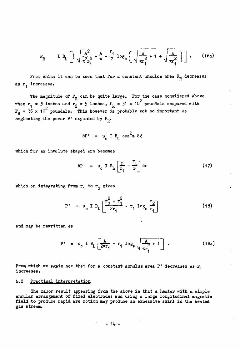
% = IBL~~($--,-~loge[~+ J($-,)]. (16)
This may be rewritten in terms of r, and A as
- 13 -
--- r--
FR A2 A '1 ~t;-~loge
1
[J-$tj tj$j]o Wa)
From which it can be seen that for a constant annulus area FR decreases as r, inoreases.
The magnitude of FR can be quite large. For the case considered above when r 1 = 3 inches and r2 = 5 inches, F R = 31 x IO2 poundals compared with
FfJ = 36 x lo2 poundals. This however is probably not so important as neglecting the power P' experded by FR.
bP’ = uc I BL oos2u 64
which for an involute shaped arc becomes
BP’ = ucI,[=q~]br
which on integrating from r, to r2 gives
2 2 P' = '0 I BL r
- r1 22r
'2 -
1 r, 1065, r 1 1 and may be rewritten as
cIBL 5-k i --
P' = u 1
- r, log, -+I . q-1
(17)
(18)
(18.3)
From which we again see that for a constant annulus area P' decreases as r, increases.
4.2 Practical interpretation
The maJor result appearing from the above ia that a heater with a simple annular arrangement of fixed electrodes and using a large longitudinal magnetic field to produce rapid arc motion may produce an excessive swirl in the heated gas stream.
-14-
The swirl till produce a radial pressure gradient whioh will persist as long as the swirl exists. In addition there is an outward body force aoting in the sro region which locally will increase the pressure gradient.
The results also show that with a low inlet velocity there will be very little change of longitudinal velooity through the are region in spite of the inolusion of the body foroes in the equations.
. For use with a wind tunnel it will be neoessary to remove the swirl before the gas enters the sonic throat presumably by inserting vanes into the flow. These will need to be cooled and must introduce large heat losses. Consideration should therefore be given to alternatives.
The original reason for introducing the rapid are motion was to minimise eleotrcde erosion and it has boon suggostod that
where I max is the maximum are current (amps) and u. the arc velooity over the electrodes (ft/seo). ho further information on this practical limit has reached the author. Accepting that there is such a limit and that a high value of uo is essential then three alternatives to the simple annular arrange- ment appear possible. Firstly the eleatrodes could rotate relative to the gas stream, the arc remaining stationary or slow moving. Seaondly a geometry oould be evolved where only the ends of the aro move, the column being restrained by passing the arc through orifioes and shielding the majer part from the magnetia field. Thirdly swirl could be given to the air entering the chamber and removed by the sro.
The third suggestion appears the most praotioal but it has the dis- advantage that for a given current and magnetic field uc will be reduoed.
Finally the outward radial force on the are, slwsys present with the annular geometry, is a praotical nuisance. The obvious arrangement that avoids this problem is to use an inward flow type heater where the ring electrodes are of equal size and the arc, driven by a radial magnetio field, generates the surface of a cylinder as it rotates.
i CONCLUSIONS
By treating the flow through an annular eleotrio aro heater as that through a linear cascade, where the usual aerofoils are replaced by the electric arc, a method of oaloulating the resultant flow at a station down- stream of the are has been presented. The resultant eleotromagnetio force on the arc is equal and opposite to the drag on the sro which in turn is in the direction of the relative incident air stream. In spite of the arc having no lift (any force normal to the relative velocity), it is shown that when the drag and circumferential aro velocity are large a oonsiderable amount of swirl is produoed in the outgoing air stream.
- 15 -

The model neglects the radial component of the force acting on the arc and the work done by this component (para.4.1). However, in aw practioal design,efforts will be made to minimise this force for a number of reasons.
To determine the outlet flow the following must be known:-
the heater geometry,
the inlet temperature, pressure and mass flow,
the arc current,
the applied magnetic field,
and the voltage across the electrodes.
In addition experimental or theoretical relationships are required to determine the arc velocity, the voltage gradient in the column snd the voltage drops at the eleotrcdes.
To use the method for suooessful. arc heater design an additional equation is required involving the eleotrode erosion such as equation (19).
The model will assist the rational consideration of alternative heater geometries and clarifies our need for more information on:-
uc, the arc velocity,
E, the voltage gradient in the column,
1, the current,
V*, the electrode volt drops,
and I max, the erosion limit.
All the above must be investigated over the full range of working oonditions.
- 16 -
$$FEP.ElNCES Tifilm I/
The inf'luence of gas streams and. magnetic fields on electric discharges. Part I. Arcs at atmospheric pressure in annular gaps. A.R.C. C.P.743. June, $963.
The influence of gas streams and magnetic fields on electric diaohargea. pert2. The shape of an arc rotating round an annular gap. A.R.C. C.P.743. June, 1963.
No, Author I-
I Adams, V.W.
2 A&ma, V.W.
3 Lord, 1t.T. Some magneto-flui&iynemic problems involving electria arca. A.R.C. 25270. August, $963.
4 Crabtree, L.F. A survey of future problems in hyperaonio flow and the Shaw, J.M. experimentel facilities require& for their investigation.
Unpublished AL0.A. Report. October, 1962.
- 17 -


AFPENDIX,l
CONSIDERATION OF THE WAKE BEHIND THE ARC
1 INTRODUCTION
In the above note discussion is limited to conditions in the tw%. planes (1) and (2) remote ftim the arc. When the throughput in the arc ohamber is low and the arc advances partly into its own wake little else oan be done. However, the author has been asked to consider the ease where the throughput is suffioient to ensure that the rotating arc leaves a discrea wake. In this case some olarifioation of events between stations (1) and (2) is possible.
It has slso become apparent. that some readers find it easier ti oonsider the ease where the arc is regarded as stationary but then have diffioulty in seeing how an aro, regarded as a solid body experiencing drag but no lift, can produce a swirl in the exit gas stream. To clarify these points the following disoussion is based upon a stationary arc model and to avoid confusion with the main text it is presented in sn Appendix.
2 FLOW BdODEL
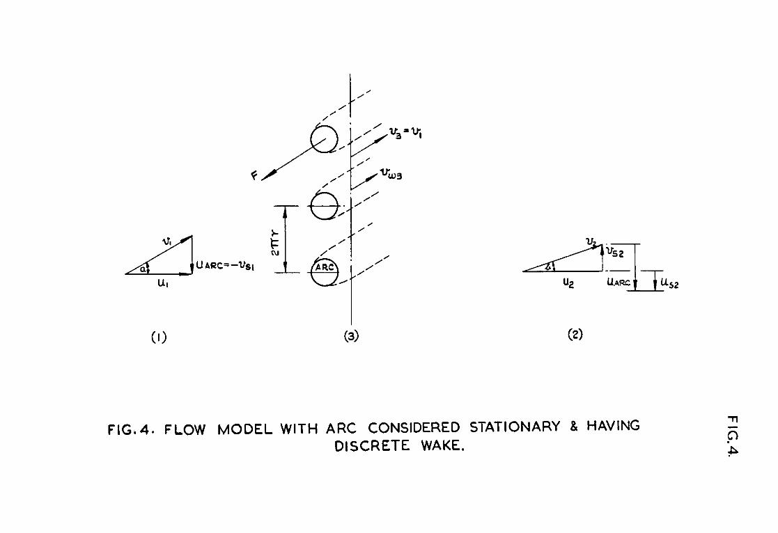
The approximate flow model adopted is illustrated in Fig.& For simpli- city the oase where r, += whilst (r2 - r,) remains finite will be oonsidered, thus avoiding all referenoe to ourvature of the aro and effects thereby intro- duoed. 'The aro is oonsidered as a rigid body giving up heat to the air whioh flows past it.
In the centre of Fig.4 is shown the heater annulus straightened into a "cascade". The distance between the sros is the circumference of the aro heater 2wr and A = 2xr(r2 - r,) is the heater annulus area.
Consideration is again given to conditions at stations upstream (1) and downstream (2) of the heater plane. In addition a station (3) is considered immediately behind the ares where discrete wakes exist but sufficiently far from the ares for the static pressure to be constant across the station. At stat&n (3) all the effects of the aro are assumed to be confined to the wake regisns and the flow outside the wake is assumed to be unaffeoted. (This model is in fact never completely realised in a closed duct. It should be noted that the above assumptions imply that A3 > A, so that the duct must be assumed to expand after station (i) returning to the original area at station (2).)
The air velocities relative to the aro are designated v where tiypioally
The air velocities relative to the chamber are designated u as before and suffioes (I), (2) and (3) refer to the above stations. In addition suffix 8 refers to a swirl or oircumferential component of velocity and suffix w to a mean wake velocity.
- 18 -

Downstream of station (3) a mixing process is assumed whereby the wake type flow is smoothed until uniformity is achieved at station (2).
Finally, a single force F is assumed to act on the arc in a direction opposite to v,, where
3 ANALYSIS
The station (3 P
rooedure adopted is firstly to write down the conditions at in terms of conditions et station (I) and an arbitrary division
of the flow between the wake and the undisturbed region treating F and Q as known quantities, then to apply the conservation of momentum principle to the peripheral oomponent of momentum whilst passing through the mixing zone between stations (3) end (2). It is thus shown that swirl is produced and after converting from Y to u the same formula results as before, i.e. equation (6).
To proceed further it is neoessary to solve simultaneously the con- tinuity, momentum and energy equations. This is beoause there is a pressure change in the mixing region whioh directly effects the axial. momentum. This was done in the main text. Here the conservation equations are written firstly in terms of v equating conditions in region (3) to region (2). These are then transformed to u values and the original equations produoed.
We thus show how vs2 depends primarily on F and u2 primarily on Q and F through the continuity, momentum and energy equations. In general v2 will not be in the direct&n of vi.
At station (3) the total mass flow per unit time = Ap,u,
Assume the wake flow =- k +I?
and the unsffeoted fits
(20)
(24)
(22)
The momentum equation applied to the wake flow then gives
and
F = : Ap,u, b, - VW31 (23)
Fn vw3 = v1 - - l
*PIUl
(24)
- 19 -

Appendix 1
Rate of momentum in wake flow passing station (3)
and rate of momentum in kdisturbed flow passing station (3) = $$ %"lvI'
Finally, considerin between stations (I) and 2) gives t
just the wake flow, the conservation of energy .
or
Q = - _ :, Ap,u, Cp(Tw3 - T,) + N.B. P, = P WJ
C T P w3
= $fq+C T -$+$, P 1 (25)
3.1 Momentum in oircumferential direotion
We oan now equate the momentum at station (3) to momentum at station (2) taking components in the plane of the sro.
+l"l v3 sin a = Aqu, v2 sinb
Ol-
Le.
:(v, - $q) sin a +(i?;;'> v, sin a = v2 sin b
v sina F 1
-- sina e: v2 sinb . QIUl
From Fig.4
(26)
-2o-

Appadix 1
Substituting in equation (26) gives
F U arc
- - sin a = u @I"1
BCC - Ua2
or Fe
U s2 = - Ap1 Y
as before . (6)
Clearly us2 = C only when Fe when Fe finite +ve and angle
= 0 i.e. vs2.= uarC when Fe = 0. Also vs2 < uarc a = b when
L u2 5 -. U v
are 82 (27)
3.2 Momentum in longitudinal direction
Next, equating the axial components of momentum at stations (3) and (2) and writing in terms of velocities relative to the arc, gives
[i +l”i (7 - 6) +(fl;;L> Ap,u, v,] cos a - Ap,u, v2 cos b = (P2 - P,)A
..* (28)
i.e. [p,u? [G +ce) v,] - f] co8 a - p,u, v2 cos b P P2 - P,
or FL P,“,(U, - u2) - T = P2 - P,
which may be rewritten as before
FL P1U,(U2 - u,) = P, - P2 -'j;- .
(29)
(24
3.3 Energy equation
Similarly, we may equate the energy at station (3) to the energy at station (2).
- 21 -

Appendix 1
+ AP,u, ,-
Cp Tw3 + $) +(%) AP,u, {Cp T, + $) = Ap,u, [Cp T2 + 4).
. . . (30)
Eliminating C T P w3
by using equation (25) yields
+ Cp T, +$) +(+)(Cp T, t$ = Cp T2 +$
$'q + Cp T, + $ 2
= Cp T2 + 2 . or (31)
This equation is olearly the equaticn obtained if the energy at station (1) ia equated to that at station (23 allowing for the heat added and using axes fixed relative tc the arc.
Equation (31) may be rewritten
2 2 u, + u 2 2 -e,+C T + am u2 + vs2 Ap,u, p ' 2 = Cp T2 + 2 .
FigA+ shows that
v s2 = U -u arc s2
80 that
q$-, + Cp T, ; 3 +. $
2 XU
2 = Cp T2 + 9 + +(uapo - us2)2
U2 -D C U s2
am 82 +-. 2 .- 1
Substituting for ua2 from equation (6) gives .d , . __
2 2 2 +C u1 T +- u2 Fe
P1 2 = cPT2+-5---u us2
Ap,u, arc +-a 2
- 22 -

Appendix I
which may be rewritten as
2 Y F+C T+
P' +C T
P 2' (3)
which is the original equation (3).
4 CONCLUSIONS
We thus see that results achieved using the above model for conditions at station (3) will be consistent with the main text, whioh oonsidered only stations (1) and (2), in as much as the same momentum and energy equations are obtained.
The immediately obvious condition that the are shall have a discrete wake at station (3) is that
where w3 is the width of the arc wake at station (3) measured normal to v,. However, inspection of the continuity equation reveals that the supposition of a disoreta wake and an unaffected flow region demands an increase in cross- section at station (3). The actual value depending upon F, Q and n. In a . practical heater there will probably be a constant or decreasing area and we may then deduce that there must be interference between the flow patterns about adjacent arcs in the cascade. Although there will be only one arc in a heater, this nevertheless means that suitable allowance for this “oascade" interference must be made when applying results from, say a single aro travelling along straight rails, to the case of an are rotating in an annular gap*
The aahievement of a heater suitable for wind-tunnel pur oses will be oritically dependent upon the mixing process between stations P 3) and (2), beoause it is this which will produoe the uniform conditions required at station (2). It is shown above that in general the flow turns between stetiCins (3) and (2) and, in as much as the wakes can be followed through the mixing process, they will be found to turn also.
Electrioelly, the significance of this investigation is that, an are with a discrete wake will be moving into unheated air and then aan be expected to have a higher column voltage gradient than a similar arc moving intc its own wake. It would appear reasonable to expect that in en arc chamber the voltage gradient would ohenge abruptly at a particular throughput where the wake became discrete.
- 23 -
Printed rn h’nhglmd for Rer Majesty’s Stattonery Offrce by the Royal Awcsajt Estoblishxent, Famboso?@h. Y.~.dO.B.U.

/ ///
FIG.1. ANNULAR ARC HEATER.
FIG. 2. FLOW MODEL.
FIG. 3. FORCES ON ARC.
c /’ / /’
FIG.4. FLOW MODEL WITH ARC CONSIDERED STATIONARY 8 HAVING DISCRETE WAKE.

621.365.2: A&C. C.P. NO. 779 533.6.071:
553.6.011.5
ASIMPLEl7XIMOD OFCAUXLATING THE FLOW FRODUCDIN AN ANNULAR ELDXXIC ARC HEATW. maw. J.M. November 1963.
This note desorlbes a simple model from whit,' the flow In a" arnuk electric am heater oa" be calculated. It is intended W clarify ideas about such heaters, to dimot thought to eltemtlve possibly better types and to guide Mp%Went.al mrk. When mre e~rlmentalandtheorrticalmsults are available ltcanfomtbe basis from Hdlich heaters ml@. be deslmed.
I A&C. C.P. No. 7i¶ 621~65.2: V3.6.071: 533.6.011.5
A SIMPZE i%lliOD OF CAUXKATING THE FIB" PROWCLI) IN AN iWI".JR EL~TRIC ARC HEATER. maw, J.M. No"mbcr 1963.
Thts mate describes a Simple model rmm tilcb the flow In a" anm~lar electric arc beater can be calculated. It IS intended to clarify ideas about swh beaters, to dlreot tboughC to alCen,atlve possibly better typs and to guide sx~rlmnMl work. When more experlmentalmdthm-?tical rem1tsar-e available lt can fomtbe basis tmm Vmlch heaters ml&it be designed.
OZTW)
A.RC. C.P. N0.7?9
oJw-1
621.365.2: 33.6.071: 533.LO11.5
ASIHPLE HFntOD OFCUX.ATING IXEFLO” A(ODuCFD IN AN MN”LX, LznrpRIC ARC HEAm. E-m, J.H. Novenber 1%3.
This note describes a simple male1 Irmn vdllch the flow In an amuI.ar electric arc heater ca" be aalculated. It is intended to clarify ldw abo"t such heaters, to dhot thou&t to alternative asslbly batter typss and to guide e.XwlmmW no-k. when mom e.xperiuent.alandthsonticalmsults are mallable Itam ronnthe basis from v&M, i-ater.8 r&?ht be &Sf@w&

It 1s sbom that the simple p-educe excesSlve mirl in the suggested,
I ,%xount ls taken in Cbe
the fames produced by the arc current.
It is shorn that the simple annular type of heater will probably It Is ahorn that the simple prcdwe cxcess1ve swirl In the Outlet air 8tmanL Altcm¶t1ves are pmduoe exossaln stir1 in tile suggest.ed. 8uggested.
lccaunt is taken in the theory of both tk? heat addltfon and the lmcs prcduosd by the ~temotim of magnetic lisJds with the am Cmt.


C.P. No. 779
Pubbshcd by Hra M.uE.QY’s STATIONERY OFFICZ
To be purchased from York House. Kmgsway. London w c.2
423 Oxford Street. London w.1 13~ Castle Stnet. Edmburgh 2
109 St Mary Street. Card8 39 Kmg Street, Manchester 2
50 FaIrfax Street. Brtstol 1 35 Smallbrook. Ringway, Bnmmgham 5
80 Chchester Street. Belfast 1 or through any bookseller
C.P. No. 779 S.O. CODE No. 23-9015-79