Embed Size (px)
Citation preview
Journal of Power Sources 141 (2005) 326–339
A simplified physics-based model for nickel hydrogen battery
Shengyi Liua,∗, Roger A. Dougala, John W. Weidnerb, Lijun Gaoa
a Department of Electrical Engineering, University of South Carolina, Columbia, SC 29208, USAb Department of Chemical Engineering, University of South Carolina, Columbia, SC 29208, USA
Received 23 August 2004; accepted 30 September 2004Available online 7 December 2004
Abstract
This paper presents a simplified model of a nickel hydrogen battery based on a first approximation. The battery is assumed uniformthroughout. The reversible potential is considered primarily due to one-electron transfer redox reaction of nickel hydroxide and nickeloxyhydroxide. The non-ideality due to phase reactions is characterized by the two-parameter activity coefficients. The overcharge process ischaracterized by the oxygen reaction. The overpotentials are lumped to a tunable resistive drop to fit particular battery designs. The modelis implemented in the Virtual Test Bed environment, and the characteristics of the battery are simulated and in good agreement with thee ellite powers©
K
1
gmditlfimup
itcte
e as-tionsics.weenhe gasectro-rmly
s thef the
Bedd-mal)andwiththeert-ringbient
ult ofther-
0d
xperimental data within the normal operating regime. The model can be used for battery dynamic simulation and design in a satystem, an example of which is given.2004 Elsevier B.V. All rights reserved.
eywords:Nickel hydrogen battery; Non-ideal reversible potential; Overcharge; Self-discharge; Resistive-companion model
. Introduction
Complicated electrochemical processes in a nickel hydro-en battery[1,2] involve more than eight reactions includingain reactions, phase reactions, and side reactions. While aetailed model has been developed[3,4], it is currently coded
n discipline-specific languages and for standalone simula-ion only. Thus, it is not in general available for use in systemevel simulation and design. This paper presents a simpli-ed, yet still physics-based, model that can be rapidly imple-ented and conveniently used for the battery dynamic sim-lation, design, and optimization in complicated spacecraftower systems.
The model is based on following considerations. For typ-cal applications (e.g., in spacecraft power systems[5–7]),he charge and discharge of the Ni–H2 battery are in such aontrolled way that the rate of charge and discharge is lesshan 0.5 C to ensure a reliable, safe and long lifetime op-ration[8,9]. Under such a circumstance, the charge, mass
∗ Corresponding author. Tel.: +1 803 777 8966; fax: +1 803 777 8045.
and heat transport, and the phase equilibrium can bsumed to complete instantly. Thus, the kinetics of reacis less likely a limiting factor to the external characteristThis leads to the assumption that the boundaries betthe electrodes and the separator, and those between tphase and solid phase in the battery vanish, and the elchemical and electrothermal processes take place unifothroughout the battery. This assumption greatly simplifiemodeling process while observing the major features obattery.
The present model is implemented in the Virtual Testsoftware environment[10], in which the battery is consiered as an interdisciplinary (chemical, electrical and thersystem governed by physics laws under certain initialboundary conditions. Given a time, the battery interactssurroundings in two ways: it delivers electrical power toload at its electrical terminals during discharge by conving chemical energy into electric one (or the reverse ducharge process), and it absorbs or releases heat to amat its external surface. Thus, the battery voltage is a rescoupled electrochemical, chemical-thermal and electro
E-mail address:[email protected] (S. Liu). mal processes.
378-7753/$ – see front matter © 2004 Elsevier B.V. All rights reserved.oi:10.1016/j.jpowsour.2004.09.035
S. Liu et al. / Journal of Power Sources 141 (2005) 326–339 327
Nomenclature
A electrode area (m2)a specific area (m2 m−3)bj(t−h) time history for the through variable at termi-
nal jCb battery capacity (A h)cp average specific heat (J kg−1 K−1)ENi total reversible potential (V)EO2 oxygen reaction potential (V)h simulation time step (s)F Faraday constant (96,485 C mol−1)gj,k admittance of a through variable at terminalj
with respect to an across variable at terminalkL+ electrode thickness (m)m battery cell mass (kg)iNi nickel reaction current (A)iO2 oxygen reaction current (A)iO2,0 oxygen exchange current density (A m−2)iT thermal current (W K−1)nH2 amount of hydrogen (mol)P across variable for the pressure terminal (Pa)p pressure (Pa)Qmax maximum charge stored in the battery (C)R gas constant (8.314 J mol−1 K−1)Ri internal resistance (�)T battery bulk temperature, also across variable
for thermal terminal (K)t independent variable time (s)Vg volume of battery (m3)v battery terminal voltage (V)va, vc across variables for anode and cathode (V)x state of dischargeαO2 oxygen reaction transfer number (0.75)
The solution to the coupled processes is obtained by meansof the resistive-companion (RC) method[11], which requiresthe governing equations to be time-discretized to a standardmatrix formulation in terms of across and through variables.The resulted matrix equations are then simultaneously solvedthrough the VTB time-domain simulation using the nodalanalysis approach.
2. Model description
2.1. Electrochemical process
The deviation of the reversible potential of the nickel elec-trode from the ideal Nernst equation, or its non-ideality, wasinterpreted[12] as due to intercalation of multi-phases, in-cluding �- and�-phase of nickel hydroxide, and�- and�-phase of nickel oxyhydroxide. When discharging, it yields
higher capacity[4] than that obtained from a single-phasenickel oxyhydroxide. As a first approximation, the overall po-tential can be characterized as if a usual one-electron transferredox reaction occurs between nickel hydroxide and oxy-hydroxide, but with the incorporation of the effects of bothnon-ideality due to multi-species of active nickel materialsand the potential due to hydrogen reaction at the platinumelectrode.
To characterize the overcharge process, the oxygen reduc-tion is considered. It was believed[4] that the water oxida-tion/reduction (or oxygen evolution) at the nickel electrodeand the oxygen reduction at the platinum electrode plays adominant role in an overcharge process, causing a large por-tion of the current wasted. For normal charge and discharge,the oxygen reduction yields a negligible current.
Based on the above descriptions, the electrochemical reac-tions that characterize the energy conversion between chemi-cal and electrical forms in the Ni–H2 battery are given below.
At the nickel electrode are the nickel reduction/oxidationand the water reduction/oxidation:
NiOOH + H2O + e− charge�
dischargeNi(OH)2 + OH−, (1)
1
2O2 + H2O + 2e− � 2OH−. (2)
andt
E
oft
A
B
C
D
E
w ofn therda
At the platinum electrode are the hydrogen reactionhe oxygen reduction:
1
2H2 + OH− charge
�discharge
H2O + e−, (3)
12O2 + H2O + 2e− → 2OH−. (4)
The overall reversible potential can be described as:
Ni (T, x) = E0Ni
(T ) + RT
Fln
(1 − x
x
)
+ RT
2F[A0(T )C(x) + B0(T )D(x)]. (5)
The third and the last term in(5) are the characteristicshe non-ideality, and,
0(T ) = a0 + a1T, (6)
0(T ) = b0 + b1T, (7)
(x) = c0 + c1x, (8)
(x) = d0 + d1x + d2x2, (9)
0Ni
(T ) ={e0d + e1T, for discharge
e0c + e1T, for charge, (10)
hereai , bi , ci , anddi are constants for phase activitiesickel species, which may vary from one battery to anoue to different contents and pore structures.e0c, e0d ande1re also constants. The difference betweene0c ande0d in (10)
328 S. Liu et al. / Journal of Power Sources 141 (2005) 326–339
is used to characterize the hysteresis of proton intercalationin nickel hydroxide electrode[13,14].
Under the assumption of a uniform and non-kinetic limitedreaction, the current from oxygen reaction can be calculatedaccording to the Butler–Volmer equation,
iO2(v, T ) = AL+ai0,O2(T )
× exp
[4(1− αO2)
F
RT(v − EO2(T ))
], (11)
where the exchange current density is of the Arrhenius type[3,4], and,
EO2(T ) = 1.730− 0.00168T, (12)
aiO2,0(T ) = 10.0 exp
[−12,025
(1
T− 1
298
)]. (13)
Eq.(12)is the simplified equilibrium potential of the oxy-gen reaction depending upon the temperature only. The nu-merical parameters appeared in(12) and(13) are calculatedbased on the data in references[3,4] that are specifically ap-plied to the oxygen reaction in Ni–H2 batteries.
The state of dischargex can be conveniently related to thenickel reaction current as:
dx = − iNi . (14)
rent:
v
all ita-t r-a bat-t Eqs.( icalp
2
thee er-m cess,e heata e oft nergyb
c
g tot (1)p
which are irreversible electrothermal processes; and (2) en-tropic heat includingiNiT (dENi/dT ) and iO2T (dEO2/dT ),which are reversible chemical-thermal processes. The lastterm on the right-hand side is the heat transported to (orfrom) the surroundings through the battery surface or thethermal terminal, which is expressed as the product of thethrough variableiT (thermal current) and the across variableT(temperature).
2.3. Pressure modeling
The hydrogen pressure in the battery is an indicator forthe state of discharge (hydrogen content) under the conditionof regulated charge/discharge. Thus, a built-in sensor is usedto detect the pressure[5], so that aV/P (voltage/pressure)control can be implemented to prevent the battery fromovercharge. Assuming the ideal gas law applies, we thenhave:
p = nH2RT
Vg
, (17)
dnH2
dt= iNi
2F, (18)
nH2|t=0 = 3600Cb
2F(1 − x|t=0) (19)
ula-t ns int argei ill bei
3
byE alsf ale inal;a Thet f theb fora isc
i ternalc entf vari-a xter-n fromt theb con-d inali sen-s portf tual
dt Qmax
The battery terminal voltage can be related to the cur
= ENi + RiiNi . (15)
The fitting parameterRi accounts for the overall internoss due to ohmic, surface kinetic and concentration limions. Since the internal loss in the Ni–H2 battery is genelly small compared to most of other major secondary
eries, we simply use a small constant to approximate.4)–(15) complete the descriptions of the electrochemrocess.
.2. Thermal process
To simplify, we consider the heat generations due tonthalpy of reactions[15] and the heat transported at the thal terminal only, whereas the heat due to isometric pronthalpy of mixing, phase change and change of specificre ignored without introducing significant error. The rat
emperature change of the battery is governed by the ealance equation:
pmdT
dt= iNi
(v − ENi + T
∂ENi
∂T
)
+ iO2
(v − EO2 + T
∂EO2
∂T
)+ iTT. (16)
The first two terms on the right-hand-side are owinhe enthalpy of reactions, which can be identified asolarization heat includingiNi (v − ENi ) and iO2(v − EO2),
The partial pressure of oxygen is ignored in this calcion. This is based upon the assumption that the reactiohe battery are uniform throughout, and the charge/dischs not so fast that any appreciable oxygen produced wmmediately removed via reaction (4).
. VTB implementation
The VTB implementation of the model describedqs. (5)–(19) involves (1) defining appropriate termin
or power or signal coupling; (2) deriving the terminquations in their standard RC format for each termnd (3) developing C++ code for computer execution.
ime-domain solution for coupled physics processes oattery can then be obtained through VTB simulationny given circuit configurations to which the batteryonnected.
The physical electric terminals of the Ni–H2 battery arets anode and cathode that can be connected to an exircuit for electrical power coupling. Naturally, the curror the through variable and the potential for the acrossble are defined. The physical thermal terminal is the eal surface through which the heat can transfer to or
he surroundings. By definition, the thermal terminal, orattery surface can transport heat power by means ofuction, or radiation, or convection. The pressure term
s a signal terminal. The signal from a built-in pressureor is coupled to an external circuit through this signalor monitoring or control purposes. Thus, there is no ac
S. Liu et al. / Journal of Power Sources 141 (2005) 326–339 329
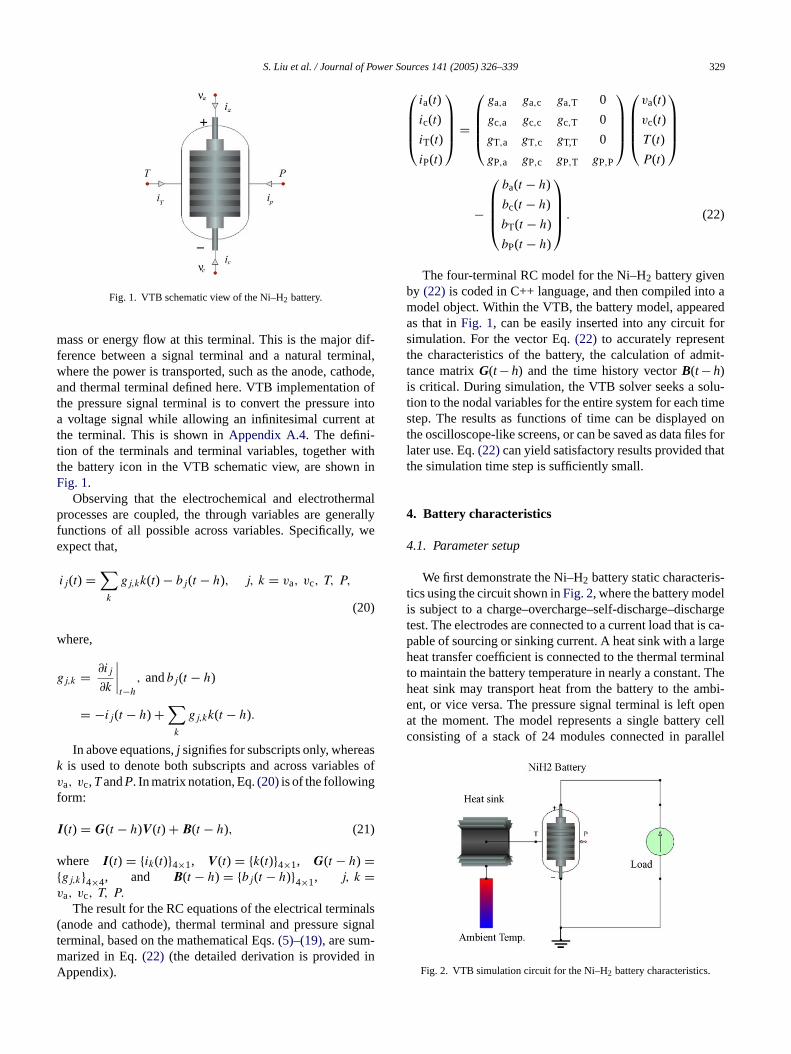
Fig. 1. VTB schematic view of the Ni–H2 battery.
mass or energy flow at this terminal. This is the major dif-ference between a signal terminal and a natural terminal,where the power is transported, such as the anode, cathode,and thermal terminal defined here. VTB implementation ofthe pressure signal terminal is to convert the pressure intoa voltage signal while allowing an infinitesimal current atthe terminal. This is shown inAppendix A.4. The defini-tion of the terminals and terminal variables, together withthe battery icon in the VTB schematic view, are shown inFig. 1.
Observing that the electrochemical and electrothermalprocesses are coupled, the through variables are generallyfunctions of all possible across variables. Specifically, weexpect that,
ij(t) =∑k
gj,kk(t) − bj(t − h), j, k = va, vc, T, P,
(20)
where,
gj,k = ∂ij
∂k
∣∣∣∣t−h
, andbj(t − h)
= −ij(t − h) +∑k
gj,kk(t − h).
ask les ofv
f
I
w{v
nals( ignalt -m inA
ia(t)
ic(t)
iT(t)
iP(t)
=
ga,a ga,c ga,T 0
gc,a gc,c gc,T 0
gT,a gT,c gT,T 0
gP,a gP,c gP,T gP,P
va(t)
vc(t)
T (t)
P(t)
−
ba(t − h)
bc(t − h)
bT(t − h)
bP(t − h)
. (22)
The four-terminal RC model for the Ni–H2 battery givenby (22) is coded in C++ language, and then compiled into amodel object. Within the VTB, the battery model, appearedas that inFig. 1, can be easily inserted into any circuit forsimulation. For the vector Eq.(22) to accurately representthe characteristics of the battery, the calculation of admit-tance matrixG(t−h) and the time history vectorB(t−h)is critical. During simulation, the VTB solver seeks a solu-tion to the nodal variables for the entire system for each timestep. The results as functions of time can be displayed onthe oscilloscope-like screens, or can be saved as data files forlater use. Eq.(22)can yield satisfactory results provided thatthe simulation time step is sufficiently small.
4
4
s-t eli harget is ca-p rgeh inalt . Theh mbi-e pena cellc allel
In above equations,j signifies for subscripts only, whereis used to denote both subscripts and across variab
a, vc,TandP. In matrix notation, Eq.(20)is of the followingorm:
(t) = G(t − h)V (t) + B(t − h), (21)
here I(t) = {ik(t)}4×1, V (t) = {k(t)}4×1, G(t − h) =gj,k}4×4, and B(t − h) = {bj(t − h)}4×1, j, k =a, vc, T, P.
The result for the RC equations of the electrical termianode and cathode), thermal terminal and pressure serminal, based on the mathematical Eqs.(5)–(19), are sumarized in Eq.(22) (the detailed derivation is providedppendix).
. Battery characteristics
.1. Parameter setup
We first demonstrate the Ni–H2 battery static characteriics using the circuit shown inFig. 2, where the battery mods subject to a charge–overcharge–self-discharge–discest. The electrodes are connected to a current load thatable of sourcing or sinking current. A heat sink with a laeat transfer coefficient is connected to the thermal term
o maintain the battery temperature in nearly a constanteat sink may transport heat from the battery to the ant, or vice versa. The pressure signal terminal is left ot the moment. The model represents a single batteryonsisting of a stack of 24 modules connected in par
Fig. 2. VTB simulation circuit for the Ni–H2 battery characteristics.
330 S. Liu et al. / Journal of Power Sources 141 (2005) 326–339
Table 1Parameter setup for a single Ni–H2 battery cell[4]
Parameter Value Unit
Cell Capacity 30 A hVolume 4.65× 10⁻⁴ m3
Mass 1.2 kgResistance 0.01 �
Surface area 0.06 m2
Specific heat 1000.0 J kg−1 K−1
No. of modules in series 24
Module Electrode area 0.005 m2
Electrode thickness 3.6× 10⁻⁴ m
Table 2Parameters for multi-phase activity
A0(T) a0 = 11.50,a1 =−0.0231B0(T) b0 = 32.00,b1 = 0.060C(x) c0 = 4.590,c1 = 15.80D(x) d0 = 1.800,d1 =−5.680,d2 = 0.350E0
Ni(T ) e0c = 1.609,e0d = 1.470,e1 = 0.00062
and contained in a cylindrical pressure vessel. Each module,characterized by Eq.(22), has a nickel electrode, platinumelectrode, Zircar separator and polypropylene gas screen (fordetailed constructions, please see references[2,4,8,9]). Otherphysical parameters are listed inTable 1. The parameters formulti-phase activity are given inTable 2. In the simulation,the initial temperature is set to the ambient temperature, andthe initial state of discharge is set to 100%.
4.2. Temperature-dependent characteristics
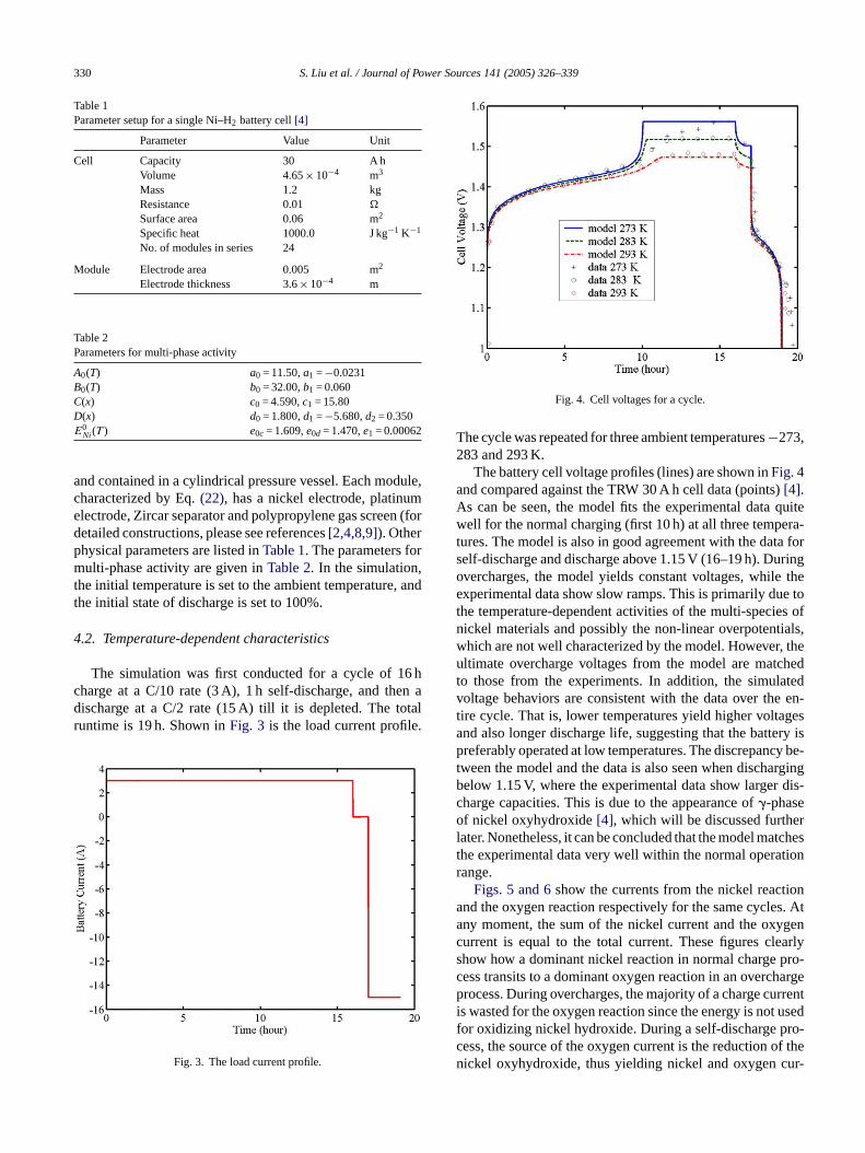
The simulation was first conducted for a cycle of 16 hcharge at a C/10 rate (3 A), 1 h self-discharge, and then adischarge at a C/2 rate (15 A) till it is depleted. The totalruntime is 19 h. Shown inFig. 3 is the load current profile.
Fig. 4. Cell voltages for a cycle.
The cycle was repeated for three ambient temperatures−273,283 and 293 K.
The battery cell voltage profiles (lines) are shown inFig. 4and compared against the TRW 30 A h cell data (points)[4].As can be seen, the model fits the experimental data quitewell for the normal charging (first 10 h) at all three tempera-tures. The model is also in good agreement with the data forself-discharge and discharge above 1.15 V (16–19 h). Duringovercharges, the model yields constant voltages, while theexperimental data show slow ramps. This is primarily due tothe temperature-dependent activities of the multi-species ofnickel materials and possibly the non-linear overpotentials,which are not well characterized by the model. However, theultimate overcharge voltages from the model are matchedto those from the experiments. In addition, the simulatedvoltage behaviors are consistent with the data over the en-tire cycle. That is, lower temperatures yield higher voltagesand also longer discharge life, suggesting that the battery ispreferably operated at low temperatures. The discrepancy be-tween the model and the data is also seen when dischargingbelow 1.15 V, where the experimental data show larger dis-charge capacities. This is due to the appearance of�-phaseof nickel oxyhydroxide[4], which will be discussed furtherlater. Nonetheless, it can be concluded that the model matchesthe experimental data very well within the normal operationr
iona s. Ata genc arlys pro-c hargep rrenti usedf ro-c f then ur-
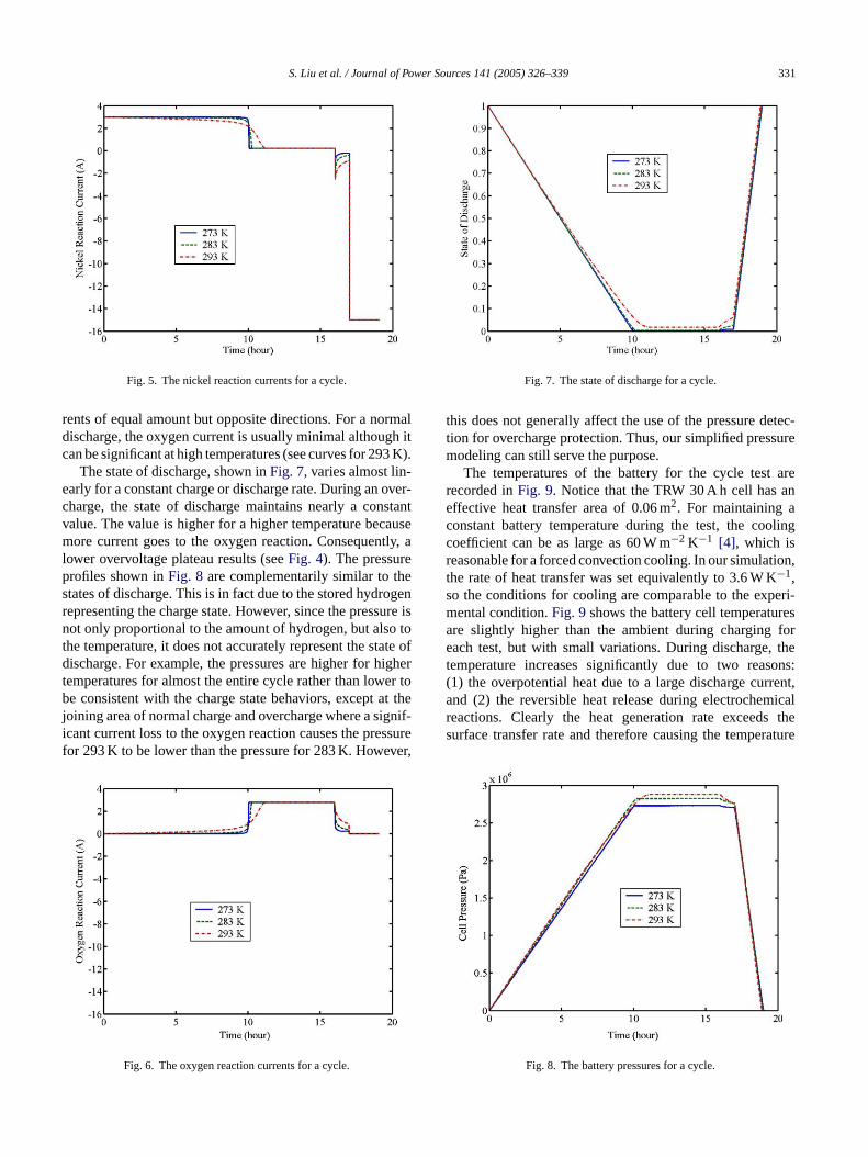
Fig. 3. The load current profile.ange.Figs. 5 and 6show the currents from the nickel react
nd the oxygen reaction respectively for the same cycleny moment, the sum of the nickel current and the oxyurrent is equal to the total current. These figures clehow how a dominant nickel reaction in normal chargeess transits to a dominant oxygen reaction in an overcrocess. During overcharges, the majority of a charge cu
s wasted for the oxygen reaction since the energy is notor oxidizing nickel hydroxide. During a self-discharge pess, the source of the oxygen current is the reduction oickel oxyhydroxide, thus yielding nickel and oxygen c
S. Liu et al. / Journal of Power Sources 141 (2005) 326–339 331
Fig. 5. The nickel reaction currents for a cycle.
rents of equal amount but opposite directions. For a normaldischarge, the oxygen current is usually minimal although itcan be significant at high temperatures (see curves for 293 K).
The state of discharge, shown inFig. 7, varies almost lin-early for a constant charge or discharge rate. During an over-charge, the state of discharge maintains nearly a constantvalue. The value is higher for a higher temperature becausemore current goes to the oxygen reaction. Consequently, alower overvoltage plateau results (seeFig. 4). The pressureprofiles shown inFig. 8 are complementarily similar to thestates of discharge. This is in fact due to the stored hydrogenrepresenting the charge state. However, since the pressure isnot only proportional to the amount of hydrogen, but also tothe temperature, it does not accurately represent the state ofdischarge. For example, the pressures are higher for highertemperatures for almost the entire cycle rather than lower tobe consistent with the charge state behaviors, except at thejoining area of normal charge and overcharge where a signif-icant current loss to the oxygen reaction causes the pressurefor 293 K to be lower than the pressure for 283 K. However,
Fig. 7. The state of discharge for a cycle.
this does not generally affect the use of the pressure detec-tion for overcharge protection. Thus, our simplified pressuremodeling can still serve the purpose.
The temperatures of the battery for the cycle test arerecorded inFig. 9. Notice that the TRW 30 A h cell has aneffective heat transfer area of 0.06 m2. For maintaining aconstant battery temperature during the test, the coolingcoefficient can be as large as 60 W m−2 K−1 [4], which isreasonable for a forced convection cooling. In our simulation,the rate of heat transfer was set equivalently to 3.6 W K−1,so the conditions for cooling are comparable to the experi-mental condition.Fig. 9shows the battery cell temperaturesare slightly higher than the ambient during charging foreach test, but with small variations. During discharge, thetemperature increases significantly due to two reasons:(1) the overpotential heat due to a large discharge current,and (2) the reversible heat release during electrochemicalreactions. Clearly the heat generation rate exceeds thesurface transfer rate and therefore causing the temperature
Fig. 6. The oxygen reaction currents for a cycle.
Fig. 8. The battery pressures for a cycle.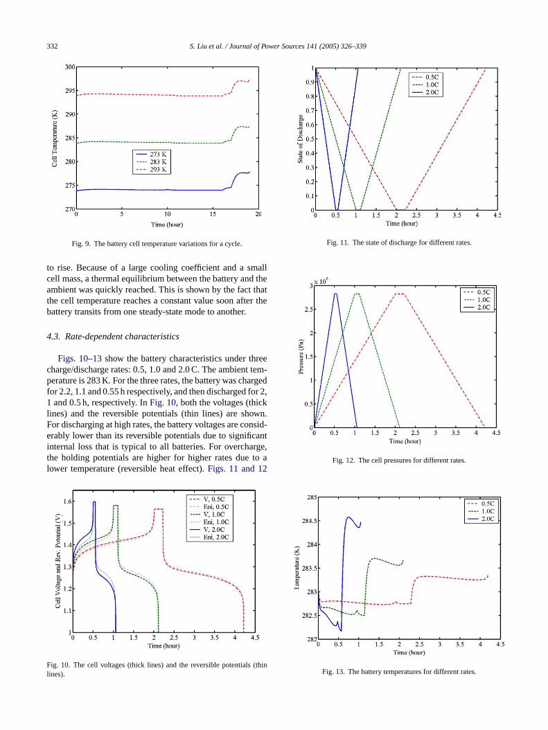
332 S. Liu et al. / Journal of Power Sources 141 (2005) 326–339
Fig. 9. The battery cell temperature variations for a cycle.
to rise. Because of a large cooling coefficient and a smallcell mass, a thermal equilibrium between the battery and theambient was quickly reached. This is shown by the fact thatthe cell temperature reaches a constant value soon after thebattery transits from one steady-state mode to another.
4.3. Rate-dependent characteristics
Figs. 10–13show the battery characteristics under threecharge/discharge rates: 0.5, 1.0 and 2.0 C. The ambient tem-perature is 283 K. For the three rates, the battery was chargedfor 2.2, 1.1 and 0.55 h respectively, and then discharged for 2,1 and 0.5 h, respectively. InFig. 10, both the voltages (thicklines) and the reversible potentials (thin lines) are shown.For discharging at high rates, the battery voltages are consid-erably lower than its reversible potentials due to significantinternal loss that is typical to all batteries. For overcharge,the holding potentials are higher for higher rates due to alower temperature (reversible heat effect).Figs. 11 and 12
F (thinl
Fig. 11. The state of discharge for different rates.
Fig. 12. The cell pressures for different rates.
Fig. 13. The battery temperatures for different rates.
ig. 10. The cell voltages (thick lines) and the reversible potentialsines).
S. Liu et al. / Journal of Power Sources 141 (2005) 326–339 333
are the correspondent states of discharge and pressures forthe three rates, showing similar characteristics to those inprevious simulations.
Fig. 13shows the cell temperature for the three rates. Itis lower than the ambient during charging processes, higherthan the ambient in discharging processes. Apparently, thereversal of the entropic heat in charging process causes thetemperature to drop. During discharging, the release of en-tropic heat and irreversible heat result in higher temperatures.It is worth to remark that the temperature drop during charg-ing was also noticed in reference[4]. Our next work is toimprove the thermal modeling once the data are available forcharacterization.
5. Battery dynamics in a system
5.1. System description
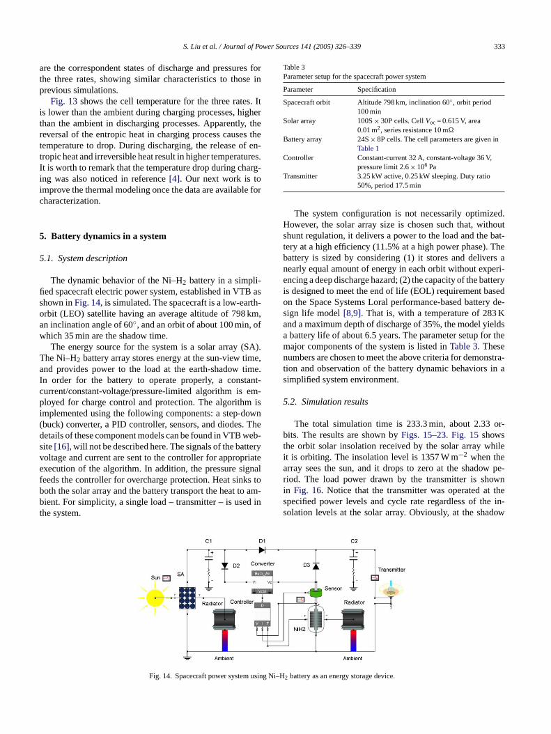
The dynamic behavior of the Ni–H2 battery in a simpli-fied spacecraft electric power system, established in VTB asshown inFig. 14, is simulated. The spacecraft is a low-earth-orbit (LEO) satellite having an average altitude of 798 km,an inclination angle of 60◦, and an orbit of about 100 min, ofwhich 35 min are the shadow time.
SA).T ime,a time.I ant-c em-p isi own( . Thed eb-s teryv riatee gnalf ks tob am-b d int
sing N
Table 3Parameter setup for the spacecraft power system
Parameter Specification
Spacecraft orbit Altitude 798 km, inclination 60◦, orbit period100 min
Solar array 100S× 30P cells. CellVoc = 0.615 V, area0.01 m2, series resistance 10 m�
Battery array 24S× 8P cells. The cell parameters are given inTable 1
Controller Constant-current 32 A, constant-voltage 36 V,pressure limit 2.6× 10⁶ Pa
Transmitter 3.25 kW active, 0.25 kW sleeping. Duty ratio50%, period 17.5 min
The system configuration is not necessarily optimized.However, the solar array size is chosen such that, withoutshunt regulation, it delivers a power to the load and the bat-tery at a high efficiency (11.5% at a high power phase). Thebattery is sized by considering (1) it stores and delivers anearly equal amount of energy in each orbit without experi-encing a deep discharge hazard; (2) the capacity of the batteryis designed to meet the end of life (EOL) requirement basedon the Space Systems Loral performance-based battery de-sign life model[8,9]. That is, with a temperature of 283 Kand a maximum depth of discharge of 35%, the model yieldsa battery life of about 6.5 years. The parameter setup for themajor components of the system is listed inTable 3. Thesenumbers are chosen to meet the above criteria for demonstra-tion and observation of the battery dynamic behaviors in asimplified system environment.
5.2. Simulation results
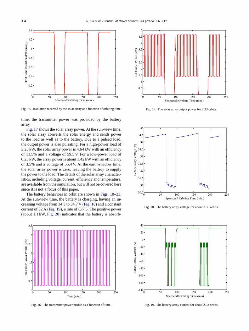
The total simulation time is 233.3 min, about 2.33 or-bits. The results are shown byFigs. 15–23. Fig. 15 showsthe orbit solar insolation received by the solar array whileit is orbiting. The insolation level is 1357 W m−2 when thearray sees the sun, and it drops to zero at the shadow pe-riod. The load power drawn by the transmitter is showni thes e in-s dow
The energy source for the system is a solar array (he Ni–H2 battery array stores energy at the sun-view tnd provides power to the load at the earth-shadow
n order for the battery to operate properly, a consturrent/constant-voltage/pressure-limited algorithm isloyed for charge control and protection. The algorithm
mplemented using the following components: a step-dbuck) converter, a PID controller, sensors, and diodesetails of these component models can be found in VTB wite[16], will not be described here. The signals of the batoltage and current are sent to the controller for appropxecution of the algorithm. In addition, the pressure sieeds the controller for overcharge protection. Heat sinoth the solar array and the battery transport the heat toient. For simplicity, a single load – transmitter – is use
he system.
Fig. 14. Spacecraft power system u
i–H2 battery as an energy storage device.n Fig. 16. Notice that the transmitter was operated atpecified power levels and cycle rate regardless of tholation levels at the solar array. Obviously, at the sha
334 S. Liu et al. / Journal of Power Sources 141 (2005) 326–339
Fig. 15. Insolation received by the solar array as a function of orbiting time.
time, the transmitter power was provided by the batteryarray.
Fig. 17shows the solar array power. At the sun-view time,the solar array converts the solar energy and sends powerto the load as well as to the battery. Due to a pulsed load,the output power is also pulsating. For a high-power load of3.25 kW, the solar array power is 4.64 kW with an efficiencyof 11.5% and a voltage of 59.5 V. For a low-power load of0.25 kW, the array power is about 1.42 kW with an efficiencyof 3.5% and a voltage of 55.4 V. At the earth-shadow time,the solar array power is zero, leaving the battery to supplythe power to the load. The details of the solar array character-istics, including voltage, current, efficiency and temperature,are available from the simulation, but will not be covered heresince it is not a focus of this paper.
The battery behaviors in orbit are shown inFigs. 18–23.At the sun-view time, the battery is charging, having an in-creasing voltage from 34.3 to 34.7 V (Fig. 18) and a constantcurrent of 32 A (Fig. 19), a rate of C/7.5. The positive power(about 1.1 kW,Fig. 20) indicates that the battery is absorb-
Fig. 17. The solar array output power for 2.33 orbits.
Fig. 18. The battery array voltage for about 2.33 orbits.
Fig. 19. The battery array current for about 2.33 orbits.
Fig. 16. The transmitter power profile as a function of time.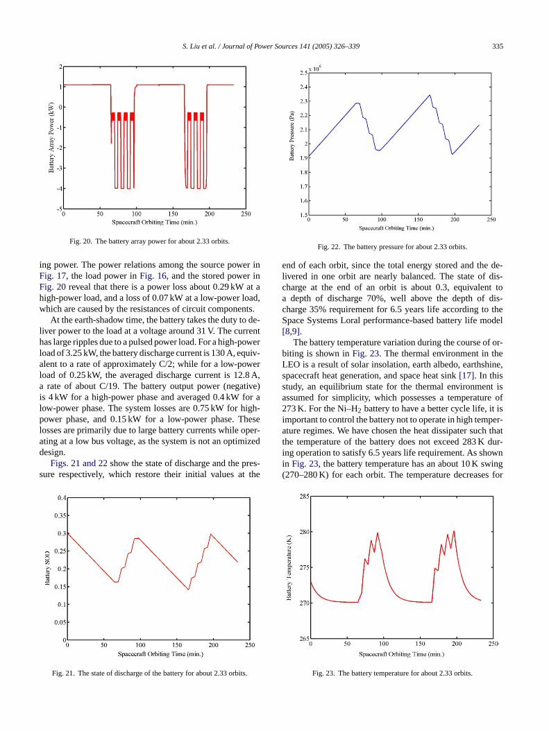
S. Liu et al. / Journal of Power Sources 141 (2005) 326–339 335
Fig. 20. The battery array power for about 2.33 orbits.
ing power. The power relations among the source power inFig. 17, the load power inFig. 16, and the stored power inFig. 20reveal that there is a power loss about 0.29 kW at ahigh-power load, and a loss of 0.07 kW at a low-power load,which are caused by the resistances of circuit components.
At the earth-shadow time, the battery takes the duty to de-liver power to the load at a voltage around 31 V. The currenthas large ripples due to a pulsed power load. For a high-powerload of 3.25 kW, the battery discharge current is 130 A, equiv-alent to a rate of approximately C/2; while for a low-powerload of 0.25 kW, the averaged discharge current is 12.8 A,a rate of about C/19. The battery output power (negative)is 4 kW for a high-power phase and averaged 0.4 kW for alow-power phase. The system losses are 0.75 kW for high-power phase, and 0.15 kW for a low-power phase. Theselosses are primarily due to large battery currents while oper-ating at a low bus voltage, as the system is not an optimizeddesign.
Figs. 21 and 22show the state of discharge and the pres-sure respectively, which restore their initial values at the
.
Fig. 22. The battery pressure for about 2.33 orbits.
end of each orbit, since the total energy stored and the de-livered in one orbit are nearly balanced. The state of dis-charge at the end of an orbit is about 0.3, equivalent toa depth of discharge 70%, well above the depth of dis-charge 35% requirement for 6.5 years life according to theSpace Systems Loral performance-based battery life model[8,9].
The battery temperature variation during the course of or-biting is shown inFig. 23. The thermal environment in theLEO is a result of solar insolation, earth albedo, earthshine,spacecraft heat generation, and space heat sink[17]. In thisstudy, an equilibrium state for the thermal environment isassumed for simplicity, which possesses a temperature of273 K. For the Ni–H2 battery to have a better cycle life, it isimportant to control the battery not to operate in high temper-ature regimes. We have chosen the heat dissipater such thatthe temperature of the battery does not exceed 283 K dur-ing operation to satisfy 6.5 years life requirement. As shownin Fig. 23, the battery temperature has an about 10 K swing(270–280 K) for each orbit. The temperature decreases for
Fig. 21. The state of discharge of the battery for about 2.33 orbits
Fig. 23. The battery temperature for about 2.33 orbits.
336 S. Liu et al. / Journal of Power Sources 141 (2005) 326–339
a charging mode. This is again due to, in addition to theheat transfer, the electrochemical reactions that absorb thereversible heat. During a discharge mode, heat is releasedfrom the both reversible and irreversible processes, causingthe temperature to rise. However, for a low discharge current,the rate of heat dissipation is higher than that of generation,yielding a temporary temperature drop. This is shown by thejagged temperature profile when the spacecraft is in the earthshadow time.
6. Discussion
The present model for the Ni–H2 battery is based on afirst approximation—uniform reactions, no rate and concen-tration limitations, and the two-parameter activity coefficientcharacterization of phase activities. The model allows to pre-dict the battery behaviors and to perform preliminary systemlevel design and analysis under the conditions of a regulatedcharge/discharge protocol. However, like any other models,the present model has several limitations.
The first noticeable limitation is that, as shown inFig. 4,the model does not agree with the data for the dischargebelow 1.15 V. The discharge plateau appeared near 1.15 Vis due to the activity of the�-phase nickel oxyhydroxide,f ientm toredi oft -c reas-i ajorp the� the� nglyt apaci doesn on-v y thed at al easeda n oft y9 esenm rateda con-t cess.O thel ptho har-a etera ino
ver-p es tot cribedi hat
of porous electrodes where most of heat is generated. Thus,the model is prone errors if overcharge, deep discharge, andhigh-rate discharge occur. The error may also result fromfollowing sources. (1) Several thermal effects are ignored inthe model, such as heat due to isometric process, enthalpy ofmixing, phase change and change of specific heat. (2) Thenon-linear feature of overpotential loss is not included. (3)The two-parameter activity coefficient method may also re-sult in discrepancy in reversible heat. These features can beincluded and improved in the future modeling using detailedthermodynamic data, which, unfortunately, are not availableat this time.
Finally, the model does not include capacity fade effect.However, the battery array can be sized based on the SpaceSystems Loral performance-based battery design life model[8,9] using the present model, as explained in Section5. Toensure a safe, reliable and long lifetime, the spacecraft bat-tery discharge rate is controlled not to exceed C/2.0, the dis-charge voltage not to exceed the lower limit of 1.15 V, andthe temperature not to exceed 283 K. The system design canbe improved if a practical load profile is given by utilizing anappropriate bus voltage level and a regulation method, andby optimizing solar array and battery array sizes. Though itis not optimized, the present system still allows performingpreliminary studies of the dynamic behaviors of the Ni–H2b
7
icso andn teryi ratea mpli-fi ther r ac-t pro-c etailso e VTBi lowsf sys-t ndt odeli al re-s ancya . Thef cter-i andt
A
.J.u om-
or which, apparently, the two-parameter activity coefficethod does not characterize very well. The charge s
n the �-phase, according to[4], makes up about 30%he total active material. The conversion to the�-phase ocurs mainly in an overcharge process at a cost of decng the�-phase oxyhydroxide. During discharge, two marallel processes compete: one is the conversion from-phase oxyhydroxide to the hydroxide, the other is from-phase oxyhydroxide to the hydroxide, and both are stro
emperature-dependent and contribute to the discharge cty. On the other hand, charging at high temperaturesot yield a complete oxidation of the hydroxide, which cersely affects the discharge capacities. This is shown bata inFig. 4 that a larger discharge capacity results
ower temperature, and the voltage discrepancy is decrt high temperatures. Without an overcharge, the fractio
he�-phase is less than 10%, whereas the�-phase is nearl0%. Based on this analysis, we can conclude that the prodel best applies to the case in which the battery is opet a low temperature (between 273 and 283 K), and is
rolled such that it does not undergo an overcharge protherwise, the model incurs an error of 30%, for which
ower voltage limit (1.15 V) corresponds to an actual def discharge of about 30%. It is possible in the future to ccterize the phase activities using three- or four-paramctivity coefficients for improving the model behaviorsvercharge and deep discharge regimes.
The thermal modeling mainly considers the constant ootential loss and the reversible heat, which best appli
he case of a controlled charge/discharge scenario desn Section5. The bulk temperature is usually lower than t
-
t
attery in a LEO space environment.
. Conclusion
The Ni–H2 battery model based on the thermodynamf one-electron redox reaction between nickel hydroxideickel oxyhydroxide is established in the VTB. The bat
s assumed uniform throughout, and it is not subject tond concentration dependencies, which allows great sication in mathematical treatment. The non-ideality ofeversible potential is characterized by the two-parameteivity coefficients. The overcharge and the self-dischargeesses are characterized by the oxygen reaction. The df the energy conversion processes are discussed and th
mplementation of the model is presented. The model alor the battery behaviors to be studied in a configurableem while it is dynamically interacting with the system ahe environment. The simulation results show that the mn general has a good agreement with the experimentults above a voltage of 1.15 V, below which the discrepppears if the battery is overcharged prior to discharge
uture research will be devoted to improving the charazation of thermal behaviors, non-linear overpotentials,he phase activities.
cknowledgements
This work was sponsored jointly by Veridian M.Rnder contract 00-MRJ-1085-100, by the US Army C
S. Liu et al. / Journal of Power Sources 141 (2005) 326–339 337
munications and Electronics Command and the NationalReconnaissance Office under contract NRO-00-C-1034.
Appendix A
A.1. Useful expressions
Since the analytical expressions for the potentials of thenickel and oxygen reactions are given (Eq.(5) and (12)), they,together with their derivatives, can be accurately computed.Thus, we will seek expressions for the admittance matrix el-ements expressed in terms of potentials and their derivatives,which are given as:
∂ENi
∂x
= −RT
F
(1
x(1 − x)− 1
2[A0(T )C′(x) + B0(T )D′(x)]
),
(A1)
∂ENi
∂T= e1 + ENi − E0
Ni
T
+ RT
2F[A′
0(T )C(x) + B′0(T )D(x)], (A2)
A
rrenta
i
v
le, itit inu
i
Combining Eq.(A7) and(A8), we have.
va(t) − vc(t) − ENi (t)
Rint
= −Qmax
2h[3x(t) − 4x(t − h) + x(t − 2h)]. (A9)
Eq. (A9) can be solved forx(t) numerically for given ter-minal across variables.
The nickel current component can be derived from Eqs.(5) and(A7). This is,
iNi (t) =∑k
gNi,kk(t) − bNi (t − h), k = va, vc, T, P,
(A10)
where,
gNi,a = 1
Rint + (∂ENi/∂x)/(∂iNi/∂x)|t−h
gNi,c = −gNi,a
gNi,T = − 1
Rint
∂ENi
∂T
∣∣∣∣t−h
gNi,P = 0
, (A11)
licitf ndt
w
∂2ENi
∂T 2= R
F[A′
0(T )C(x) + B′0(T )D(x)], (A3)
∂2ENi
∂x∂T
= −R
F
1
x(1 − x)− 1
2[A0(T )C′(x) + B0(T )D′(x)]
−T
2[A′
0(T )C′(x) + B′0(T )D′(x)]
,
(A4)
dEO2
dT= −0.00168. (A5)
.2. Electrical terminal
The terminal variables can be related to the battery cund voltage as
a(t) = −ic(t) = iNi (t) + iO2(t), (A6)
a(t) − vc(t) = v(t) = ENi (t) + RiiNi (t). (A7)
Since the state of discharge is not a terminal variabs necessary for the device object to computex during eachime step. To do so, Eq.(14)is discretized in the time domasing Gear’s 2[18],
Ni (t) = −Qmax
2h[3x(t) − 4x(t − h) + x(t − 2h)]. (A8)
bNi (t − h) = −iNi (t − h) +∑k
gNi,kk(t − h),
k = va, vc, T, P. (A12)
For the oxygen current component, since it is an expunction of the terminal variables, it is straightforward to fihe standard expression, as given below.
iO2(t) =∑k
gO2,kk(t) − bO2(t − h), k = va, vc, T, P,
(A13)
here,
gO2,a = 4(1− αO2)F
RTiO2
∣∣∣∣t−h
gO2,c = −gO2,a
gO2,T =(
12,025
T 2− 4(1− αO2)
× F
RT 2
(va − vc − EO2+T
dEO2
dT
))iO2
∣∣∣∣t−h
gO2,P = 0
,
(A14)
bO2(t − h) = −iO2(t − h) +∑k
gO2,kk(t − h),
k = va, vc, T, P. (A15)
338 S. Liu et al. / Journal of Power Sources 141 (2005) 326–339
Using(A10) and(A13) in (A6), it can be found the equa-tions for the anode and cathode are,
(ia(t)
ic(t)
)=(
ga,a ga,c ga,T ga,P
gc,a gc,c gc,T gc,P
)va(t)
vc(t)
T (t)
P(t)
−(ba(t − h)
bc(t − h)
), (A16)
where,
ga,a = −gc,c = gNi,a + gO2,a
ga,c = −gc,c = gNi,c + gO2,c
ga,T = −gc,T = gNi,T + gO2,T
ga,P = −gc,P = 0
, (A17)
ba(t − h) = −bc(t − h) = bNi (t − h) + bO2(t − h). (A18)
A.3. Thermal terminal
Construction of the thermal terminal is based on Eq.(16),which can be rearranged, after time-discretizing, as:
icpm
inala
w
g
g
− 1
T
[va − vc − EO2 + T
dEO2
dT
]∂iO2
∂vc+ iO2
T,
(A22)
gT,T = ∂iT
∂T
∣∣∣∣t−h
= − cpm
2hT 2[−4T (t − h) + T (t − 2h)]
+(iNi
T 2− 1
T
∂iNi
∂T
)[va − vc − ENi + T
∂ENi
∂T
]
− iNi
∂2ENi
∂T 2+(iO2
T 2− 1
T
∂iO2
∂T
)
×[va − vc − EO2 + T
dEO2
dT
], (A23)
gT,P = ∂iT
∂P
∣∣∣∣t−h
= 0, (A24)
bT(t − h) = −iT(t − h) +∑k
gT,kk(t − h),
k = va, vc, T, P, (A25)
where,
∂ ∂ENi (∂2ENi/(∂x∂T ))(∂iNi/∂va)
A
d
,
i
w sv inal.TP alc
T(t) =2hT (t)
[3T (t) − 4T (t − h) + T (t − 2h)]
− iNi (t)
T (t)
[va(t) − vc(t) − ENi (t) + T (t)
∂ENi
∂T(t)
]
− iO2(t)
T (t)
[va(t) − vc(t) − EO2(t) + T (t)
∂EO2
∂T(t)
].
(A19)
Thus, we obtain the RC equation for the thermal terms:
iT(t) = (gT,a gT,c gT,T gT,P)
va(t)
vc(t)
T (t)
P(t)
− bT(t − h),
(A20)
here,
T,a = ∂iT
∂va
∣∣∣∣t−h
= − 1
T
[va − vc − ENi + T
∂ENi
∂T
]∂iNi
∂va
− iNi
T
[1 − ∂ENi
∂va+ T
∂
∂va
∂ENi
∂T
]
− 1
T
[va − vc − EO2 + T
dEO
dT
]∂iO2
∂va− iO2
T, (A21)
T,c = ∂iT
∂vc
∣∣∣∣t−h
= − 1
T
[va − vc − ENi + T
∂ENi
∂T
]∂iNi
∂vc
− iNi
T
[−1 − ∂ENi
∂vc+ T
∂
∂vc
∂ENi
∂T
]
∂va ∂T=
∂iNi/∂x, (A26)
∂
∂vc
∂ENi
∂T= (∂2ENi/(∂x∂T ))(∂iNi/∂vc)
∂iNi/∂x(A27)
.4. Pressure signal terminal
The pressure calculation follows Eqs.(17)–(19). A time-iscretized form of the pressure is given as,
p(t) = RT (t)
3Vg
[h
FiNi (t) + 4nH2(t − h) − nH2(t − 2h)
].
(A28)
The equation for the pressure signal terminal follows
P(t) = P(t)
Rp− p(t). (A29)
herep denotes the pressure, whileP signifies the acrosariable.Rp is the output impedance of the pressure termo accurately monitor the pressure, it requiresip(t) ≈ 0 and(t) ≈p(t). Thus,Rp = 1. The RC equation for this terminan be derived as,
iP(t) = (gP,a gP,c gP,T gP,P
)
va(t)
vc(t)
T (t)
P(t)
− bP(t − h)
(A30)
S. Liu et al. / Journal of Power Sources 141 (2005) 326–339 339
where,
gP,a = − h
F
∂iNi
∂va
∣∣∣∣t−h
gP,c = − h
F
∂iNi
∂vc
∣∣∣∣t−h
gP,T = − R
3Vg
[h
FiNi (t) + 4nNi (t − h)
− nNi (t − 2h) + T (t)h
F
∂iNi
∂T
]∣∣∣∣t−h
gP,P = 1
RP= 1
, (A31)
bP(t − h) = −iP(t − h)
+∑k
gP,kk(t − h), k = va, vc, T, P.
(A32)
Combining Eq.(A16), (A20) and(A30) yield Eq.(22).
References
[1] J.D. Dunlop, J. Giner, G. Van Ommering, J.F. Stockel, Nickel Hy-
l-mber
cell,
re-(6)
acityower
[6] P.J. Johnson, S.W. Donley, D.C. Verrier, Orbital simulation life testsof nickel hydrogen batteries with additional non-eclipse cycles, J.Power Sources 76 (1998) 210–214.
[7] S.N. Lvov, D.D. MacDonald, Thermodynamic behavior of Ni–Cdand Ni–H2 batteries over wide ranges of temperatures (0–200◦C),KOH concentrations (0.1–20 mol kg−1) and H2 pressure (0.1–500bar), J. Power Sources 72 (1998) 136–145.
[8] P. Dalton, F. Cohen, International space station nickel-hydrogenbattery on-orbit performance, in: Proceedings of IECEC 2002.37th Intersociety Energy Conversion Engineering Conference, Pa-per #20091, 2002.
[9] P. Dalton, F. Cohen, Update on international space station nickel-hydrogen battery on-orbit performance, in: Proceedings of AIAA2003, Paper #12066, 2003.
[10] R.A. Dougal, C.W. Brice, R.O. Pettus, G. Cokkinides, A.P.S. Me-liopoulos, Virtual prototyping of PCIM systems—the virtual test bed,in: Proceedings of PCIM/HFPC ’98 Conference, Santa Clara, CA,November 1998, pp. 226–234.
[11] M.R. Lightner, S.W. Director, Computer-aided design of electroniccircuits, in: D.G. Fink, D. Christiansen (Eds.), Electronics Engi-neers’ Handbook, 3rd ed., McGraw-Hill, New York, 1989, Section27.
[12] M. Jain, A.L. Elmore, M.A. Mathews, J.W. Weidner, Thermody-namic consideration of the reversible potential for the nickel elec-trode, Electrochem. Acta 43 (18) (1998) 2649–2660.
[13] K.P. Ta, J. Newman, Proton intercalation hysteresis in charging anddischarging nickel hydroxide electrodes, J. Electrochem. Soc. 146(8) (1999) 2769–2779.
[14] V. Srinvasan, J.W. Weidner, J. Newman, Hysteresis during cyclingof nickel hydroxide active material, J. Electrochem. Soc. 148 (9)
[ ance.
[[ e en-
sults,
[ tial
drogen Cell, U.S. Patent 3867299, 1975.[2] J.D. Dunlop, G.M. Rao, T.Y. Yi, NASA Handbook for Nicke
Hydrogen Batteries, NASA Reference Pub. 1314, Septe1993.
[3] B. Wu, R.E. White, Self-discharge model of a nickel-hydrogenJ. Electrochem. Soc. 147 (3) (2000) 902–909.
[4] B. Wu, R.E. White, Modeling of a nickel-hydrogen cell, phaseaction in the nickel active material, J. Electrochem. Soc. 148(2001) A595–A609.
[5] H. Vaidyanathan, H. Wajsgras, G.M. Rao, Voltage and capstability of the hubble telescope nickel-hydrogen battery, J. PSources 58 (1995) 7–14.
(2001) A969–A980.15] D. Bernardi, E. Pawlikowski, J. Newman, A general energy bal
for battery systems, J. Electrochem. Soc. 132 (1) (1985) 5–1216] VTB Model Library. http://vtb.engr.sc.edu/.17] A.J. Juhasz, An analysis and procedure for determining spac
vironmental sink temperatures with selected computational reNASA/TM-2001-210063, January 2001.
18] C.W. Gear, Numerical Initial Value Problems in Ordinary DifferenEquations, Prentice-Hall, Englewood Cliffs, NJ, 1971.