Embed Size (px)
Citation preview
Lee MasonGlenn Research Center, Cleveland, Ohio
Chad CarmichaelSaint Louis University, St. Louis, Missouri
A Small Fission Power System With Stirling Power Conversion for NASA Science Missions
NASA/TM—2011-217204
December 2011
NETS–2011–3326
https://ntrs.nasa.gov/search.jsp?R=20120001793 2018-06-30T09:52:24+00:00Z
NASA STI Program . . . in Profi le
Since its founding, NASA has been dedicated to the advancement of aeronautics and space science. The NASA Scientifi c and Technical Information (STI) program plays a key part in helping NASA maintain this important role.
The NASA STI Program operates under the auspices of the Agency Chief Information Offi cer. It collects, organizes, provides for archiving, and disseminates NASA’s STI. The NASA STI program provides access to the NASA Aeronautics and Space Database and its public interface, the NASA Technical Reports Server, thus providing one of the largest collections of aeronautical and space science STI in the world. Results are published in both non-NASA channels and by NASA in the NASA STI Report Series, which includes the following report types: • TECHNICAL PUBLICATION. Reports of
completed research or a major signifi cant phase of research that present the results of NASA programs and include extensive data or theoretical analysis. Includes compilations of signifi cant scientifi c and technical data and information deemed to be of continuing reference value. NASA counterpart of peer-reviewed formal professional papers but has less stringent limitations on manuscript length and extent of graphic presentations.
• TECHNICAL MEMORANDUM. Scientifi c
and technical fi ndings that are preliminary or of specialized interest, e.g., quick release reports, working papers, and bibliographies that contain minimal annotation. Does not contain extensive analysis.
• CONTRACTOR REPORT. Scientifi c and
technical fi ndings by NASA-sponsored contractors and grantees.
• CONFERENCE PUBLICATION. Collected papers from scientifi c and technical conferences, symposia, seminars, or other meetings sponsored or cosponsored by NASA.
• SPECIAL PUBLICATION. Scientifi c,
technical, or historical information from NASA programs, projects, and missions, often concerned with subjects having substantial public interest.
• TECHNICAL TRANSLATION. English-
language translations of foreign scientifi c and technical material pertinent to NASA’s mission.
Specialized services also include creating custom thesauri, building customized databases, organizing and publishing research results.
For more information about the NASA STI program, see the following:
• Access the NASA STI program home page at http://www.sti.nasa.gov
• E-mail your question via the Internet to help@
sti.nasa.gov • Fax your question to the NASA STI Help Desk
at 443–757–5803 • Telephone the NASA STI Help Desk at 443–757–5802 • Write to:
NASA Center for AeroSpace Information (CASI) 7115 Standard Drive Hanover, MD 21076–1320
Lee MasonGlenn Research Center, Cleveland, Ohio
Chad CarmichaelSaint Louis University, St. Louis, Missouri
A Small Fission Power System With Stirling Power Conversion for NASA Science Missions
NASA/TM—2011-217204
December 2011
NETS–2011–3326
National Aeronautics andSpace Administration
Glenn Research CenterCleveland, Ohio 44135
Prepared for theNuclear and Emerging Technologies for Space (NETS-2011)sponsored by the ANS Aerospace Nuclear Science and Technology Division, the ANS Trinity Section, and the American Institute of Aeronautics and AstronauticsAlbuquerque, New Mexico, February 7–10, 2011
Acknowledgments
The authors wish to acknowledge the contribution of Barry Penswick who helped in developing the Stirling module confi guration. The foundation of this study is the original study conducted by the National Aeronautics and Space Administration (NASA) and Department of Energy team in early 2010 resulting in the 1-kWe small fi ssion power system with thermoelectric conversion. That team developed an extremely innovative concept to address a serious gap in spacecraft power systems for fl agship-class NASA science missions. Key members of the original study team were Jim Werner, Dave Poston, Lou Qualls, Ron Lipinski, Mike Houts, John Elliott, Bill Nesmith, Duncan MacPherson, Sterling Bailey, and Abe Weitzberg. Special thanks go to the sponsors of the original study: John Casani and Heidi Hammel from the Decadal Survey Giant Planets Panel, Len Dudzinski from the NASA Science Mission Directorate, and John Hamley from the Radioisotope Power Systems Program Offi ce.
Available from
NASA Center for Aerospace Information7115 Standard DriveHanover, MD 21076–1320
National Technical Information Service5301 Shawnee Road
Alexandria, VA 22312
Available electronically at http://www.sti.nasa.gov
Trade names and trademarks are used in this report for identifi cation only. Their usage does not constitute an offi cial endorsement, either expressed or implied, by the National Aeronautics and
Space Administration.
Level of Review: This material has been technically reviewed by technical management.
This report contains preliminary fi ndings, subject to revision as analysis proceeds.
NASA/TM—2011-217204 1
A Small Fission Power System With Stirling Power Conversion for NASA Science Missions
Lee Mason
National Aeronautics and Space Administration Glenn Research Center Cleveland, Ohio 44135
Chad Carmichael
Saint Louis University St. Louis, Missouri 63103
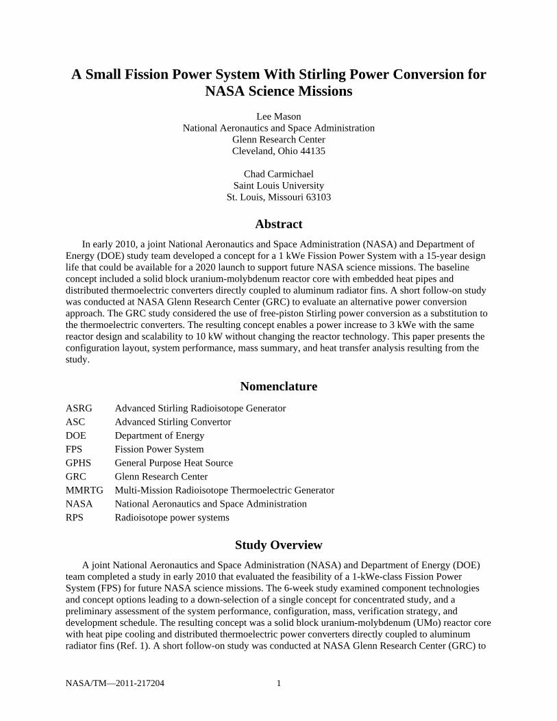
Abstract
In early 2010, a joint National Aeronautics and Space Administration (NASA) and Department of Energy (DOE) study team developed a concept for a 1 kWe Fission Power System with a 15-year design life that could be available for a 2020 launch to support future NASA science missions. The baseline concept included a solid block uranium-molybdenum reactor core with embedded heat pipes and distributed thermoelectric converters directly coupled to aluminum radiator fins. A short follow-on study was conducted at NASA Glenn Research Center (GRC) to evaluate an alternative power conversion approach. The GRC study considered the use of free-piston Stirling power conversion as a substitution to the thermoelectric converters. The resulting concept enables a power increase to 3 kWe with the same reactor design and scalability to 10 kW without changing the reactor technology. This paper presents the configuration layout, system performance, mass summary, and heat transfer analysis resulting from the study.
Nomenclature
ASRG Advanced Stirling Radioisotope Generator ASC Advanced Stirling Convertor DOE Department of Energy FPS Fission Power System GPHS General Purpose Heat Source GRC Glenn Research Center MMRTG Multi-Mission Radioisotope Thermoelectric Generator NASA National Aeronautics and Space Administration RPS Radioisotope power systems
Study Overview
A joint National Aeronautics and Space Administration (NASA) and Department of Energy (DOE) team completed a study in early 2010 that evaluated the feasibility of a 1-kWe-class Fission Power System (FPS) for future NASA science missions. The 6-week study examined component technologies and concept options leading to a down-selection of a single concept for concentrated study, and a preliminary assessment of the system performance, configuration, mass, verification strategy, and development schedule. The resulting concept was a solid block uranium-molybdenum (UMo) reactor core with heat pipe cooling and distributed thermoelectric power converters directly coupled to aluminum radiator fins (Ref. 1). A short follow-on study was conducted at NASA Glenn Research Center (GRC) to
NASA/TM—2011-217204 2
evaluate an alternative power conversion approach. The goal was to utilize the same UMo heat pipe reactor, but replace the thermoelectric power conversion with free-piston Stirling converters. The study products included a preliminary system layout, mass summary, performance assessment, and heat transfer analysis.
Reactor Concept
The Stirling-based system utilizes the same reactor design developed for the 1-kWe thermoelectric system. The reactor uses 93 percent enriched block UMo fuel surrounded by a beryllium reflector with a single, centered boron-carbide control rod. The compact, fast-spectrum core is 12.9 cm in diameter by 30 cm long and is cooled by eighteen 1.1-cm-diameter superalloy-clad, sodium heat pipes. The radial reflector is 7.7 cm thick. The upper axial reflector is 5 cm thick and the lower axial reflector, on the shield side, is 7 cm thick. The average fuel temperature is approximately 1200 K and the heat pipe condenser temperature is 1100 K. The reactor nominal power output is 13 kWt, with operating margins that could permit a two-fold thermal power increase without any design change. A lithium hydride and tungsten shadow shield reduces the reactor-induced radiation to less than 1.0×10¹¹ n/cm2 and 25 krad gamma at a 10 m separation distance within a 4.5-m-diameter payload envelope. This allows the use of commercially available electronics for the spacecraft bus.
The reactor is designed to remain subcritical during launch processing and under postulated launch accidents. After the spacecraft is placed on an appropriate trajectory, startup is initiated through an Earth-commanded withdrawal of the control rod through a series of motor-driven steps to achieve full power. Once at full power, the reactor is self-regulating based on negative temperature reactivity feedback control where the reactor thermal power automatically decreases in response to a temperature increase, and increases in response to a reactor temperature decrease. The reactor is designed for a full-power life of 15 years with less than 1 percent fuel burnup. A gradual drop in reactor temperature (~3 K/year) will occur over the 15-year life due to the fuel burnup, resulting in a decrease in system output power of about 5 percent at end of life. This could be compensated by a periodic control rod adjustment, if deemed necessary. The reactor design is considered fairly mature using relatively conventional fuel and materials. While heat pipes have never been used as the primary cooling method in a nuclear reactor, the compact size and low power rating of this design should simplify the development process. A 2020 launch availability was projected for the original design concept, allowing 10 years for development and qualification. The substitution of free-piston Stirling power conversion should not appreciably affect this estimate.
Stirling Power Conversion Approach
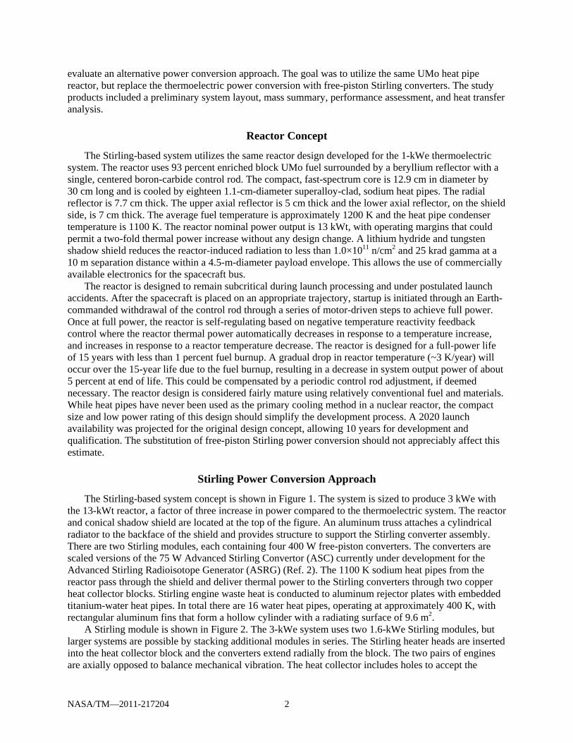
The Stirling-based system concept is shown in Figure 1. The system is sized to produce 3 kWe with the 13-kWt reactor, a factor of three increase in power compared to the thermoelectric system. The reactor and conical shadow shield are located at the top of the figure. An aluminum truss attaches a cylindrical radiator to the backface of the shield and provides structure to support the Stirling converter assembly. There are two Stirling modules, each containing four 400 W free-piston converters. The converters are scaled versions of the 75 W Advanced Stirling Convertor (ASC) currently under development for the Advanced Stirling Radioisotope Generator (ASRG) (Ref. 2). The 1100 K sodium heat pipes from the reactor pass through the shield and deliver thermal power to the Stirling converters through two copper heat collector blocks. Stirling engine waste heat is conducted to aluminum rejector plates with embedded titanium-water heat pipes. In total there are 16 water heat pipes, operating at approximately 400 K, with rectangular aluminum fins that form a hollow cylinder with a radiating surface of 9.6 m2.
A Stirling module is shown in Figure 2. The 3-kWe system uses two 1.6-kWe Stirling modules, but larger systems are possible by stacking additional modules in series. The Stirling heater heads are inserted into the heat collector block and the converters extend radially from the block. The two pairs of engines are axially opposed to balance mechanical vibration. The heat collector includes holes to accept the
NASA/TM—2011-217204 3
sodium heat pipes from the reactor. The reactor heat pipe condenser length is long enough to deliver thermal power to two heat collector blocks in series, resulting in an average Stirling heater head temperature of 950 K. The rejector plate forms a rectangular collar around each Stirling cold-side rejector, resulting in a rejector temperature of about 480 K. The projected Stirling converter efficiency with these interface temperatures is about 27 percent. The rejector plates include holes for four water heat pipes that carry the waste heat to the radiator fins, and the heat pipe evaporator length is sized for two adjoined Stirling modules. The mass of a Stirling module (without heat pipes) is estimated at about 54 kg including the four Stirling converters at 5 kg each. Each 1.6-kWe Stirling module would require a 15-kg electrical controller that provides alternating current (ac) to direct current (dc) conversion and 28 Vdc bus voltage regulation. After thermal insulation losses at the hot end and electrical losses in the controller, the net efficiency is about 23 percent.
The overall system mass is presented in Table 1. The total system mass (without margin) is estimated at 750 kg, or about 4 W/kg. The mass of the reactor core, shield, and instrumentation and control assemblies is the same as estimated for the thermoelectric system, since those elements are unchanged. The reactor heat pipe assembly mass is less because the sodium heat pipe length is reduced from 4 to less than 2 m with the Stirling option. The power conversion assembly includes the two Stirling modules and their respective electrical controllers. The radiator assembly consists of the 16 water heat pipes, each with an aluminum condenser fin. The truss assembly mass is based on aluminum tubing between the shield and radiator and an aluminum frame to support the cylindrical radiator.
Figure 2.—1.6-kWe Stirling module concept.
Figure 1.—3-kWe Stirling fission power concept.
TABLE 1.—3-KWE SYSTEM MASS ESTIMATE Current best estimate,
(kg) Core assembly 133 Heat pipe assembly 10 Shield assembly 271 Power conversion assembly 138 Radiator assembly 106 Truss assembly 60 Inst. and control assembly 32 Total FPS 750
(4.0 W/kg)
NASA/TM—2011-217204 4
System Comparisons
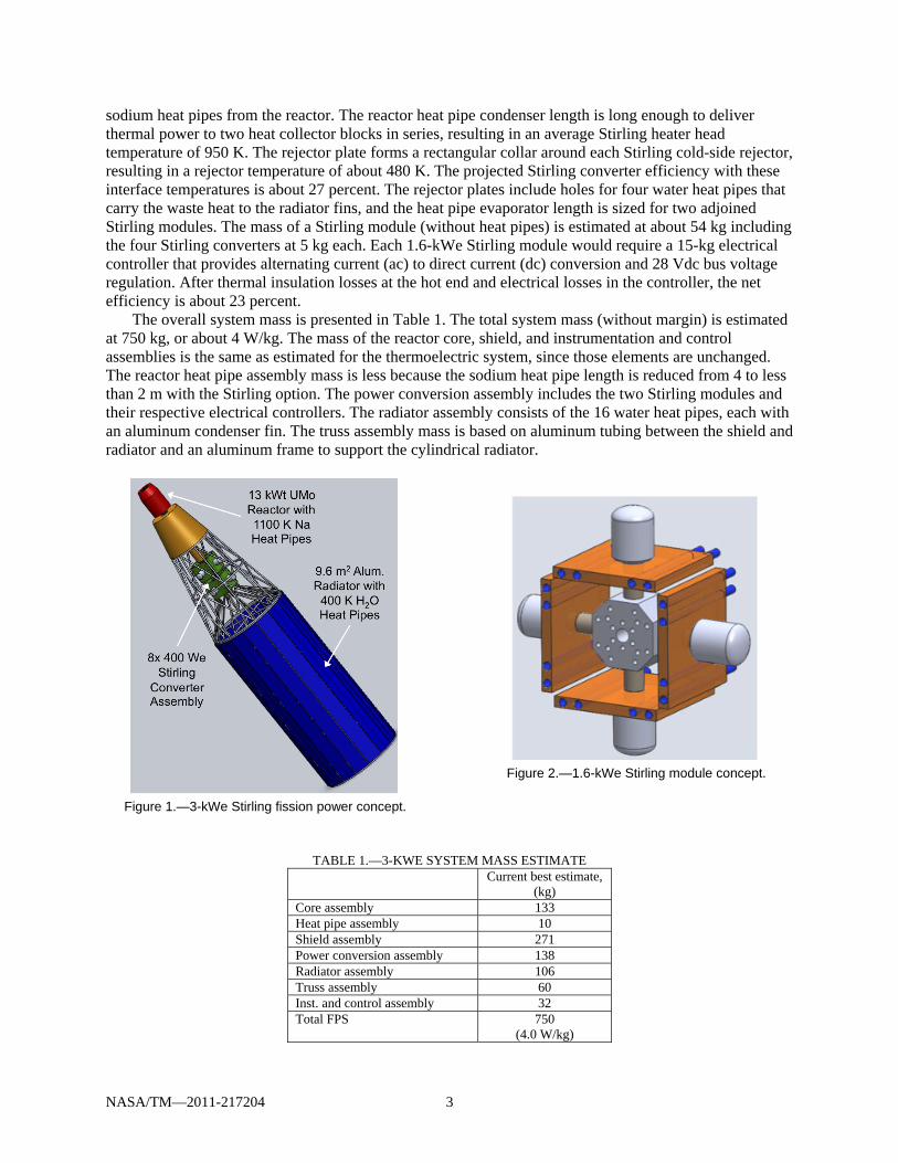
A small FPS using the solid fuel, heat pipe reactor provides a competitive option for NASA missions that require 1 kWe up to about 10 kWe. Since the reactor and shield mass does not decrease appreciably for power levels below 1 kWe, the system mass does not compare favorably with other options, such as radioisotope power systems (RPS). Above 10 kWe, the fission system would benefit from an alternative reactor design approach, such as fuel pins instead of block fuel and pumped liquid-metal coolant instead of heat pipes. Figure 3 shows the system mass and specific power of thermoelectric- and Stirling-based FPS for power levels between 0.5 and 10 kWe utilizing the UMo heat pipe reactor approach. The system mass comprises the reactor, shield, and balance-of-plant (including the power conversion, radiators, and truss structure). In the cases presented, the shield mass varies based on the reactor thermal power, assuming the 10 m separation and dose limits mentioned previously. The mass associated with the balance-of-plant scales predominantly with electrical power output.
For the thermoelectric systems, the same reactor design could be used for systems up to about 1.5 kWe. Above 1.5 kWe, the reactor physical dimensions would be modified, but the basic technical approach could be retained. A 1-kWe thermoelectric-based FPS has a mass of 604 kg (without margin) and a specific power of 1.7 W/kg. The 1.5-kWe system, utilizing the same reactor, would have a specific power of 2.1 W/kg. The 3-kWe version would require dimensional changes to the reactor to produce the required 39 kWt and achieve a system-specific power of 2.6 W/kg. Above 3 kWe, an alternative reactor approach may be more practical for the thermoelectric-based systems.
The Stirling systems could use the same reactor up to about 5 kWe, after which the reactor design would require dimensional changes for higher thermal power output. The 3-kWe Stirling system at 750 kg and 4 W/kg is the primary subject of this paper. The 5-kWe system, utilizing the same reactor, has a specific power of 5 W/kg. With slight modifications to the reactor to produce 43 kWt, a 10-kWe system with a specific power of 5.9 W/kg is possible. Other reactor approaches should be considered for Stirling-based systems above 10 kWe, such as the concepts developed for the NASA/DOE Fission Surface Power project (Ref. 3).
Figure 3.—Small fission power system mass comparison.
NASA/TM—2011-217204 5
As shown by the grey arrows on the right axis, the Multi-Mission Radioisotope Thermoelectric Generator (MMRTG) has a specific power of 2.4 W/kg and the Advanced Stirling Radioisotope Generator (ASRG) has a specific power of 5.6 W/kg. While the RPS options offer attractive specific power as compared to their fission counterparts, they are not able to achieve the higher power levels. The current designs are aimed at 110 and 140 W, respectively, for the MMRTG and ASRG, and previous RPS designs, such as the General Purpose Heat Source (GPSH) RTG, have not exceeded 300 W. A major constraint is the availability and cost of the plutonium-238 (Pu-238) fuel. The United States does not have a current capability to produce Pu-238 so the material must be purchased from foreign sources. Conversely, the uranium-235 fuel planned for the small FPS is readily available from DOE.
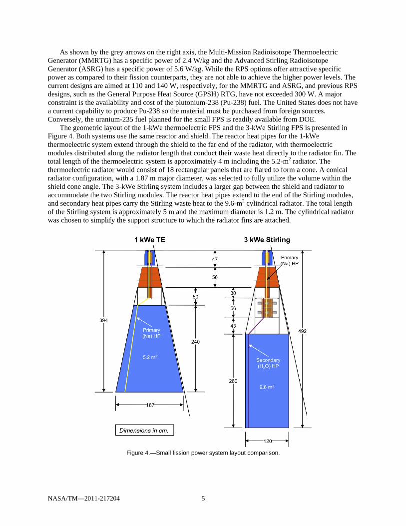
The geometric layout of the 1-kWe thermoelectric FPS and the 3-kWe Stirling FPS is presented in Figure 4. Both systems use the same reactor and shield. The reactor heat pipes for the 1-kWe thermoelectric system extend through the shield to the far end of the radiator, with thermoelectric modules distributed along the radiator length that conduct their waste heat directly to the radiator fin. The total length of the thermoelectric system is approximately 4 m including the 5.2-m2 radiator. The thermoelectric radiator would consist of 18 rectangular panels that are flared to form a cone. A conical radiator configuration, with a 1.87 m major diameter, was selected to fully utilize the volume within the shield cone angle. The 3-kWe Stirling system includes a larger gap between the shield and radiator to accommodate the two Stirling modules. The reactor heat pipes extend to the end of the Stirling modules, and secondary heat pipes carry the Stirling waste heat to the 9.6-m2 cylindrical radiator. The total length of the Stirling system is approximately 5 m and the maximum diameter is 1.2 m. The cylindrical radiator was chosen to simplify the support structure to which the radiator fins are attached.
Figure 4.—Small fission power system layout comparison.
NASA/TM—2011-217204 6
Heat Transfer Analysis
A thermal analysis was needed to ascertain the expected temperatures at the Stirling module interfaces, which led to analytical projections of Stirling conversion efficiency and overall system performance. The thermal analysis was completed under a NASA summer internship by Chad Carmichael from Saint Louis University. The overall Stirling configuration, as shown in Figure 1, was developed in SolidWorks. This led to designs for the individual heat transfer components including the heat collector block, rejector plate, and radiator fin. These components were then subjected to a heat transfer analysis using ANSYS. The construction materials, physical dimensions, and thermal interfaces were adjusted until a satisfactory solution was obtained.
Heat Collector Block
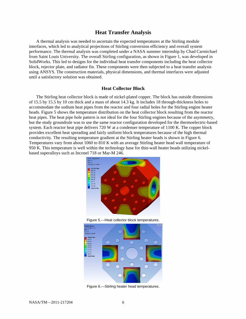
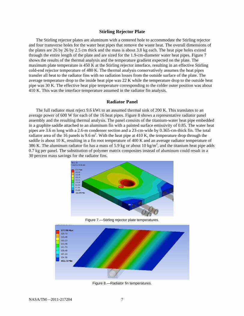
The Stirling heat collector block is made of nickel-plated copper. The block has outside dimensions of 15.5 by 15.5 by 10 cm thick and a mass of about 14.3 kg. It includes 18 through-thickness holes to accommodate the sodium heat pipes from the reactor and four radial holes for the Stirling engine heater heads. Figure 5 shows the temperature distribution on the heat collector block resulting from the reactor heat pipes. The heat pipe hole pattern is not ideal for the four Stirling engines because of the asymmetry, but the study groundrule was to use the same reactor configuration developed for the thermoelectric-based system. Each reactor heat pipe delivers 720 W at a condenser temperature of 1100 K. The copper block provides excellent heat spreading and fairly uniform block temperatures because of the high thermal conductivity. The resulting temperature gradient at the Stirling heater heads is shown in Figure 6. Temperatures vary from about 1060 to 810 K with an average Stirling heater head wall temperature of 950 K. This temperature is well within the technology base for thin-wall heater heads utilizing nickel-based superalloys such as Inconel 718 or Mar-M 246.
Figure 5.—Heat collector block temperatures.
Figure 6.—Stirling heater head temperatures.
NASA/TM—2011-217204 7
Stirling Rejector Plate
The Stirling rejector plates are aluminum with a centered hole to accommodate the Stirling rejector and four transverse holes for the water heat pipes that remove the waste heat. The overall dimensions of the plates are 26 by 26 by 2.5 cm thick and the mass is about 3.8 kg each. The heat pipe holes extend through the entire length of the plate and are sized for the 1.9-cm-diameter water heat pipes. Figure 7 shows the results of the thermal analysis and the temperature gradient expected on the plate. The maximum plate temperature is 450 K at the Stirling rejector interface, resulting in an effective Stirling cold-end rejector temperature of 480 K. The thermal analysis conservatively assumes the heat pipes transfer all heat to the radiator fins with no radiation losses from the outside surface of the plate. The average temperature drop to the inside heat pipe was 22 K while the temperature drop to the outside heat pipe was 30 K. The effective heat pipe temperature corresponding to the colder outer position was about 410 K. This was the interface temperature assumed in the radiator fin analysis.
Radiator Panel
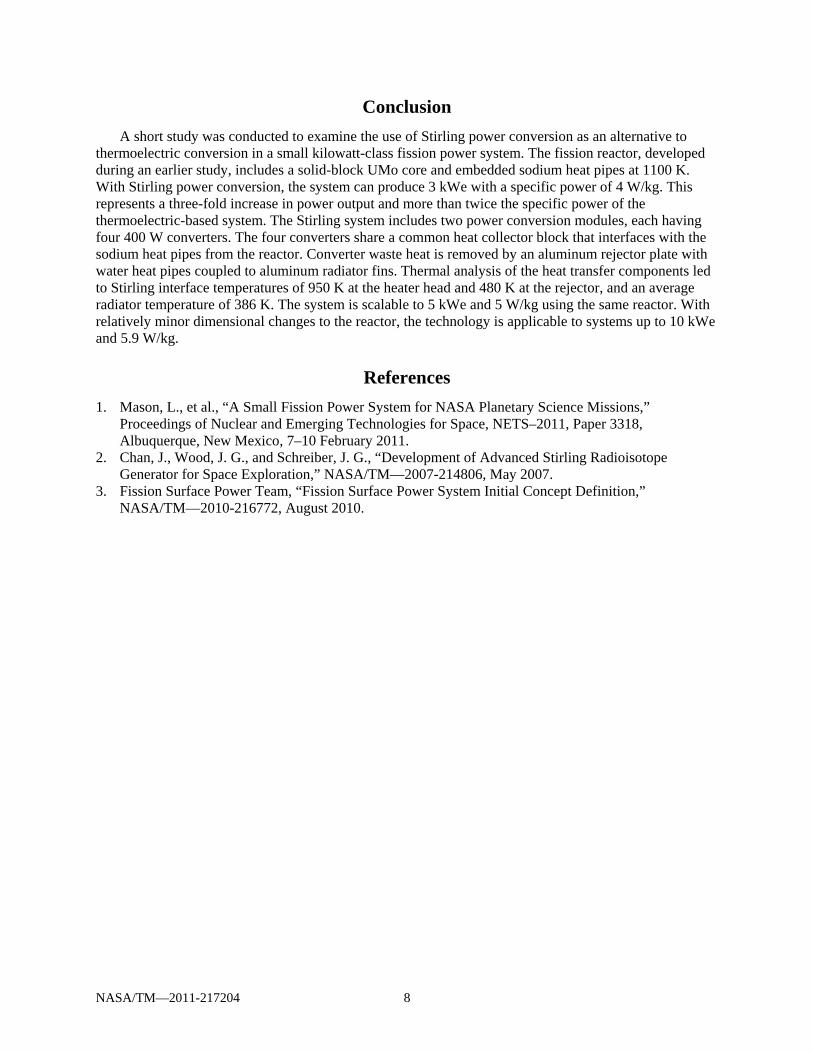
The full radiator must reject 9.6 kWt to an assumed thermal sink of 200 K. This translates to an average power of 600 W for each of the 16 heat pipes. Figure 8 shows a representative radiator panel assembly and the resulting thermal analysis. The panel consists of the titanium-water heat pipe embedded in a graphite saddle attached to an aluminum fin with a painted surface emissivity of 0.85. The water heat pipes are 3.6 m long with a 2.6-m condenser section and a 23-cm-wide by 0.365-cm-thick fin. The total radiator area of the 16 panels is 9.6 m2. With the heat pipe at 410 K, the temperature drop through the saddle is about 10 K, resulting in a fin root temperature of 400 K and an average radiator temperature of 386 K. The aluminum radiator fin has a mass of 5.9 kg or about 10 kg/m2, and the titanium heat pipe adds 0.7 kg per panel. The substitution of polymer matrix composites instead of aluminum could result in a 30 percent mass savings for the radiator fins.
Figure 7.—Stirling rejector plate temperatures.
Figure 8.—Radiator fin temperatures.
NASA/TM—2011-217204 8
Conclusion
A short study was conducted to examine the use of Stirling power conversion as an alternative to thermoelectric conversion in a small kilowatt-class fission power system. The fission reactor, developed during an earlier study, includes a solid-block UMo core and embedded sodium heat pipes at 1100 K. With Stirling power conversion, the system can produce 3 kWe with a specific power of 4 W/kg. This represents a three-fold increase in power output and more than twice the specific power of the thermoelectric-based system. The Stirling system includes two power conversion modules, each having four 400 W converters. The four converters share a common heat collector block that interfaces with the sodium heat pipes from the reactor. Converter waste heat is removed by an aluminum rejector plate with water heat pipes coupled to aluminum radiator fins. Thermal analysis of the heat transfer components led to Stirling interface temperatures of 950 K at the heater head and 480 K at the rejector, and an average radiator temperature of 386 K. The system is scalable to 5 kWe and 5 W/kg using the same reactor. With relatively minor dimensional changes to the reactor, the technology is applicable to systems up to 10 kWe and 5.9 W/kg.
References
1. Mason, L., et al., “A Small Fission Power System for NASA Planetary Science Missions,” Proceedings of Nuclear and Emerging Technologies for Space, NETS–2011, Paper 3318, Albuquerque, New Mexico, 7–10 February 2011.
2. Chan, J., Wood, J. G., and Schreiber, J. G., “Development of Advanced Stirling Radioisotope Generator for Space Exploration,” NASA/TM—2007-214806, May 2007.
3. Fission Surface Power Team, “Fission Surface Power System Initial Concept Definition,” NASA/TM—2010-216772, August 2010.
REPORT DOCUMENTATION PAGE Form Approved OMB No. 0704-0188
The public reporting burden for this collection of information is estimated to average 1 hour per response, including the time for reviewing instructions, searching existing data sources, gathering and maintaining the data needed, and completing and reviewing the collection of information. Send comments regarding this burden estimate or any other aspect of this collection of information, including suggestions for reducing this burden, to Department of Defense, Washington Headquarters Services, Directorate for Information Operations and Reports (0704-0188), 1215 Jefferson Davis Highway, Suite 1204, Arlington, VA 22202-4302. Respondents should be aware that notwithstanding any other provision of law, no person shall be subject to any penalty for failing to comply with a collection of information if it does not display a currently valid OMB control number. PLEASE DO NOT RETURN YOUR FORM TO THE ABOVE ADDRESS.
1. REPORT DATE (DD-MM-YYYY) 01-12-2011
2. REPORT TYPE Technical Memorandum
3. DATES COVERED (From - To)
4. TITLE AND SUBTITLE A Small Fission Power System With Stirling Power Conversion for NASA Science Missions
5a. CONTRACT NUMBER
5b. GRANT NUMBER
5c. PROGRAM ELEMENT NUMBER
6. AUTHOR(S) Mason, Lee; Carmichael, Chad
5d. PROJECT NUMBER
5e. TASK NUMBER
5f. WORK UNIT NUMBER WBS 463169.04.03.01.02
7. PERFORMING ORGANIZATION NAME(S) AND ADDRESS(ES) National Aeronautics and Space Administration John H. Glenn Research Center at Lewis Field Cleveland, Ohio 44135-3191
8. PERFORMING ORGANIZATION REPORT NUMBER E-17607
9. SPONSORING/MONITORING AGENCY NAME(S) AND ADDRESS(ES) National Aeronautics and Space Administration Washington, DC 20546-0001
10. SPONSORING/MONITOR'S ACRONYM(S) NASA
11. SPONSORING/MONITORING REPORT NUMBER NASA/TM-2011-217204
12. DISTRIBUTION/AVAILABILITY STATEMENT Unclassified-Unlimited Subject Category: 20 Available electronically at http://www.sti.nasa.gov This publication is available from the NASA Center for AeroSpace Information, 443-757-5802
13. SUPPLEMENTARY NOTES
14. ABSTRACT In early 2010, a joint National Aeronautics and Space Administration (NASA) and Department of Energy (DOE) study team developed a concept for a 1 kWe Fission Power System with a 15-year design life that could be available for a 2020 launch to support future NASA science missions. The baseline concept included a solid block uranium-molybdenum reactor core with embedded heat pipes and distributed thermoelectric converters directly coupled to aluminum radiator fins. A short follow-on study was conducted at NASA Glenn Research Center (GRC) to evaluate an alternative power conversion approach. The GRC study considered the use of free-piston Stirling power conversion as a substitution to the thermoelectric converters. The resulting concept enables a power increase to 3 kWe with the same reactor design and scalability to 10 kW without changing the reactor technology. This paper presents the configuration layout, system performance, mass summary, and heat transfer analysis resulting from the study.15. SUBJECT TERMS Space power; Fission power systems; Space reactor; Free-piston Stirling
16. SECURITY CLASSIFICATION OF: 17. LIMITATION OF ABSTRACT UU
18. NUMBER OF PAGES
14
19a. NAME OF RESPONSIBLE PERSON STI Help Desk (email:[email protected])
a. REPORT U
b. ABSTRACT U
c. THIS PAGE U
19b. TELEPHONE NUMBER (include area code) 443-757-5802
Standard Form 298 (Rev. 8-98)Prescribed by ANSI Std. Z39-18