Embed Size (px)
Citation preview

A software aid to the design of AGV systems
T C. E. CHENGt
Department of Engtneermg Productton, Untverstty of Technology, Loughborough, England
This paper describes a software aid to assist in- dustrial designers in the design and evaluation of automatic guided vehicle (AGV) systems operating in a flexible manufacturing environment. It is a micro-computer based software and the source program is written in PASCAL so as to provide a rapid and cost effective means for FMS design.
INTRODUCTION
Faced with the problems of intensified competition, strmgent quahty reqmrements and shrinking profit margins, manufacturers are compelled to look for means to improve productwlty, and hence profitability In recent years, flexible manufacturing systems (FMS) have been widely preached and gradually accepted as one of the most promising solutions to the problem of productwlty Im- provement In brief, FMS are a collection of numerically- controlled machine tools, computers and automated material handhng systems Their aim is to transform the economies of scale o f mass production to the economies of scope of batch production so as to improve the latter's efficiency while at the same time retain its flexibility with respect to product variety
At the heart of an FMS Is an automated materml handhng system Its malor requirement ~s to move palletlsed parts m the FMS from one work station to the next m accordance with the part routmgs under the direc- tion and control of a host computer A noticeable feature of the automated material handling system ~s its capability to accept different parts at different part volumes and in random order This makes the FMS slgmficantly different from the conventional transfer hne which is primarily designed to transfer a single part type to the machine tools m a rigid sequence Other functions of the materml handhng system may include the provision of storage space for semi-finished parts, such as m-process buffer stocks at machine tools and loading/unloading of parts on to and from the machine tools before and after processing
Whale there are numerous types of material handhng systems e g roller conveyors, conveyor-belts, overhead monorad conveyors and fork hft trucks, the automatic graded vehicle (AGV) systems are one of the most popular and they have been widely implemented m FMS Basically,
Accepted July 1984 Discussion closes December 1984
Now at Department of Industrial and Systems Engineering, National Umverslty of Singapore, Singapore
an AGV system consists of battery-driven drwerless trucks and a traffic system The latter is a network of guidance wires buried beneath the shop floor and it is supphed with high frequency current responsible for the lnductwe steer- mg of the trucks The trucks are equipped with traffic signal sensors which are used to pick up the control com- mands transmitted from the central computer via the guidance wires In addition, on-board micro-processors provide instant processing of the commands to provide real- time control of the movement of the trucks The AGV system has the combined benefits of being relatively simple to install whilst also being capable of reacting instantly to fluctuations In machine capacity, changes in part operations and partial stoppages of machine tools
For an FMS to function efficiently, control software has to be supphed winch is intended to control the organlsatlon and operation of the system hardware for production There is a hlerarcincal structure of the control software of the FMS At the highest level is the production control software which is used to construct an initial feasible production plan, taking account of the production require- ments and the capabilities and hmltatlons of the FMS With a production plan established, the next level of control IS the selection of the appropriate machine tools and the associated cutting tools from among the alternatives winch can perform the necessary machining operations for each processing stage of each part In addition, the control software has to determine the loading sequence of parts on each selected machine tool Finally, at the lowest level of control is the selection of transport devices which takes as ~ts input the outcomes of the higher levels of control, as the movement of parts in the FMS is determined by the schedules of machining parts Therefore, ff the AGV system is used as the means of transporting parts, the control software should be designed to make decisions on selecting an appropriate truck among the candidate trucks winch can carry the part and transport it to its next designated macinne tool
Thas research is part of a large research project with the aim ot developing a commercmlly available micro-computer based computer package to assist industrial designers in the design and evaluation of FMS The primary objective of the present research ~s to develop a control software for the AGV system in FMS In theory, the control software can be designed to optlmise the performance of the AGV system by means of either mathematical programming (e g integer programming) or &rect enumeration (e g branch-and-bound method) However, due to the com- plexity of the scheduhng problem, it is Impossible to find an optimal solution for a large scale problem because of the proinbitwe computational requirements We, therefore,
0141-1195/84/040204-04 $2 O0 204 Adv Eng Software, 1984, Vol 6, No 4 © 1984 CML Pubhcatlons

Inltializatxon
1 \
W °~rk~ tatlon ] lle~
r\ / AGV Allocatxon Logxc }
Output Proeeaaj
Dtagram 1 A schematw diagram of the relationships among the elements of the software
adopted a heurlsUc approach by applying a decision rule to obtain a good feasible solutmn for a large scale problem m a practical sense
SOFTWARE DESIGN
The AGV system control software is basically composed of five elements (1) the mmahsatmn process, (2) the AGV file, (3) the work statxon file, (4) the AGV allocation logic, and (5) the output process A schemauc dmgram of the relatmnshlps among the various elements of the AGV system software is depicted m Diagram 1 In the following paragraphs, we shall describe m detad the structures, the operating logic and the data reqmrements of each of the elements.
THE INITIALISATION PROCESS
The AGV system- to be analysed is assumed to have a layout as the one shown in Dmgram 2 The maul charac- teristic of the layout is that the machine tools are placed on both sades of a mare truck aisle wath branches leading to the mdwldual machine buffer locaUons Although it is fully appreciated that more comphcated layouts will be en- countered m large-scale FMS, it is recogmsed that the simple layout assumed m this paper is appropriate for manufacturers implementing small-scale FMS such as flexible manufactunng cells dedicated to the manufacture of specific lines of products. In add~tmn, as stated previously the software is intended to run on a micro- computer, winch wdl not be able to cope with the de- manding computational requirements resulting from the analyses of comphcated FMS layouts The following data are requued to input to the program to lmtlahse it
NWS number of work staUons. Define M = { 1,2, , NWS}
NAGV number of trucks Define N = { 1 , 2, , NAGV}
NPART number of part types Define P = {1, 2, , NPART}
SPEED the average truck speed SIMTIME the simulation tune required (Each snnulatlon
time umt Is equal to half a minute real-tune) XWS, the x-co-ordinate of work statmn t E M YWS, the y-co-ordinate of work statmn t C M ATSN/ the mltml locatmn of truck 1 C N
For each part type manufactured m the system, the follow- mg part routing and processing information wall also have to be supphed
NOPN k the total number of operations for part k E P OPNkt the work statmn on which operatmn l of part
k ~ P wall be performed PSSTkt the processing time of operatmn 1 of part k EP
Dtagram 2
7 45.
The AGVsystem layout
Adv Eng Software, 1984, Vol 6, No 4 205
THE AGV FILE
The AGV file is an array of records wath the following com- ponents containing lnformatmn about the states of the trucks For a specific truck I E N, we have
(1) XPOS (2) YPOS (3) UTIL (4) STATE
(5) RTIME (6) FROM (7) VIA
(8) DS
(9) XMIN
(lO) XMAX
the x-co-ordinate of the truck the y-co-ordinate of the truck the cumulative utlhsataon of the truck the state the truck as currently In (0 = free, 1 = workmg, 2 = others) the remaining travel tame of the truck the work statmn at which the truck is staying the work station from whach a part is to be removed the work statmn to which a part as to be delwered the minimum x-co-ordinate of work stations FROM, VIA and DS the maximum x-co-ordinate of work stations FROM, VIA and DS
THE WORK STATION FILE
The work station file as an array of records with the follow- mg components containing Information about the states of the work stataons For a specific work station t E M , we have
(1) AGVRQ
(2) AGVSVG
(3) UTIL
(4) PTIME
(5) STN
(6) BUFIN
(7) BUFOUT
the work station to which a part as to be transported from the current work station the truck 1 E N assigned to transport the part from the current work station to work station AGVRQ the cumulatave utallsatlon of the work station the remaanmg processing time of the opera- t lon being processed by the work station the part k E P being processed by the work station the part t E P in the m-buffer awaating service the part 1 E P in the out-buffer awamng to be transported to its next designated work station
THE AGV ALLOCATION LOGIC
An important issue an the design of AGV systems is the operational control of the trucks by whach parts are trans- ported from one work station to the next in the system Whenever an operation as completed on a work stanon, the part is transferred to the work station out-buffer storage awaiting to be dehvered to ~ts next designated work stataon Thas gives rise to the problem of choosing one of the currently available trucks to carry out tire delwery task As mentioned prevaously we adopted a heuristic approach to the truck allocatmn problem, the following heurasnc decaslon rules are available to the users
(1) FAFS (2) MIT
(3) STT
(4) LTT
select the first avadable truck select the truck wtuch has the largest cumula- tive idle time select the truck wtuch takes the shortest time to get to the work stataon select the truck which takes the longest time to get to the work stataon
At the present stage, the software only provides these four options of truck allocation rules However, other popular rules wtU be Included in the future Moreover, it has been planned that when the software is fully developed, there will be an option to allow the users to define thear own truck allocation rules
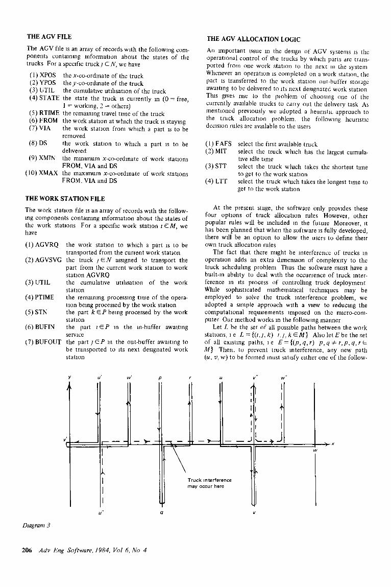
The fact that there might be Interference of trucks in operation adds an extra dimension of complexi ty to the truck scheduling problem Thus the software must have a built-in ablhty to deal with the occurrence of truck inter- ference m its process of controlling truck deployment While sophisncated mathematical techmques may be employed to solve the truck anterference problem, we adopted a simple approach with a view to reducing the computat ional requirements amposed on the micro-com- puter Our method works in the following manner
Let L be the set of all possable paths between the work stations, 1 e L = {(t,l, k) t,l, k ~ M } Also let E be the set of all exastlng paths, ~e E = { ( p , q , r ) p , q - ~ r , p , q , r E M} Then, to prevent truck interference, any new path (u, v, w) to be formed must satisfy either one of the follow.
Diagram 3
V U t W' /3 /" U V" W"
v J
L
, I t f [
It +
y o c c u r h e r
u " 17 V
t4t
3 x
206 Adv Eng Software, 1984, Vol 6, No 4

mg two condmons
(i) m a x {xp, xq, x r} < mm {x u, x v, Xw}
(n) mm {xp, xq, x r} > max {x u, x v, Xw}
where x z is the x-co-ordinate of work station t EM, u, v, w E L andp, q, r E E
An example :s given m Dmgram 3 to show how the above condlt:ons work
It should be noted that these condmons wdl also help prevent all the tracks becoming lodged at a particular work stat:on
THE OUTPUT PROCESS
Gwen the mmal conditions and the necessary data, the software wall simulate the operahon of the specified AGV system When the sunulatlon is complete, the following results wdl be available to the users for evaluation
(1) The production rate of each part type in parts/hour (2) The overall production rate of the system m parts/hour (3) The indwldual work station utdlsatlon (4) The mean work station utllisatlon (5) The mdwldual truck utihsatlon (6) The mean truck utlhsatlon
These performance measures are relevant for the design and evaluation of AGV systems As the software is de- veloped, other transient results such as the queue length and queue tune of mdwidual work station buffers wall also be avadable It is expected that the software wall provide a rapid and cost effective means of detailed assessment of alternative AGV system configurations
IMPLEMENTATION AND FUTURE DEVELOPMENTS
A computer program has been successfully constructed in accordance with the design specifications discussed m the previous section The program is written m PASCAL source code to run on a PRIME-550 computer PASCAL Is chosen because it is a modern and efficient programming language and PASCAL compilers are available on a wide range of mini- and uncro-computers The program has been carefully tested to make sure that it is free from both computational and logacal errors Extensive running of the program under different operating condmons has been carried out and the results are vahdated by detaaled hand calculations It has now been shown that the program is functioning properly A simphfied flow-chart of the program is gwen m the Appendix A copy of the complete hstmg of the program is avadable from the author on request
The program has been apphed to study the effect of different truck allocation rules on the performance of an FMS ~ It has been proved to be useful in determining the optimal number of trucks, the opttmal truck speed and evaluating the system layout The program may also be used to assess different operational strategies regarding part release, part-mix and number of part types to be allowed into the system
As regards future developments, work is now being undertaken to transfer the program to run on an lntel SYS310 computer, which is the designated micro-computer of the project Concurrently, research is being carried out on developing wsual axds in the form of animation of the traffic flow m the system Graphacal presentations o f the
sunulatlon results wall also be avadable m the future It is env:saged that the outcome of this research wall be a piece of mteractwe and real-tune computer software a~d to assist manufacturers m FMS design
REFERENCES
1 Cheng, T C E A Progress Report on the Destgn o f the Material Hanclhng Module, 1984, Department of Engineering Production, Umverslty of Technology, Loughborough, England
APPENDIX
A s tmphf ied f low-chart o f the program
program
t )1 Inspect the f,rst I work statlon
i.
~ Inspect the next ~( ~ w o r k statlon
Choose the next truck (startlng from the flrst) accordlng to the truck allocatlon rule in use
I ~ , ' 1 Update the AGV and work ~ [ station f i les [
/ Has the ~ . t , Slmulatlon tlme ~>q-~Advance the clock 1
, ! output the resu,ts 1
Since
max {xp, xq, Xr} = X r < X u = mln {xu, xv , Xw}
path {u, v, w} IS feasible
Slmdarly
mln {xp, xq, xr} = xp = xq > x w, = max {Xu, , Xv, , Xw, }
path {u', v', w'} is also feasible
However, path {u", v", w"} is feasible since
rain {Xu,, , x v . , x w,, } = Xu" < xp = mln {xp, Xq, xr}
and
max {Xu,, , xv,, , Xw" } = Xw" > Xr = max {xp, xct, xr}
A d v Eng Sof tware , 1984, Vol 6, N o 4 207