Embed Size (px)
Citation preview
A Software Defined Radio Platformwith Raspberry Pi and Simulink
Gianni Pasolini, Flavio ZabiniWilab, University of Bologna
Bologna (Italy)Email: [email protected]
Alessandro BazziIEIIT-CNR
Bologna (Italy)Email: [email protected]
Stefano OlivieriThe MatWorks Inc.
Turin (Italy)Email: [email protected]
Abstract—The Raspberry Pi is a low cost single-board com-puter that gained recently the attention of hobbyists and practi-tioners, especially for file server and media server applications.Thanks to the free support package released by MathWorks, itis fully supported by Simulink, hence it can be programmedaccording to the model-based design paradigm. This means thatalso users with no programming skills can design and implementtheir own applications on Raspberry Pi boards.
In this paper we show how Raspberry Pi’s boards can be used,jointly with Simulink, to easily implement digital communicationsystems. This allows the realization of practical experiences,intended for use within telecommunication courses, that providea viable low-cost way to introduce students to the software-definedradio paradigm.
I. INTRODUCTION
The last decade witnessed an impressive development ofprogrammable microchips specifically designed for signal pro-cessing tasks, such as field programmable gate arrays (FPGAs)and digital signal processors (DSPs). Such devices made thesoftware defined radio (SDR) concept a solid reality, so thatnowadays the baseband section of a communication systemcan be implemented by the software running on such hardware.
Modern telecommunication engineers need, therefore, abroad expertise in the SDR field, encompassing programminglanguages, digital signal processing techniques and hardware-related issues, which should be primarily acquired during theirclasses at the University.
Unfortunately, although telecommunication laboratory fa-cilities are usually available within Electronic and Telecom-munication Faculties, practical SDR experiences are seldomproposed within courses, for two main reasons:
• the cost of the hardware (DSP and FPGA developmentkits), that can hardly be replicated in many workingstations and, above all, left in the hands of inexperiencedusers,
• the complexity of such experiences, which require afirst teaching phase focused on communication-systemsdesign and digital signal processing aspects, followed bya second phase devoted to the basic of DSP and FPGAprogramming, and a third practical phase dedicated to thehardware implementation and the measurements.
In many cases, therefore, the time reserved to practical SDRexperiences (if any) is a very limited fraction of the duration
of digital signal processing courses, that are more focused ontheoretical aspects.
Both the above issues may be overcome, however, by therecent introduction in the mass market of general purposeprogrammable devices with two fundamental characteristics:
• a very limited cost (few dozens of dollars),• the possibility to automatically generate the software
starting from the functional model of the system tobe implemented, according to the model based design(MBD) paradigm.
The Raspberry Pi board [1] is, perhaps, the most relevantexample of such devices: it is a popular low cost single-boardcomputer developed by the Raspberry Pi Foundation with theintention of promoting the teaching of basic computer science.It is largely used as a server in home networks or as a mediacenter and it is also adopted in many academic courses [2].
What is particularly relevant for the educational purposeaddressed here, is that the Raspberry Pi is fully supported byMathWorks Inc. through the Raspberry Pi Support Package1,that establishes a tight connection between the Raspberry Piand Simulink [3]. This “marriage” allows the realization ofa powerful, yet simple, SDR educational platform. Simulinkallows, in fact, the graphical modeling and the simulation ofthe system to be implemented, and then translates the modelinto software, which is downloaded on the device, thanks to theautomatic code generation carried out by the Support Package.
This is making possible the realization of the SDR practicalexperiences that we are collecting in [4], which don’t requireany programming skills and can be implemented at a very lim-ited cost. Students facing the experimental activities, equippedwith the Raspberry Pi as well as one PC hosting Simulink andthe basic instrumentation of a telecommunication laboratory(signal generator, oscilloscope, ...), will be able to experiencethe full life-cycle of a project, from the design and thesimulation to the hardware implementation and the subsequentmeasurements. This is what we call Simulink defined radio.
In the following a description of the SDR educationalplatform is provided, along with an example of experimentalactivity already developed.
1Hardware Support Packages are specific add-ons that enable the use ofMathWorks product with third-party hardware.
2016 24th European Signal Processing Conference (EUSIPCO)
978-0-9928-6265-7/16/$31.00 ©2016 IEEE 398

Fig. 1. Raspberry Pi 2 Model B.
(a)Externalsound card.
(b) Micro SDmemory card.
(c) USB toLAN adapter.
(d) USB-microUSB cable.
(e) LAN ca-ble.
(f) Stereo3.5mm-RCAjack cable.
(g) RCA-BNC adapter.
Fig. 2. Additional hardware.
II. THE RASPBERRY PI
The Raspberry Pi 2 Model B, which is the 2nd generationRaspberry Pi model shown in Fig. 1, is a credit-card sizedsingle-board computer equipped with a quad-core BroadcomBCM2836 ARM v7 processor running at 900MHz. Despite itslow cost, in the order of 40$, it features 1GB RAM, a 40 pinGPIO connector, four USB ports, a 4-pole stereo output andcomposite video port, a HDMI port, a CSI connector, a DSIconnector, a micro-SD card slot and an Ethernet socket.
It gained the attention of hobbyists and practitioners espe-cially for file server and media server applications. Nowadays,there are plenty of existing projects, easily available on theInternet, which work on 1st generation or 2nd generation Rasp-berry Pis. Expert users can also develop their own applicationsusing Python or other programming languages, taking benefitfrom the availability of such a versatile and cheap device torealize customized solutions to their needs.
In this paper we show an unconventional usage of Rasp-berry Pi boards: deprived of input/output peripherals suchas monitor, keyboard, and mouse, and added of the cablesand connectors summarized in Fig. 2 (and better discussed inSection IV-A), they can be used as DSPs for the realizationof communication systems and signal processing subsystems.
To achieve this goal, both an analog input and an analogoutput are required. Since the Raspberry Pi does not have
Fig. 3. Comparison between the external DAC output and the Raspberry Pi 2Model B headphones output. 10 kHz sine wave.
natively an analogue output, we used an external USB soundcard with the 33051D chipset, like the one shown in Fig. 2(a),that supplies a microphone input and one more headphonesoutput.
This cheap device (about 20$), connected to the Rasp-berry Pi’s USB port, actually plays a double role: analog todigital converter (ADC) for the input signals and digital toanalog converter (DAC) for the output signals. As the device isconceived for audio signals, its sampling frequency is limitedto 48000 samples per second, with a resolution of 16 bitsper sample. It follows that the band of generated and receivedsignals must be within the interval [0, 24 kHz]. This should notbe deemed a problem, however, because the signal bandwidthis not really relevant for teaching purposes. In the case ofdigital transmissions, for instance, the transmitter architecturedoes not change at all, and it simply entails that the bit ratemust be kept low.
Observe, finally, that although the Raspberry Pi is equippedwith an integrated audio output (headphones output), it issurely preferable to use the analog output provided by theexternal sound card. The integrated DAC is, in fact, a low costcomponent and the poor quality of its output can be observedfor example in Fig.3, where the yellow curve represents a 10kHz sine generated by a Raspberry Pi and measured at theintegrated output, whereas the red curve represents the samesignal measured at the sound card output. As clearly evident,the signal generated by the built-in DAC is quite distorted.
III. SIMULINK AND THE MODEL BASED DESIGNPARADIGM
Simulink, developed by MathWorks, is a graphical exten-sion to MATLAB for modeling and simulation of linear andnonlinear dynamic systems.
In Simulink, systems are drawn on screen by means ofsimple drag-and-drop operations of elementary blocks, that areinterconnected each other to realize the final block diagram.The elementary blocks are collected in a comprehensive libraryof toolboxes, that includes also virtual input and output devicessuch as function generators and oscilloscopes.
2016 24th European Signal Processing Conference (EUSIPCO)
399
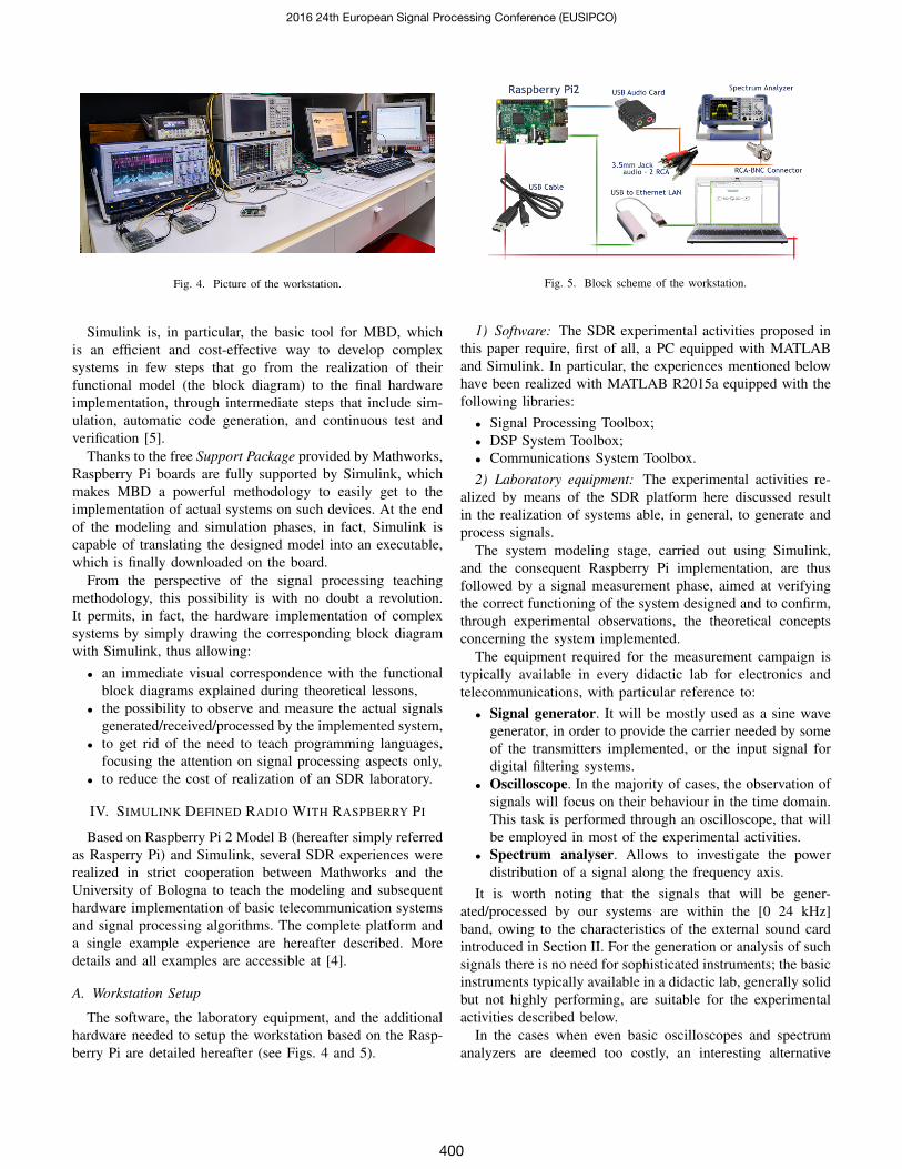
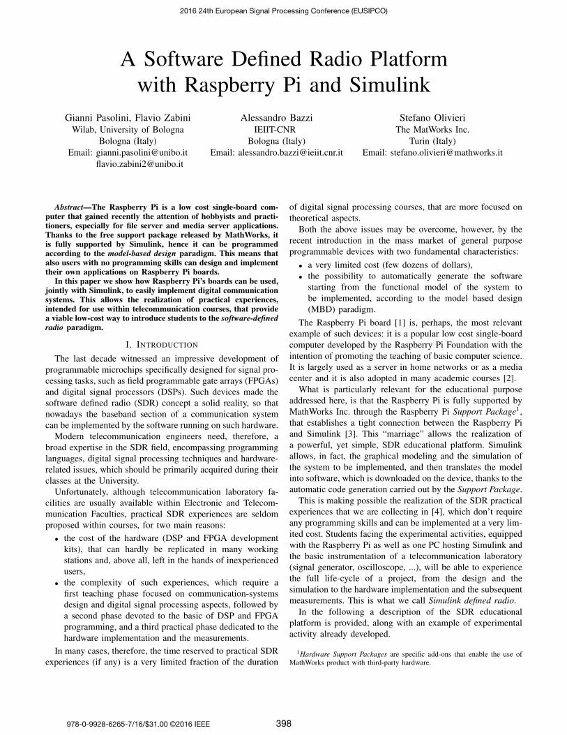
Fig. 4. Picture of the workstation.
Simulink is, in particular, the basic tool for MBD, whichis an efficient and cost-effective way to develop complexsystems in few steps that go from the realization of theirfunctional model (the block diagram) to the final hardwareimplementation, through intermediate steps that include sim-ulation, automatic code generation, and continuous test andverification [5].
Thanks to the free Support Package provided by Mathworks,Raspberry Pi boards are fully supported by Simulink, whichmakes MBD a powerful methodology to easily get to theimplementation of actual systems on such devices. At the endof the modeling and simulation phases, in fact, Simulink iscapable of translating the designed model into an executable,which is finally downloaded on the board.
From the perspective of the signal processing teachingmethodology, this possibility is with no doubt a revolution.It permits, in fact, the hardware implementation of complexsystems by simply drawing the corresponding block diagramwith Simulink, thus allowing:
• an immediate visual correspondence with the functionalblock diagrams explained during theoretical lessons,
• the possibility to observe and measure the actual signalsgenerated/received/processed by the implemented system,
• to get rid of the need to teach programming languages,focusing the attention on signal processing aspects only,
• to reduce the cost of realization of an SDR laboratory.
IV. SIMULINK DEFINED RADIO WITH RASPBERRY PI
Based on Raspberry Pi 2 Model B (hereafter simply referredas Rasperry Pi) and Simulink, several SDR experiences wererealized in strict cooperation between Mathworks and theUniversity of Bologna to teach the modeling and subsequenthardware implementation of basic telecommunication systemsand signal processing algorithms. The complete platform anda single example experience are hereafter described. Moredetails and all examples are accessible at [4].
A. Workstation Setup
The software, the laboratory equipment, and the additionalhardware needed to setup the workstation based on the Rasp-berry Pi are detailed hereafter (see Figs. 4 and 5).
Fig. 5. Block scheme of the workstation.
1) Software: The SDR experimental activities proposed inthis paper require, first of all, a PC equipped with MATLABand Simulink. In particular, the experiences mentioned belowhave been realized with MATLAB R2015a equipped with thefollowing libraries:
• Signal Processing Toolbox;• DSP System Toolbox;• Communications System Toolbox.2) Laboratory equipment: The experimental activities re-
alized by means of the SDR platform here discussed resultin the realization of systems able, in general, to generate andprocess signals.
The system modeling stage, carried out using Simulink,and the consequent Raspberry Pi implementation, are thusfollowed by a signal measurement phase, aimed at verifyingthe correct functioning of the system designed and to confirm,through experimental observations, the theoretical conceptsconcerning the system implemented.
The equipment required for the measurement campaign istypically available in every didactic lab for electronics andtelecommunications, with particular reference to:
• Signal generator. It will be mostly used as a sine wavegenerator, in order to provide the carrier needed by someof the transmitters implemented, or the input signal fordigital filtering systems.
• Oscilloscope. In the majority of cases, the observation ofsignals will focus on their behaviour in the time domain.This task is performed through an oscilloscope, that willbe employed in most of the experimental activities.
• Spectrum analyser. Allows to investigate the powerdistribution of a signal along the frequency axis.
It is worth noting that the signals that will be gener-ated/processed by our systems are within the [0 24 kHz]band, owing to the characteristics of the external sound cardintroduced in Section II. For the generation or analysis of suchsignals there is no need for sophisticated instruments; the basicinstruments typically available in a didactic lab, generally solidbut not highly performing, are suitable for the experimentalactivities described below.
In the cases when even basic oscilloscopes and spectrumanalyzers are deemed too costly, an interesting alternative
2016 24th European Signal Processing Conference (EUSIPCO)
400
Fig. 6. Simulink model of the OFDM transmitter.
is the use of the Digilent Analog Discovery device, whichis a low cost multi-purpose instrument conceived for lowfrequency applications. When connected to the PC throughthe USB port, this device is able to generate and acquiresignals. With a moderate price, in the order of 270$, thistool can operate as signal generator, oscilloscope, spectrumanalyzer, network analyzer, logic state analyzer, digital signalgenerator, and power supply. The user interface of each singleinstrument, displayed on the PC’s monitor, shows the sameknobs, sliders and buttons of the full hardware instrument,allowing the user to perform the measurement activity asif he were in a lab. Of course, the bandwidth that can behandled by the Digilent Analog Discovery, in the order of someMHz, cannot be compared with that of more sophisticated andexpensive instruments, however it is more than adequate forthe didactic experiences carried out with our SDR platform.In this case, therefore, the signal generator, the oscilloscopeand the spectrum analyzer can be conveniently replaced bythis multifunction tool.
3) Additional hardware: In addition to the Raspberry Pi,the PC hosting Simulink, and the laboratory equipments, thehardware depicted in Fig. 2 is needed:
• Nr. 1 External sound card (Fig. 2(a)). As explained inSection II, it is used to provide the Raspberry Pi with ananalog input, otherwise absent, and with a higher qualityanalog output.
• Nr. 1 Micro SD memory card (Fig. 2(b)). It containsthe Raspberry Pi operating system.
• Nr. 1 USB to LAN adapter (Fig.2(c)). If the PC’sEthernet port is not available, this adapter allows toconnect the Raspberry Pi to the PC using the USB port.
• Nr. 1 USB-micro USB cable (Fig. 2(d)). It is used toconnect the Raspberry Pi to the PC’s USB port, with theonly aim to provide the power supply.
• Nr. 1 Network cable (Fig. 2(e)). It is used to connectthe Raspberry Pi to the PC.
• Nr. 2 3.5 mm-RCA jack cables (Fig. 2(f)). They areused to connect the sound card, equipped with 3.5 mmfemale jacks (Fig. 2(a)), to the instruments. RCA-BNCadapter (Fig. 2(g)) are also needed.
• Nr. 2 RCA-BNC adapter (Fig. 2(g)). They are used toconnect the 3.5 mm-RCA jack cable to the instruments,
usually equipped with BNC connectors (Fig.2(f)).The cost of all the additional hardware remains below 60$.
The basic workbench setup is shown in Fig. 5: one PChosting Simulink connected, through an Ethernet link, to theRaspberry Pi, whose output is fed to an oscilloscope and/ora spectrum analyzer. Some experiences also require a signalgenerator, whose task is to provide the Raspberry Pi with anexternal signal (such as the carrier).
B. Developed experiences
As already stated, several SDR experiences are being devel-oped in the framework of a cooperation between Mathworksand the University of Bologna, using the above described plat-form. In particular, the following systems have been alreadyimplemented:
• Signal generator;• 2-PAM and 4-PAM baseband transmitters;• 2-ASK and 4-ASK transmitters;• FSK transmitter;• Q-PSK transmitter;• OFDM transmitter (64 and 256 carriers);• Digital filtering;• Adaptive noise canceler.
The corresponding Simulink models and the related documen-tation, conceived as material to be provided to students, canbe freely downloaded at [4]. For the sake of conciseness, onlythe example case of an OFDM transmitter is here presented.
V. EXAMPLE: RASPBERRY PI AS AN OFDM TRANSMITTER
To provide an example case, the Simulink model that hasbeen developed to implement an OFDM transmitter is shownin Fig. 6.2 To simplify the description, the following sevenmacro-blocks have been highlighted in the figure:
1) Symbol generation: The Symbol generation macro-block generates real symbols ai ∈ {−1, 1}, starting fromthe bits produced by the Bernoulli Binary Generator block.Such symbols will be used to modulate the subcarriers of theOFDM signal; as the alphabet used has just two symbols, themodulation adopted for the subcarriers is 2-ASK. The bit rateis set to 1800 bits/s.
2In order to keep the model as simple as possible we did not implementthe cyclic-prefix.
2016 24th European Signal Processing Conference (EUSIPCO)
401
2) OFDM modulator: Starting from the symbols ai atits input, the OFDM modulator macro-block generates thebaseband signal corresponding to an OFDM modulation withN = 64 subcarriers, Nu = 48 of which are actually used totransmit modulation symbols (useful subcarriers) whereas theremaining Nz = 16 have null amplitude (15 virtual subcarriers+ 1 DC subcarrier in correspondence of the frequency zero3).More specifically, the N = 64 subcarriers are used as follows:
• 8 virtual subcarriers (from 1 to 8) with null amplitude;• 24 data subcarriers (from 9 to 32) with 2-ASK modula-
tion;• 1 DC subcarrier (number 33) with null amplitude (corre-
sponding to the zero frequency);• 24 data subcarriers (from 34 to 57) with 2-ASK modu-
lation;• 7 virtual subcarriers (from 58 to 64) with null amplitude.
With the introduction of the virtual and DC subcarriers, theoutput sampling rate of the OFDM macro-block is 2400 sam-ples/s. Data are organized in frames to simplify the real timemanagement by the hardware.
3) Upsampling: In order to modulate the baseband OFDMsignal, the sampling frequency must be increased. It is conve-nient, on this regard, to increase it by a factor of 20, taking itto the 48000 samples/s required by the audio card’s DAC. Theupsampling operation is performed by the sequence of blocksincluded in the Upsampling macro-block, that performs anupsampling by a factor of 2 at first and then by a factor of10. The two stage procedure is preferable, compared with asingle stage upsampling by a factor of 20, because it reducesthe overall computational burden [6], [7].
4) Baseband to IF: The Baseband to IF macro-block mod-ulates the signal, translating it from baseband to intermediatefrequency. Such operation is performed through a quadraturemodulator with internally generated carriers at a frequencyfIF = 15 kHz. The Baseband to IF macroblock is a classicquadrature modulator, with two separate paths for the real(in-phase) and the imaginary (quadrature) components of thesignal. Each component is upconverted by a mixer (representedby the Product block) driven by a cosine or a sine carrier,generated by the Cosine Wave and Sine Wave blocks. Bothmodulated signals are then summed up and taken out.
5) Automatic Gain Control: The Automatic Gain Controlmacro-block adapts the signal’s dynamic range to the require-ments of the output port. As a consequence of this operation,the highest value in each frame is equal to 214− 1, consistentwith the highest value required by the output port (215 − 1).
6) Raspberry Pi output: The Raspberry Pi output macro-block represents the system output port. It corresponds, there-fore, to the sound card’s DAC.
Once the Simulink model is realized and checked throughSimulink simulations, it is possible to carry out the Deployto Hardware, which is triggered by Simulink itself. The
3In order to facilitate the receiver in the research of the band center, thesubcarrier corresponding to the zero frequency (in the baseband) is usuallyassigned a null amplitude. The acronym DC means Direct Current.
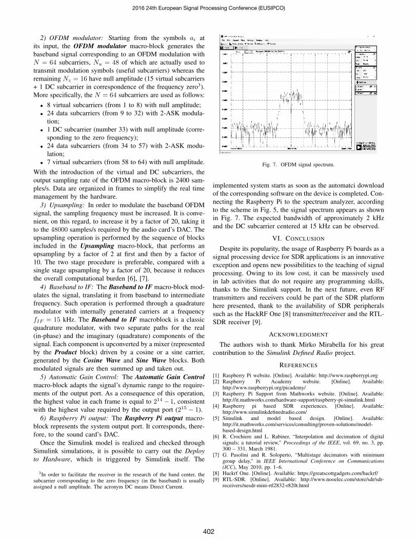
Fig. 7. OFDM signal spectrum.
implemented system starts as soon as the automatci downloadof the corresponding software on the device is completed. Con-necting the Raspberry Pi to the spectrum analyzer, accordingto the scheme in Fig. 5, the signal spectrum appears as shownin Fig. 7. The expected bandwidth of approximately 2 kHzand the DC subcarrier centered at 15 kHz can be observed.
VI. CONCLUSION
Despite its popularity, the usage of Raspberry Pi boards as asignal processing device for SDR applications is an innovativeexception and opens new possibilities to the teaching of signalprocessing. Owing to its low cost, it can be massively usedin lab activities that do not require any programming skills,thanks to the Simulink support. In the next future, even RFtransmitters and receivers could be part of the SDR platformhere presented, thank to the availability of SDR peripheralssuch as the HackRF One [8] transmitter/receiver and the RTL-SDR receiver [9].
ACKNOWLEDGMENT
The authors wish to thank Mirko Mirabella for his greatcontribution to the Simulink Defined Radio project.
REFERENCES
[1] Raspberry Pi website. [Online]. Available: http://www.raspberrypi.org[2] Raspberry Pi Academy website. [Online]. Available:
http://www.raspberrypi.org/picademy/[3] Raspberry Pi Support from Mathworks website. [Online]. Available:
http://it.mathworks.com/hardware-support/raspberry-pi-simulink.html[4] Raspberry pi based SDR experiences. [Online]. Available:
http://www.simulinkdefinedradio.com/[5] Simulink and model based design. [Online]. Available:
http://it.mathworks.com/services/consulting/proven-solutions/model-based-design.html
[6] R. Crochiere and L. Rabiner, “Interpolation and decimation of digitalsignals; a tutorial review,” Proceedings of the IEEE, vol. 69, no. 3, pp.300 – 331, March 1981.
[7] G. Pasolini and R. Soloperto, “Multistage decimators with minimumgroup delay,” in IEEE International Conference on Communications(ICC), May 2010, pp. 1–6.
[8] Hackrf One. [Online]. Available: https://greatscottgadgets.com/hackrf/[9] RTL-SDR. [Online]. Available: http://www.nooelec.com/store/sdr/sdr-
receivers/nesdr-mini-rtl2832-r820t.html
2016 24th European Signal Processing Conference (EUSIPCO)
402