Embed Size (px)
Citation preview
1
A Space-Time Analysis of LTE and Wi-FiInter-working
Youjia Chen, Ming Ding, Member, IEEE, David Lopez-Perez, Member, IEEE,Zihuai Lin, Senior Member, IEEE, and Guoqiang Mao, Senior Member, IEEE
Abstract—Cooperative inter-working of the Long Term Evo-lution (LTE) and the Wireless Fidelity (Wi-Fi) networks havedrawn much attention recently, and several strategies have beenproposed to enhance their network capacity. In this paper, wepropose a new framework to analyse the network performanceof several inter-working strategies for the LTE and the Wi-Fi.The proposed framework considers both the LTE and the Wi-Fisystems, both the downlink (DL) and the uplink (UL) trans-missions, and the generated interference in both the time andthe spatial domains. Based on such framework, we theoreticallyanalyse for the first time the performance of a Wi-Fi network,taking into account the intra-cell time efficiency, and the signaland inter-cell interference with spatial randomness. Moreover, westudy the performance of i) a coexisting architecture where Wi-Ficoexists with an ideal CSMA duplex (ID-CSMA) system, whichrepresents an upper bound performance for the LTE Release14 licensed assisted access (LAA) network, and ii) a brand-newarchitecture that allows UL on LTE and DL on Wi-Fi, referredto as the Boost architecture. We derive analytical results for boththe DL and the UL network performance in terms of the signalquality distribution and the total area system throughput (AST)in these two architectures, and quantify their performance gaincompared with the traditional disjoint LTE Wi-Fi architecture.Simulation results validate our analysis results, and show thatin a typical outdoor scenario, the coexisting architecture and theBoost architecture can respectively increase the total AST up to11% and 25%, compared with the traditional disjoint LTE Wi-Fi.
I. INTRODUCTION
The use of unlicensed spectrum by mobile network op-erators, particularly in the 5 GHz band, has recently beenattracting considerable attention, and vendors and operators arealready actively studying its viability for long term evolution(LTE)/4G cellular networks [1]. The use of the unlicensedspectrum for cellular operation represents a significant changein cellular network deployment and management, and there
Youjia Chen is with the School of Electrical and Information Engineering,The University of Sydney, Australia, with Fujian Normal University, China,and also with Data61, CSIRO, Australia. E-mail: [email protected].
Ming Ding is with Data61, CSIRO, Australia. E-mail:[email protected].
David Lopez-Perez is with Bell Laboratories, Nokia, Ireland. E-mail:[email protected].
Zihuai Lin is with the School of Electrical and Information Engineering,The University of Sydney, Australia, and also with Data61, CSIRO, Australia.E-mail: [email protected].
Guoqiang Mao is with the School of Computing and Communications, TheUniversity of Technology Sydney, Australia, and also with Data61, CSIRO,Australia. E-mail: [email protected].
This work is supported by the Fujian Provincial Natural Science Foundation(No. 2016J01290), the National Natural Science Foundation of China (No.61571128) and the China Scholarship Council.
are, at this stage, still many open questions in terms of bothbusiness case and technology as a whole.
A major aspect of ongoing discussions is the requirementto provide fair co-existence between this new unlicensed LTEtechnology and other technologies working in the unlicensedspectrum. Given that current technologies in unlicensed bands,such as Wireless Fidelity (Wi-Fi) [2], rely on contention-basedaccess, there is a concern that starvation and other forms ofunfairness may occur when they co-exist with a schedule-based technology such as LTE [3, 4]. Co-existence of multipleLTE operators within the same unlicensed band is also a majorconcern.
A. The Related 3GPP Standardisation
Two major approaches are being considered within the ThirdGeneration Partnership Project (3GPP) to address this issue,where the main difference between them both is that oneuses LTE radio access technology to operate the unlicensedspectrum, while the other accesses it through IEEE 802.11standards.
The first approach aims at using LTE infrastructure toaccess the unlicensed band, and thus calls for a harmoniouscoexistence of this new LTE deployments with the existingWi-Fi networks in the unlicensed spectrum. The Licensed-assisted access (LAA) [5] technology can be classified withinthis category, where listen-before-talk (LBT) is the techniqueused to reinforce co-existence and conform with, for instance,European and Japanese regulations. It is important to note thatthe LBT used by LAA is similar to the carrier sense multipleaccess/collision avoidance (CSMA/CA)1 medium access con-trol (MAC) used by Wi-Fi. A significant advantage of usinga similar random access procedure to Wi-Fi devices to wintransmission opportunities is that fair co-existence with themcan be more easily guaranteed. Importantly, co-existence ofmultiple LTE networks within the unlicensed band can alsobe ensured in a more straightforward manner.
The second approach aims at leveraging Wi-Fi infrastructureto access the unlicensed spectrum. Thus, it does not attempt todeploy LTE infrastructure in the unlicensed band but insteadseeks to enhance Wi-Fi performance through inter-workingtechniques.LTE-WLAN Aggregation (LWA) and LTE WLANRadio Level Integration with IPsec Tunnel (LWIP) [6–8] areexamples of this category, where a tight integration of LTEand Wi-Fi allows enhanced performance and quality of service
1An overview of CSMA/CA is provided in Appendix A
2
provisioning. In contrast to LAA, since LWA and LWIP tech-nologies access the unlicensed technology through certifiedWi-Fi technology, co-existence and regulatory requirementsare not a concern for them.
B. Related Work
In order to obtain a deeper understanding of different men-tioned LTE and Wi-Fi cooperation strategies, a new frameworkis needed to theoretically analyse the network performanceconsidering the features of both LTE and Wi-Fi.
Stochastic geometry has recently become a popular andpowerful mathematical tool to analyse large-scale wirelessnetworks. In more detail, by modelling the locations of basestations (BSs) and/or access points (APs) and/or UEs as spa-tially random point process, several key network performancemetrics can be derived.
The performance of LTE has been well analysed using thestochastic geometry theory. In [9–11], the coverage probabilityand average network capacity were derived for the DL andUL of cellular networks with BSs following the homogeneousPoisson Point Process (HPPP).
In contrast, the performance analysis for Wi-Fi mainlyconsists of two aspects:
• The Time-Domain Analysis: Regarding the time-domainanalysis of Wi-Fi, in [12], the authors proposed a two-dimensional (2-D) Markov chain model to analyse thesystem utility of a stand-alone Wi-Fi system under theassumption of ideal channel conditions and a finite num-ber of saturated terminals. Such 2-D model was extendedin various ways to consider non-saturated traffic, infinitebuffer and buffer-less cases, different QoS parameters,etc. [13–15]. However, all of these works were limited toa stand-alone, single cell Wi-Fi system. In practice, theinteraction among adjacent Wi-Fi systems in the spatial-domain should be considered, especially for dense Wi-Finetworks.
• The Spatial-Domain Analysis: Regarding the spatial-domain analysis of Wi-Fi, in [16], the authors proposedthe use of a modified Matern hard-core point process(MHCP) to analyse a dense Wi-Fi network, which in-vestigates a snapshot of nodes that can transmit simulta-neously according to the CSMA/CA protocol. However,it did not capture the time-domain features of Wi-Fi suchas colliding transmissions, exponential back-off and soon, which have a large impact in Wi-Fi systems. Thesame issue exists in recent works, which analyze theperformance of LAA networks [4, 17]. Moreover, all ofthese existing works focused on the DL transmissionsonly, and did not treat the UL transmissions, which arethe main source of Wi-Fi performance degradation dueto intra-cell channel contentions [17].
C. Contributions
The contributions of this paper are four-fold:• We introduce a new network performance analysis for
Wi-Fi networks that simultaneously considers the DL and
UL transmissions and jointly investigates 1) the intra-celltime efficiency degradation caused by the random back-off scheme and transmission collisions, 2) the signal andinter-cell interference with the spatial randomness of APsand UEs, and more importantly 3) the interaction betweenthe time domain and the spatial domain.
• Based on the above framework, we present a new het-erogeneous MHCP model to analyse the inter-cell inter-ference when LTE and Wi-Fi share the same bandwidth.Using this model, we derive the performance of a co-existing architecture where Wi-Fi coexists with an idealCSMA duplex (ID-CSMA) systems, which achieves anupper bound performance for the LTE Release 14 LAAsystems.
• Moreover, we derive the theoretical results on the per-formance of Boost, the predecessor of LWIP, which usesDL on Wi-Fi and UL on LTE.
• By analysing the network performance of traditionaldisjoint LTE and Wi-Fi architecture, the coexisting ar-chitecture and Boost, we can quantify the performancegain of these various strategies in terms of area systemthroughput (AST), which sheds valuable insights on theinter-working of LTE and Wi-Fi systems.
D. Paper Structure
The rest of the paper is organised as follows: In Section II,the system model and three different network architecturesare described. In Section III, the existing results for LTEsystem performance analysis are presented, while the networkperformance of traditional Wi-Fi networks is studied in Sec-tion IV. Then the performance of coexisting Wi-Fi and ID-CSMA systems and the proposed Boost technology are studiedin Section V and VI, respectively. In Section VII and VIII, theanalysis results and conclusions are discussed, respectively.
II. INTER-WORKING STRATEGIES AND SYSTEM MODEL
In this section, we present the inter-working strategies andsystem model used in this paper.
A. The Analysed Inter-Working Strategies
Inline with the introduction, two unlicensed technologiesare analysed in this paper, namely ID-CSMA and Boost.
1) ID-CSMA Systems in Unlicensed Spectrum: In contrastto the standardised LAA technology in LTE Release 13,which only supports LTE DL transmission in the unlicensedbands, we consider a system that supports both DL andUL transmissions and falls within the scope of LAA tech-nology in LTE Release 14. Since the details of the ULtransmission for LAA cells in LTE Release 14 are still underinvestigation/development, we model instead the performanceof an idealised LAA-like system, referred to as ID-CSMAsystem, which gives an upper bound performance of the LAAtechnology in LTE Release 14, and can be used as a referencefor system design.
The UL transmissions in this ID-CSMA system are assumedto be well-scheduled under the assistance of the licensed band,
3
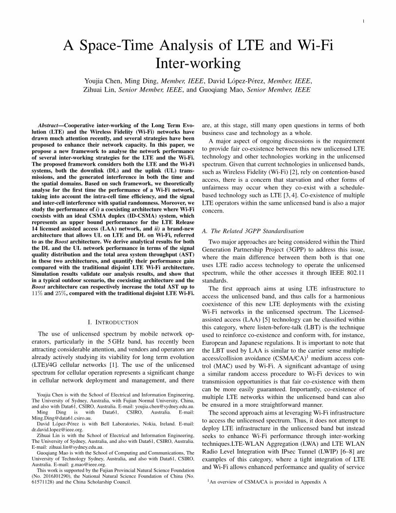
as the DL transmissions in LAA Release 13. Fig. 1 showsan example of data transmission in the considered ID-CSMAsystem, where the cell uses the CCA to ensure the channel isidle before transmission and the random back-off scheme toavoid collisions among cells. When the ID-CSMA cell gainsaccess to the channel, it transmits control signalling containingscheduling information for the DL or the UL (i.e., PDCCHor PUCCH), followed by the actual UE data (i.e., PDSCHor PUSCH) within the maximum channel occupancy time.The assumption is that no LBT is used at the UE, which asmentioned earlier should reflect the upper bound performance.
!"##$%&'()*
'"+,-..
/0120&'(3)4
5"678(8& !"##$%&9++(:"#+*&;78$
</ =1<2 =
</> =1<2> =
?8)
Fig. 1. An illustration of an ID-CSMA data transmission.
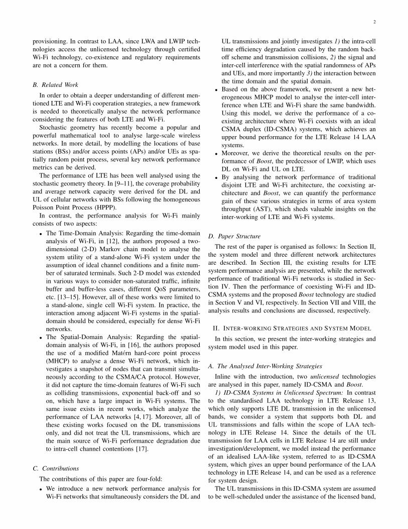
2) Boost: Boost is a brand-new technology that uses DL onWi-Fi and UL on LTE [18]. As shown in Fig. 2, by redirectingUL traffic from the Wi-Fi network in the unlicensed band tothe LTE network in the licensed band, Wi-Fi operates only inthe DL and works on a centralised scheduled basis (DL Wi-Fitraffic is currently scheduled by the Wi-Fi AP). This allowsan efficient use of Wi-Fi’s large bandwidth, without the delayintroduced by UL contention and in a completely collision-freemanner inside a cell. In this way, Boost allows operators tocombine stand-alone Wi-Fi and LTE networks into one unifiedwireless network for home, office and outdoor environments,and only requires software updates at the network and theUE [19].
B. Network ModelLet us consider a network comprised of licensed and un-
licensed spectrum. The licensed bandwidth used by the LTEsystem is denoted by BL, while the unlicensed bandwidthused by the Wi-Fi/ID-CSMA system is denoted by BW . Thefrequency reuse factor of the LTE systems is 1, while theavailable bandwidth of the Wi-Fi/ID-CSMA system is dividedinto M non-overlapping channels according to the 802.11specifications. In other words, each LTE cell can use the entirelicensed bandwidth, while the bandwidth that each Wi-Fi orID-CSMA cell can use is BW /M .
The distributions of LTE BSs, ID-CSMA BSs and Wi-FiAPs are modelled as independent HPPPs with intensity λL
s ,λAs and λW
s , respectively.The transmission powers of LTE BSs, ID-CSMA BSs and
Wi-Fi APs are denoted by PLs , PA
s and PWs , respectively.
while the transmission powers of LTE UEs, ID-CSMA UEsand Wi-Fi UEs are denoted by PL
u , PAu or PW
u , respectively.
C. Network ArchitecturesIn this paper, we consider three network architectures
corresponding to the different LTE and Wi-Fi inter-workingstrategies as follows.
1) The Traditional Architecture: In this architecture, theLTE and the Wi-Fi systems work independently. The distri-butions of UEs that connect with LTE BSs and Wi-Fi APs aremodelled as independent HPPPs with intensities λL
u and λWu ,
respectively. It is important to note that an FDD LTE system isconsidered where the licensed bandwidth of LTE is split intotwo parts, i.e., the bandwidth for UL transmissions is ςBL,while the bandwidth for DL transmissions is (1− ς)BL.
2) The Coexisting Architecture: In this architecture, LTEBSs work in the licensed spectrum, while ID-CSMA BSs andWi-Fi APs coexist in the unlicensed spectrum. The UEs inthe unlicensed band with density λW
u can be served by ID-CSMA BSs or Wi-Fi APs. Following the co-existence spiritin the 3GPP specifications, an LAA cell should not impactWi-Fi services more than an additional Wi-Fi cell on the samecarrier, and thus we assume that PA
s = PWs and PA
u = PWu .
3) The Boost Architecture: With Boost, all the UL trafficis served by LTE, while all the DL traffic is served by Wi-Fi. As a result, the whole LTE bandwidth BL is used for theLTE UL, the density of UEs served by either LTE or Wi-Fiis λu = λL
u + λWu , and the intra-cell collision is completely
avoided in Wi-Fi due to the centralised DL scheduling at theWi-Fi APs.
D. Channel Model
We assume that each BS/AP/UE is equipped with anisotropic antenna, and that the multi-path fading betweenan BS/AP and a UE is modelled as independently identicaldistributed (i.i.d.) Rayleigh fading.
The power received from a transmitter located at x atlocation y, denoted by P (x, y), is
P (x, y) = Pt · h(x, y) · l(x, y), (1)
where 1) Pt is the transmission power, 2) h(x, y) is the multi-path fading from x to y, which is assumed to be exponentiallydistributed with a mean of one due to our consideration ofRayleigh fading, and 3) l(x, y) = L0∥x − y∥−α is the pathloss between x and y, where L0 is the reference path lossat the unit distance, α is the path loss exponent, and ∥ · ∥ isthe Euclidean norm. In more detail, the reference path lossvalues for the licensed and unlicensed spectrum are denotedby LL
0 and LW0 , respectively, and the path loss exponents for
the licensed and unlicensed spectrum are denoted by αL andαW , respectively.
It is important to note that in the traditional and coexistingarchitectures, since Wi-Fi works in a TDD mode, we have thath(x, y) = h(y, x) due to the channel reciprocity for the DLand the UL.
E. UE Association
As a common practice in the field [17, 20], the nearestassociation scheme is adopted in this work. In more detail, inthe traditional and coexisting architecture, UEs in the licensedband associate with their nearest LTE BS, while UEs in theunlicensed band associate with the nearest Wi-Fi AP or ID-CSMA BS since they have the same transmission power.
4
App server
Network
WiFi APLTE eNB
UEs
UL
DLPoor perf;
too much
contention
Poor DL LTE perf;
due to small BW
UL
DL
Ne
(a) Traditional architecture
App server
Network
WiFi APLTE eNB
UEs
ULUL
DLDL
UL contention
issues solved
Load balanced DL
more BW in WiFi
Ne
(b) Boost architecture
Fig. 2. Boost alleviates WiFi network congestion by diverting UL traffic to the LTE network. Moreover, it alleviates LTE DL congestion by moving DLtraffic to the WiFi network with large bandwidth.
Therefore, the network plane is tessellated into two layer first-order Voronoi cells, i.e., the licensed and the unlicensed layer,where the first-order Voronoi cell V(xi) associated with theBS/AP located at xi, is defined as
V(xi) ,{y ∈ R2 | ∥y − xi∥ ≤ ∥y − xj∥, ∀i = j
}. (2)
III. PERFORMANCE ANALYSIS OF LTE IN THETRADITIONAL ARCHITECTURE
In the traditional architecture, the network can be viewedas a stand-alone LTE system and a stand-alone Wi-Fi systemoperating on different frequency spectrum. Since the perfor-mance of LTE systems have been well studied in the literature,in the following, we directly show the existing results in termsof the average ergodic rate and then formulate the AST. Notethat these existing results are derived based on the assumptionthat the density of UEs is sufficiently larger than that of BSs,which ensures that each BS has at least one UE to serve in itscoverage area2.
A. Average Ergodic RateIn the following, we present the average ergodic rate for the
DL and the UL.1) Average Ergodic Rate in the DL: Denoted by γL
d the DLsignal-to-interference-plus-noise ratio (SINR) in LTE, accord-ing to Theorem 3 in [9], the average ergodic rate of a typicalUE in the DL, denoted by ρLd , can be expressed by
ρLd , E[ln(1 + γL
d )]=
∫ ∞
0
2πλLs r exp
(−πλL
s r2) ∫
t>0
exp
(−σ2rα
L
PLs LL
0
(et − 1)
)· LId
(rα
L
PLs LL
0
(et − 1)
)dtdr, (3)
where
LId
(rα
L
PLs LL
0
(et − 1)
)= exp
(− πλL
s r2(et − 1)
2/αL
∫ ∞
(et−1)−2/αL
1
1 + xαL/2dx). (4)
2In order to satisfy this constraint, we assume λLu > 4λL
s according to thedistribution of the area of Voronoi cells in Eq. (9).
2) Average Ergodic Rate in the UL: Denoted by γLu the UL
SINR in LTE, according to [11], the average ergodic rate ofa typical UE in the UL, denoted by ρLu , can be written as
ρLu , E[ln(1 + γL
u )]=
∫ ∞
0
2πλLs r exp
(−πλL
s r2) ∫
t>0
exp
(− σ2(et − 1)
PLu ( 1
LL0rαL)
(ϵ−1)
)LIu
(et − 1
PLu ( 1
LL0rαL)
(ϵ−1)
)dtdr,
(5)
where ϵ ∈ [0, 1] is the UL power control factor and
LIu (s) = exp
(−2πλL
s
∫ ∞
r
∫ x
0
2πλLs u exp(−λL
s πu2)(
1− 1
1 + sPLu ( 1
LL0uαL)
ϵLL0 x
−αL
)duxdx
). (6)
B. Area System Throughput
Based on the average ergodic rates in the DL and the ULin (3) and (5), and considering the bandwidth allocated to theDL and UL, the system throughput per unit area, i.e., the areasystem throughput (AST), of the LTE system in the licensedband can be formulated as
ASTL = λLs B
L(ςηLu ρ
Lu + (1− ς) ηLd ρ
Ld
), (7)
where ηLu and ηLd are the effective resource utilization factors(less than one due to control signalling overhead) of thephysical and MAC layers in the respective LTE UL and DL.
IV. PERFORMANCE ANALYSIS OF WI-FI IN THETRADITIONAL ARCHITECTURE
The network performance of Wi-Fi, in terms of the averageergodic rate and the AST, jointly considering the DL and theUL as well as the time and the spatial domains, have not beeninvestigated yet in the literature. For the first time, we tacklethis problem and present our main results in the following.
5
A. Intra-Cell Analysis for Wi-Fi
We consider a typical UE located at the origin o, whoseserving AP is located at x0 with polar coordinates (r, 0), wherer = ∥x0∥. According to the Voronoi cell definition in (2), thecell managed by the AP located at x0 is denoted by V(x0).Due to the nearest association scheme, the probability densityfunction (PDF) of r is given by
f(r) = 2πλWs r exp(−λW
s πr2). (8)
1) The Number of UEs Associated with an AP: We denotethe area size of an AP’s first-order Voronoi cell by s. Accord-ing to [21], the PDF of s can be approximated as
f(s) =(λW
s K)K
Γ(K)s(K−1) exp
(−KλW
s s), (9)
where Γ(K) =∫∞0
xK−1 exp(−x)dx is the Gamma function,and K ≈ 3.575.
Since the distribution of UEs follows an HPPP with anintensity of λW
u , given a Voronoi cell with area size s, thenumber of UEs located in this Voronoi cell should follow aPoisson random variable with mean λW
u s. Denoting by n thenumber of UEs located in a Voronoi cell, we have that
Pr(n = N) =
∫ ∞
0
(λWu s)N
N !exp(−λW
u s)f(s)ds
=Γ(N +K)
N ! · Γ(K)
(λWu
λWu +KλW
s
)N (1− λW
u
λWu +KλW
s
)K
.
(10)
From (10), we can see that the number of UEs located in aVoronoi cell, i.e., the number of UEs associated with an AP,follows a Negative Binomial distribution, which can be writtenas
n ∼ NB(K,
λWu
λWu +KλW
s
). (11)
2) Probability of Activation a Wi-Fi AP: We only considerAPs that have at least one UE to serve, i.e., active APs. ThoseAPs serving no UE are ignored in our analysis since they donot inject effective transmissions into the network. Denotingby A that an AP is active, the probability of activation Pr(A)can be calculated by
A , Pr(A) = Pr[n = 0] = 1− Pr[n = 0]
= 1−(1− λW
u
λWu +KλW
s
)K
.(12)
3) Time Efficiency Inside a Wi-Fi Cell: Under the CS-MA/CA protocol, there are three kinds of status for a Wi-Fi cell: idle, transmission and collision [12, 13]. Withoutconsidering the capture effect, we define the time efficiency ofa Wi-Fi cell as the time fraction that it is in the transmissionstatus.
Assuming there are n UEs served by an AP, these n + 1nodes, i.e., n UEs plus the AP, will contend to access thechannel with equal priority. Let us denote by ξ the probabilitythat one node is in the status of transmission at a given timeinstance. Statistically speaking, ξ equals to the time fractionof transmission of such node. Obviously, ξ depends on the
number of nodes in this Wi-Fi cell n, and thus should bedenoted as ξ(n). Regarding ξ(n), we have two remarks asfollows,
• The time fraction of transmission for each node decreaseswith the growth of n.
• The time efficiency of the Wi-Fi system, i.e., (n+1)ξ(n),decreases with the growth of n [12, 13].
Moreover, let us denote by ϑ(n) the probability that a Wi-Fi cell is in the status of collision at a given time instance.Since a larger number of nodes implies a higher probabilityof collision, it monotonically increases with the number ofnodes n+ 1. One analytical example about the impact of thenumber of nodes n+ 1 on the system utility can be found inFig. 6 of [12]. Moreover, we present the analytical results ofξ(n), (n+1)ξ(n) and ϑ(n) based on the well-known Bianchi’smodel [12] in Appendix A.
B. Inter-Cell Analysis for Wi-Fi
Due to the CSMA protocol, the channel contention alsooccurs among the nodes working in different co-channel Wi-Fi cells. These inter-cell contentions imply that:
• Not all of the co-channel cells can transmit simultane-ously.
• The inter-cell interference only comes from the co-channel cells that successfully grab the opportunities totransmit.
1) Model for Interfering Wi-Fi Cells: In this subsection, weanalyse the channel contention among co-channel Wi-Fi cells.According to the carrier sensing protocol adopted by Wi-Fi,V(xj) is inside the contention domain of V(xi), if the receivedpower P (V(xj),V(xi)) is larger than a threshold Γ, where Γdenotes the CCA threshold. In such case, V(xj) and V(xi)cannot transmit simultaneously.
For tractability, we abstract a Wi-Fi cell as a spatial pointand use the centre of a Wi-Fi cell, i.e., the location of itsAP, to represent its location. In addition, we use the expectedtransmission power inside this Wi-Fi cell to approximatelyrepresent the cell’s transmission power. Thus, given nj UE inV(xj), we have
P (V(xj),V(xi)) ,njP
Wu + PW
s
nj + 1·h(xj , xi) · ∥xj −xi∥−αW
.
(13)In (13), the inter-cell distance is sufficiently accurate becausethe distance between two co-channel Wi-Fi cell is much largerthan the average range of a Wi-Fi cell coverage, especiallywhen M is large. Besides, the usage of the expected trans-mission power is reasonable since the transmission powers ofa AP and an UE are comparable in practical Wi-Fi networks.
Among the Wi-Fi cells in contention, the cell with the nodewhich has the minimum back-off time will seize this channel.By introducing a random mark to represent the minimum back-off time inside a cell, a modified MHCP Type II can be usedto model the positions of cells that grab the opportunities totransmit in a time instance [16].
The modified MHCP is generated following similar steps asin [22]: Firstly, an independent random mark m(·), uniformed
6
distributed in [0, 1], is tagged onto each point, i.e., eachco-channel cell, in an HPPP. Secondly, all points that havea neighbouring point with a smaller mark and within itscontention domain are removed.
Denoting by ϕx0 the position of the Wi-Fi cells that attemptto access the same channel as the typical cell V(x0) includingx0, and ϕM
x0the positions of the Wi-Fi cells that successfully
grab the opportunities to transmit in a time instance, i.e.,retained in a modified MHCP, we have
ϕMx0
, {xi ∈ ϕx0 :
m(xi) < m(xj) and P (V(xj),V(xi)) > Γ,∀xj ∈ ϕx0}.(14)
Hence, when the typical cell is transmitting, the positions ofits interfering Wi-Fi cells, denoted by ϕI
x0, can be formulated
as ϕIx0
={xi : xi ∈ ϕM
x0| x0 ∈ ϕM
x0, xi = x0
}.
2) Inter-Cell Interference of Wi-Fi: Let us consider aninterfering cell V(xi) of the typical cell V(x0). Denoting byni the number of UEs in V(xi), and xi,j the location of thej-th UE in it, where 1 ≤ j ≤ ni, the interference from the Wi-Fi cell V(xi) to V(x0) may come from three sources: 1) ULtransmissions from the UEs, or 2) DL transmission from theAP, or 3) the nodes transmitting together during a collision.
The transmission powers in the UL and DL transmissionsare PW
u and PWs , respectively, while the transmission power
during a collision depends on the number of nodes involved.Since most collisions are 2-node collisions, for simplicity,a virtual node located at the centre of a Wi-Fi cell withdoubled expected transmission power is used to represent theinterfering source during collided transmissions.
Taking into account the possible interference sources, theprobability that each interference source occurs, the transmis-sion power and the location of each source, the aggregateinterference power received at the typical UE in the Wi-FiDL, denoted by Id, can be formulated as
Id ≈∑
xi∈ϕIx0
(ξ(ni)P
Ws hiL
W0 ∥xi∥−αW
+∑
xi,j∈V(xi)
ξ(ni)PWu hi,jL
W0 ∥xi,j∥−αW
+ ϑ(ni)Pcolxi
hi,iLW0 ∥xi∥−αW
)≈
∑xi∈ϕI
x0:∥xi∥>r
LW0 ∥xi∥−α
(ξ(ni)P
Ws hi
+
ni∑j=1
ξ(ni)PWu hi,j + ϑ(ni)2
niPWu + PW
s
ni + 1hi,i
),
(15)
where hi, hi,j , and hi,i are the channel fading from the AP lo-cated at xi, the channel fading from the UE located at xi,j , andthe channel fading from the virtual collision interfering nodeto the target UE, respectively. Moreover, P col
xi= 2
niPWu +PW
s
ni+1is the transmission power during collisions, and ∥xi∥ > rensures that the nearest AP serves the typical UE. Note that thesecond approximation comes from the fact that ∥xi,j∥ ≈ ∥xi∥.This approximation is generally accurate because the distance
between two interfering cells is usually much larger than therange of a Wi-Fi cell coverage.
Similar as in the previous formulation, the aggregate inter-ference power received at the AP located at x0 in the Wi-FiUL, denoted by Iu , can be formulated as
Iu ≈∑
xi∈ϕIx0
(ξ(ni)P
Ws h
′
iLW0 ∥xi − x0∥−αW
+∑
xi,j∈V(xi)
ξ(ni)PWu h
′
i,jLW0 ∥xi,j − x0∥−αW
+ ϑ(ni)Pcolxi
h′
i,iLW0 ∥xi − x0∥−αW
)≈
∑xi∈ϕI
x0:∥xi∥>r
LW0 ∥xi − x0∥−αW
(ξ(ni)P
Ws h
′
i
+
ni∑j=1
ξ(ni)PWu h
′
i,j + ϑ(ni)2niP
Wu + PW
s
ni + 1h
′
i,i
),
(16)
where h′
i, h′
i,j , and h′
i,i are the channel fading from the APxi, the channel fading from the UE xi,j , and the channelfading from the virtual transmitter during collisions. As withthe approximation in (15), the second approximation in (16)is based on the fact that ∥xi,j − x0∥ ≈ ∥xi − x0∥.
C. Laplace Transform of The Aggregate Interference
In order to analyse the aggregate interference, we firstlyanalyse the probability that a co-channel cell V(xi) at adistance z to the typical cell becomes one of the interferingcells.
Lemma 1. Given that the typical cell is transmitting, theprobability that a co-channel cell at distance z to the typicalcell is also granted transmission, i.e., retained in ϕI
x0, is given
by
κ(z) =
(exp (−C)
−C+
1− exp (−B(z))
CB(z)+
1
B(z)
+exp (−B(z))− 1
B2(z)
)·(1− exp
(−Γ
PWaveL
W0 z−αW
)),
(17)
where C = AM λW
s c, B(z) = AM λW
s (b(z)− c), and
b(z) = 2c−∫ ∞
0
∫ 2π
0
exp
(− Γ
PWaveL
W0(
ταW
+(τ2 + z2 − 2τz cosω
)αW /2))
τdωdτ, (18)
andc = 2π
∫ ∞
0
exp
(− Γ
PWaveL
W0 y−αW
)ydy, (19)
and
PWave =
∑∞N=1 Pr(n = N)
NPWu +PW
s
N+1
Pr(n = 0). (20)
Proof: See Appendix B.
7
Based on the retained probability in (17), and the assump-tion that each co-channel cell is retained independently, wehave the following theorem on the Laplace transform of theaggregate interference.
Theorem 1. The Laplace transform for the aggregate inter-ference Id and Iu is
LrId(s) = Lr
I (s) |g=l,
LrIu (s) = Lr
I (s) |g=√r2+l2−2rl cos θ,
(21)
where LrI(s) given by (22), shown on the top of next page.
Proof: See Appendix C.
D. SINR Distribution
In this section, the DL and UL SINR distribution for thenodes within the typical Wi-Fi cell are obtained.
1) Distribution of the DL SINR: Denoted by h0 the channelfading between the AP and the typical UE, we can formulatethe DL received SINR at the typical UE as
γWd =
PWs h0L
W0 ∥x0∥−αW
Id + σ2=
PWs h0L
W0 r−αW
Id + σ2, (23)
where σ2 denotes the noise power. Therefore, the CCDF ofthe DL SINR is given by
Pr[γWd ≥ δ
]=
∫ ∞
0
Pr
[PWs h0L
W0 r−αW
Id + σ2> δ
]f(r)dr
=
∫ ∞
0
LrId
(rαδ
PWs L0
)exp
(− rαδσ2
PWs L0
)· 2πλW
s r exp(− πλW
s r2)
dr.(24)
2) Distribution of the UL SINR: As the channel fading forthe UL and the DL is the same due to the TDD nature ofWi-Fi, we can formulate the UL receive SINR at the AP x0
as
γWu =
PWu h0L
W0 ∥x0∥−αW
Iu + σ2=
PWu h0L
W0 r−αW
Iu + σ2. (25)
Therefore, the CCDF of the UL SINR is given by
Pr[γWu ≥ δ
]=
∫ ∞
0
LrIu
(rαδ
PWu L0
)exp
(− rαδσ2
PWu L0
)· 2πλW
s r exp(− πλW
s r2)
dr.(26)
E. Area System Throughput
In this section, the DL and UL average ergodic rates for thenodes within the typical Wi-Fi cell are obtained as well as theAST.
1) Average Ergodic Rate in DL: Since the DL transmissiontime fraction equals ξ(n0), the DL average ergodic rate in thetypical cell V(x0) with n0 UEs can be computed as ρWd ,En0≥1,γW
d
[ξ(n0) ln(1 + γW
d )], where n0 ≥ 1 implies that the
cell is an active cell. In more detail, we have
ρWd = En0≥1 [ξ(n0)] · EγWd
[ln(1 + γW
d )]
= En0≥1 [ξ(n0)]
∫ ∞
0
2πλWs r exp
(− πλW
s r2)∫ ∞
0
exp
(− rα
W
σ2
PWs LW
0
(et − 1)
)LrId
(rα
W
PWs LW
0
(et − 1)
)dtdr.
(27)
2) Average Ergodic Rate in UL: Since statistically ξ(n0)equals to the time fraction of transmission of each UE, the ULtransmission time fraction in the typical cell V(x0) equals ton0ξ(n0). Thus, the UL average ergodic rate in the typical cellV(x0) can be given by
ρWu , En0≥1,γWu
[n0ξ(n0) ln(1 + γW
u )]
= En0≥1 [n0ξ(n0)]
∫ ∞
0
2πλWs r exp(−πλW
s r2)
∫ ∞
0
exp
(− rα
W
σ2
PWu LW
0
(et − 1)
)LrIu
(rα
W
PWu LW
0
(et − 1)
)dtdr.
(28)
3) Area System Throughput: Let us denote by ηW theefficiency (overhead loss) of Wi-Fi, which equals to the timefraction spent on transmitting user data. Since the bandwidththat the typical cell occupies is BW /M , the throughputin the transmitting typical cell can be formulated as ηW ·BW
M
(ρWd + ρWu
).
Denoted by Pr(T ) , Prx0
{x0 ∈ ϕM
x0
}the probability that
the typical Wi-Fi cell is granted transmission in the channelcontentions with other co-channel cells, and considering theintensity of active cells, AλW
s , we can obtain the AST forWiFi in the unlicensed band as
ASTW = AλWs · Pr(T ) · ηW · B
W
M
(ρWd + ρWu
), (29)
where Pr(T ) = 1−exp(−C)C according to [16].
V. NETWORK PERFORMANCE ANALYSIS OF THECOEXISTING ARCHITECTURE
In this architecture, some extra signalling in the licensedband is needed to assist the ID-CSMA system and pointingout the resources that are in used in the unlicensed band. Thecarrier aggregation signalling and scheduling framework canbe used for this purpose. Since according to [23], the overheadof such signalling and scheduling is very limited and has aminor impact on the overall system performance, we assumein our work that the performance of LTE in the licensed bandremains unaffected. Thus, we focus on the performance inthe unlicensed band, where ID-CSMA BSs and Wi-Fi APsconstitute a heterogeneous network. Let us remind that thedistributions of the ID-CSMA BSs and the Wi-Fi APs aredenoted by two independent HPPPs ΦA and ΦW , respectively,with intensities λA
s and λWs .
8
LrI (s) = EI [exp (−sI)] ≈
∞∑N=1
Pr (n = N) exp
(−AλW
s
M
∫ 2π
0
∫ ∞
r
κ(√
r2 + l2 − 2rl cos θ)
1− 1(1 + sξ(N)PW
s LW0 g−αW
) (1 + sξ(N)PW
u LW0 g−αW
)N (1 + s2ϑ(N)
NPWu +PW
s
N+1 LW0 g−αW
) ldldθ
.
(22)
A. Intra-Cell Analysis
Under the assumption PWs = PA
s and the nearest associa-tion scheme, the PDF of the distance between a UE and itsserving ID-CSMA BS or Wi-Fi AP, r, is given by [24]
f(r) = 2π(λAs + λW
s )r exp(−π(λWs + λA
s
)r2). (30)
Since the intensity of serving nodes (BSs or APs) is λAs +λW
s
in the coexisting architecture, the number of UEs in anID-CSMA or a Wi-Fi cell, n, which follows the NegativeBinomial distribution, can be written as
n ∼ NB(K,
λWu
λWu +K (λA
s + λWs )
). (31)
Hence, the activation probability for a ID-CSMA BS or a Wi-Fi AP is given by
A = 1−(1− λW
u
λWu +K (λA
s + λWs )
)K
. (32)
Inside a Wi-Fi cell, the AP and the UEs contend for thechannel under CSMA/CA protocols, which has been analysedin Subsection IV.A. In contrast, we assume that the DL andUL transmissions are well scheduled inside an ID-CSMA cellunder the assistance of the LTE BSs, and thus there is noneed for CSMA/CA protocols inside an ID-CSMA cell (seeSection II and Fig. 1). For simplicity, we assume that one halfof the transmission time inside an ID-CSMA cell is used forthe DL transmissions while the other half is used for the ULtransmissions.
B. Inter-Cell Analysis for the Coexistence of ID-CSMA andWi-Fi
1) Heterogeneous MHCP: Due to CSMA/CA, the channelcontention among the ID-CSMA and Wi-Fi cells in the co-existing architecture is similar with that among Wi-Fi cellsin the traditional architecture, and hence, the MHCP modelcan also be used to analyse the inter-cell interference in thecoexisting architecture. However, considering the two differentkinds of cells, i.e. ID-CSMA and Wi-Fi cells, involved in thecontention, a heterogeneous MHCP is adopted.
As mentioned before, in the analysis of the inter-cell channelcontention, each cell is abstracted to a point located at itscentre with its expected transmission power. Since in an ID-CSMA cell one half of the transmission time is scheduled forDL and the other half is scheduled for UL, the expected powerof an ID-CSMA cell is given by PA
ave = (PWs + PW
u )/2,which is different from the expected power of a Wi-Fi cellwith n UEs formulated as: PW
ave =PW
s +nPWu
n+1 (see SectionIV.B1). Moreover, the intensities of ID-CSMA and Wi-Fi
cells involved into channel contentions are AM λA
s and AM λW
s ,respectively.
Considering these difference of the cells involved in thechannel contention, in the coexisting architecture, the cell-s granted to transmission in a time instance constitute aheterogeneous MHCP. Compared with the modified MHCPmodel used in the traditional Wi-Fi network, the heterogeneousMHCP model considers different expected transmission pow-ers and intensities for different types of cells that are involvedin the channel contentions.
2) Aggregate Inter-cell Interference: Given the typicalcell V(x0) grabs the opportunity to transmission, i.e., re-tained in the heterogeneous MHCP ϕM
x0, the position-
s of its interfering cells can be modelled as ϕIx0
={xi : xi ∈ ϕM
x0| x0 ∈ ϕM
x0, xi = x0
}. The inter-cell interfer-
ence comes from two parts: the interfering ID-CSMA cells,i.e. ϕI
x0∩ΦA, and the interfering Wi-Fi cells, ϕI
x0∩ΦW , which
are denoted by I1 and I2, respectively.For the interference from Wi-Fi cells, I2, as we mentioned in
the previous section, it comes from three possible sources (seeSubsection IV.B2). In contrast, for I1, the interference causedby an ID-CSMA cell comes from two possible sources: itsULs and DLs due to its well-scheduling feature, no collisions.Under the assumption of TDD mode, the ID-CSMA BStransmits with probability 1/2, and each UE transmits withprobability 1
2n , where n denotes the UE number in the cell.Let us denoted by χ the receiver’s location in the typical
cell V(x0), then the aggregate inter-cell interference receivedat χ can be formulated as
I = I1 + I2 ≈∑
yi∈ϕIx0
∩ΦA
(1
2PWs h
′
iLW0 ∥yi − χ∥−αW
+∑
yi,j∈V(yi)
1
2 · n′i
PWu h
′
i,jLW0 ∥yi,j − χ∥−αW
)
+∑
xi∈ϕIx0
∩ΦW
( ∑xi,j∈V(xi)
ξ(ni)PWu hi,jL
W0 ∥xi,j − χ∥−αW
+
(ξ(ni)P
Ws hi + ϑ(ni)P
colxi
hi,i
)LW0 ∥xi − χ∥−αW
).
(33)
With χ = 0, we can obtain the aggregate inter-cell interferencesuffered by the typical UE, i.e., the interference for the DLtransmission in the typical cell. With χ = x0, we can obtainthe interference for the UL transmission in the typical cell. Dueto the nearest association, we have two constraints: ∥yi∥ > rand ∥xi∥ > r.
9
C. Laplace Transform of the Aggregate Interference in aHeterogeneous MHCP
1) Retained Probability of a Co-Channel Cell: Comparedwith the modified MHCP studied in previous section, in theheterogeneous MHCP, the probability that a co-channel cell isretained in ϕI
x0has to consider the type of the typical cell as
well as the type of this co-channel cell. That is, the typicalcell V(x0) is an ID-CSMA or a Wi-Fi cell, and the co-channelcell V(xi) is an ID-CSMA or a Wi-Fi cell. In more detail, wehave the following lemma to calculate the retained probabilityof a co-channel cell.
Lemma 2. Consider a heterogeneous MHCP, which is re-tained from the point process consisting of two independentHPPPs, ΦW and ΦA, with intensities A
M λWs and A
M λAs , and
with transmission powers PWave and PA
ave, respectively. Givena retained point x0, the probability to retain the point xi witha distance z from x0, can be obtained as
κ(z) =
κAW (z) = υ1(z) · ςA(z) + υ2(z) · ςW (z),
if x0 ∈ ΦA, xi ∈ ΦW
κAA(z) = υ1(z) · ςA(z) + υ2(z) · ςA(z),
if x0 ∈ ΦA, xi ∈ ΦA
κWA(z) = υ1(z) · ςW (z) + υ2(z) · ςA(z),
if x0 ∈ ΦW , xi ∈ ΦA
κWW (z) = υ1(z) · ςW (z) + υ2(z) · ςW (z),
if x0 ∈ ΦW , xi ∈ ΦW
(34)where
υ1(z) = −exp
(−C
′)
C ′ −exp
(−B
′(z))− 1
C ′B′(z),
υ2(z) =exp
(−B
′(z))− 1
(B′(z))2 +
1
B′(z),
andςA(z) = 1− exp
(− Γ
PAaveL
W0 z−αW
),
ςW (z) = 1− exp
(− Γ
PWaveL
W0 z−αW
).
Moreover, we can have that C′
= AM
(λWs c1 + λA
s c2)
and B′(z) = A
M
(λWs (b1(z)− c1) + λA
s (b2(z)− c2)), where
c1 = c in Eq.(19), b1(z) = b(z) in Eq.(18), and
c2 = 2π
∫ ∞
0
exp
(− Γ
PAaveL
W0 l−αW
)ldl,
and
b2(z) = 2c2 −∫ ∞
0
∫ 2π
0
exp
(− Γ
PAaveL
W0(
ταW
+(τ2 + z2 − 2τz cosω
)αW /2))
τdωdτ.
Proof: See Appendix B.
2) Laplace Transform of the Aggregate Interference: Theaggregate interference from the co-channel Wi-Fi cells, I2in (33), has a similar formulation compared with the aggre-gate interference in the traditional architecture. Thus, we canformulate the Laplace transform of I2 as the expressions inTheorem 1 by substituting the retained probability in theheterogeneous MHCP, i.e., κ(·) in (34).
Moreover, the Laplace transform of the aggregate interfer-ence from the co-channel ID-CSMA cells can be formulatedas
LrI1(s) =
∞∑N=1
Pr (n = N) exp
(− AλA
s
M
∫ 2π
0
∫ ∞
r(1− 1(
1 + s2P
Ws LW
0 g−αA) (
1 + s2N PW
u LW0 g−αA
)N)
κ(√
r2 + l2 − 2rl cos θ)ldldθ
).
(35)
Note that, similar to Theorem 1, g = l when considering theinter-cell interference for the DL transmission in the typicalcell, while g =
√r2 + l2 − 2rl cos θ when considering the
inter-cell interference for the UL transmission.The overall interference I = I1+ I2, where I1 and I2 come
from two independent HPPPs ΦA and ΦW . Moreover, thederivation of the Laplace transform is under the assumptionthat each co-channel cell is retained independently. Thus, wehave
LrI(s) , EI
[exp(−sI)
]= EI1,I2
[exp
(−s(I1 + I2)
)]= Lr
I1(s) · Lr
I2(s) .
(36)
As presented in Lemma 2, in the heterogeneous MHCP,we have to consider the different types of the consideredtypical cell. If the typical cell is an ID-CSMA cell, the Laplacetransform of the aggregate interference for its DL and UL, IAdand IAu , respectively, can be formulated as
LrIAd
(s)
= LrI1
(s, κ = κAA
)· Lr
I2
(s, κ = κAW
)|g=l,
LrIAu
(s)
= LrI1
(s, κ = κAA
)· Lr
I2
(s, κ = κAW
)|g=√
r2+l2−2rl cos θ .
(37)
Note that, in the above expressions, the different cases of κ(·)in Eq. (34) are substituted in according to the interferencesource, such as κ = κAA.
In contrast, if the typical cell is a Wi-Fi cell, the Laplacetransform of the aggregate interference for its DL and UL, IWd
10
and IWu , respectively, can be formulated as
LrIWd
(s)
= LrI1
(s, κ = κWA
)· Lr
I2
(s, κ = κWW
)|g=l,
LrIWu
(s)
= LrI1
(s, κ = κWA
)· Lr
I2
(s, κ = κWW
)|g=√
r2+l2−2rl cos θ .
(38)
D. Average Ergodic Rate
1) For a Typical ID-CSMA Cell: With the distribution ofserving distance r in Eq. (30), the Laplace transform of theaggregate interference obtained above for a typical ID-CSMAcell in (37), and the equal time-split for its TDD transmissionmodel, we can formulate the average ergodic rate of the DLand UL as
ρAd =1
2
∫ ∞
0
2π(λAs + λW
s
)r exp
(− π
(λWs + λA
s
)r2)
∫ ∞
0
exp
(− rα
W
σ2
PAs LW
0
(et − 1
))LrIAd
(rα
W
PAs LW
0
(et − 1
))dtdr
(39)
and
ρAu =1
2
∫ ∞
0
2π(λAs + λW
s
)r exp
(− π
(λWs + λA
s
)r2)
∫ ∞
0
exp
(− rα
W
σ2
PAu LW
0
(et − 1
))LrIAu
(rα
W
PAu LW
0
(et − 1
))dtdr.
(40)
Note that, since the ID-CSMA cells operate in unlicensedspectrum, the path-loss exponent αW and the reference path-loss LW
0 for the unlicensed band are used here.2) For a Typical Wi-Fi Cell: The average ergodic rate of
the DL and UL for the typical Wi-Fi cell, ρWd and ρWu , havesimilar formulations than ρAd and ρAu . Compared with ρAd andρAu obtained above, for ρWd and ρWu : 1) the transmission pow-ers are PW
s and PWu , 2) the Laplace transforms of aggregate
interference are LrIWd
(·) and LrIWu
(·), and 3) the time fractionsare En [ξ(n)] and En [nξ(n)], respectively.
E. Area System Throughput in the Unlicensed Band
Both ID-CSMA and Wi-Fi cells contribute to the AST in theunlicensed spectrum. Since ID-CSMA cells work in a similarway as LTE cells, its effective resource utilisation factors forDL and UL are ηLd and ηLu , respectively. And hence, thethroughput in the typical transmitting ID-CSMA cell can beformulated as BW
M
(ηLd ρ
Ad + ηLu ρ
Au
), while that in the typical
transmitting Wi-Fi cell is given by BW
M ηW(ρWd + ρWu
).
Denoted by Pr(T ) the probability that the typical cell isgranted transmission in a heterogeneous MHCP, and takinginto consideration the intensities of active ID-CSMA andWi-Fi cells, the overall AST in the unlicensed band in the
coexisting architecture is given by
ASTW
= AλWs · Pr(T ) · B
W
MηW
(ρWd + ρWu
)+ AλA
s · Pr(T ) · BW
M
(ηLd ρ
Ad + ηLu ρ
Au
), (41)
where Pr(T ) = 1−exp(−C′)
C′ .
VI. NETWORK PERFORMANCE ANALYSIS OF THE BOOSTARCHITECTURE
In the Boost architecture, LTE works in the licensed spec-trum for the UL transmissions for all the UE, i.e., λu =λLu + λW
u , and Wi-Fi works in the unlicensed spectrum forthe DL transmissions for all the UE. Therefore, the networkperformance of the Boost architecture consists of two parts:1) the UL Performance of LTE and 2) the DL performance ofWi-Fi. In the following subsections, we present the results forthose two parts.
A. The UL Performance of the LTE in Boost
Since in Boost the intensity of BSs in the LTE system, λLs ,
is the same as that in the traditional architecture, we have thatthe average ergodic rate of LTE UL in Boost equals to that inthe traditional architecture, that is, ρLu = ρLu .
However, because the whole LTE system now only servesUL transmissions, the bandwidth originally allocated to theDL can now be allocated to the UL. Therefore, we can getthe UL AST of Boost, also the AST in the licensed band,denoted by AST
L, as
ASTL= λL
s BLηLu ρ
Lu . (42)
B. The DL Performance of the Wi-Fi in Boost
1) Transmissions Inside a Wi-Fi cell: Since in Boost theWi-Fi APs have to serve the DL transmission for all the UEsin the network with intensity λu, the PMF of the UE numberin each cell in Boost, denoted by n, can be represented as n ∼NB(K, λu
λu+KλWs
). Therefore, the probability of activation of
a Wi-Fi cell in Boost, which is equal to the probability thatthere is at least one UE in the cell, is given by
A = 1−(1− λu
λu +KλWs
)K
. (43)
In Boost, the AP is the only transmitter inside a Wi-Fi cell.Since there is no contention inside a cell (no UL traffic), thetransmission probability that an AP obtains inside the cellunder CSMA/CA protocol equals to ξ(0).
2) Simultaneous Transmission of Cells: The inter-cell chan-nel contention in the Boost architecture is similar with that inthe traditional architecture. And hence, a modified MHCP ϕM
x0
can be used to model the positions of Wi-Fi cells in Boostthat win the chance to transmit in a time instance. Comparedwith that in the traditional architecture, ϕM
x0is retained from
the HPPP of the active co-channel Wi-Fi cells with intensityAM λW
s . Also, since the AP is the only transmitter inside a Wi-Fi cell, the expected transmission power in each cell equals tothe transmission power of the AP, PW
s .
11
Substituting the intensity AM λW
s and the expected transmis-sion power PW
s , the probability that the typical cell is grantedtransmission in the MHCP ϕM
x0, can be given by
Pr(T ) =1− exp
(− A
M λWs c)
AM λW
s c, (44)
where c = 2π∫∞0
exp(− Γ
PWs LW
0 y−αW
)ydy.
Since the intensity of active Wi-Fi cells in Boost is AλWs ,
the intensity of cells (i.e., APs in Boost) that grab thechance to transmit in a time instance can be formulated asAλW
s Pr(T ). Based on the formulation of A in Eq. (41), wehave limλW
s →∞ AλWs = λu, which leads to
limλWs →∞
AλWs Pr(T ) =
M
c
(1− exp
(− c
Mλu
)). (45)
From (45), we can draw the following remarks.
Remark 1. In Boost, given M , λu, Γ and PWs , the intensity of
the simultaneously transmitting APs monotonically increaseswith the intensity of the deployed APs λW
s , and converges toa constant when λW
s is sufficiently large.
Remark 2. In Boost, given Γ and PWs , when λW
s and λu
are both sufficiently large, the intensity of the simultaneouslytransmitting APs in each channel converges to a constant 1
c .
3) Inter-Wi-Fi cell Interference: Let us denote by ϕIx0
the positions of interfering cells when the typical cell istransmitting. Because there is only DL transmissions in eachWi-Fi cell, the aggregated interference for the DL in the typicalcell, Id, can be formulated as
Id ≈∑
xi∈ϕIx0
:∥xi∥>r
ξ(0)PWs hiL
W0 ∥xi∥−αW
. (46)
Moreover, we can obtain the retained probability κ(·) inBoost according to (17), (18) and (19) with the intensity ofcontending cells A
M λWs and the expected transmission power
PWave = PW
s . Hence, the Laplace transform of the aggregateinterference Id can be written as
LrId
(s)= exp
(− AλW
s
M
∫ 2π
0
∫ ∞
r
κ(√
r2 + l2 − 2rl cos θ)
(1− 1(
1 + s · ξ(0)PWs LW
0 l−αW))ldldθ). (47)
Based on the definition of the function κ(·) andlimλW
s →∞ AλWs = λu, we have
limλWs →∞
AλWs
M· κ(z) =
(1− exp
(−Γ
PWs LW
0 z−αW
))·(
exp(−λu
M c)
−c+
1− exp(− λu
M (b(z)− c))
λu
M c(b(z)− c)
+1− exp
(−λu
M (b(z)− c))
−λu
M (b(z)− c)2 +
1
b(z)− c
), (48)
where
b(z) = 2c−∫ ∞
0
∫ 2π
0
exp
(− Γ
PWs LW
0
·(τα
W
+(τ2 + z2 − 2τz cosω
)αW /2))
τdωdτ.
From Eq. (48), we can draw the following remarks.
Remark 3. In Boost, given Γ, PWs , M and λu, the Laplace
transform of the aggregate interference converges to a constantwhen λW
s is sufficiently large.
Remark 4. In Boost, given Γ, PWs , when λW
s and λu areboth sufficiently large, the Laplace transform of the aggregateinterference is independent of the channel number M andconverges to a constant.
4) The DL SINR Distribution of Wi-Fi in Boost: With thepdf of r, the distance between the typical UE and its servingAP, we can formulate the CCDF of DL SINR in Boost as
Pr[γWd ≥ δ
], Pr
[PWs h0L
W0 r−αW
Id + σ2≥ δ
]
=
∫ ∞
0
exp
(−rα
W
δσ2
PWs LW
0
)2πλW
s r exp(−πλWs r2)
exp
(− AλW
s
M
∫ 2π
0
∫ ∞
r
κ(√
r2 + l2 − 2rl cos θ)
(1− 1(
1 + ξ(0)δrαW l−αW))ldldθ)dr.
(49)
5) The DL Average Ergodic Rate of Wi-Fi in Boost:Denoted by ρWd the DL average ergodic rate of Wi-Fi in Boost,we can obtain that
ρWd = ξ(0) · EγWd
[ln(1 + γW
d )]
= ξ(0) ·∫ ∞
0
2πλWs r exp
(− πλW
s r2)·∫ ∞
0
exp(− rα
W
σ2
PWs
(et − 1))·
exp
(− AλW
s
M
∫ 2π
0
∫ ∞
r
κ(√
r2 + l2 − 2rl cos θ)
(1− 1(
1 + ξ(0)rαW l−αW (et − 1)))ldldθ)dtdr.
(50)
6) AST of Wi-Fi in Boost: Based on the DL average ergodicrate ρWd in (41), and considering the Wi-Fi efficiency ηW andthe bandwidth of each channel, we can formulate the ASTof Wi-Fi in the unlicensed band in the Boost architecture,AST
W, as
ASTW
= AλWs · Pr(T ) · ηW BW
MρWd . (51)
VII. SIMULATIONS AND DISCUSSIONS
In this section, we present numerical and Monte-Carlosimulation results to compare the performance of the variousarchitectures.
12
TABLE IPARAMETERS USED IN SIMULATIONS
LTE Systems Wi-Fi/ID-CSMA SystemsFrequency 3.5GHz 5GHzBandwidth 100MHz 480MHz
Path Loss Model 36.7 log10(d) + 22.7 + 26 log10(fc)d in km, fc in GHz
BS/AP Trans. Power 30dBm/10MHz 24dBm/20MHzUE Trans. Power 23dBm/10MHz 18dBm/20MHz
Noise −174 dBm/HzBS/AP Noise Figure 5dB 5dB
UE Noise Figure 9dB 9dB
A. Scenarios and Parameters
In our Monte-Carlo simulations, the performance is aver-aged over 1000 network deployments, where in each case theBSs, the APs and the UEs are randomly distributed in an areaof 2× 2km2 according to the HPPP assumption.
Specifically, in the traditional and Boost architectures, theintensities of the BSs and the APs are 50/km2 and 200/km2,respectively. The intensity of UEs is 2000/km2, among which2/5 of the UEs work in the licensed spectrum and the othersin the unlicensed spectrum in the traditional architecture. Forcomparison, in the coexisting architecture, we set both theintensities of ID-CSMA BSs and Wi-Fi APs to 100/km2,keeping the total intensity the same as that in the other twoarchitectures.
The DL and UL efficiency in LTE is respectively set to11/14 and 12/14, considering the OFDM symbols used forcontrol signalling [25]. The Wi-Fi efficiency is set to 0.9,which is an approximate value obtained from the typical valuesof related parameters in [12]. The unlicensed band in Wi-Fiis divided into M = 12 channels, and the carrier sensingthreshold in the unlicensed spectrum is set to −82dBm per20MHz. Other detail parameters used in our simulations arelisted in Table I.
The time efficiency of CSMA protocol has been analysedin several previous works using Markov chains. Accordingto [12] and based on the assumption of a saturated network,we approximately have ξ(n) = a1/(n + 1 + a2) − a3 andϑ(n) = b1 − b2 ∗ exp (−b3 ∗ (n+ 1)). The values of a1, a2,a3 and b1, b2, b3 depend on the detail parameters adopted,for instance, the window size and the maximum back-offstage. The verification of these two functions is relegated toAppendix A.
B. The SINR Distributions
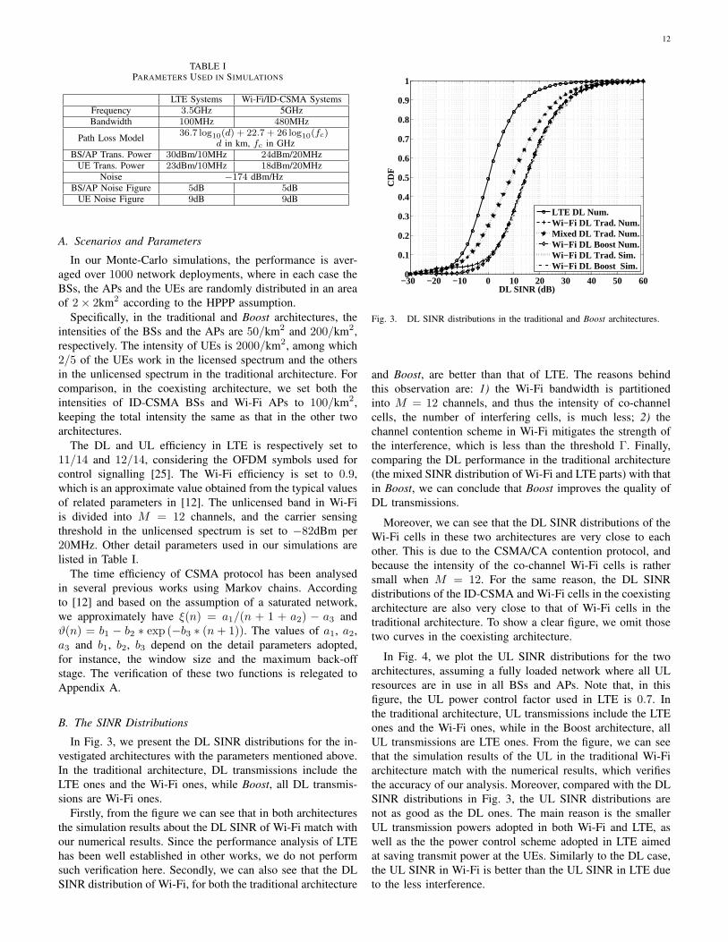
In Fig. 3, we present the DL SINR distributions for the in-vestigated architectures with the parameters mentioned above.In the traditional architecture, DL transmissions include theLTE ones and the Wi-Fi ones, while Boost, all DL transmis-sions are Wi-Fi ones.
Firstly, from the figure we can see that in both architecturesthe simulation results about the DL SINR of Wi-Fi match withour numerical results. Since the performance analysis of LTEhas been well established in other works, we do not performsuch verification here. Secondly, we can also see that the DLSINR distribution of Wi-Fi, for both the traditional architecture
−30 −20 −10 0 10 20 30 40 50 600
0.1
0.2
0.3
0.4
0.5
0.6
0.7
0.8
0.9
1
DL SINR (dB)
CD
F
LTE DL Num.Wi−Fi DL Trad. Num.Mixed DL Trad. Num.Wi−Fi DL Boost Num.Wi−Fi DL Trad. Sim.Wi−Fi DL Boost Sim.
Fig. 3. DL SINR distributions in the traditional and Boost architectures.
and Boost, are better than that of LTE. The reasons behindthis observation are: 1) the Wi-Fi bandwidth is partitionedinto M = 12 channels, and thus the intensity of co-channelcells, the number of interfering cells, is much less; 2) thechannel contention scheme in Wi-Fi mitigates the strength ofthe interference, which is less than the threshold Γ. Finally,comparing the DL performance in the traditional architecture(the mixed SINR distribution of Wi-Fi and LTE parts) with thatin Boost, we can conclude that Boost improves the quality ofDL transmissions.
Moreover, we can see that the DL SINR distributions of theWi-Fi cells in these two architectures are very close to eachother. This is due to the CSMA/CA contention protocol, andbecause the intensity of the co-channel Wi-Fi cells is rathersmall when M = 12. For the same reason, the DL SINRdistributions of the ID-CSMA and Wi-Fi cells in the coexistingarchitecture are also very close to that of Wi-Fi cells in thetraditional architecture. To show a clear figure, we omit thosetwo curves in the coexisting architecture.
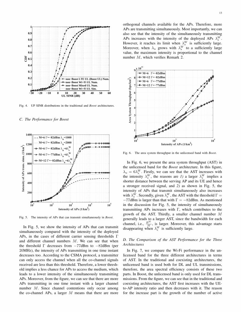
In Fig. 4, we plot the UL SINR distributions for the twoarchitectures, assuming a fully loaded network where all ULresources are in use in all BSs and APs. Note that, in thisfigure, the UL power control factor used in LTE is 0.7. Inthe traditional architecture, UL transmissions include the LTEones and the Wi-Fi ones, while in the Boost architecture, allUL transmissions are LTE ones. From the figure, we can seethat the simulation results of the UL in the traditional Wi-Fiarchitecture match with the numerical results, which verifiesthe accuracy of our analysis. Moreover, compared with the DLSINR distributions in Fig. 3, the UL SINR distributions arenot as good as the DL ones. The main reason is the smallerUL transmission powers adopted in both Wi-Fi and LTE, aswell as the the power control scheme adopted in LTE aimedat saving transmit power at the UEs. Similarly to the DL case,the UL SINR in Wi-Fi is better than the UL SINR in LTE dueto the less interference.
13
−30 −20 −10 0 10 20 30 40 50 600
0.1
0.2
0.3
0.4
0.5
0.6
0.7
0.8
0.9
1
UL SINR (dB)
CD
F
non−Boost LTE UL (Boost UL) Num.non−Boost Wi−Fi UL Num.non−Boost Mixed UL Num.non−Boost Wi−Fi UL Sim.
Fig. 4. UP SINR distributions in the traditional and Boost architectures.
C. The Performance for Boost
101
102
103
104
105
0
200
400
600
800
1000
1200
1400
Intensity of APs (1/km2)
Inte
nsi
ty o
f A
Ps
tra
ns.
sim
u.
(1/k
m2)
M=6 Γ=−82dBm λu=1000
M=6 Γ=−82dBm λu=2000
M=6 Γ=−82dBm λu=6λ
W
s
M=6 Γ=−77dBm λu=6λ
W
s
M=12 Γ=−82dBm λu=6λ
W
s
Fig. 5. The intensity of APs that can transmit simultaneously in Boost.
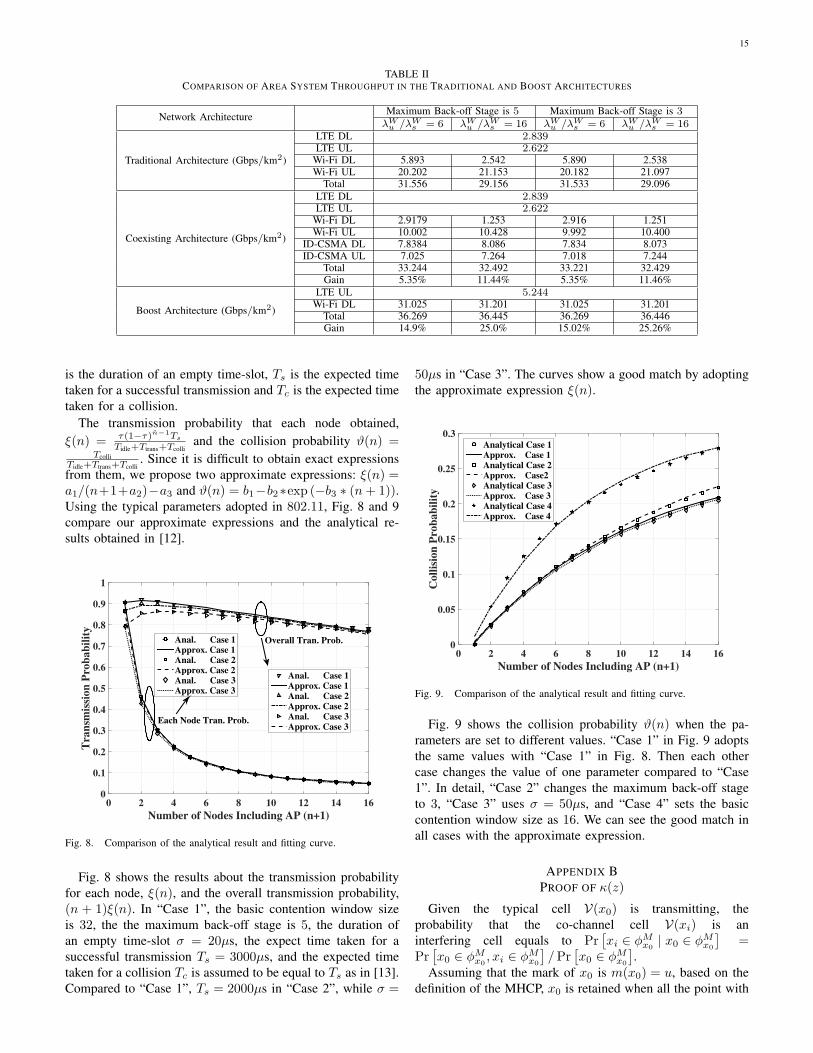
In Fig. 5, we show the intensity of APs that can transmitsimultaneously compared with the intensity of the deployedAPs, in the cases of different carrier sensing thresholds Γand different channel numbers M . We can see that whenthe threshold Γ decreases from −77dBm to −82dBm (per20MHz), the intensity of APs transmitting in one time instantdecreases too. According to the CSMA protocol, a transmittercan only access the channel when all the co-channel signalsreceived are less than this threshold. Therefore, a lower thresh-old implies a less chance for APs to access the medium, whichleads to a lower intensity of the simultaneously transmittingAPs. Moreover, from the figure, we can see that there are moreAPs transmitting in one time instant with a larger channelnumber M . Since channel contentions only occur amongthe co-channel APs, a larger M means that there are more
orthogonal channels available for the APs. Therefore, moreAPs are transmitting simultaneously. Most importantly, we canalso see that the intensity of the simultaneously transmittingAPs increases with the intensity of the deployed APs λW
s .However, it reaches its limit when λW
s is sufficiently large.Moreover, when λu grows with λW
s to a sufficiently largevalue, the maximum intensity is proportional to the channelnumber M , which verifies Remark 2.
102
103
104
0
1
2
3
4
5
6
7
8
9x 10
11
Intensity of APs (1/km2)
Are
a S
yst
em T
hro
ug
hp
ut
(bp
s/k
m2)
M=6 Γ=−82dBm
M=12 Γ=−82dBm
M=6 Γ=−77dBm
M=12 Γ=−77dBm
Fig. 6. The area system throughput in the unlicensed band with Boost.
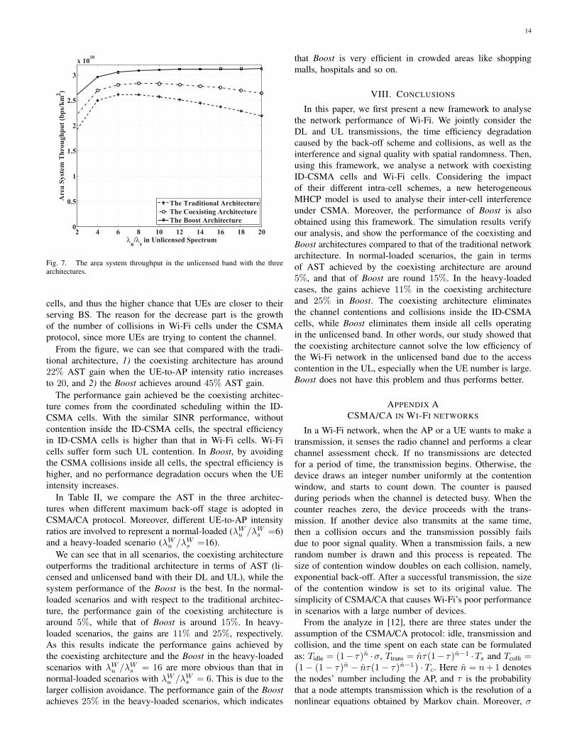
In Fig. 6, we present the area system throughput (AST) inthe unlicensed band for the Boost architecture. In this figure,λu = 6λW
s . Firstly, we can see that the AST increases withthe intensity λW
s , the reasons are 1) a larger λWs implies a
shorter distance between the serving AP and its UE and hencea stronger received signal, and 2) as shown in Fig. 5, theintensity of APs that transmit simultaneously also increaseswith λW
s . Secondly, given λWs , the AST with the threshold Γ =
−77dBm is larger than that with Γ = −82dBm. As mentionedin the discussion for Fig. 5, the intensity of simultaneouslytransmitting APs increases with Γ, which contributes to thegrowth of the AST. Thirdly, a smaller channel number Mgenerally leads to a larger AST, since the bandwidth for eachchannel, i.e., BW
M , is larger. Moreover, this advantage startsdisappearing when λW
s is sufficiently large.
D. The Comparison of the AST Performance for the ThreeArchitectures
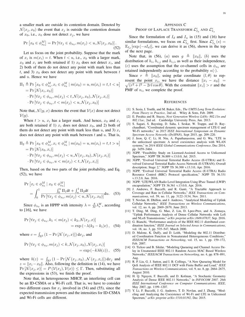
In Fig. 7, we compare the Wi-Fi performance in the un-licensed band for the three different architectures in termsof AST. In the traditional and coexisting architectures, theunlicensed band is used both for DL and UL transmissions,therefore, the area spectral efficiency consists of these twoparts. In Boost, the unlicensed band is only used for DL trans-missions. From the figure, we can see that in the traditional andcoexisting architectures, the AST first increases with the UE-to-AP intensity ratio and then decreases with it. The reasonfor the increase part is the growth of the number of active
14
2 4 6 8 10 12 14 16 18 200
0.5
1
1.5
2
2.5
3
x 1010
λu/λ
s in Unlicensed Spectrum
Are
a S
yst
em T
hro
ug
hp
ut
(bp
s/k
m2)
The Traditional Architecture
The Coexisting Architecture
The Boost Architecture
Fig. 7. The area system throughput in the unlicensed band with the threearchitectures.
cells, and thus the higher chance that UEs are closer to theirserving BS. The reason for the decrease part is the growthof the number of collisions in Wi-Fi cells under the CSMAprotocol, since more UEs are trying to content the channel.
From the figure, we can see that compared with the tradi-tional architecture, 1) the coexisting architecture has around22% AST gain when the UE-to-AP intensity ratio increasesto 20, and 2) the Boost achieves around 45% AST gain.
The performance gain achieved be the coexisting architec-ture comes from the coordinated scheduling within the ID-CSMA cells. With the similar SINR performance, withoutcontention inside the ID-CSMA cells, the spectral efficiencyin ID-CSMA cells is higher than that in Wi-Fi cells. Wi-Ficells suffer form such UL contention. In Boost, by avoidingthe CSMA collisions inside all cells, the spectral efficiency ishigher, and no performance degradation occurs when the UEintensity increases.
In Table II, we compare the AST in the three architec-tures when different maximum back-off stage is adopted inCSMA/CA protocol. Moreover, different UE-to-AP intensityratios are involved to represent a normal-loaded (λW
u /λWs =6)
and a heavy-loaded scenario (λWu /λW
s =16).We can see that in all scenarios, the coexisting architecture
outperforms the traditional architecture in terms of AST (li-censed and unlicensed band with their DL and UL), while thesystem performance of the Boost is the best. In the normal-loaded scenarios and with respect to the traditional architec-ture, the performance gain of the coexisting architecture isaround 5%, while that of Boost is around 15%. In heavy-loaded scenarios, the gains are 11% and 25%, respectively.As this results indicate the performance gains achieved bythe coexisting architecture and the Boost in the heavy-loadedscenarios with λW
u /λWs = 16 are more obvious than that in
normal-loaded scenarios with λWu /λW
s = 6. This is due to thelarger collision avoidance. The performance gain of the Boostachieves 25% in the heavy-loaded scenarios, which indicates
that Boost is very efficient in crowded areas like shoppingmalls, hospitals and so on.
VIII. CONCLUSIONS
In this paper, we first present a new framework to analysethe network performance of Wi-Fi. We jointly consider theDL and UL transmissions, the time efficiency degradationcaused by the back-off scheme and collisions, as well as theinterference and signal quality with spatial randomness. Then,using this framework, we analyse a network with coexistingID-CSMA cells and Wi-Fi cells. Considering the impactof their different intra-cell schemes, a new heterogeneousMHCP model is used to analyse their inter-cell interferenceunder CSMA. Moreover, the performance of Boost is alsoobtained using this framework. The simulation results verifyour analysis, and show the performance of the coexisting andBoost architectures compared to that of the traditional networkarchitecture. In normal-loaded scenarios, the gain in termsof AST achieved by the coexisting architecture are around5%, and that of Boost are round 15%. In the heavy-loadedcases, the gains achieve 11% in the coexisting architectureand 25% in Boost. The coexisting architecture eliminatesthe channel contentions and collisions inside the ID-CSMAcells, while Boost eliminates them inside all cells operatingin the unlicensed band. In other words, our study showed thatthe coexisting architecture cannot solve the low efficiency ofthe Wi-Fi network in the unlicensed band due to the accesscontention in the UL, especially when the UE number is large.Boost does not have this problem and thus performs better.
APPENDIX ACSMA/CA IN WI-FI NETWORKS
In a Wi-Fi network, when the AP or a UE wants to make atransmission, it senses the radio channel and performs a clearchannel assessment check. If no transmissions are detectedfor a period of time, the transmission begins. Otherwise, thedevice draws an integer number uniformly at the contentionwindow, and starts to count down. The counter is pausedduring periods when the channel is detected busy. When thecounter reaches zero, the device proceeds with the trans-mission. If another device also transmits at the same time,then a collision occurs and the transmission possibly failsdue to poor signal quality. When a transmission fails, a newrandom number is drawn and this process is repeated. Thesize of contention window doubles on each collision, namely,exponential back-off. After a successful transmission, the sizeof the contention window is set to its original value. Thesimplicity of CSMA/CA that causes Wi-Fi’s poor performancein scenarios with a large number of devices.
From the analyze in [12], there are three states under theassumption of the CSMA/CA protocol: idle, transmission andcollision, and the time spent on each state can be formulatedas: Tidle = (1− τ)n ·σ, Ttrans = nτ(1− τ)n−1 ·Ts and Tcolli =(1− (1− τ)n − nτ(1− τ)n−1
)·Tc. Here n = n+1 denotes
the nodes’ number including the AP, and τ is the probabilitythat a node attempts transmission which is the resolution of anonlinear equations obtained by Markov chain. Moreover, σ
15
TABLE IICOMPARISON OF AREA SYSTEM THROUGHPUT IN THE TRADITIONAL AND BOOST ARCHITECTURES
Network Architecture Maximum Back-off Stage is 5 Maximum Back-off Stage is 3λWu /λW
s = 6 λWu /λW
s = 16 λWu /λW
s = 6 λWu /λW
s = 16
Traditional Architecture (Gbps/km2)
LTE DL 2.839LTE UL 2.622
Wi-Fi DL 5.893 2.542 5.890 2.538Wi-Fi UL 20.202 21.153 20.182 21.097
Total 31.556 29.156 31.533 29.096
Coexisting Architecture (Gbps/km2)
LTE DL 2.839LTE UL 2.622
Wi-Fi DL 2.9179 1.253 2.916 1.251Wi-Fi UL 10.002 10.428 9.992 10.400
ID-CSMA DL 7.8384 8.086 7.834 8.073ID-CSMA UL 7.025 7.264 7.018 7.244
Total 33.244 32.492 33.221 32.429Gain 5.35% 11.44% 5.35% 11.46%
Boost Architecture (Gbps/km2)
LTE UL 5.244Wi-Fi DL 31.025 31.201 31.025 31.201
Total 36.269 36.445 36.269 36.446Gain 14.9% 25.0% 15.02% 25.26%
is the duration of an empty time-slot, Ts is the expected timetaken for a successful transmission and Tc is the expected timetaken for a collision.
The transmission probability that each node obtained,ξ(n) = τ(1−τ)n−1Ts
Tidle+Ttrans+Tcolliand the collision probability ϑ(n) =
TcolliTidle+Ttrans+Tcolli
. Since it is difficult to obtain exact expressionsfrom them, we propose two approximate expressions: ξ(n) =a1/(n+1+a2)−a3 and ϑ(n) = b1−b2∗exp (−b3 ∗ (n+ 1)).Using the typical parameters adopted in 802.11, Fig. 8 and 9compare our approximate expressions and the analytical re-sults obtained in [12].
Number of Nodes Including AP (n+1)
0 2 4 6 8 10 12 14 16
Tra
nsm
issi
on
Pro
bab
ilit
y
0
0.1
0.2
0.3
0.4
0.5
0.6
0.7
0.8
0.9
1
Anal. Case 1Approx. Case 1Anal. Case 2Approx. Case 2Anal. Case 3Approx. Case 3
Anal. Case 1Approx. Case 1Anal. Case 2Approx. Case 2Anal. Case 3Approx. Case 3
Each Node Tran. Prob.
Overall Tran. Prob.
Fig. 8. Comparison of the analytical result and fitting curve.
Fig. 8 shows the results about the transmission probabilityfor each node, ξ(n), and the overall transmission probability,(n + 1)ξ(n). In “Case 1”, the basic contention window sizeis 32, the the maximum back-off stage is 5, the duration ofan empty time-slot σ = 20µs, the expect time taken for asuccessful transmission Ts = 3000µs, and the expected timetaken for a collision Tc is assumed to be equal to Ts as in [13].Compared to “Case 1”, Ts = 2000µs in “Case 2”, while σ =
50µs in “Case 3”. The curves show a good match by adoptingthe approximate expression ξ(n).
Number of Nodes Including AP (n+1)
0 2 4 6 8 10 12 14 16
Coll
isio
n P
rob
ab
ilit
y
0
0.05
0.1
0.15
0.2
0.25
0.3Analytical Case 1Approx. Case 1Analytical Case 2Approx. Case2Analytical Case 3Approx. Case 3Analytical Case 4Approx. Case 4
Fig. 9. Comparison of the analytical result and fitting curve.
Fig. 9 shows the collision probability ϑ(n) when the pa-rameters are set to different values. “Case 1” in Fig. 9 adoptsthe same values with “Case 1” in Fig. 8. Then each othercase changes the value of one parameter compared to “Case1”. In detail, “Case 2” changes the maximum back-off stageto 3, “Case 3” uses σ = 50µs, and “Case 4” sets the basiccontention window size as 16. We can see the good match inall cases with the approximate expression.
APPENDIX BPROOF OF κ(z)
Given the typical cell V(x0) is transmitting, theprobability that the co-channel cell V(xi) is aninterfering cell equals to Pr
[xi ∈ ϕM
x0| x0 ∈ ϕM
x0
]=
Pr[x0 ∈ ϕM
x0, xi ∈ ϕM
x0
]/Pr
[x0 ∈ ϕM
x0
].
Assuming that the mark of x0 is m(x0) = u, based on thedefinition of the MHCP, x0 is retained when all the point with
16
a smaller mark are outside its contention domain. Denoted byN (xj , x0) the event that xj is outside the contention domainof x0, i.e., x0 dose not detect xj , we have
Pr[x0 ∈ ϕM
x0
]= Pr [∀xj ∈ ϕx0 ,m(xj) < u,N (xj , x0)] .
(52)Let us focus on the joint probability. Suppose that the mark
of xi is m(xi) = t. When t < u, i.e., x0 with a larger mark,x0 and xi are both retained if 1) x0 does not detect xi, and2) both of them do not detect any point with mark less thant, and 3) x0 does not detect any point with mark between tand u. Hence we have
Π1 , Pr[x0 ∈ ϕM
x0, xi ∈ ϕM
x0| m(x0) = u,m(xi) = t, t < u
]= Pr [N (xi, x0)]
· Pr [∀xj ∈ ϕx0 ,m(xj) < t,N (xj , x0),N (xj , xi)]
· Pr [∀xj ∈ ϕx0, t < m(xj) < u,N (xj , x0)]
Note that, N (y, x) denotes the event that V(x) dose not detectV(y).
When t > u, xi has a larger mark. And hence, x0 and xi
are both retained if 1) xi does not detect x0, and 2) both ofthem do not detect any point with mark less than u, and 3) xi
does not detect any point with mark between t and u. That is,
Π2 , Pr[x0 ∈ ϕM
x0, xi ∈ ϕM
x0| m(x0) = u,m(xi) = t, t > u
]= Pr [N (x0, xi)]
· Pr [∀xj ∈ ϕx0 ,m(xj) < u,N (xj , x0),N (xj , xi)]
· Pr [∀xj ∈ ϕx0 , u < m(xj) < t,N (xj , xi)]
Then, based on the two parts of the joint probability, and Eq.(52), we have
Pr[xi ∈ ϕM
x0| x0 ∈ ϕM
x0
]=
∫ 1
0
∫ u
0Π1dt+
∫ 1
uΠ2dt
Pr [∀xj ∈ ϕx0 ,m(xj) < u,N (xj , x0)]du. (53)
Since ϕx0 is an HPPP with intensity λ = AM λW
s , accordingto [16], we have
Pr [∀xj ∈ ϕx0 , k1 < m(xj) < k2,N (xj , x)]
= exp (−λ(k2 − k1)c) , (54)
where c =∫R2 (1− Pr [N (xj , x)]) dxj , and
Pr [∀xj ∈ ϕx0 ,m(xj) < k,N (xj , x0),N (xj , xi)]
= exp (−kλb(z)) , (55)
where b(z) =∫R2 (1− Pr [N (xj , x0) ,N (xj , xi)]) dxj and
z = ∥xi−x0∥. Also, following the definition in (14), we havePr [N (xj , x)] = P (V(xj),V(x)) ≤ Γ. Then, substituting allthe expressions in (53), we finish the proof.
Note that, in heterogeneous MHCP, an interfering cell canbe an ID-CSMA or a Wi-Fi cell. That is, we have to considertwo different cases for xj involved in (54) and (55), since theexpected transmission powers and the intensities for ID-CSMAand Wi-Fi cells are different.
APPENDIX CPROOF OF LAPLACE TRANSFORM Lr
IdAND Lr
Iu
Since the formulation of Id and Iu in (15) and (16) havesimilar formulations, we focus on Lr
Idfirst. Since Lr
Id(s) =
EId [exp (−sId)], we can derive it as (56), shown in the topof the next page.
Note that, in (56), (a) uses g , ∥x0∥, (b) uses thedistribution of hi, hi,j and hi,i, as well as their independence,(c) uses the assumption that the co-channel cells in ϕx0 areretained independently according to the probability κ(·).
Since r , ∥x0∥, using polar coordinate (l, θ) to rep-resent the point xi, we have the distance ∥xi − x0∥ =√
(r2 + l2 − 2rl cos θ). With the constraint ∥xi∥ > r and thePMF of ni, we complete the proof.
REFERENCES
[1] S. Sesia, I. Toufik, and M. Baker, Eds., The UMTS Long Term Evolution:From Theory to Practice, 2nd ed. Wiley & Sons, Feb. 2009.
[2] E. Perahia and R. Stacey, Next Generation Wireless LANs: 802.11n and802.11ac, 2nd ed. Cambridge University Press, Jun. 2013.
[3] S. Sagari, S. Baysting, D. Saha, I. Seskar, W. Trappe, and D. Ray-chaudhuri, “Coordinated dynamic spectrum management of LTE-U andWi-Fi networks,” in 2015 IEEE International Symposium on DynamicSpectrum Access Networks (DySPAN), Sept 2015, pp. 209–220.
[4] J. Jeon, Q. C. Li, H. Niu, A. Papathanassiou, and G. Wu, “LTE inthe unlicensed spectrum: A novel coexistence analysis with WLANsystems,” in 2014 IEEE Global Communications Conference, Dec 2014,pp. 3459–3464.
[5] 3GPP, “Feasibility Study on Licensed-Assisted Access to UnlicensedSpectrum,” 3GPP TR 36.889 v.13.0.0, Jul. 2015.
[6] 3GPP, “Evolved Universal Terrestial Radio Access (E-UTRA) and E-volved Universal Terrestial Radio Access Network (E-UTRAN); Overalldescription; Stage 2,” 3GPP TS 36.300 v.13.3.0, Apr. 2016.
[7] 3GPP, “Evolved Universal Terrestrial Radio Access (E-UTRA) RadioResource Control (RRC) Protocol specification,” 3GPP TS 36.331v.13.2.0, Jun. 2016.
[8] 3GPP, “LTE/WLAN Radio Level Integration Using IPsec Tunnel (LWIP)encapsulation,” 3GPP TS 36.361 v.13.0.0, Apr. 2016.
[9] J. Andrews, F. Baccelli, and R. Ganti, “A Tractable Approach toCoverage and Rate in Cellular Networks,” IEEE Transactions on Com-munications, vol. 59, no. 11, pp. 3122–3134, Nov. 2011.
[10] T. Novlan, H. Dhillon, and J. Andrews, “Analytical Modeling of UplinkCellular Networks,” IEEE Transactions on Wireless Communications,vol. 12, no. 6, pp. 2669–2679, June 2013.
[11] T. Ding, M. Ding, G. Mao, Z. Lin, D. Lpez-Prez, and A. Zomaya,“Uplink Performance Analysis of Dense Cellular Networks with LoSand NLoS Transmissions,” arXiv preprint arXiv:1609.07837, Sep. 2016.
[12] G. Bianchi, “Performance analysis of the IEEE 802.11 distributed coor-dination function,” IEEE Journal on Selected Areas in Communications,vol. 18, no. 3, pp. 535–547, March 2000.
[13] D. Malone, K. Duffy, and D. Leith, “Modeling the 802.11 Distribut-ed Coordination Function in Nonsaturated Heterogeneous Conditions,”IEEE/ACM Transactions on Networking, vol. 15, no. 1, pp. 159–172,Feb. 2007.
[14] O. Tickoo and B. Sikdar, “Modeling Queueing and Channel Access De-lay in Unsaturated IEEE 802.11 Random Access MAC Based WirelessNetworks,” IEEE/ACM Transactions on Networking, no. 4, pp. 878–891,Aug.
[15] R. P. Liu, G. J. Sutton, and I. B. Collings, “A New Queueing Model forQoS Analysis of IEEE 802.11 DCF with Finite Buffer and Load,” IEEETransactions on Wireless Communications, vol. 9, no. 8, pp. 2664–2675,August 2010.
[16] H. Q. Nguyen, F. Baccelli, and D. Kofman, “A Stochastic GeometryAnalysis of Dense IEEE 802.11 Networks,” in INFOCOM 2007. 26thIEEE International Conference on Computer Communications. IEEE,May 2007, pp. 1199–1207.
[17] Y. Li, F. Baccelli, J. G. Andrews, T. D. Novlan, and J. Zhang, “Mod-eling and Analyzing the Coexistence of Wi-Fi and LTE in UnlicensedSpectrum,” arXiv preprint arXiv:1510.01392, Dec 2015.
17
EId
exp−s
∑xi∈ϕI
x0
LW0 ∥xi∥−αW
ξ(ni)PWs hi +
ni∑j=1
ξ(ni)PWu hi,j + ϑ(ni)2
niPWu + PW
s
ni + 1hi,i
(a)= Exi,ni,hi,hi,j ,hi,i
[∏xi
(exp
(−sLW
0 g−αW
ξ(ni)PWs hi
)exp
(−sLW
0 g−αW
ϑ(ni)2niP
Wu + PW
s
ni + 1hi,i
)ni∏j=1
exp(−sLW
0 g−αW
ξ(ni)PWu hi,j
)(b)= Exi,ni
∏xi∈ϕa
x0
1(1 + sξ(ni)PW
s LW0 g−αW
) · 1(1 + sϑ(ni)P col
xiLW0 g−αW
) ·(
1
1 + sξ(ni)PWu LW
0 g−αW
)ni
(c)≈ Eni
[exp
(−AλW
s
M
∫R2
κ (∥xi − x0∥)(1− 1
1 + sξ(ni)PWs LW
0 g−αW · 1
1 + sϑ(ni)P colxi
LW0 g−αW
· 1(1 + sξ(ni)PW
u LW0 g−αW
)ni
)dxi
)].
(56)
[18] J. Ling, S. Kanugovi, S. Vasudevan, and A. K. Pramod, “EnhancedCapacity & Coverage by Wi-Fi LTE Integration,” IEEE Comm. Mag.,vol. 53, no. 3, pp. 165–171, Mar. 2014.
[19] Nokia. (2015, Mar.) Wireless Unified Networks. [Online]. Available:https://networks.nokia.com/press/2015/alcatel-lucent-combines-best-wi-fir-and-lte-enhance-mobile-performance-and-offer-consistent-high
[20] B. Yu, L. Yang, H. Ishii, and S. Mukherjee, “Dynamic TDD Support inMacrocell-Assisted Small Cell Architecture,” IEEE Journal on SelectedAreas in Communications, vol. 33, no. 6, pp. 1201–1213, June 2015.
[21] S. Lee and K. Huang, “Coverage and Economy of Cellular Networkswith Many Base Stations,” IEEE Communications Letters, vol. 16, no. 7,pp. 1038–1040, July 2012.
[22] M. Haenggi, Stochastic Geometry for Wireless Networks. CambridgeUniversity Press, 2012.
[23] M. Iwamura, K. Etemad, M. h. Fong, R. Nory, and R. Love, “Carrieraggregation framework in 3GPP LTE-advanced [WiMAX/LTE Update],”IEEE Communications Magazine, vol. 48, no. 8, pp. 60–67, August2010.
[24] H. S. Jo, Y. J. Sang, P. Xia, and J. G. Andrews, “Heterogeneous CellularNetworks with Flexible Cell Association: A Comprehensive Down-link SINR Analysis,” IEEE Transactions on Wireless Communications,vol. 11, no. 10, pp. 3484–3495, October 2012.
[25] 3GPP, “Evolved Universal Terrestial Radio Access; Further Enhance-ments for E-UTRA physical layer aspects,” 3GPP TR 36.872 v.9.0.0,Mar. 2010.
Youjia Chen received the B.S. and M.S degrees incommunication engineering from Nanjing Universi-ty, Nanjing, China, in 2005 and 2008, respectively.From 2008-2009, she worked in Alcatel LucentShanghai Bell. From Aug. 2009 until now, sheworks at the College of Photonic and ElectricalEngineering, Fujian Normal University, China. Sheis currently pursuing the Ph.D. degree in wirelessengineering at The University of Sydney, Australi-a. Her current research interests include resourcemanagement, load balancing, and caching strategy
in heterogeneous cellular networks.
Ming Ding (M’12) received the B.S. and M.S.degrees (with first class Hons.) in electronics engi-neering from Shanghai Jiao Tong University (SJTU),Shanghai, China, and the Doctor of Philosophy(Ph.D.) degree in signal and information processingfrom SJTU, in 2004, 2007, and 2011, respectively.From September 2007 to September 2011, he pur-sued the Ph.D. degree at SJTU while at the sametime working as a Researcher/Senior ResearcherSharp Laboratories of China (SLC). After achievingthe Ph.D. degree, he continued working with SLC
as a Senior Researcher/Principal Researcher until September 2014, when hejoined National Information and Communications Technology Australia (NIC-TA). In September 2015, Commonwealth Scientific and Industrial ResearchOrganization (CSIRO) and NICTA joined forces to create Data61, where hecontinued as a Senior Research Scientist in this new R&D centre located inSydney, N.S.W., Australia. He has authored about 40 papers in IEEE journalsand conferences, all in recognized venues, and about 20 3GPP standardizationcontributions, as well as a Springer book Multi-point Cooperative Communi-cation Systems: Theory and Applications. Also, as the first inventor, he holdsfifteen CN, seven JP, three US, two KR patents and co-authored another100+ patent applications on 4G/5G technologies. He is or has been GuestEditor/Co-Chair/TPC member of several IEEE top-tier journals/conferences,e.g., the IEEE Journal on Selected Areas in Communications, the IEEECommunications Magazine, and the IEEE Globecom Workshops. For hisinventions and publications, he was the recipient of the President’s Awardof SLC in 2012, and served as one of the key members in the 4G/5Gstandardization team when it was awarded in 2014 as Sharp Company BestTeam: LTE 1014 Standardization Patent Portfolio.
18
David Lopez-Perez (M’12) is a Member of Techni-cal Staff at Nokia Bell Laboratories, and his main re-search interests are in HetNets, small cells, massiveMIMO, interference and mobility management aswell as network optimization and simulation. Prior tothis, David earned his PhD in Wireless Networkingfrom the University of Bedfordshire, UK in Apr. ’11,and obtained his BSc and MSc degrees in Telecom-munication from the Miguel Hernandez University,Spain in Sept. ’03 & Sept. ’06, respectively. Davidwas Research Associate at King’s College London,
UK from Aug. ’10 to Dec. ’11, carrying post-doctoral studies, and was withVODAFONE, Spain from Feb. ’05 to Feb. ’06, working in the area of networkplanning and optimization. For his publications and patent contributions,David is a recipient of both the Bell Labs Alcatel-Lucent Award of Excellence(2013) and Certificate of Outstanding Achievement (2013, 2014, 2015). Hewas also finalist for the Scientist of the Year prize in The Irish LaboratoryAwards (2013, 2015). David has also been awarded as PhD Marie-CurieFellow in 2007 and Exemplary Reviewer for IEEE Communications Letters in2011. David is author of the book ”Heterogeneous Cellular Networks: Theory,Simulation and Deployment” Cambridge University Press, 2012. Moreover,he has published more than 90 book chapters, journal and conference papers,all in recognized venues, and filed more than 30patents applications. Davidis or has been guest editor of a number of journals, e.g., IEEE JSAC, IEEEComm. Mag., and TPC member of top tier conferences, e.g., IEEE Globecomand IEEE ICC.
Zihuai Lin (S’98-M’06-SM’10) received the Ph.D.degree in Electrical Engineering from Chalmers U-niversity of Technology, Sweden, in 2006. Prior tothis he has held positions at Ericsson Research,Stockholm, Sweden. Following Ph.D. graduation,he worked as a Research Associate Professor atAalborg University, Denmark and currently at theSchool of Electrical and Information Engineering,the University of Sydney, Australia. His research in-terests include source/channel/network coding, cod-ed modulation, MIMO, OFDMA, SC-FDMA, radio
resource management, cooperative communications, small-cell networks, 5Gcellular systems, etc.
Guoqiang Mao (S’98-M’02-SM’08) received PhDin telecommunications engineering in 2002 fromEdith Cowan University. He was with the Schoolof Electrical and Information Engineering, the U-niversity of Sydney between 2002 and 2014. Hejoined the University of Technology Sydney inFebruary 2014 as Professor of Wireless Networkingand Director of Center for Real-time InformationNetworks. The Center is among the largest universityresearch centers in Australia in the field of wirelesscommunications and networking. He has published
about 200 papers in international conferences and journals, which have beencited more than 4000 times. He is an editor of the IEEE Transactionson Wireless Communications (since 2014), IEEE Transactions on VehicularTechnology (since 2010) and received Top Editor award for outstandingcontributions to the IEEE Transactions on Vehicular Technology in 2011,2014 and 2015. He is a co-chair of IEEE Intelligent Transport Systems SocietyTechnical Committee on Communication Networks. He has served as a chair,co-chair and TPC member in a large number of international conferences. Hisresearch interest includes intelligent transport systems, applied graph theoryand its applications in telecommunications, Internet of Things, wireless sensornetworks, wireless localization techniques and network performance analysis.