Embed Size (px)
Citation preview

A STUDY OF COMPARING CAD/CAM SIMULATED MACHINING TIME WITH
PRACTICAL CNC MACHINING TIME AND THE INFLUENCE OF THE PARAMETER SETTING IN CNC
__________________________
A Thesis
Presented to
the Faculty of the College of Business and Technology
Morehead State University
_________________________
In Partial Fulfillment
of the Requirements for the Degree
Master of Science
_________________________
by
Jinming Wan
July 11, 2018

ProQuest Number:
All rights reserved
INFORMATION TO ALL USERSThe quality of this reproduction is dependent upon the quality of the copy submitted.
In the unlikely event that the author did not send a complete manuscriptand there are missing pages, these will be noted. Also, if material had to be removed,
a note will indicate the deletion.
ProQuest
Published by ProQuest LLC ( ). Copyright of the Dissertation is held by the Author.
All rights reserved.This work is protected against unauthorized copying under Title 17, United States Code
Microform Edition © ProQuest LLC.
ProQuest LLC.789 East Eisenhower Parkway
P.O. Box 1346Ann Arbor, MI 48106 - 1346
10843469
10843469
2018

Accepted by the faculty of the College of Business and Technology, Morehead State University, in partial fulfillment of the requirements for the Master of Science degree.
____________________________ Dr. Qingzhou Xu Director of Thesis
Master’s Committee: ________________________________, Chair Dr. Ahmad Zargari
_________________________________ Dr. Qingzhou Xu
_________________________________
Dr. Nilesh Joshi
________________________ Date

A STUDY OF COMPARING CAD/CAM SIMULATED MACHINING TIME WITH PRACTICAL CNC MACHINING TIME AND THE INFLUENCE OF THE PARAMETER
SETTING IN CNC
Jinming Wan Morehead State University, 2018
Director of Thesis: __________________________________________________
Dr. Qingzhou Xu CNC machining is characterized by high precision, efficiency, and reliability, which
make it the popular choice in the manufacturing industry. It can satisfy the diverse, quickly-
changing market needs. The integration of CAD/CAM with CNC makes the machining process
simpler and more convenient. Specifically, the 3D visualization and simulation in CAD/CAM
software significantly reduce the design time and help identify earlier any incorrect processing
step in the practical CNC machining.
Nevertheless, there is still a strong demand to improve the integration of CAD, CAM and
CNC to achieve even more efficient CNC machining. To realize this goal, the following
problems need to be addressed. First, the current CNC machining program has many parameters,
which generate a huge number of parametric combinations, making it difficult for an operator to
do correct machine settings, especially for a beginner. Second, the software’s simulated results
cannot truly reflect the practical machining process, resulting in the vast number of trials in order

to seek the machine setting and consequently causing the increasing cost for the real production
process. Third, because the CAD/CAM software does not include many key factors that affect
the CNC machining process, it cannot reveal the actual machining process.
This research compares the simulated machining time with the practical machining time
in order to figure out whether the CAD/CAM software can reflect the practical machining
process. Meanwhile, the design of experiments is used to discover what kind of influences the
tool paths present in machining time and tool life and how cutting tools affect the machining
processes. Through such a systematic approach, this research is able to identify the optimal
parameters for the practical CNC machining.
In conclusion, the CAD/CAM software cannot accurately reflect the situation of a
practical CNC machining process. To prevent tool wear, the tool path should avoid abrupt turns
and thus prevent the generation of severe cutting forces. For the same machining geometry,
different tool paths need to use different cutting tools to get desirable results. Specifically, the
outside cutting method needs to use large-diameter cutting tools with more flutes while the inside
cutting method should use small diameter cutting tools with fewer flutes to take chips away.
Accepted by: ______________________________, Chair
Dr. Ahmad Zargari
______________________________ Dr. Qingzhou Xu
______________________________ Dr. Nilesh Joshi

ACKNOWLEDGEMENT
I would like to express my deep gratitude to the members of the thesis defense committee,
Dr. Ahmad Zargari, Dr. Qingzhou Xu, and Dr. Nilesh Joshi. I thank them for their help and
guidance they gave to me. I have learned a lot from them during the two years. I am glad to be
their student. I would like to extend my sincere gratitude to Mr. Sam Mason for his great
assistance to me on CNC machining. Without his help, I could not have gained so much
knowledge on CNC. I would like to thank Mr. Jason Stepp for his help in labs. My education at
Morehead State University would be the most precious asset in my entire life. Thanks all of you
very much!

Table of content
Chapter 1-Introduction .................................................................................................................1
1.1 Background and History of Manufacturing Industry ......................................................1
1.2 CAD/CAM and CNC ...........................................................................................................2
1.3 General Concern ..................................................................................................................4
1.4 The Purpose of the Research ..............................................................................................6
1.5 Objectives..............................................................................................................................9
Chapter 2-Literature Review ......................................................................................................10
2.1 Tool Life ..............................................................................................................................10
2.2 Tool Wear ...........................................................................................................................12
2.3 Factors Affect the CNC Machining Process ....................................................................13
2.4 Parameters in the CAD/CAM System..............................................................................20
Chapter 3-Methodology...............................................................................................................22
3.1 Problem Restatement ........................................................................................................22
3.2 Experiment Set-up and Instrument .................................................................................23
3.21 Instrument ...................................................................................................................24
3.22 Software Simulation ....................................................................................................27
Chapter 4- Data Collection and Analysis...................................................................................34
4.1 Difference Between Practical and Simulated Machining Time ....................................38
4.2 Tool Path Comparing .......................................................................................................40
4.3 Cutting Tool Comparing ..................................................................................................42
4.4 Failed Machining ...............................................................................................................43
Chapter 5- Conclusion and Future Research ............................................................................45
References .....................................................................................................................................47

1
Chapter 1-Introduction
1.1 Background and History of Manufacturing Industry
The competition in the manufacturing industry has reached an unparalleled level, especially
with traditional, heavy manufacturing sectors. During globalization, some companies focusing
on local services have faded away. In contrast, the existing manufacturing corporations are those
who desire to optimize their inharmonic production structure in order to adapt to a global market,
reduce their superfluous raw materials and unnecessary staff to control the cost, and enhance
their productivity. Nowadays, the drastic change in the globalization of the manufacturing
industry is not the horn of the finale but just the sparkle of the start. Manufacturing firms need to
cope with the increasing market challenges to gratify the various demands of the trade market,
such as high quality, diversity, portability, and low cost.
Those challenges caused by the competitive market are not only threats but also
opportunities for the manufacturing industry. Generally, they can force corporations to enter into
a more opened international market in order to expand their scale of operation, improve the
management system, reduce the cost, and promote technical development. As far as technical
development is concerned, traditional manual operation or semi-mechanization is replaced by
automation jobs due to high efficiency and low material usage; manual drawing design is
replaced by 3-D design due to visualization and automation. Such technical renovation is an
inevitable procedure to stay in a line with the market rules and to march toward success. The
reason why technical renovations occupy an indispensable position is that the technical
renovation sets the course of products, determines a pattern of production, and optimizes the
system structure. Specifically, a modernization manufacturing company reforming its traditional

2
technology, such as replacing the obsolete machine by an automated facility, will focus on a
broad market, mass production, and the knowledge of staff not the manual skill of labor.
The Industrial Revolution has been an epoch-making event for the whole world and a
milestone in the manufacturing industry. It is an indisputable fact that technology plays a vital
role in the manufacturing industry. Since the computer was invented, the relationship between
the computer and the manufacturing industry has become closer and closer. This situation has
become increasingly intense, and the manufacturing industry can no longer survive without
computer automation. The reason is that mass production has become an irresistible trend in the
manufacturing industry. Mass production needs a rapid, accurate, repetitive, and stable
production model, which can adapt to the fast industrial development. In this situation, computer
tools and software have arisen in order to respond to the contemporary needs, tools and softwares
such as Computer Numerical Control (CNC), Computer-Aided Manufacturing (CAM),
Computer-Aided Design (CAD), Flexible Manufacturing Systems (FMS), Analysis-Led Design
(ALD), Computer-Aided Engineering (CAE), Computational Fluid Dynamics (CFD), Design of
Experiments (DOE), Finite Element Analysis (FEA), Information Technology (IT), and
Computer Integrated Manufacturing (CIM).
1.2 CAD/CAM and CNC
Computer tools and software benefit from the development of certain technological
advancements, especially computer science. Due to the sweeping globalization wave, the
integration among different computer tools becomes an irresistible trend to help make up the
shortfall and/or further improve the performance. On this occasion, the manufacturing industry
integrates the CAD and CAM to be a more efficient method for product design and process
manufacturing. With this approach, the manufacturing industry can simplify the two steps,

3
product design and process manufacturing, into one single package for producing. The
simplification is not just making two packages into one package but is more like creating a new
platform to research and develop products in an integrated view. As a result, the whole process
features short design time, better structure, and convenient machining. More specifically, the
CAD/CAM system proves that the integration of CAD and CAM adapts to today’s
manufacturing. Hence, the discussion of the practical system not only gives this research a
theoretical value but also gives practical significance.
Computer Numerical Control (CNC) is the automatic process controlled by the computer to
control machine tools to execute given commands which are programmed by specific machine
languages. In 1952, Massachusetts Institute of Technology (MIT) built the first 3-axis CNC
machine, which began a new era. Since then, the CNC machine has begun to be an indispensable
device in the modern manufacturing industry. Nowadays the CNC machine has been developed
to fulfill precise, complicated, fast, and repeatable performance by CNC programming control
system significantly improving productivity. The operator can code the CNC programming
control system to rapidly change the machine tool path in order to achieve a new stable
production pattern. That makes the CNC machine able to fulfill multifunction but does not limit
it to one single production mode in a short time to adapt to diversity and a quickly-changing
market.
Another compelling aspect of CNC is the integration with CAD/CAM system. The
integration makes CNC able to directly utilize an existing computer 3D model and generates
CNC tool paths in the CNC machine by CNC machine programming system. Concretely
speaking, a designer utilizes CAD software to generate a certain computer geometric model and
then translate the computer geometric model to a specific package that can be read by the

4
specific CAM software. After receiving the data from the CAD package, the CAM system will
generate a tool path to guide the CNC machine to produce the computer geometric model. In the
modern manufacturing industry, five steps are required to completely execute the product’s
manufacturing process.
(1) Product specification and requirement. This step is paramount to the whole product
manufacturing process. The designer who decides the production design relies on these
parameters.
(2) Generating a certain computer geometric model. In this step, the designer creates a
proper visualization model that can satisfy the demands.
(3) Planning manufacturing process. In planning manufacturing process, the designer
utilizes the visualization geometric model to generate the tool path and then to simulate and
verify the manufacturing process.
(4) Generating G-code or M-code. The CNC machine uses either G-code or M-code for its
programming language. In this step, the CAD/CAM system generates the G-code or M-code and
sends them to the CNC machine.
(5) Machining the product. The CNC machine receives the G-code and performs it to
machine the desired product.
1.3 General Concern
Though the integration of CAD/CAM and CNC is efficient, the disadvantages cannot be
ignored. The integration between CAD/CAM and CNC indeed simplifies the whole industry
processing by the means of process calculation and result simulation in computer software.
However, the manufacturing process is a comprehensive and complex production process, and
even with the convenience of the new digital age, it is unable to fully handle the whole process.

5
Nowadays the CNC machining process manipulated by machining programing language relieves
the operator’s workload and reduces the working time. Besides that, the machining process has
high precision and repeatability. All these benefits of CNC machine derive from hi-tech
automation and the whole machining processes can be changed by the CAD/CAM system to
acquire the desired outcome. Unfortunately, no CAD/CAM software has the ability to optimize
the overall process automatically. All parameters in the CAD/CAM system must be selected
manually one by one to determine the terminal machining process. Therefore, the combination of
multiple parameters in the CAD/CAM system is enormous and only an experienced expert can
select relatively proper parameters. Another considerable aspect impairing manufacturing
process in practical CNC machining is tool wear.
Realizing the full potential of the CNC machine depends upon the use of reliable high-
efficiency cutting tools to produce accurate parts at prices that make the machining process
competitive (Ibrahim, 2005). Thus, how to extend tool life is a persistent topic being researched
for the sake of reducing cost, raising productivity, and ensuring acceptance. In fact, tool wear is
an inevitable outcome happening in all workpiece processes but it does not mean that the tool
wear is not a significant factor to be considered in the practical manufacturing process. In
significant contrast, tool wear as one of the vital factors plays an indispensable role in deciding
the product quality and productivity, affecting the whole manufacturing process economical
efficiency. In a brief summary, on the effect of multiple parameters and incomplete realistic
conditions, CAD/CAM software is variable, nonlinear, and complicated. For instance, the tool
life should be analyzed in CAD/CAM software calculation and simulation because tool life plays
a significant role in metal machining as it guarantees surface quality and economics of cutting
operations in end milling (Gokulachandran & Mohandas, 2015). Tool wear, thermal generation,

6
chips, and cutter friction force are also important to CNC machining in the practical
manufacturing process. Understanding the relationship between tool life, tool wear, and time
reduction can efficiently improve the total productivity in practical manufacturing. Moreover,
parameter setting will result in a striking difference in the whole CNC machining process,
consequently leading to a vast difference to the product like quality and productivity, such as cut
depth, type of tool path, cutter diameter, type, material, and length, either subtly or significantly.
1.4 The Purpose of the Research
Base on the limitations discussed above, this research mainly targets how to improve the
CNC machining process efficiency to reduce wasted time and discuss the relationship between
extending tool life span and reducing machining time. Normally, modern CNC machining
process is controlled by programming languages like G-code and/or M-code in order to fulfill its
performance in automatic production. Programming CNC machine languages, however, is a
tedious and complex process replaced by the computer to relieve engineer’s labor and improve
productivity. Nowadays, the majority of operators have no need to program the tedious CNC
machine code to guide the whole machining process in order to generate their ideal tool path.
Fortunately, in the CAD/CAM system, a designer can decide the complete CNC machining
process just by setting different parameters, which can effectively reduce the time, thereby
increasing productivity. Nevertheless, the CAD/CAM system is efficient; the infinite possibility
of machining process generates routes by plentiful parameter settings and variety of tool path.
For this reason, this research mainly aims at some significant parameter settings to help
operators acquire an idea to figure out favorable machining process in order to reduce machining
time and improve productivity. The method to find the way to improve CNC machining
processes is to utilize CAD/CAM system in order to select different parameters to form different

7
combinations and consequently obtain different CNC machining results. Meanwhile, the
researcher compares and simulates the CNC machining process for the sake of quickly acquiring
the virtualized digital data as a reference to help optimize the practical CNC machining process.
Moreover, some parameters in the CAD/CAM system do affect the machining process but
cannot fully present their influence in CAD/CAM software. For example, feed rate, cutting speed,
and depth of cut affect machining time as well as tool wear. Tool wear contributes significantly
not only to the final cost but also to the surface quality (Wang, 2012). Therefore, the parameter
setting in CAD/CAM software should not be blindly selected to obtain a good theoretical result
but connect to the practical machining process to obtain a meaningful and appropriate result.
The operator cannot fully rely on the simulation of CAD/CAM software because the result
is based on an ideal situation significantly different from practical processing. Under the ideal
environmental machining process, a simulated result normally works like a mathematical model
to present some important machining information, such as tool path, feed length, spindle speed,
feed rate, feed time, rapid length, rapid time, total length, and total machining time. It is an
undeniable fact that the simulated result of CAD/CAM software can effectively indicate tool
trajectory and machining parameters. Nevertheless, the practical machining process is more
complicated than the simulated result. Meanwhile, a great number of conditions ignored by
CAD/CAM software may ultimately ruin the whole machining process, which could cause
serious damages to the workpiece, tool, and even the CNC machine. In any of the above
situations, it would be an unnecessary loss to the company due to thoughtful consideration.
Generally speaking, a CNC machine crash does not happen easily but workpiece and tool
damage can happen easily and should receive attention. In fact, CAD/CAM software cannot
simulate the actual machining process so the final status of workpiece and tool also cannot be

8
presented or be partly presented. Specifically, the cutting speed and feed rate both can
significantly affect the machining process. Therefore, any inappropriate cutting speed or feed
rate will cause workpiece scratch and/or tool wears, consequently, resulting to defective products
and low productivity. In CAD/CAM simulation, however, the value of cutting speed and feed
rate change only reflects the machining time change but not the whole process. As a consequence,
CAD/CAM simulation works without significant differences even when the operator sets an
unreasonable value for the cutting condition, but practical machining might crash due to
unreasonable parameter settings. Cutting speed and feed rate as required parameters forced to be
set in CAD/CAM software make the simulated machining process different than practical
machining process, let alone other parameters that are not listing in CAD/CAM software. Take
chip as an example; the workpiece and tool will generate a lot of heat, which destroys surface
finish and dulls tool increasingly fast for the reason of chip clogging if chips cannot be taken
away from workpiece or tool.
From the quick examples given above, the disadvantages of CAD/CAM software are
covered all at a glance. First, the gargantuan parameter setting of CNC machining makes infinite
combinations of the machining process, leading to difficulty in making selections, which may
frustrate of beginners. Second, the software simulated result cannot truly reflect the practical
machining process, consequently resulting in the vast practical testing and further causing the
increasing cost in order to seek a better method for the real production process. Third, the
CAD/CAM software not including factors that affect the CNC machining process cannot reveal
the actual machining process. In conclusion, the CAD/CAM software shows its disadvantages on
calculation and simulation for the practical machining process. It is undoubted that any
theoretical calculation cannot utterly match practical complicated system especially for that

9
software cannot deal with the instantaneous reaction. Generally speaking, the CNC machining
process is running in a non-constant environment, resulting in the changes in some presetting
parameters and further leading to deviation comparing with ideal condition and result.
Meanwhile, the vast majority of CAD/CAM software programs cannot instantly make
adjustment along with the change of surrounding circumstances. Therefore, it is necessary to
detect the difference between the calculation and simulation in CAD/CAM software and the
performance of the practical machining process.
1.5 Objectives
This paper aims to achieve the following objectives:
1. Review the current machining process to figure out the advantages and disadvantages.
2. Optimize the selection of tool path, cutter diameter, cut depth, and the number of tool
teeth to reduce the time of CNC machining.
3. Compare the practical machining time with the CAD/CAM simulated machining time

10
Chapter 2-Literature Review
2.1 Tool Life
The life of the tool is the time in which it can perform satisfactorily for given cutting
conditions (Thakare, 2007). The productivity in terms of machining cost, machining operation,
and quality of the workpiece and its integrity strongly depends on tool wear and consequently, it
depends on the life of the tool (Gokulachandran, 2015). The main benefit of extending tool life is
reducing the cost and improving productivity. Extending tool life can significantly improve
efficiency by decreasing tool exchange frequency and ensure quality to products. There are many
factors affecting tool life span or causing tool wear, such as cut material, cutting force, cut chips,
cut depth, thermal generation, feed rate, cutting speed, spindle speed, cutting fluid and so forth.
Although prolonging tool life is beneficial, the whole economy should be considered. A simple
example known to machinists to prolong tool life and reduce thermal generation is lowering
cutting speeds and feeds to reduce cutting force. However, low cutting speeds and feeds decrease
the productivity and increase the machining time. Dropping machining time as an efficient way
to boost productivity, and cutting down cost is a basic need in the manufacturing industry. In fact,
too many conflicting factors happening in the machining process converge together to make the
whole process increasingly complicated. For those reasons, it is an uneconomical and
unacceptable attempt to unilaterally extend tool life or reduce machining time. All in all, the
conditions result in a very short tool life. This is uneconomical because the cost of tool grinding
and tool replacement is high. On the other hand, the use of very low speeds and feeds to give
long tool life is uneconomical because of the low production rate (Ibrahim, 2005). How to decide
the balance between tool life and time reduction is a long-term and significant objective in the
manufacturing industry.

11
Generally, tool life is the period of practical machining time from a brand new cutting tool
until of tool failure. Prolonging tool life, therefore, largely depends on preventing tool failure.
Tool failure, typically, happens in three modes:
1. Temperature failure. Cutting edges have been dulled due to plastic deformation and
thermal stress in high temperatures.
2. Mechanical breakage. Tool or cutting edge is broken due to mechanical impact in the
condition of undue cutting force.
3. Gradual cutting tool failure. In the manufacturing industry, the gradual cutting tool
failure, normally called tool wear, is an inevitable process in regular operation and cannot be
prevented but it can be retarded. Tool wear happens in its flanks (flank wear) and rake (crater
wear) surface.
In these three modes of tool failure, temperature failure and mechanical breakage are
significantly detrimental to the workpiece and cutting tools. Once those two kinds of tool failure
occur, the whole machining process is a failure. For example, temperature failure sometimes
results in the workpiece melting and consequently covering the cutting edge due to high
temperatures. Even worse, keeping the CNC machine running will lead to the temperature rising
even higher. Finally, both the cutting tool and workpiece crash because they are unable to
withstand high temperature and inappropriate mechanical impact. Therefore, the temperature
failure and mechanical breakage should be avoided as far as possible. Normally selecting
appropriate cutting tool material, tool geometry, workpiece material, and cutting parameters can
efficiently decrease significant tool failure.

12
2.2 Tool Wear
In distinct contrast, tool wear is an unavoidable machining process gradually generating
wear in the machining process. Although tool wear is inevitable, tool wear can be slowed down
effectively by means of adjusting speeds, feeds, depth of cut, coolant, chip cleaning and so forth.
According to Diniz, Machado, & Corrêa (2016), the causes of tool wear include attrition wear,
abrasion wear, diffusion wear, chemical wear, and thermal and/or load variation and so on.
a. Attrition Wear: Called adhesion wear in some articles, attrition wear exists in the whole
machining process in the condition of workpiece material rubbing with tool surface with a
certain degree of temperature and pressure rising. Attrition wear is more likely to happen at low
cutting speeds because removed workpiece material is pressed to the cutting tool surface.
Continuous and newly removed workpiece materials, meanwhile, partly scour out adhesive
material leading to an uneven area with abundant cracks. Furthermore, diffusion and chemical
tool wears become dominant over attrition tool wear under the condition of higher cutting speeds.
The detriment of attrition/adhesion tool wear will cause interrupted machining process and
cutting tool vibration.
b. Abrasion Wear: The plucked-off particles from the tool substrate and hard abrasive
carbide particles contained in the nickel-based alloys were mainly found responsible for abrasion
wear (Akhtar et al, 2014). When the cutting tool edge is rubbing, softer substrate makes contact
with hard constituent causing significant abrasion tool wear with low cutting speed.
c. Diffusion Wear: The mechanism of diffusion tool wear is that the higher concentration
of cutting tool atoms diffuses into the workpiece or chip in a high-temperature situation. Hence,
the diffusion wear is the dark, burned appearance in the cutting tool edge especially in the
interface between tool and chips. This type of tool wear normally takes place at high cutting

13
speed.
d. Chemical Wear: Chemical wear is a kind of tool wear due to the chemical reaction
between tool material and the ambient reactant such as workpiece material and/or cutting fluid.
Chemical wear happens because the chemical stability of cutting tool material is not strong
enough to prevent the chemical reaction from ambient reactant under certain condition especially
like high temperature and/or chemical active cutting fluid. This kind of tool wear leads to tool
surface generating pores and grooves and eventually causes the cutting tool to have its original
properties weakened.
e. Thermal and/or Loading Vibration: This type of tool wear takes place when cyclical
thermal stress and/or mechanical loading and unloading act on cutting tools. This type of tool
wear is transverse crack and gives rise to chipping of the tool.
According to Akhtar et al (2014), all types of cutting tool wears, such as attrition wear,
abrasion wear, diffusion wear, chemical wear, and thermal and/or load variation, happen in
different kinds of machining conditions, and all kinds of tool wears are not independent but
combining together to generate tool failure.
2.3 Factors Affect the CNC Machining Process
As mentioned above, the cutting tool, playing an important role in CNC machining process,
restrict the behavior of machining and the efficiency of operations so the affected factors of tool
life should be paid attention to for the sake of optimizing the machining process. Many factors
resulting in tool wear which shortens tool life. Furthermore, these factors are not isolated but mix
together to affect the machining performance in a comprehensive approach. Therefore,
understanding every relevant factor in the machining process is a long-term and arduous job. As

14
a result, this investigator just briefly reviews the recent researches about the relationship between
the tool life and some key factors.
Different factors play different roles in the influence of tool life. Some of them are
significant but some of them are marginal. Some factors not only influence tool life but also
impact the other machining performances in the machining process, such as machining time and
surface quality. For example, the high temperature during machining causes thermal softening of
the workpiece, which in turn reduces the cutting forces at the cutting zone. The reduction of
cutting forces is desirable but the excessive temperature causes thermal damage on the machined
surface and also softens the cutting edges, thus resulting in poor surface quality (Thakare, 2007).
This example involves only cutting force, surface quality, and thermal generation. It still can
reveal the complexity of these three parameters for the machining process. Besides that, there are
many other factors, such as tool material, cutting edge, cut material, cutting force, cut chips, cut
depth, cutting speed, spindle speed, cutting fluid and so forth, which combine together to
determine the success of CNC machining. Some of the factors are briefly introduced below:
Cutting Speed: Cutting speed is also called surface speed. It represents the distance along
the workpiece surface in a unit of time, usually with a unit of feet per minute (sfm) or meters per
minute (m/min) (Smid, 2008)
Spindle Speed: Spindle speed is the rotational frequency of the spindle of the machine,
measured in revolutions per minute (RPM). The relationship between spindle speed and cutting
speed is: RPM= Cutting speed*12/ ( * D)
Feed Rate: Feed rate is the speed at which the cutter is fed, that is, the advancing velocity
against the workpiece. The relationship between feed rate and spindle speed is: feed rate= RPM*
number of teeth * chip load

15
Cutting Force: Cutting forces generated during metal cutting have a direct influence on
heat generation, tool wear, and machined surface quality (Elmunafi, Yusof, & Kurniawan, 2015).
Cut Chips: Cut chips, deriving from cutting area of workpiece sheared by cut tooth edge,
are not constant. Its shape and size are easily changed under different conditions. Additionally,
continuous chips and discontinuous chips also depend on different cutting conditions and play
different roles in the CNC the machining process. According to Ibrahim (2005), discontinuous
cut chips have the character of easy clearing but cause a poor surface of the workpiece and the
forming condition normally under the following:
1. Brittle materials
2. Large chip thickness
3. Small tool rake angle
4. Low cutting speed
5. Excessive machining chatter
The continuous cut chips are regarded as the better cutting performance due to outstanding
surface finish result. As Ibrahim (2005) describes, the expected conditions to generate
continuous chips are:
1. Ductile workpiece materials
2. Small chip thickness
3. Sharp cutting-tool edge
4. A large rake angle on the cutting tool
5. High cutting speed
6. Non-excessive cutting conditions
7. Lower resistance to chip flow

16
Chip load: Chip load as an important measurement is widely used in manufacturing to
indicate the thickness of workpiece chip removed by a single cutting flute in the machining
process. Besides this, chip load is also considered as an indicator of thermal dissipation during
machining due to chips carrying heat away from cutting tool. Proper chip load means proper chip
thickness in the machining process and consequently prolongs tool life. For example, if the chip
load is extremely high, it can take massive heat away from the cutting tool but generates
significant cutting forces that can even break the tool and cause a rough surface. In contrast, if it
is too small, it cannot take enough heat away, thereby leading to the temperature rise, which
causes tool failure shortly. The relationship between chip load and feed rate can be expressed by:
Chip load = feed rate / (RPM * number of flutes)
In practical machining process, chip load (IPT) normally is higher than chip thickness (CT)
because the radial depth of cut (RODC) is less than 50% of the cutter diameter in most of the
time. This phenomenon is called chip thinning (showing in Figure 1), which means that feed rate
should be compensated to achieve the specifically theoretic value. By the chip thinning theory,
the operator can raise the practical machining feed rate to compensate practical chip thickness.

17
Figure 2.1: Chip thinning
(Retrieved from:https://www.cnccookbook.com/cnc-chef-video-chip-thinning-clear-present-
danger-ignored/)
Conventional and Climbing Milling: Conventional milling and climbing milling
sometimes are called up milling and down milling, respectively. They are two different methods
to remove workpiece material during the machining process. The direction of the feed combining
with the rotation of the cutting tool is the distinction in the machining process. Their
performance is showing below in Figure 2.

18
Figure 2.2: Conventional milling and climbing milling
(Retrieved from: https://github.com/GridSpace/grid-apps/issues/23)
From the Figure 2, it is very clear that chip width comes from zero thickness and then
gradually grows to the maximum thickness in the conventional milling process. In distinct
contrast, the chip width in climbing milling starts at its maximum and then decreases to zero. The
chip load is the same but leads to different results in the whole machining process even under the
same cutting conditions. The following briefly explains what causes the difference.
Conventional Milling: At the beginning, the cutting tool just rubs the workpiece, which
causes tool wear easily and quickly and consequently shortens tool life. The chip cut from the
width of zero to its maximum results in massive heat taken into the workpiece. Meanwhile, the
chip is removed upward and is definitely dropped in front of cutting tool leading to recut chips,
which cause rough surface and power up.
Climbing Milling: At the beginning of the machining process, the chip cut from the width
of maximum to zero results in massive heat taken into the chip. Meanwhile, the chip is removed
downward and drops behind the cutting tool so that it significantly decreases the possibility of
chips recut.

19
Generally, climbing milling is treated as an optimizing method in modern manufacturing.
As compared with conventional milling, it reliefs the load from the cutting tool, generates a
better surface finishing, and prolongs tool life at the same time. Conventional milling, however,
is sometimes also considered as a removed way in some situations, such as the workpiece with
case hardened.
Cutting Fluid: Cutting fluid, also called coolant in CNC machine, mainly works on three
areas—cooling, lubrication, and chip clearing. Utilizing cutting fluid in the machining process
will jet flow fluid like liquid or air to help remove chips away from cutting zone, avoid recut, and
carry heat away to low down the temperature. Hence, cutting fluid can significantly improve
surface finishing and prolong tool life. Besides that, if lubrication is used in cutting fluid, it can
effectively prevent chips welding into cutting tool from the sticky workpiece to improve surface
finishing. Whether utilizing cutting fluid is always better than not utilizing, is a comprehensive
topic to be discussed in terms of product quality, economy, environmental pollution, and
productivity. According to Park (2010), on one hand, utilizing cutting fluid to lubricate and cool
cutting area can reduce cutting temperature and forces for the sake of prolong tool life; on the
other hand, minimum quality lubrication or near dry machining play a role in decreasing
environmental contamination and cutting down the cost by reducing the volume of cutting fluid
in maintenance and disposal. Therefore utilizing cutting fluid or not needs to be considered in
advance to achieve the maximum benefit for enterprise and environment.
Tool material: Tool material can significantly affect the machining process. Hence, proper
tool material can lead to efficient, high quality, and safe machining process. According to Ferrell
(2017), carbon steel tools are good for machining wood or other soft materials, but carbide tools
are required for machining steels. So tool materials should be changed along with workpiece

20
materials. Improper tool selection will cause damage to tools themselves and meanwhile result in
inefficient cutting.
Flutes: Generally, more flutes mean high feed rate in the same chip load, which is affected
by workpiece and tool material. Meanwhile, more flutes mean larger core in the cutting tool with
higher strength, which can undergo more severe impact during the machining process. Figure 3
shows the difference of cutting tool geometry with different flutes. Another significant
phenomenon reflecting in Figure 3 is that the flute gap or valley in the different number of flutes
is different. The fewer flutes there are in the cutting tool, the more space there is in the flute gap.
In this situation, the flute selection also needs to be considered comprehensively in the whole
machining process including tool life, machining time, and surface finishing.
Figure 2.3: Flutes of the cutter.
(Retrieved from: http://www.harveyperformance.com/in-the-loupe/flute-count-matters/)
2.4 Parameters in the CAD/CAM system
This research mainly investigates the influences of the key parameters on the efficiency of
CNC machining. In this case, the parameters existing in the CAD/CAM software should be

21
discussed and tested in order to figure out the optimal parameter combination for the practical
CNC machining process. These factors to be investigated include tool diameter, the number of
tool teeth, tool material, workpiece material, tool path, cutting speed, spindle speed, cut depth,
and stepover. In the CAD/CAM system, all of the aforementioned parameters can affect the CNC
machining process.
In the CAD/CAM system, not all of the factors are included in the software. Thus, operators
cannot accurately calculate the machining result and simulate the machining process, such as
thermal generation, cutting force, cut chip, cutting edge, and cut fluid. However, these factors,
although not existing in the CAD/CAM system, have tremendous influences to practical CNC
machining process. For this reason, the parameter settings are not as high as possible in a virtual
environment. Practical situations need to be considered to fulfill the performance in practical
CNC machining processes. Therefore, the parameter settings in the CAD/CAM system, such as
cutting speed, feed rate, and depth of cut, are subject to reality. Nevertheless, these CAD/CAM
parameters can still be optimized to generate a preferable combination to enhance the
performance and improve the productivity in the CNC machining process. Furthermore, the
logical tool path in the CAD/CAM system can decide the success and the productivity of the
machining production. As a result, selecting an appropriate tool path and parameters in the
CAD/CAM system can effectively improve the productivity and product quality in the CNC
machining process.

22
Chapter 3-Methodology
This chapter mainly introduces the research method. As mentioned above, this research
focuses on how to optimize the CAD/CAM system to improve the efficiency of practical CNC
machining. To achieve the goal, this chapter plans to present a method to help reduce the waste
time and improve the efficiency.
3.1 Problem Restatement
Emerged computer technology creates a good environment for the development of
manufacturing industry. The CNC machining process equipped with machine programing
language relieves the operator’s workload and cuts down the working time. Moreover, the
machining process is highly precise and repeatable. The modern CNC machining process
integrated with CAD/CAM system has speeded up modernization of the manufacturing industry
and thus is making the whole manufacturing process easy and efficient.
However, the manufacturing process is a comprehensive and complicated production
process. Even in the new digital age, it is unable to fully handle the whole process. It is
undeniable that the CAD/CAM system is efficient but also has its lacks. This research is mainly
concentrated on two parts. One is that the calculation and simulation in the CAD/CAM system
ignore some important factors and thus cannot fully represent the practical process. A distinct
limitation is that the tool life and tool wear are not counted in the CAD/CAM system. As a result,
the simulation of CNC machining cannot reflect the real situation. More specifically, in the
CAD/CAM system, the feed rate can be set to an extremely high value to reduce the simulated
machining time, which is an impossible task in practical CNC machining process. The other is
that multiple parameters in the CAD/CAM system must be manually set one by one to determine

23
the terminal machining process. Therefore, the combination of the parameters in the CAD/CAM
system is enormous.
3.2 Experiment Set-up and Instrument
From the above description, this research needs to solve the following two problems. The
first one is to build the relationship of the key parameters in the CAD/CAM system with the
practical machining process, with emphasis on how to prolong tool life and ensure the
production quality. The other is to compare the practical machining time to the simulated
machining time in CAD/CAM software to check the reliability. For the sake of solving these two
problems, this dissertation firstly reviews recent researches about the relationship between tool
life and its factors to help determine the parameter settings in a proper range in CAD/CAM
system for the practical machining process. These researches reveal its role of each factor in tool
life. Therefore, the first step mainly aims at gaining enough information, which can lay a ground
for the next exploration to eliminate some unnecessary parameter settings. For instance,
workpiece material has a huge influence on cutting tool material selection. Both materials
determine the cutting speed and feed rate. The cutting speed and feed rate should be limited
within a certain range. In this case, the simulated machining process has a possibility to be used
in practical CNC machinery.
The second part is utilizing Mastercam software to build up a virtual part and test different
parameters in practical machining processes in order to achieve the objectives of reducing
machining time, prolonging tool life, and figuring out the difference between practical machining
time and simulated machining time. The experiment selects different depth of cut, tool diameter,
number of flutes, stepover, and tool path. Their influences on the machining process and the
result are recorded. After collecting and analyzing the data and results, a conclusion is drawn
24
about how these parameters affect machining time and tool life and how to balance these
parameters to achieve the maximum benefit.
In this research, tool wear checked method does not utilize Scanning Electron Microscope
(SEM) or the other measuring instruments to measure the cutting tool edge and cutting tool
surface because these time-consuming methods cannot fit in the real manufacturing industry that
needs more straightforward and higher efficient ways to reduce the cost. A widely used way in
the practical machining process is that whether the value of loading in the CNC machine control
panel is abnormally increased and would not return to normal under the same cutting conditions.
3.21 Instrument
In order to optimize CAD/CAM/CNC in practical machining, it is crucial to systematically
test how the parameters, such as the diameter, moving path, and flutes’ number of a cutting tool,
affect product quality in the real machining process. Therefore, the following instruments and
materials are needed for this experiment.
a. CAD/CAM software: Mastercam 2017 education version
b. CNC machine: Model: MINIMILL; Serial Number: 1075538; HASS automation, INC,
Oxnard, CA, 93030.
c. Bandsaw machine: Model J, Serial Number: H 26479, made in Marshall, Michigan, USA
by KYSOR industrial corporation.
d. Thermometer: Infrared thermometer, model No:96451; Serial No:3611-36143-1484;
CEN-TECH TM
e. Workpiece:

25
Workpiece Material: In this experiment, the material used is aluminum due to its
formability, workability, and lightweight. Hence, in this experiment, selecting aluminum as the
workpiece material has a practical significance in manufacturing.
Material Property: The workpiece material is Al 6011-T6511 and its mechanical
property:
Elastic (Young's, Tensile) Modulus: 60 GPa or 10 x 106 psi
Elongation at Break: 9%
Fatigue Strength: 100 MPa or 15 x 103 psi
Poisson's Ratio: 0.33
Shear Modulus: 26 GPa or 3.8 x 10⁶ psi
Shear Strength: 170 MPa or 25 x 103 psi
Ultimate (UTS) Tensile Strength: 290 MPa or 42 x 103 psi
Yield Tensile Strength: 270 MPa or 40 x 103 psi
The thermal property of aluminum 6011-T6511 is:
Melting Onset (Solidus): 580 °C or 1080 °F
Melting Completion (Liquidus): 650 °C or 1190 °F
(Retrieved from: https://www.makeitfrom.com/material-properties/6061-T6511-Aluminum)
Workpiece Geometry: All of the specimens are the same size: length: 3 inches; width: 3
inches; thickness: 1.5 inches. To maintain the consistency, all the specimens are cut from one
single aluminum bar shown below in Figure 3.1.

26
Figure 3.1: Workpiece preparing
f. Cutting Tool: United Nations Standard Products and Services Code (UNSPSC) is
27112803, made by Fecal Microbiome Transplantation (FMT)-Element. All tools are made in
the same company and the same standard. Only the number of flutes and the tool diameter are
changed. Table 3.1 shows 6 different tools and their serial numbers.

27
Table 3.1: Tool information
Tool number Number of flutes Tool diameter (inch)
1 2 0.25
2 4 0.25
3 2 0.375
4 4 0.375
5 2 0.5
6 4 0.5
Cutting tool attributes: Overall length: 3inches (76.200 mm)
Length of Cut: 1-1/8 inches (28.575 mm)
Cut type: center
Helix Angle: 30°
Grade: submicrograin
Flute direction: right hand
End style: single end
Material: solid carbide
Type: finishing square end mill
Coating: uncoated
3.22 Software Simulation
Virtual set-up parameters: cutting speed 900 feet/min, chip load 0.002 per tooth/revolution
(inches) for tool 1 and 2; chip load 0.003 for tool 3 and 4; chip load 0.004 for tool 5 and 6. The
depth of cut is equal to twice tool diameters. A 1-inch depth cut is used for comparison. Stepover

28
is equal to 15% in diameter and the 35% is used for comparison. Finishing cut is taken by 0.001
inches and 1 step. Entry motion selects helix and the ramp is used for comparison. The fillet
radius for the rectangle is 0.25 inch. Because the inside cut must remove three corners, the inside
machining region chain should be bigger than the actual machining chain shown in Figure 3.4 c.
The actual size for the chain chooses 1.75*1.75 inches.
Virtual set-up process in Mastercam briefly shows below:
Material Definition: This step sets some basic information of workpiece shown in Figure
3.2
Figure 3.2: Material Definition
Stock Setup: This step sets the workpiece’s geometry, machining plane, size, and origin of
coordinates shown in Figure 3.3.

29
Figure 3.3: Stock Setup
Chain Set-up: Chain can help guide the machining process in a specific way and is a
necessary and useful tool in CAD/CAM software. To figure out the influence of different tool
paths, both the outside cutting method and the inside cutting method are used in this experiment.
A corner filleted rectangle solid (1.5x1.5x 1.0 inch) should be removed from the original
workpiece. The chains show below in Figure 3.4a, 3.4b, and 3.4c.

30
Figure 3.4a: Outside avoidance region chain Figure 3.4b: Outside machining region chain
Figure 3.4c: Inside machining region chain
Tool Path Selection: This step decides what kind of tool path will be used for the
machining process. Figure 3.5 shows the process in Mastercam.

31
Figure 3.5: Tool path selection
Parameter Selection: Parameter selection is the precondition for the machining process.
Below are some parameter selection interfaces in Mastercam.
Figure 3.6: Define tool geometry
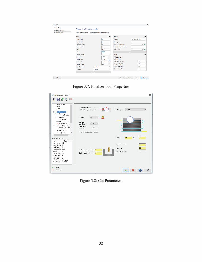
32
Figure 3.7: Finalize Tool Properties
Figure 3.8: Cut Parameters

33
Figure 3.9: Roughing
Figure 3.10: Linking Parameters
Figure 3.11: Entry Motion

34
Chapter 4- Data Collection and Analysis
This chapter aims at figuring out whether the CAD/CAM software simulated machining
time can reflect the practical machining time, what kind of influences the tool path make to
machining time and tool life, and how cutting tool affects machining process. Following shows
the results and date.
Software simulated result: Figure 4.1 presents the final machining result and some relevant
information like feed length, feed time, rapid length, rapid time, total length, and total machining
time.
Figure 4.1: Final simulated result
In addition, the software can also show the tool path of the machining process. Some tool
paths are shown below:

35
Figure 4.2a: Inside cut dynamic milling (tool 3)
Figure 4.2b: Inside cut dynamic milling (tool 5)

36
Figure 4.3: Inside cut area milling (tool 5)
Figure 4.4a: Inside cut pocket milling –zigzag rough (tool 5)

37
Figure 4.4b: Inside cut pocket milling-Constant overlap spiral rough (tool 5)
Figure 4.5: Outside area milling (tool 5)

38
Figure 4.6: Outside dynamic milling (tool 5)
4.1 Difference between Practical and Simulated Machining Time
To figure out the difference between practical machining time and simulated machining
time, 15 machining data are randomly selected. In the practical machining process, the maximum
spindle speed is 6000 rpm for the CNC machine. In order to protect the machine, the load in the
machining process should less than 100% most of the time. Therefore, the operator will decrease
the cutting speed and feed rate. The practical machining cutting speed and feed rate are different
from the one in CAD/CAM software. To compensate for the difference in practical operation, it
is necessary to adjust the cutting speed and feed rate in CAD/CAM software to match the
practical process. For this reason, all data from Mastercam can be used directly. Table 4.1 shows
the machining time, the simulation time and their difference.

39
Table 4.1: The difference between practical machining time and simulation time
experiment
objective
practical machining
time
simulated machining
time
difference(sec)
1 2m33s 1m41.41s 111.59
2 6m56s 6m3.2s 52.95
3 3m0s 2m5.6s 54.39
4 6m45s 5m28.17s 76.83
5 11m25s 9m43.28s 101.72
6 5m15s 4m5.36s 59.66
7 14m24s 12m19.05s 124.95
8 8m2s 6m10.4s 111.6
9 11m42s 11m28.63s 13.37
10 10m4s 9m12.73s 51.27
11 7m2s 6m51.86s 10.14
12 17m34s 16m7.39s 86.6
13 20m28s 20m23.88s 4.12
14 22m27s 20m0.93s 146.07
15 1m16s 51.98s 24.01
From the data given in table 4.1, most of the differences between practical machining time
and simulated machining time are over than 50 seconds. The Figure 4.7 shows the fluctuation of
the differences between practical machining time and simulated machining time. Therefore, the
simulated machining time does not reflect the practical machining time due to the difference
between them being unstable and vast.

40
Figure 4.7: The difference between practical machining time and simulation time
4.2 Tool Path Comparing
In order to understand what kind of influences the tool path make to machining time and
tool life, the research selects different tool paths to compare the results. In this section, all the
data are selected for tool 3 under the condition of spindle speed 3600 rpm, feed rate 18
inches/min. Table 4.2 shows the data about the practical machining time, practical feed time,
simulated machining time, feed length, rapid length, simulated feed time, and simulated rapid
time.

41
Table 4.2: The different tool path with the same cutting tool 3
tool path practical
machining
time
difference
time (s)
simulated
machining
time
feed
length
(inch)
rapid
length
(inch)
simulated
feed time
simulated
rapid time
outside
cutting
dynamic
milling
6m45s 76.83s 5m28.17s 146.98
6
8.319 5m27.17s 1s
outside
cutting
area
milling
11m25s 101.72s 9m43.28s 195.46
9
283.94
5
9m9.2s 34.07s
milling
7m2s 10.14s 6m51.86s 125.81
3
4.659 6m51.3s 0.56s
inside
cutting
dynamic
milling
11m42s 13.37s 11m28.63
s
236.96
7
6.227 11m27.88
s
0.75s
inside
cutting
area
milling
10m4s 51.27s 9m12.73s 185.54
7
5.209 9m12.1s 0.63s
42
From Table 4.2, the outside dynamic milling is the most efficient but the difference between
the practical machining time and the simulated machining time is huge, as compared to the
results obtained by other tool paths. Furthermore, feed length and rapid length in pocket milling
are shortest but its machining time is not the shortest. This is because, in order to reach to rough
cutting, pocket milling needs an entry motion in which the machining process needs to reduce
cutting speed and feed rate to prevent tool failure.
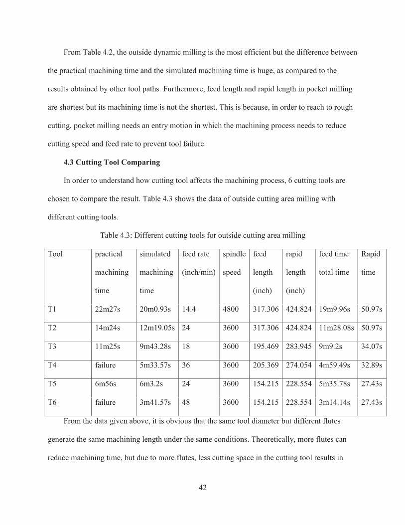
4.3 Cutting Tool Comparing
In order to understand how cutting tool affects the machining process, 6 cutting tools are
chosen to compare the result. Table 4.3 shows the data of outside cutting area milling with
different cutting tools.
Table 4.3: Different cutting tools for outside cutting area milling
Tool practical
machining
time
simulated
machining
time
feed rate
(inch/min)
spindle
speed
feed
length
(inch)
rapid
length
(inch)
feed time
total time
Rapid
time
T1 22m27s 20m0.93s 14.4 4800 317.306 424.824 19m9.96s 50.97s
T2 14m24s 12m19.05s 24 3600 317.306 424.824 11m28.08s 50.97s
T3 11m25s 9m43.28s 18 3600 195.469 283.945 9m9.2s 34.07s
T4 failure 5m33.57s 36 3600 205.369 274.054 4m59.49s 32.89s
T5 6m56s 6m3.2s 24 3600 154.215 228.554 5m35.78s 27.43s
T6 failure 3m41.57s 48 3600 154.215 228.554 3m14.14s 27.43s
From the data given above, it is obvious that the same tool diameter but different flutes
generate the same machining length under the same conditions. Theoretically, more flutes can
reduce machining time, but due to more flutes, less cutting space in the cutting tool results in

43
chips sticking on cutting tool and eventually leads to machining process failure, as shown in
Figure 4.8a. Sometimes inappropriate flutes will cause the cutting tool to break presented in
Figure 4.8b.
Figure 4.8a: Tool failure Figure 4.8b: Tool break
4.4 Failed Machining
In this experiment, some practical machining processes fail due to different reasons. The
result shows below in the following figures. The reason for the tool break in Figure 4.9a is that
the working tool abruptly changes its direction causing the tool break. Machining process failure
in Figure 4.9b and 4.9d are both due to chips sticking to the cutting tool. For Figure 4.9c, the
machining process generates too much heat, melting the workpiece.

44
Figure 4.9a Figure 4.9b
Figure 4.9c Figure 4.9d

45
Chapter 5- Conclusion and Future Research
This research mainly investigates the influences of the key parameters on the efficiency of
CNC machining. One main effort is to address the conflicting demand between extending the
tool life span and reducing the machining time. Through identifying the discrepancy between the
simulation time and the actual machine time under the same parametric setting, this research
gains insight to the applicability of a marketed CAD/CAM software in guiding the selection of
the practical CNC parameters for mass production. It is crucial to systematically test how the
parameters, such as the diameter, moving path, and flutes’ number of a cutting tool, affect
product quality in the real machining process.
The test reveals that the Mastercam software often cannot accurately predict the practical
CNC machining time because of the persistent difference between the software simulated
machining time and the practical CNC machining time. The time difference is varying from
4.12s to 146.07s.
Although the CAD/CAM software is unable to accurately calculate the machining time, it
can provide useful guidance on selecting tool path, diameter, and flutes. For example, the
CAD/CAM software can correctly predict that, for all the cutting tools that have been tested in
this research, the time discrepancy between the simulated machining time and the practical
machining time for the inside cutting method is smaller than the one for the outside cutting
method. The time difference is found to decrease in the order of outside area milling, outside
dynamic milling, inside cutting area milling, inside dynamic milling, and pocket milling.
This research reveals that a 4 flutes cutting tool is more prone to fail in a machining process
especially when the inside cutting method is used. The reason is that, as compared to a 2-flute
cutting tool, a 4-flute cutting tool has smaller flute valleys, which make chips difficult to escape

46
from the limited space, thereby causing temperature increase and chip sticking. The other reason
is related to the material being machined. Aluminum is soft. A cutting tool is much harder than it.
As a result, a cutting tool is fed fast, generating large chips. In the same time, aluminum is sticky,
and chips are hard to get out of the tool’s flutes.
In the practical machining process, machining load is changeable even under the same
cutting conditions. The changes of machining load happen when the cutting tool trajectory makes
a turn. The more degree changes, the more machining load increases. For this reason, the tool
path should avoid abrupt turns and thus prevent the generation of severe cutting forces.
Therefore, the tool path like zigzag should be avoided in the machining process. Compared to the
outside cutting method, the operator performing the inside cutting should pay attention to the
entry motion and chip clearance. Appropriate entry motion, such as helix interpolation and large
radius, can reduce cutting force and help grid of chips.
This experiment narrowly focuses on the limited cutting tools, workpiece materials, cutting
conditions, CNC milling, and the basic geometry. In order to fully fulfill the optimization of the
CAD/CAM system to improve CNC machining process, there are more factors needed to be
tested and analyzed.

47
References:
Akhtar, W., Sun, J.F., Sun, P.f., Chen, W.Y., & Saleem, Z. (2014). Tool wear mechanisms in the
machining of Nickel based super-alloys: A review. Frontiers of Mechanical Engineering. 9.
106-119. 10.1007/s11465-014-0301-2.
Diniz, A.E., Machado, Á.R. & Corrêa, J.G. (2016). Tool wear mechanisms in the machining of
steels and stainless steels. Int J Adv Manuf Technol 87: 3157.
https://doi.org/10.1007/s00170-016-8704-3
Dou, W. F., Song, X. D., & Zhang, X. Y. (2006). Design and Implementation of Synchronized
Collaborative System upon Heterogeneous CAD Systems, Journal of Algorithms &
Computational Technology Vol. 5 No. 3
Elmunafi, M. H. S., Yusof, N. M., & Kurniawan, D. (2015). Effect of cutting speed and feed in
turning hardened stainless steel using coated carbide cutting tool under minimum quantity
lubrication using castor oil. Advances in Mechanical Engineering, Vol. 7(8) 1–7. DOI:
10.1177/1687814015600666
Ferrell, E. R. (2017). Analysis of Tool Wear and Tool Life of Cutting Tool Inserts Using
Statistical Process Control Charts_ A Case Study. ProQuest Number:10274626
Gokulachandran, J., & Mohandas, K. (2015). Prediction of cutting tool life based on Taguchi
approach with fuzzy logic and support vector regression techniques. International Journal
of Quality & Reliability Management Vol. 32 No. 3, 2015 pp. 270-290
Ibrahim, K. (2005). CHARACTERISTIC OF CUTTING FORCES IN END MILLING. THE
UNIVERSITY OF NEW BRUNSWICK March. ISBN: 978-0-494-25334-2

48
Konobrytskyi, D. (2013). Automated CNC Tool Path Planning and Machining Simulation on
Highly Parallel Computing Architectures. ProQuest Number: 10159335
Park, K. H. (2012). TOOL WEAR ANALYSIS IN VARIOUS MACHINING PROCESSES AND
STUDY OF MINIMUM QUANTITY LUBRICATION (MQL). Published by ProQuest LLC.
Copyright in the Dissertation. UMI 3432302.
Smid, P. (2008). CNC Programming Handbook (3rd ed.), New York: Industrial Press, ISBN
9780831133474, LCCN 2007045901.
Sun, W., Chu, S., & Xiao, D. (2007). CAD/CAM/CNC of dies for car alloy wheels and golf clubs.
Proceedings of Advances in Computing and Technology, (AC&T) The School of
Computing and Technology 2nd Annual Conference, University of East London, pp.228-
232
Thakare, S. T. (2007). PROGRESS OF TOOL WEAR DURING MACHINING OF TITANIUM.
Published by Heritage Branch, ISBN: 978-0-494-49802-6
Wang, S, J. (2010). Modelling and Optimization of Cutting Strategy and Surface Generation in
Ultra-precision Raster Milling. Published by ProQuest LLC 2012. Copyright in the
Dissertation. UMI 3528709
Wu, Q. (2007). SERRATED CHIP FORMATION AND TOOL-EDGE WEAR IN HIGH-SPEED
MACHINING OF ADVANCED AEROSPACE MATERIALS. ProQuest LLC, UMI
Microform 3306449
Wang, X. (2012). A STUDY OF TOOL WEAR IN TURNING OF PURE ALUMINUM AND
DRILLING OF CFRP/TI STACKS, Published by ProQuest LLC (2012), UMI 3540429.

49
Wang, Y. C., Chen, C. H., & Lee, B. Y. (2014). Analysis model of parameters affecting cutting
performance in high-speed machining. Advanced Manufacturing Technol (2014) 72:521–
530, DOI 10.1007/s00170-013-5505-9