Embed Size (px)
Citation preview
United States Department of Agriculture / Forest Service
Rocky Mountain Research Station
Research Paper RMRS-RP-104
August 2013
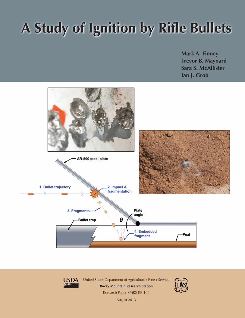
A Study of Ignition by Rifle Bullets
Mark A. Finney Trevor B. Maynard Sara S. McAllister Ian J. Grob
You may order additional copies of this publication by sending your mailing information in label form through one of the following media. Please specify the publication title and number.
Publishing Services Telephone (970) 498-1392
FAX (970) 498-1122
E-mail [email protected]
Web site http://www.fs.fed.us/rmrs
Mailing Address Publications Distribution Rocky Mountain Research Station 240 West Prospect Road Fort Collins, CO 80526
Finney, Mark A.; Maynard, Trevor B.; McAllister, Sara S.; Grob, Ian J. 2013. A study of ignition by rifle bullets. Res. Pap. RMRS-RP-104. Fort Collins, CO: U.S. Department of Agriculture, Forest Service, Rocky Mountain Research Station. 31 p.
Abstract
Experiments were conducted to examine the potential for rifle bullets to ignite organic matter after impacting a hard surface. The tests were performed using a variety of common cartridges (7.62x51, 7.62x39, 7.62x54R, and 5.56x45) and bullet materials (steel core, lead core, solid copper, steel jacket, and copper jacket). Bullets were fired at a steel plate that deflected fragments downward into a collection box containing oven-dried peat moss. We found that bullets could reliably cause ignitions, specifically those containing steel components (core or jacket) and those made of solid copper. Lead core-copper jacketed bullets caused one ignition in these tests. Ignitions of peat also occurred with a small set of tests using solid copper bullets and a granite target. Thermal infra-red video and temperature sensitive paints suggested that the temperature of bullet fragments could exceed 800°C. Bullet fragments collected from a water tank were larger for solid copper and steel core/jacketed bullets than for lead core bullets, which also facilitate ignition. Physical processes are reviewed with the conclusion that kinetic energy of bullets is transformed to thermal energy by plastic deformation and fracturing of bullets because of the high-strain rates during impact. Fragments cool rapidly but can ignite organic matter, particularly fine material, if very dry and close to the impact site.
Keywords: bullet fragmentation, fire ignition, shooting ignition
The Authors
Mark A. Finney: USDA Forest Service, Missoula Fire Sciences Laboratory, 5775 Highway 10 West, Missoula, MT 59808. [email protected], 406.329.4832
Trevor B. Maynard: USDA Forest Service, San Dimas Technology and Development Center, 444 E. Bonita Ave. San Dimas, CA 91773. [email protected], 909.599.1267 x258
Sara S. McAllister: USDA Forest Service, Missoula Fire Sciences Laboratory, 5775 Highway 10 West, Missoula, MT 59808. [email protected], 406.329.4907
Ian J. Grob: USDA Forest Service, Missoula Technology and Development Center, 5785 Highway 10 West, Missoula MT 59808. [email protected], 406.329.6775
Contents
Introduction .............................................................................................................. 1
Physical Processes ................................................................................................. 2Ignition of Organic Matter ............................................................................. 2Firearms and Energy Conversion ................................................................. 3
Heating Mechanisms ............................................................................................... 3Impact Mechanics ......................................................................................... 5Kinetic Energy—a Conceptual Model ........................................................... 5Stress/Strain-Based Models ......................................................................... 7Post-Impact Heat Losses ............................................................................. 7Heat Loss from Radiation ............................................................................. 8
Experimental Methods ............................................................................................ 9Fragment Temperatures ..............................................................................11Statistical Analysis ...................................................................................... 12Videography ............................................................................................... 12
Results.................................................................................................................... 13Bullet Material ............................................................................................. 14Temperatures of Bullet Fragments ............................................................. 21
Discussion ............................................................................................................. 22
Acknowledgments ................................................................................................. 25
References ............................................................................................................. 26
Appendix ................................................................................................................ 27

1USDA Forest Service Res. Pap. RMRS-RP-104. 2013
Introduction In the United States, outdoor target shooting has been suspected as the source of numerous wildland fires1,2. Anecdotally, the ammunition involved in most incidents is thought to be of ordinary commercial varieties with bullets composed of inert materials including lead, steel, and copper. No scientific studies have specifi-cally addressed projectile behavior or properties related to ignition of wildland vegetation or organic material. Thus, the primary focus of this study is whether inert projectiles fired from commonly available modern rifles can cause ignition of wildland vegetal matter. The possible mechanism by which inert projectiles could cause ignitions involves the conversion of kinetic energy to thermal energy at impact with a solid object or target. Kinetic energy is proportional to the product of an object’s mass and square of velocity, which is well known for the vast variety of cartridges available for modern firearms. In general, pistol cartridges are designed to propel a bullet much slower with less energy than rifle cartridges. Rifle bullets should thus be the most likely to have sufficient energy for ignition, provided some amount of that energy is converted to heat after impact. Table 1 indicates approximate muzzle energy for a variety of different cartridges. Ballistic impact has been researched extensively but has been directed principally toward understanding penetration or perforation of target materials. For a par-ticular target, projectiles of a given speed will perforate it at higher angles (closer to normal) and ricochet at lower angles (more oblique) (Johnson and others 1982,
1 Target shooting starts brush fire near Saratoga Springs. http://www.newsutah.org/utah/target-shooting-starts-brush-fire-14998/ 2 http://content.usatoday.com/communities/ondeadline/post/2012/07/gunfire-blamed-for-some-wildfires-states-consider-limits/1#.UCF4202PXwk
Goldsmith 1999). The consequences of such impacts most pertinent to ignition are where the impact:
1. Converts a large fraction of kinetic energy to ther-mal energy,
2. Fractures the bullet or target into pieces large enough to ignite organic matter, and
3. Ejects hot material into the organic matter.
We reasoned that these conditions should occur most commonly with oblique impacts on a highly resistant target (no penetration or perforation). This would pro-duce sufficient plastic deformation and friction of the projectile and direct the ricochet of particles into nearby organic wildland substrates. Plastic deformation is the irreversible change in shape of a material caused by an applied mechanical force. For most metals, upwards of 90% of the energy dissipated during rapid plastic de-formation is manifested as heat (Rogers 1979, Yildirim and others 2011), which is maintained within the bullet fragments for some period of time after impact. No empirical studies of bullet fragment temperatures have been found, but numerical experiments have shown temperature at the impact interface to increase with velocity (Molinari and Ortiz 2002, Yildirim and others 2011). At velocities comparable to rifle bullets (700-1000 m s-1) (Table 1), modeled temperatures of impact surfaces exceed 500 °C (Yildirim and others 2011, Molinari and Ortiz 2002). Additionally, laboratory studies of plastic deformation heating at less than bal-listic velocities have yielded temperature rises exceeding 350 °C (Hartley and others 1986). The ability of metal pieces to cause ignition was studied using heated steel spheres (Hadden and others 2011) and showed that hotter and larger spheres were more likely to cause ignitions in cellulose. The study of particles from arcing power lines (Tse and Fernandez-Pello 1998) suggests that smaller bullet fragments ejected from the impact site can fly farther but lose temperature more quickly than larger pieces.
Table 1. Typical velocity and kinetic energy of common small arms cartridges (U.S. Army 1994). Note: 1lb = 7000 grains.
Weight, g Muzzle velocity, Kinetic energy, J Cartridge Typical firearm used (grains) m s-1 (ft s-1) (ft-lb).22LR 22 rifle 3 (40) 361 (1185) 195 (144).45 ACP M1911 Semi-automatic pistol 15 (230) 270 (885) 547 (404)5.56 x 45mm NATO M-16 rifle 4 (62) 920 (3025) 1693 (1249)7.62 x 51mm NATO M-14 rifle 9 (146) 840 (2750) 3175 (2343).50 BMG M2 heavy machine gun 43 (660) 850 (2800) 15533 (11464)
2 USDA Forest Service Res. Pap. RMRS-RP-104. 2013
Physical Processes A series of physical processes are involved in trans-forming energy from the moving bullet into energy avail-able for ignition. For a material to be ignited, it must be heated to a temperature where oxidation reactions of the material release enough heat to independently continue the process. In the present situation, metal particles must be capable of contacting the fuel and conducting heat to it long enough to raise the temperature at contact points high enough for the oxidation reactions to self-sustain. The exact temperature at which this occurs is unknown and depends on the fuel, fuel bed characteristics, and environmental conditions. Because metal bullet frag-ments are small, more contact is likely with relatively fine grained material, which both increases likelihood of contact and decreases heat losses to adjoining mate-rial after contact. Water content changes the thermal properties of the fuel such that drier fuels require less heating to raise temperatures at the contact point to the critical level. The size and temperature of bullet fragments result-ing from impact depends very much on the mechanical properties of their constituent materials. The pertinent properties determine the response to rapid deformation and fracturing due to the high speed of bullets (~900 m s-1 or ~3000 ft s-1). Forces within the bullet at impact are responsible for compressing and shearing the metal into smaller pieces. Materials like steel or copper that require high energy to deform them (due to a greater “toughness”) are known to release this energy mostly as heat. Materials like lead are more easily deformed and melt at low temperatures and thus contain less heat and fracture in smaller pieces. The size of the pieces is important to both the distance they ricochet from the target and the rate at which they cool, mostly by contact with the cool air (convection). Tougher metals break into fewer and larger pieces and thus cool more slowly than smaller particles. Although the data available on fragment temperatures after impact are limited, rough calculations indicate that bullet energy should be capable of raising bullet tempera-tures above 1000 °C (1832 °F) under ideal conditions. The mechanical properties of metals vary considerably and will affect the actual temperature rise but are not well understood. Even so, the physical processes strongly demonstrate that ignition should be possible from rifle bullets and will vary by bullet material. A description of each of these physical processes as pertaining to bullet fragment ignition is discussed below.
Ignition of Organic Matter
Piloted ignition is the most common cause of wildland fires. Typical human-caused ignition sources include embers from campfires, arcing power lines, and hot debris from cutting and grinding (NWCG 2005). In each of these cases, the activity produces fragments of hot material that are capable of transferring enough heat to ignite surrounding vegetation. As mentioned in the introduction, in some cases, bullet impacts appear to generate high temperature fragments that could act as pilot ignition sources. To explore the mechanism by which a bullet impact may lead to ignition of nearby vegetation, we first dis-cuss the fundamentals of the ignition process. Ignition of wildland fuels can occur in two modes: flaming or smoldering. For thorough reviews of these modes of combustion, see Babrauskas (2003), Torero (2008), Ohlemiller (2008), and Rein (2009). Flaming ignition occurs when the fuel is exposed to a heat source that provides sufficient energy to cause thermal decomposi-tion of the material (pyrolysis). The gaseous pyrolysis products must escape the solid and mix with the air (oxidizer). This mixture can either be ignited with an external localized energy source (piloted ignition) or ignited via self-heating (autoignition). To achieve sus-tained flaming ignition (and hence establish a diffusion flame), the rate of decomposition (pyrolysis) must be sufficiently large so that the heat release rate from this premixed fuel-air flame is larger than the heat loss rate. In contrast to flaming ignition, which occurs in the gas phase, smoldering ignition occurs in the solid phase and no visible flame is seen. Smoldering is also initiated by heating the solid to a temperature high enough for thermal degradation (pyrolysis) to occur, resulting in formation of a char. The required heating rate is typically much slower than for flaming ignition. If available, oxygen will react directly on the surface of the solid char left by the pyrolysis reaction. This oxidation reaction is exothermic, generating all the heat from smoldering combustion, and is the heat source for further propagation of smoldering combustion. Smoldering combustion is thus a much slower form of combustion with considerably lower temperatures than flaming combustion (approximately 600 °C versus 1200 °C). However, the heating required to initiate smoldering combustion is considerably lower than flaming combustion. Additionally, smoldering can transition to flaming combustion when conditions change, such as more air (oxidizer) becoming available when the wind speed increases, creating a “hazardous shortcut to flaming fires” (Rein 2009). In forest fuels,
3USDA Forest Service Res. Pap. RMRS-RP-104. 2013
this transition from smoldering to flaming can take days, even weeks, such as in lightning ignited fires (Wotton and Martell 2005, Pineda and others 2012). Smoldering ignition is thus as much of a concern as direct flaming ignition. This study is focused on the likelihood of ignition of wildland fires via contact with hot bullet fragments. Unfortunately, ignition by contact with hot particles is not well understood (Babrauskas 2003, ch. 7, 11, and 14). There are relatively few well-controlled experimental studies examining this mode of ignition and even fewer practical theoretical models. According to Babrauskas (2003), existing theoretical models fall short for four main reasons: no experimental validation, most practical situations violate the basic assumptions of the model, the problem is probabilistic and no models include probability, and the material properties of the solid to be ignited are largely unknown (page 500). Based on what little research has been done in this area, however, a few general trends have been noted. In general, the hot particle must be at a substantially higher temperature than the ignition temperature measured under radiant or convective heating (Setchkin 1949, Kuchta and others 1969, Tanaka 1977). Additionally, higher temperatures are required to initiate both smoldering and flaming ignition as the particle size decreases (Hadden and oth-ers 2011, Rowntree 1994, Stokes 1990, Gol’dshleger and others 1973, Tanaka 1977). By performing experiments with steel and aluminum ball bearings in conjunction with a theoretical model, Gol’dshleger and others (1973) showed that increasing the conductivity of the hot particle lowered the required particle temperature. Studies with firebrands indicate that a higher flux of particles will increase the probability of ignition (Manzello and others 2006a, 2006b, 2008). Increasing the moisture content of both sawdust and pine needle beds has been shown to increase the required particle temperature (Tanaka 1977) and thus decrease the ignition probability (Ellis 2000). The density or physical structure of the recep-tive fuel was also shown to influence the probability of ignition, with fluffy cotton much easier to ignite than tightly woven cotton (McGuire and others 1956). As a worse-case scenario, dry fluffy commercially available peat moss was chosen in this study as the receptive material. The density, moisture content, and mineral (or ash) content of peat has been shown to affect its ignitability. In general, it is more difficult to ignite peat when the density or moisture content increases (Hartford 1989, Grishin and others 2006). However, the minimum ignition energy of Russian peat was shown by Grishin and others (2006) to have an optimum level of
both density and moisture content. For the lowest den-sity tested (0.38x10³ kg m-3), an increase in the ignition energy was seen. A similar increase in ignition energy was seen with extremely low values of moisture content (<1% MC). The combined effect of mineral content and moisture content was examined by Frandsen (1987, 1997) where it was shown that as the mineral content increases the maximum moisture content for ignition decreases.
Firearms and Energy Conversion
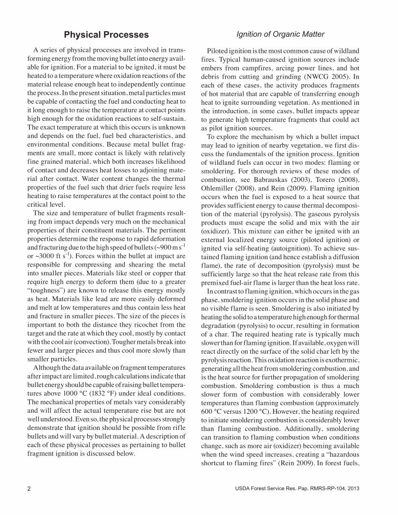
In physics, energy is a measure of the ability to per-form mechanical work. For a firearm, the mechanical work being performed is the acceleration of a projectile to a desired velocity. Though energy can exist in many forms, the most relevant for firearms are potential, kinetic, and thermal energy. Potential energy is stored energy that could be converted to work. Examples of potential energy include a compressed spring (elastic potential energy) and propellant stored inside of an am-munition cartridge (chemical potential energy). Kinetic energy is the energy possessed by an object due to its motion. Thermal energy is associated with an object’s temperature. The discharge of a firearm involves the exchange of significant amounts of energy (Figure 1). Prior to fir-ing, potential energy is stored in the form of propellant inside of the cartridge. Once the trigger is pulled and the firing pin strikes the primer on the cartridge, the propellant ignites and burns rapidly. This generates hot, expanding gases that propel the bullet down the barrel, giving it kinetic energy. Typical values of kinetic energy for common cartridges are shown in Table 1.
Heating Mechanisms During firearm discharge, bullets are exposed to several sources of heating. Inside the barrel, heat is transferred to the bullet by the propellant gases and by friction with the barrel itself. The bullet is also heated by friction with air as it travels toward the target at supersonic speed. However, in both cases, the duration is extremely short, so their contribution to temperature increase is likely minimal. If in-barrel and aerodynamic heating are negligible in terms of bullet temperature increase, the only remaining source of heating is interaction between the bullet and target. As the bullet impacts its target, some or all of its kinetic energy is converted into other forms. Some is converted to observable mechanical work, such as
4 USDA Forest Service Res. Pap. RMRS-RP-104. 2013
deformation and perforation of the target and distor-tion of the bullet. Part of the kinetic energy is also dissipated into forms that cannot be easily observed, such as thermal energy (temperature) in the projectile and target, and pressure waves. Depending on target/projectile construction and impact angle, the bullet may retain some of its kinetic energy (and thus its motion) after impact. The mechanics of energy dissipation depend on target and bullet construction. A paper target requires a mini-mal amount of energy to perforate; a bullet penetrating it will transfer a small amount of its kinetic energy and will continue traveling at a slightly reduced velocity. However, a more resilient target, such as a steel plate,
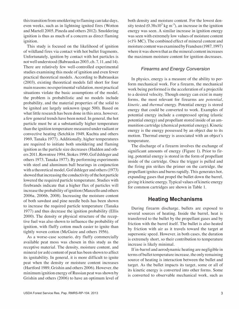
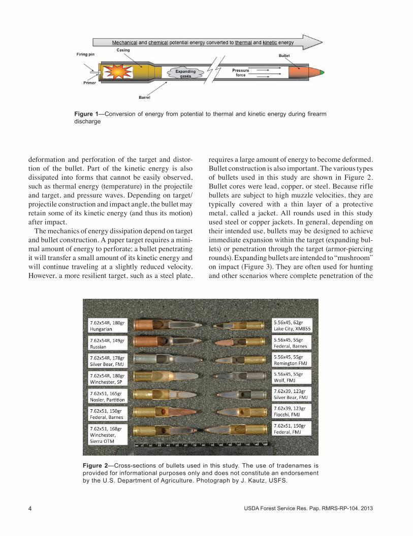
requires a large amount of energy to become deformed. Bullet construction is also important. The various types of bullets used in this study are shown in Figure 2. Bullet cores were lead, copper, or steel. Because rifle bullets are subject to high muzzle velocities, they are typically covered with a thin layer of a protective metal, called a jacket. All rounds used in this study used steel or copper jackets. In general, depending on their intended use, bullets may be designed to achieve immediate expansion within the target (expanding bul-lets) or penetration through the target (armor-piercing rounds). Expanding bullets are intended to “mushroom” on impact (Figure 3). They are often used for hunting and other scenarios where complete penetration of the
Figure 1—Conversion of energy from potential to thermal and kinetic energy during firearm discharge
Figure 2—Cross-sections of bullets used in this study. The use of tradenames is provided for informational purposes only and does not constitute an endorsement by the U.S. Department of Agriculture. Photograph by J. Kautz, USFS.
5USDA Forest Service Res. Pap. RMRS-RP-104. 2013
target is undesirable. Armor-piercing rounds typically contain a penetrator constructed of steel or another high density metal. The jacket is destroyed on impact, but the penetrator’s momentum propels it into the target substrate.
Impact Mechanics
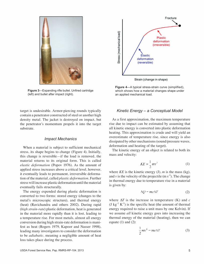
When a material is subject to sufficient mechanical stress, its shape begins to change (Figure 4). Initially, this change is reversible—if the load is removed, the material returns to its original form. This is called elastic deformation (Popov 1976). As the amount of applied stress increases above a critical level, however, it eventually leads to permanent, irreversible deforma-tion of the material, called plastic deformation. Further stress will increase plastic deformation until the material eventually fails structurally. The energy expended during plastic deformation is converted to two forms: stored energy (changes to the metal’s microscopic structure), and thermal energy (heat) (Ravichandra and others 2002). During rapid (high strain-rate) plastic deformation, heat is generated in the material more rapidly than it is lost, leading to a temperature rise. For most metals, almost all energy conversion during high strain-rate deformation is mani-fest as heat (Rogers 1979, Kapoor and Nasser 1998), leading many investigators to consider the deformation to be adiabatic, meaning a negligible amount of heat loss takes place during the process.
Kinetic Energy – a Conceptual Model
As a first approximation, the maximum temperature rise due to impact can be estimated by assuming that all kinetic energy is converted into plastic deformation heating. This approximation is crude and will yield an overestimate of temperature rise, since energy is also dissipated by other mechanisms (sound/pressure waves, deformation and heating of the target). The kinetic energy of an object is related to both its mass and velocity:
(1)
where KE is the kinetic energy (J), m is the mass (kg), and v is the velocity of the projectile (m s-1). The change in thermal energy due to temperature rise in a material is given by:
(2)
where ∆T is the increase in temperature (K) and c (J kg-1 K-1) is the specific heat (the amount of thermal energy required to raise a unit mass by one Kelvin). If we assume all kinetic energy goes into increasing the thermal energy of the material (heating), then we can equate (1) and (2):
(3)
Figure 3—Expanding rifle bullet. Unfired cartridge (left) and bullet after impact (right).
Figure 4—A typical stress-strain curve (simplified), which shows how a material changes shape under an applied mechanical load.
6 USDA Forest Service Res. Pap. RMRS-RP-104. 2013
Since mass appears on both sides of (3), it can be eliminated, leaving us with a simplified estimate of temperature rise:
(4)
Of significance in Eq. 4 is the lack of dependence of temperature rise on mass. For this idealized impact of a bullet of given material at a specified velocity, the temperature increase of the projectile is independent of its size and shape. In our experiments, all bullets deformed to the point of fracture, resulting in individual fragments rather than a single mass. All the heating was due to plastic deformation that occurred prior to fragmentation. Assuming the bullet was a uniform tem-perature throughout just prior to fragmentation, all the fragments should be the same temperature and equal to the temperature of the whole.
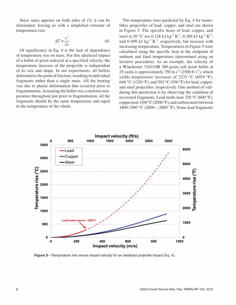
The temperature rises predicted by Eq. 4 for mono-lithic projectiles of lead, copper, and steel are shown in Figure 5. The specific heats of lead, copper, and steel at 20 °C are 0.128 kJ kg-1 K-1, 0.386 kJ kg-1 K-1, and 0.490 kJ kg-1 K-1, respectively, but increase with increasing temperature. Temperatures in Figure 5 were calculated using the specific heat at the midpoint of ambient and final temperature (determined using an iterative procedure). As an example, the velocity of a Winchester 7.62x54R 180-grain soft point bullet at 25 yards is approximately 750 m s-1 (2500 ft s-1), which yields temperature increases of 2233 °C (4019 °F), 660 °C (1220 °F), and 502 °C (936 °F) for lead, copper, and steel projectiles, respectively. One method of vali-dating this prediction is by observing the condition of recovered fragments. Lead melts near 320 °C (600 °F), copper near 1100 °C (2000 °F), and carbon steels between 1400-1500 °C (2600 – 2800 °F). Some lead fragments
Figure 5—Temperature rise versus impact velocity for an idealized projectile impact (Eq. 4).
7USDA Forest Service Res. Pap. RMRS-RP-104. 2013
recovered during our experiments appeared to have melted and re-solidified, but this was not evident for any copper or steel fragments. This observation, though rudimentary, is in agreement with the calculated values.
Stress/Strain-Based Models
The simple model described above does not account for the mechanical properties of materials subject to impact loading. The amount of heating caused by plastic deformation depends on strain rate, the type of loading, and the material itself. When a bullet strikes a target, it deforms plastically. With sufficient impact velocity and target rigidity, the bullet may fail structurally with only minimal penetration into the target. Xiao and others (2010) identified four distinct deformation and failure modes for blunt-shaped steel (38CrSi) projectiles fired at rigid steel plates. The first mechanism, mushrooming, occurred at relatively low velocities (150-250 m s-1 [500-800 ft s-1]) and was characterized by the radial expansion at the nose of the projectile, leading to a mushroom-shaped appearance, but not causing fracture. As impact velocity increased, the second failure mode, shear cracking, became evident. The mushrooming effect causes stresses to be localized in the head of the projectile, which can lead to cracks that begin at the impact face and propagate backwards. Of significance in Xiao and others’ (2010) experiments was the bluish discoloration (oxidation) at the head and cracked interface of the projectile, indicating sig-nificant heating. For plain carbon steels, this occurs at 255-320 °C (500-600 °F) (Oberg and others 1990). After shear cracking, the failure modes observed by Xiao and others (2010) were dependent on mate-rial hardness. Softer projectiles experienced petalling. Petalling is an extension of shear cracking but occurs at higher velocity. The shear cracks propagate even farther rearward, giving the projectile a petalled ap-pearance, similar to the expanded bullet shown in Figure 3. Significant discoloration of the petals was evident over much of their length, indicating sustained high temperatures during deformation. Hard projectiles experienced fragmentation—the projectiles shattered into many pieces. The number of fragments increased with projectile velocity. Fragments had some surface discoloration, but it was less prevalent than with the softer petalled projectiles.
Currently, there is no accepted theoretical model that completely describes the heating of objects as they undergo plastic deformation. However, Quinney and Taylor (1937) proposed the use of an energy balance model to estimate the material temperature rise as a function of strain:
(5)
where η is the fraction of plastic deformation work converted to heat, and ∆W is the mechanical work done. Since the area under the true stress-strain curve represents the plastic work done per unit volume (for deformation in a single axis), the temperature rise can be estimated as a function of strain:
(6)
(7)
where ε is the true strain, σ is the true stress (N m-1), and cv is the specific heat of the material at constant volume (J kg-1 K-1). Though dynamic stress-strain data are limited for high strain rate experiments (due to the difficulty of measurement), we can make some qualitative arguments about the effect of different ma-terials. Brittle materials have limited ductility and do not undergo much plastic deformation before fracturing, while very ductile materials (like copper) can experi-ence significant plastic deformation (Rittel and Osovski 2010). In general, the area under the stress/strain curve (the integral in Eq. 7) will increase with ductility (as-suming the strength remains comparable), which predicts a greater temperature rise for more ductile materials.
Post-Impact Heat Losses
After impact, fragments are reflected from the target surface and travel some distance before reaching the ground. During flight, fragments will lose heat through convective and radiative heat transfer to the surroundings. Though their time of flight was not measured, visible observations indicated that fragments in our experiments were airborne for only a fraction of a second before landing on the surface. To estimate the effect of heat loss during this time, consider the deflection of a bullet
8 USDA Forest Service Res. Pap. RMRS-RP-104. 2013
fragment created during impact. As the fragment falls toward the ground, its surface is exposed to an external airflow that aids in removing heat from the material—this is called forced convection. Because the fragments are small (“thermally thin”), this situation is amenable to a special type of heat transfer analysis called lumped capacitance (Incropera and DeWitt 2007). Using lumped capacitance analysis, the time required for an object to experience a specified change in tem-perature is given as:
(8)
where ρ is the density of the material (kg m-3), V is the volume of the object (m3), h is the convective heat transfer coefficient (W m-2 K-1), AS is the surface area (m2), and subscripts i, f, and ∞ represent the initial, fi-nal, and ambient temperatures, respectively. In forced convection, the convection coefficient is determined from the Nusselt number, which represents the ratio of convection to conduction heat transfer:
(9)
where k is the thermal conductivity of the surrounding fluid (air) (W m-1 K-1) and L represents the length scale of the object (m). For circular cylinders in cross flow, Churchill and Bernstein (1977) provide a correlation for the Nusselt number over a wide range of flow conditions:
(10)
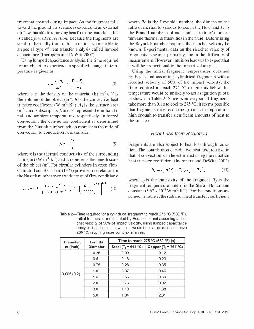
where Re is the Reynolds number, the dimensionless ratio of inertial to viscous forces in the flow, and Pr is the Prandtl number, a dimensionless ratio of momen-tum and thermal diffusivities in the fluid. Determining the Reynolds number requires the ricochet velocity be known. Experimental data on the ricochet velocity of fragments is scarce, primarily due to the difficulty of measurement. However, intuition leads us to expect that it will be proportional to the impact velocity. Using the initial fragment temperatures obtained by Eq. 4, and assuming cylindrical fragments with a ricochet velocity of 50% of the impact velocity, the time required to reach 275 °C (fragments below this temperature would be unlikely to act as ignition pilots) is shown in Table 2. Since even very small fragments take more than 0.1 s to cool to 275 °C, it seems possible that fragments may reach the ground at temperatures high enough to transfer significant amounts of heat to the surface.
Heat Loss from Radiation
Fragments are also subject to heat loss through radia-tion. The contribution of radiative heat loss, relative to that of convection, can be estimated using the radiation heat transfer coefficient (Incropera and DeWitt, 2007)
(11)
where εf is the emissivity of the fragment, Tf is the fragment temperature, and σ is the Stefan-Boltzmann constant (5.67 x 10⁻⁸ W m-2 K-4). For the conditions as-sumed in Table 2, the radiation heat transfer coefficients
Table 2—Time required for a cylindrical fragment to reach 275 °C (530 °F). Initial temperature estimated by Equation 4 and assuming a rico-chet velocity of 50% of impact velocity, using lumped capacitance analysis. Lead is not shown, as it would be in a liquid phase above 230 °C, requiring more complex analysis.
Diameter, m (inch)
Length/Diameter
Time to reach 275 °C (530 °F) (s)Steel (Ti = 614 °C) Copper (Ti = 767 °C)
0.005 (0.2)
0.25 0.09 0.120.5 0.18 0.230.75 0.28 0.351.0 0.37 0.461.5 0.55 0.692.0 0.73 0.923.0 1.10 1.385.0 1.84 2.31
9USDA Forest Service Res. Pap. RMRS-RP-104. 2013
for both steel and copper are nearly two orders magnitude less than their convection coefficients, which implies the contribution from radiative heat loss is negligible.
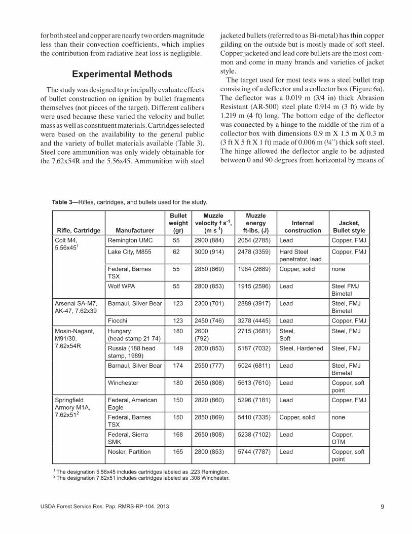
Experimental Methods The study was designed to principally evaluate effects of bullet construction on ignition by bullet fragments themselves (not pieces of the target). Different calibers were used because these varied the velocity and bullet mass as well as constituent materials. Cartridges selected were based on the availability to the general public and the variety of bullet materials available (Table 3). Steel core ammunition was only widely obtainable for the 7.62x54R and the 5.56x45. Ammunition with steel
jacketed bullets (referred to as Bi-metal) has thin copper gilding on the outside but is mostly made of soft steel. Copper jacketed and lead core bullets are the most com-mon and come in many brands and varieties of jacket style. The target used for most tests was a steel bullet trap consisting of a deflector and a collector box (Figure 6a). The deflector was a 0.019 m (3/4 in) thick Abrasion Resistant (AR-500) steel plate 0.914 m (3 ft) wide by 1.219 m (4 ft) long. The bottom edge of the deflector was connected by a hinge to the middle of the rim of a collector box with dimensions 0.9 m X 1.5 m X 0.3 m (3 ft X 5 ft X 1 ft) made of 0.006 m (¼”) thick soft steel. The hinge allowed the deflector angle to be adjusted between 0 and 90 degrees from horizontal by means of
Table 3—Rifles, cartridges, and bullets used for the study.
Rifle, Cartridge Manufacturer
Bullet weight
(gr)
Muzzle velocity f s-1,
(m s-1)
Muzzle energy
ft-lbs, (J)Internal
constructionJacket,
Bullet styleColt M4, 5.56x451
Remington UMC 55 2900 (884) 2054 (2785) Lead Copper, FMJ
Lake City, M855 62 3000 (914) 2478 (3359) Hard Steel penetrator, lead
Copper, FMJ
Federal, Barnes TSX
55 2850 (869) 1984 (2689) Copper, solid none
Wolf WPA 55 2800 (853) 1915 (2596) Lead Steel FMJ Bimetal
Arsenal SA-M7, AK-47, 7.62x39
Barnaul, Silver Bear 123 2300 (701) 2889 (3917) Lead Steel, FMJBimetal
Fiocchi 123 2450 (746) 3278 (4445) Lead Copper, FMJ
Mosin-Nagant, M91/30, 7.62x54R
Hungary(head stamp 21 74)
180 2600(792)
2715 (3681) Steel, Soft
Steel, FMJ
Russia (188 head stamp, 1989)
149 2800 (853) 5187 (7032) Steel, Hardened Steel, FMJ
Barnaul, Silver Bear 174 2550 (777) 5024 (6811) Lead Steel, FMJ Bimetal
Winchester 180 2650 (808) 5613 (7610) Lead Copper, soft point
Springfield Armory M1A, 7.62x512
Federal, American Eagle
150 2820 (860) 5296 (7181) Lead Copper, FMJ
Federal, Barnes TSX
150 2850 (869) 5410 (7335) Copper, solid none
Federal, Sierra SMK
168 2650 (808) 5238 (7102) Lead Copper, OTM
Nosler, Partition 165 2800 (853) 5744 (7787) Lead Copper, soft point
1 The designation 5.56x45 includes cartridges labeled as .223 Remington. 2 The designation 7.62x51 includes cartridges labeled as .308 Winchester.
10 USDA Forest Service Res. Pap. RMRS-RP-104. 2013
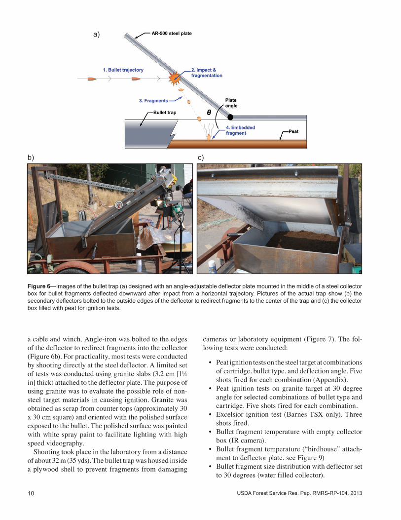
Figure 6—Images of the bullet trap (a) designed with an angle-adjustable deflector plate mounted in the middle of a steel collector box for bullet fragments deflected downward after impact from a horizontal trajectory. Pictures of the actual trap show (b) the secondary deflectors bolted to the outside edges of the deflector to redirect fragments to the center of the trap and (c) the collector box filled with peat for ignition tests.
a)
b) c)
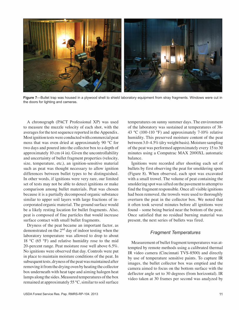
a cable and winch. Angle-iron was bolted to the edges of the deflector to redirect fragments into the collector (Figure 6b). For practicality, most tests were conducted by shooting directly at the steel deflector. A limited set of tests was conducted using granite slabs (3.2 cm [1¼ in] thick) attached to the deflector plate. The purpose of using granite was to evaluate the possible role of non-steel target materials in causing ignition. Granite was obtained as scrap from counter tops (approximately 30 x 30 cm square) and oriented with the polished surface exposed to the bullet. The polished surface was painted with white spray paint to facilitate lighting with high speed videography. Shooting took place in the laboratory from a distance of about 32 m (35 yds). The bullet trap was housed inside a plywood shell to prevent fragments from damaging
cameras or laboratory equipment (Figure 7). The fol-lowing tests were conducted:
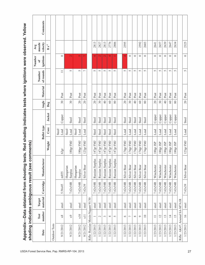
• Peat ignition tests on the steel target at combinations of cartridge, bullet type, and deflection angle. Five shots fired for each combination (Appendix).
• Peat ignition tests on granite target at 30 degree angle for selected combinations of bullet type and cartridge. Five shots fired for each combination.
• Excelsior ignition test (Barnes TSX only). Three shots fired.
• Bullet fragment temperature with empty collector box (IR camera).
• Bullet fragment temperature (“birdhouse” attach-ment to deflector plate, see Figure 9)
• Bullet fragment size distribution with deflector set to 30 degrees (water filled collector).
11USDA Forest Service Res. Pap. RMRS-RP-104. 2013
A chronograph (PACT Professional XP) was used to measure the muzzle velocity of each shot, with the averages for the test sequence reported in the Appendix. Most ignition tests were conducted with commercial peat moss that was oven dried at approximately 90 °C for two days and poured into the collector box to a depth of approximately 10 cm (4 in). Given the uncontrollability and uncertainty of bullet fragment properties (velocity, size, temperature, etc.), an ignition-sensitive material such as peat was thought necessary to allow ignition differences between bullet types to be distinguished. In other words, if ignitions were very rare, our limited set of tests may not be able to detect ignitions or make comparison among bullet materials. Peat was chosen because it is a partially decomposed organic substance similar to upper soil layers with large fractions of in-corporated organic material. The ground surface would be a likely resting location for bullet fragments. Also, peat is composed of fine particles that would increase surface contact with small bullet fragments. Dryness of the peat became an important factor, as demonstrated on the 2nd day of indoor testing when the laboratory temperature was allowed to drop to about 18 °C (65 °F) and relative humidity rose to the mid 20-percent range. Peat moisture rose well above 6.5%. No ignitions were observed that day. Controls were put in place to maintain moisture conditions of the peat. In subsequent tests, dryness of the peat was maintained after removing it from the drying oven by heating the collector box underneath with heat tape and aiming halogen heat lamps along the sides. Measured temperatures of the box remained at approximately 55 °C, similar to soil surface
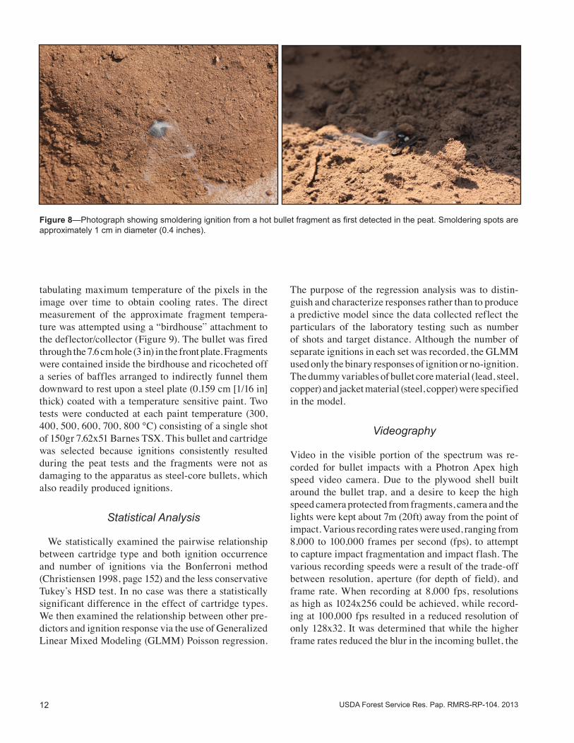
temperatures on sunny summer days. The environment of the laboratory was sustained at temperatures of 38-43 °C (100-110 °F) and approximately 7-10% relative humidity. This preserved moisture content of the peat between 3.0-4.5% (dry weight basis). Moisture sampling of the peat was performed approximately every 15 to 30 minutes using a Computrac MAX 2000XL automatic balance. Ignitions were recorded after shooting each set of bullets by first observing the peat for smoldering spots (Figure 8). When observed, each spot was excavated with a small trowel. The volume of peat containing the smoldering spot was sifted on the pavement to attempt to find the fragment responsible. Once all visible ignitions had been removed, the trowels were used to thoroughly overturn the peat in the collector box. We noted that it often took several minutes before all ignitions were found – some being buried near the bottom of the peat. Once satisfied that no residual burning material was present, the next series of bullets was fired.
Fragment Temperatures
Measurement of bullet fragment temperatures was at-tempted by remote methods using a calibrated thermal IR video camera (Cincinnati TVS-8500) and directly by use of temperature sensitive paints. To capture IR images, the bullet collector box was emptied and the camera aimed to focus on the bottom surface with the deflector angle set to 30 degrees (from horizontal). IR video taken at 30 frames per second was analyzed by
Figure 7—Bullet trap was housed in a plywood shell to shield laboratory equipment from stray fragments. Windows were cut in the doors for lighting and cameras.
12 USDA Forest Service Res. Pap. RMRS-RP-104. 2013
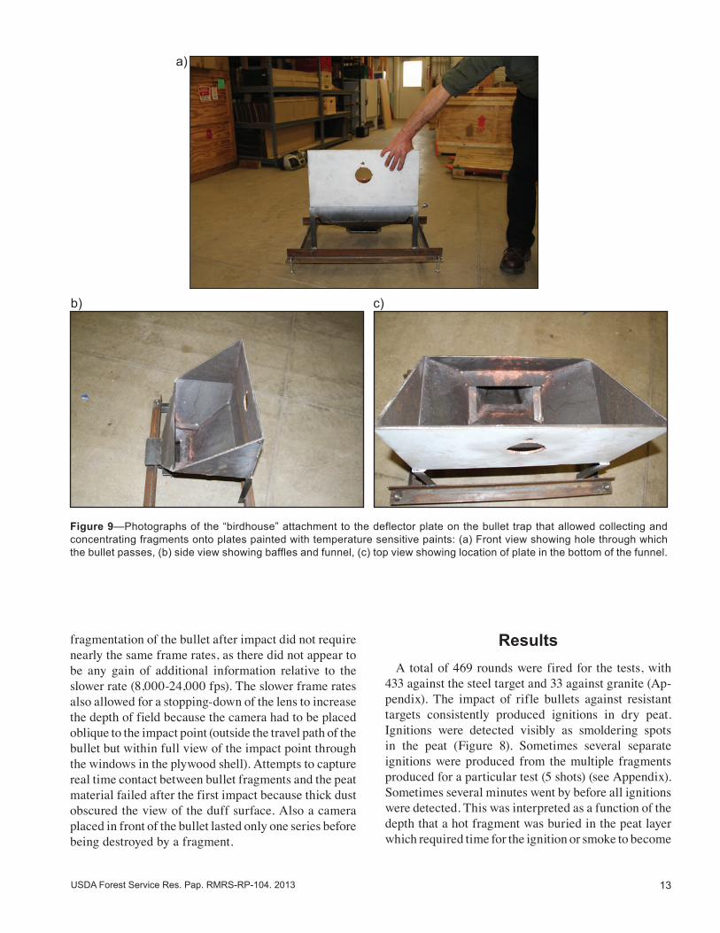
tabulating maximum temperature of the pixels in the image over time to obtain cooling rates. The direct measurement of the approximate fragment tempera-ture was attempted using a “birdhouse” attachment to the deflector/collector (Figure 9). The bullet was fired through the 7.6 cm hole (3 in) in the front plate. Fragments were contained inside the birdhouse and ricocheted off a series of baffles arranged to indirectly funnel them downward to rest upon a steel plate (0.159 cm [1/16 in] thick) coated with a temperature sensitive paint. Two tests were conducted at each paint temperature (300, 400, 500, 600, 700, 800 °C) consisting of a single shot of 150gr 7.62x51 Barnes TSX. This bullet and cartridge was selected because ignitions consistently resulted during the peat tests and the fragments were not as damaging to the apparatus as steel-core bullets, which also readily produced ignitions.
Statistical Analysis
We statistically examined the pairwise relationship between cartridge type and both ignition occurrence and number of ignitions via the Bonferroni method (Christiensen 1998, page 152) and the less conservative Tukey’s HSD test. In no case was there a statistically significant difference in the effect of cartridge types. We then examined the relationship between other pre-dictors and ignition response via the use of Generalized Linear Mixed Modeling (GLMM) Poisson regression.
The purpose of the regression analysis was to distin-guish and characterize responses rather than to produce a predictive model since the data collected reflect the particulars of the laboratory testing such as number of shots and target distance. Although the number of separate ignitions in each set was recorded, the GLMM used only the binary responses of ignition or no-ignition. The dummy variables of bullet core material (lead, steel, copper) and jacket material (steel, copper) were specified in the model.
Videography
Video in the visible portion of the spectrum was re-corded for bullet impacts with a Photron Apex high speed video camera. Due to the plywood shell built around the bullet trap, and a desire to keep the high speed camera protected from fragments, camera and the lights were kept about 7m (20ft) away from the point of impact. Various recording rates were used, ranging from 8,000 to 100,000 frames per second (fps), to attempt to capture impact fragmentation and impact flash. The various recording speeds were a result of the trade-off between resolution, aperture (for depth of field), and frame rate. When recording at 8,000 fps, resolutions as high as 1024x256 could be achieved, while record-ing at 100,000 fps resulted in a reduced resolution of only 128x32. It was determined that while the higher frame rates reduced the blur in the incoming bullet, the
Figure 8—Photograph showing smoldering ignition from a hot bullet fragment as first detected in the peat. Smoldering spots are approximately 1 cm in diameter (0.4 inches).
13USDA Forest Service Res. Pap. RMRS-RP-104. 2013
fragmentation of the bullet after impact did not require nearly the same frame rates, as there did not appear to be any gain of additional information relative to the slower rate (8,000-24,000 fps). The slower frame rates also allowed for a stopping-down of the lens to increase the depth of field because the camera had to be placed oblique to the impact point (outside the travel path of the bullet but within full view of the impact point through the windows in the plywood shell). Attempts to capture real time contact between bullet fragments and the peat material failed after the first impact because thick dust obscured the view of the duff surface. Also a camera placed in front of the bullet lasted only one series before being destroyed by a fragment.
Results A total of 469 rounds were fired for the tests, with 433 against the steel target and 33 against granite (Ap-pendix). The impact of rifle bullets against resistant targets consistently produced ignitions in dry peat. Ignitions were detected visibly as smoldering spots in the peat (Figure 8). Sometimes several separate ignitions were produced from the multiple fragments produced for a particular test (5 shots) (see Appendix). Sometimes several minutes went by before all ignitions were detected. This was interpreted as a function of the depth that a hot fragment was buried in the peat layer which required time for the ignition or smoke to become
Figure 9—Photographs of the “birdhouse” attachment to the deflector plate on the bullet trap that allowed collecting and concentrating fragments onto plates painted with temperature sensitive paints: (a) Front view showing hole through which the bullet passes, (b) side view showing baffles and funnel, (c) top view showing location of plate in the bottom of the funnel.
a)
b) c)
14 USDA Forest Service Res. Pap. RMRS-RP-104. 2013
visible on the surface. A single test for ignition of dry excelsior by the solid copper bullets (3 bullets) against the steel target produced ignitions. The tests using a granite target were inconclusive because of problems encountered with breakage by larger bullets and affix-ing the granite slabs tightly against the deflector for more than one shot. However, solid copper bullets did produce ignitions following impact with granite. Fragments found by excavating ignitions in the peat suggested that bullet fragments were responsible for the ignition rather than steel eroded from the target. For steel jacketed bullets, very small fragments of jacket mate-rial were often found inside the incipient ignition. At low target angles, little cratering of the target occurred regardless of bullet type and limiting alternative sources of hot materials other than bullet fragments themselves. At high target angles using bullets with hardened steel penetrators, cratering of the steel target (Figure 10) could have liberated steel fragments and contributed to the ignitions. The process of deformation and fragmentation of the target would produce hot particles in the same way as discussed for bullet fragments. We did observe in one place where the sharp edge of a crater rim on the target had chipped from subsequent impacts and could have contributed hot material for ignition.
Figure 10—Cratering of AR-500 steel plate by steel core bullets was visible at high impact angle (60-80 degrees from horizontal) but not at low angles (20-40 degrees from horizontal).
Statistical analysis of the ignition results by Poisson regression revealed significant differences among bullet materials (Figure 11). The regression model (Table 4) represented separately the effects of core material and the jacket material compared to the base model that represented solid copper bullets (zeros for variables STEELCORE and LEADCORE and STEELJACKET).
Bullet Material
Bullet construction materials were important factors in producing ignition (Table 1) (Figure 2). The only type of bullet that consistently did not produce ignitions was made with a lead core and copper jacket, although a single ignition was observed from a Nosler partition bullet. Two other ignitions resulting from lead core and copper jacketed bullets occurred immediately after shots involving solid copper bullets and were probably undetected hold-over ignitions from that test given their location in the collector that coincided with large areas of smoldering peat (Appendix). Solid copper bullets were the most consistent in producing ignitions at all angles and all targets. Fragments of the solid copper bullets appeared larger than fragments of other bullet types. Fragments recovered from the water-filled collector box
15USDA Forest Service Res. Pap. RMRS-RP-104. 2013
Figure 11—Graph showing statistical regression model of laboratory data on probability of ignition as a function of bullet-type variables. Probability of ignition applies to 5-shot groups in oven dried peat (see Table 4).
Table 4—Regression estimates for Poisson model of ignition probability as a function of bullet core and jacket materials (see graph of regression functions in Figure 11). Core and jacket variables are set either to zero or one. If both are set to zero then regression produces results for solid copper bullets. All coefficients were statistically significant at least to the 0.001 level (i.e., the probability of falsely finding non-zero coefficients).
Equation & coefficients Standard error z value Pr(> lzl)IGNITION PROBABILITY = 1/(1+exp( -(2.57971 0.58514 4.409 1.04e-05 -3.90678 STEELCORE 0.66442 -5.880 4.10e-09 -2.35951 LEADCORE 0.65998 -3.575 0.00035 -1.66653 STEELJACKET 0.57410 2.903 0.00370 -0.03522 ANGLE))) 0.01209 -2.912 0.00360
supported this observation with solid copper bullets hav-ing the most combined weight of recovered fragments (Figure 12, Table 5). Bullets with lead core and copper jacket produced the smallest fragments with the least recovered weight. Bullets with steel components were found to produce ignitions but not as consistently as the solid copper bullets. The regression model suggested that impact angle should also play a role in ignition probability, with more oblique angles more likely to produce an ignition.
However, when the target was set at higher angles (60-80 degrees) we suspected that more bullet fragments were escaping the collector box. The effect of angle on ignition would, therefore, involve more than effects on fragment properties (size or number). At high impact angles, fragments flying farther from the point of impact will experience more cooling before finally resting on potential ignitable substrate (Table 2) and maybe less likely to cause ignitions.
16 USDA Forest Service Res. Pap. RMRS-RP-104. 2013
Figure 12—Photographs of bullet fragments collected after impact from water-filled collector tank. Two rounds were fired for each test at the steel deflector set to 30 degrees from horizontal.
Table 5—Summary of bullet fragment tests using a water-filled collector box. Fragments were separated by material, weighed (all reported here in grains), and counted. See Figure 12 for photographs.
Cartridges and bullets tested for fragmentation
Weight of fragments (grains) Number of fragments
Total weight Core Jacket Core Jacket
Cartridge Num. fired
Bullet wt (grains) Jacket Core
Weight recovered
% Original weight
Max Min Max Min
7.62x51 2 150 -‐-‐-‐ Solid Copper 256.125 85.375 88.194 0.170 -‐-‐-‐ -‐-‐-‐ 41 -‐-‐-‐
7.62x 51 2 150 Copper Lead 105.941 35.314 1.582 0.108 6.358 0.066 62 126
7.62x39 2 123 Steel Lead 104.938 42.658 1.173 0.123 12.099 0.093 50 54
7.62x54R 2 147 Steel Steel/ Lead 199.443 67.838 27.500 0.154 9.275 0.011 49 58
a) 7.62x39, 123gr, Lead Core Steel Jacket C) 7.62x54R, 149gr, Steel Core Steel Jacket
b) 7.62x51, 150gr, Lead Core, Copper Jacket FMJ d) 7.62x51, 150gr, Solid Copper
17USDA Forest Service Res. Pap. RMRS-RP-104. 2013
Some of these ignitions were caught on the thermal camera (Figure 13), showing hot bullet fragments sit-ting on the peat and subsequently igniting. Interestingly, sometimes several minutes went by before all ignitions were detected. This was interpreted as a function of the depth that a hot fragment was buried in the peat layer, which required time for the ignition and smoke to become visible on the surface. For steel jacketed bullets, bullet fragments recovered from the ignition spots showed that shards of steel jacket were the dominant material associated with the ignitions. In addition to the thinness of the jacket, some of these fragments were surprisingly
small, being only a few millimeters across. According to Hadden and others (2011), particles of this size require temperatures of 1100 °C or above to cause ignitions in dry cellulose. Whether the ignitability of the peat is greater than other materials is not known, but it should be investigated further. High speed video (~20,000 frames per second) cap-tured the impact and trajectory of splatter as well as an “impact flash” (Figure 14-Figure 20) that was visible for most bullets. Impact flash is not visible to the naked eye in daylight but is clearly visible in the videos. Bullets
a) b)
Figure 13—Still-frames from thermal infrared camera showing (a) movement of bullet fragments after impact and (b) hot fragments resting on the floor of the bullet collector.
Figure 14—Frame sequence from high speed video (20,000 fps) of 147g 7.62x54R steel core full metal (steel) jacket bullet impacting steel plate at 20 degree angle (from horizontal) shows the “impact flash” produced by oxidation or burning of metal spall and hot glowing particles deflected downward.
18 USDA Forest Service Res. Pap. RMRS-RP-104. 2013
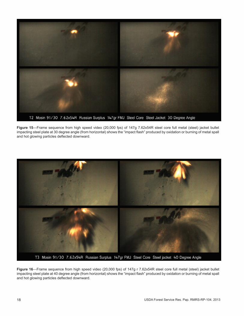
Figure 15—Frame sequence from high speed video (20,000 fps) of 147g 7.62x54R steel core full metal (steel) jacket bullet impacting steel plate at 30 degree angle (from horizontal) shows the “impact flash” produced by oxidation or burning of metal spall and hot glowing particles deflected downward.
Figure 16—Frame sequence from high speed video (20,000 fps) of 147g r 7.62x54R steel core full metal (steel) jacket bullet impacting steel plate at 40 degree angle (from horizontal) shows the “impact flash” produced by oxidation or burning of metal spall and hot glowing particles deflected downward.
19USDA Forest Service Res. Pap. RMRS-RP-104. 2013
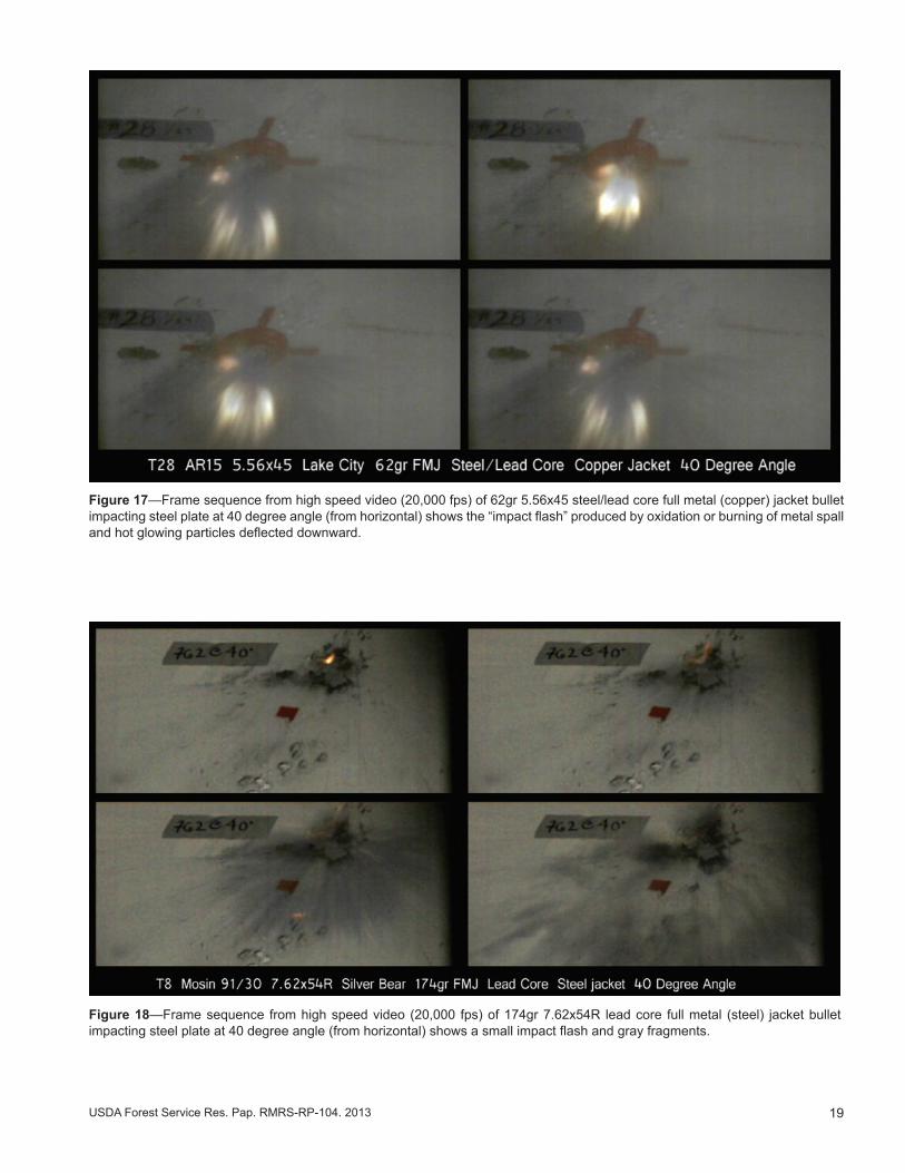
Figure 17—Frame sequence from high speed video (20,000 fps) of 62gr 5.56x45 steel/lead core full metal (copper) jacket bullet impacting steel plate at 40 degree angle (from horizontal) shows the “impact flash” produced by oxidation or burning of metal spall and hot glowing particles deflected downward.
Figure 18—Frame sequence from high speed video (20,000 fps) of 174gr 7.62x54R lead core full metal (steel) jacket bullet impacting steel plate at 40 degree angle (from horizontal) shows a small impact flash and gray fragments.
20 USDA Forest Service Res. Pap. RMRS-RP-104. 2013
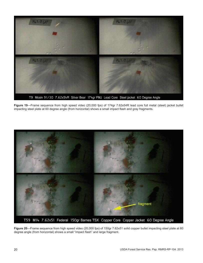
Figure 19—Frame sequence from high speed video (20,000 fps) of 174gr 7.62x54R lead core full metal (steel) jacket bullet impacting steel plate at 60 degree angle (from horizontal) shows a small impact flash and gray fragments.
Figure 20—Frame sequence from high speed video (20,000 fps) of 150gr 7.62x51 solid copper bullet impacting steel plate at 60 degree angle (from horizontal) shows a small “impact flash” and large fragment.
21USDA Forest Service Res. Pap. RMRS-RP-104. 2013
having a steel core displayed the greatest and longest-lasting flash (Figure 14-Figure 17). Smaller flash was visible from impact of bullets with lead core (Figure 18 & Figure 19) and of solid copper (Figure 20). Impact flash has been described as the burning of metal spall (oxidizing metal dust from the target and/or projectile) at temperatures of about 2700 °C (5000 °F) (Abernathy 1968, Mansur 1974). Its duration is very short and was visible in high speed video for less than 1/2000th of a second (<10 frames at ~20000 frames per second).
Temperatures of Bullet Fragments
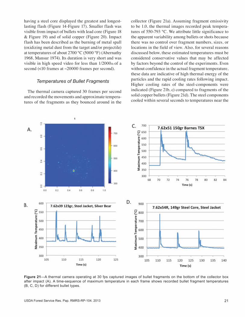
The thermal camera captured 30 frames per second and recorded the movements and approximate tempera-tures of the fragments as they bounced around in the
collector (Figure 21a). Assuming fragment emissivity to be 1.0, the thermal images recorded peak tempera-tures of 550-793 °C. We attribute little significance to the apparent variability among bullets or shots because there was no control over fragment numbers, sizes, or locations in the field of view. Also, for several reasons discussed below, these estimated temperatures must be considered conservative values that may be affected by factors beyond the control of the experiments. Even without confidence in the actual fragment temperature, these data are indicative of high thermal energy of the particles and the rapid cooling rates following impact. Higher cooling rates of the steel-components were indicated (Figure 21b, c) compared to fragments of the solid copper bullets (Figure 21d). The steel components cooled within several seconds to temperatures near the
Figure 21—A thermal camera operating at 30 fps captured images of bullet fragments on the bottom of the collector box after impact (A). A time-sequence of maximum temperature in each frame shows recorded bullet fragment temperatures (B, C, D) for different bullet types.
22 USDA Forest Service Res. Pap. RMRS-RP-104. 2013
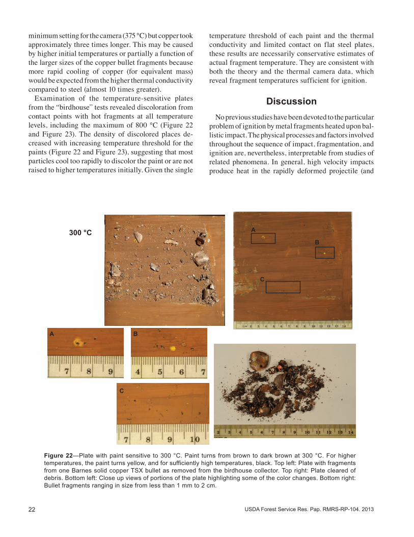
minimum setting for the camera (375 °C) but copper took approximately three times longer. This may be caused by higher initial temperatures or partially a function of the larger sizes of the copper bullet fragments because more rapid cooling of copper (for equivalent mass) would be expected from the higher thermal conductivity compared to steel (almost 10 times greater). Examination of the temperature-sensitive plates from the “birdhouse” tests revealed discoloration from contact points with hot fragments at all temperature levels, including the maximum of 800 °C (Figure 22 and Figure 23). The density of discolored places de-creased with increasing temperature threshold for the paints (Figure 22 and Figure 23), suggesting that most particles cool too rapidly to discolor the paint or are not raised to higher temperatures initially. Given the single
temperature threshold of each paint and the thermal conductivity and limited contact on flat steel plates, these results are necessarily conservative estimates of actual fragment temperature. They are consistent with both the theory and the thermal camera data, which reveal fragment temperatures sufficient for ignition.
Discussion No previous studies have been devoted to the particular problem of ignition by metal fragments heated upon bal-listic impact. The physical processes and factors involved throughout the sequence of impact, fragmentation, and ignition are, nevertheless, interpretable from studies of related phenomena. In general, high velocity impacts produce heat in the rapidly deformed projectile (and
Figure 22—Plate with paint sensitive to 300 °C. Paint turns from brown to dark brown at 300 °C. For higher temperatures, the paint turns yellow, and for sufficiently high temperatures, black. Top left: Plate with fragments from one Barnes solid copper TSX bullet as removed from the birdhouse collector. Top right: Plate cleared of debris. Bottom left: Close up views of portions of the plate highlighting some of the color changes. Bottom right: Bullet fragments ranging in size from less than 1 mm to 2 cm.
A
A
B
B
C
C
300 °C
23USDA Forest Service Res. Pap. RMRS-RP-104. 2013
possibly the target) that must quickly come to rest on a dry ignitable material. The rapid cooling of fragments, their small sizes, and odd shapes mean that fine-grained substrates such as peat provide more opportunity for direct contact and ignition. The toughness of different metals determines how much energy is required for deformation and fracturing, and thus, how much heat is generated when the particle material ultimately fails. This is why bullet construction is important to heating and ignition. Our study focused on laboratory testing of different bullets loaded in commercial ammunition. We observed that bullet material did affect fragment sizes and igni-tions, with steel components and solid copper bullets producing the largest fragments and the most likely ignitions in peat. Despite similar maximum temperatures recorded on thermal images, larger fragments from solid
copper bullets seem to be the most plausible explanation for the slower rates of temperature decline compared to steel seen in the image sequences (Figure 21). The op-posite trend would be expected based only on the greater thermal conductivity of copper than steel, meaning that heat loss rates should be greater for equivalent fragment mass. Both copper and steel are much “tougher” metals compared to lead, meaning that a greater amount of energy is required for plastic deformation at a particular strain rate. Lead therefore deforms with relatively little energy, and due to its relatively low melting temperature, will probably melt. The actual bullet fragment temperatures remain un-known, but they are consistent with the physical theory of plastic deformation under high strain rates. Maximum temperatures of about 550 °C to nearly 800 °C were recorded on thermal images for several bullet types
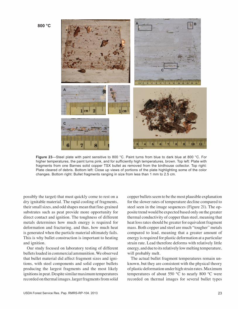
Figure 23—Steel plate with paint sensitive to 800 °C. Paint turns from blue to dark blue at 800 °C. For higher temperatures, the paint turns pink, and for sufficiently high temperatures, brown. Top left: Plate with fragments from one Barnes solid copper TSX bullet as removed from the birdhouse collector. Top right: Plate cleared of debris. Bottom left: Close up views of portions of the plate highlighting some of the color changes. Bottom right: Bullet fragments ranging in size from less than 1 mm to 2.5 cm.
800 °C
A
C
B
A
C
B
24 USDA Forest Service Res. Pap. RMRS-RP-104. 2013
and were consistent with the discoloration reaction by fragment contact with the temperature-sensitive paints. Both must be considered conservative estimates of the true fragment temperatures because:
1. The thermal camera was operated at 30 fps and could miss high temperatures of shorter duration.
2. There is an unknown and uncontrolled ratio of bullet fragment size relative to the pixel area in an image, which can lead to under-representing temperature due to partial pixel coverage by the fragment.
3. The emissivity of the bullet fragments is not known but assumed to be 1.0 for these calculations and which must therefore underrepresent the actual temperature.
4. Irregular particle geometry offers few contact points on a flat steel plate for discoloring the paints.
5. Thermal properties of the steel plate may diminish the paint response to small fragments.
This study intentionally did not address ignition by target material dislodged by the impact. Most ballistic impact studies are concerned with perforation or penetra-tion of the target, often metal, which may break away. Loose pieces of target metal can be fractured by similar deformation physics as described for the projectile, and it is possible that fires could ignite from them as well. From this study, an understanding of wildfire ignitions from field reports begins to emerge, but also involves other processes not encompassed by this work. The fol-lowing is a discussion of linkages to field-scale wildfire ignitions, given that the present study was confined to a laboratory apparatus and limited to detection of smoldering ignition very close to the target (<1m):
• Target materials that are highly resistant to dam-age would be similar to the steel plates and granite slabs tested here, such as boulders, rocks, or thick metal such as silhouettes. Oblique angles of impact may be important, regardless of target material, to producing larger fragments that would cool more slowly after contacting organic matter.
• Bullet materials clearly affect ignition potential, with steel components and solid copper having the greatest chance of producing hot fragments. We observed only one ignition from lead-core copper jacketed bullets.
• The very rapid particle cooling means the ignitions
are more likely nearer the target. Fragment size dis-tribution was not known or controlled, but smaller pieces cool so quickly that they must contact the suitable substrate very rapidly. The distances from a target that ignitions can occur are not determined by the present study.
• Ignitions are observed in the field only when the fire begins to spread. This is probably not when or where ignition actually takes place. The original ignition likely occurs in a material similar to peat, meaning partially decomposed organic matter in-corporated in the surface horizons of the soil – not the vegetation or fuel which carries the spreading fire with visible flames. The process of transition from smoldering incipient ignition to spreading fire may take some time (minutes to days, even weeks) depending on the fuel types and the weather and fuel conditions. Where the target is exposed to wind, a smoldering ignition in litter or duff may be ventilated easily and ignite grasses or surface litter and become visible more quickly than an area sheltered by trees or terrain.
• Consistent with previous research on particle igni-tion, the finding that dry excelsior could be ignited by the large pieces of solid copper bullets suggests that larger particles can start fires more easily, but small particles may require fine-grained or rotten material. This would require further testing beyond this study to determine however.
• Bullet fragments can be very small and still effec-tive in producing ignitions. The multiple ignitions observed in this experiment from small fragments of a single bullet means that it may be difficult to identify the exact piece of bullet material that causes an ignition under field conditions.
• As with all fire behavior and ignition research, moisture content of the organic material will be an important factor in ignition. Peat moisture contents of 3-5%, air temperatures of 34-49 °C (98-120 °F), and relative humidity of 7 to 16% were necessary to reliably observe ignitions in the experiments. Peat moisture contents above this (perhaps 8%) did not produce ignitions. Field conditions matching the experimental range would imply summer-time temperatures, as well as solar heating of the ground surface and organic matter to produce a drier and warmer microclimate where bullet fragments are deposited.
25USDA Forest Service Res. Pap. RMRS-RP-104. 2013
Acknowledgments Conducting this study depended on the support and ingenuity of many people. Chuck Harding constructed the bullet trap. Jack Kautz, Randy Pryhorocki, and Andrew Gorris built and designed the laboratory shooting range apparatus including external sound suppressor, birdhouse attachment to the deflector, and granite attachment assembly. Mark Vosburgh, Amanda Deter-man, and Dan Jimenez took responsibility for video imagery. Jay Fronden and Jason Forthofer assisted in all phases of the shooting tests. Mike Bonzano ensured range safety for the laboratory tests. Dave Ball of the Missoula County Sheriff’s Department graciously helped with the access and use of the out-door range. Isaac Grenfell provided data processing and statistical advice and analysis. Shari Kappel and Corrie Kegel oversaw safety and security plans for the indoor testing. This report was greatly improved from the review comments provided by Don Latham, Vytensis Babrauskas, Steve Mates, and John Fehr.
26 USDA Forest Service Res. Pap. RMRS-RP-104. 2013
ReferencesAbernathy, J.B. 1968. Ballistic impact flash. Masters Thesis. Wright-
Patterson Air Force Base, OH: School of Engineering of the Air Force Institute of Technology, Air University. 50 p.
Babrauskas, V. 2003. Ignition Handbook. Issaquah, WA: Fire Sci-ence Publishers: 238-239;287-289; 500-509; 842-844.
Christiensen, R. 1998. Bonferonni Adjustments. In: Analysis of variance, design, and regression. Boca Raton, FL: Chapman & Hall: 152.
Churchill, S. W., and M. Bernstein. 1977. A correlating equation for forced convection from gases and liquids to a circular cylinder in crossflow. ASME Transactions Journal of Heat Transfer. 99: 300-306.
Ellis, P.F. 2000. The aerodynamic and combustion Ccharacteristics of eucalypt bark – A firebrand study. Ph.D. dissertation. Canberra: Australian National University.
Frandsen, W.H. 1987. The influence of moisture and mineral soil on the combustion limits of smoldering forest duff. Canadian Journal of Forest Research. 17: 1540-1544.
Frandsen, W.H. 1997. Ignition probability of organic soils. Canadian Journal of Forest Research. 27: 1471-1477.
Gol’dshleger, U.I., V.V. Barzykin, and T.P. Ivleva. 1973. Ignition of condensed explosives by a hot spherical object. Combustion, Explosion, and Shock Waves. 9(5): 642-647.
Goldsmith, W. 1999. Non-ideal projectile impact on targets. Inter-national Journal of Impact Engeering. 22:95-395.
Grishin, A.M., A.N. Golovanov, Y.V. Sukov, and Y.I. Preis. 2006. Experimental study of peat ignition and combustion. Journal of Engineering Physics and Thermophysics. 79(3): 563-568.
Hadden, R.M., S. Scott, C. Lautenberger, and A.C. Fernandez-Pello. 2011. Ignition of combustible fuel beds by hot particles: An ex-perimental and theoretical study. Fire Technology. 47: 341-355.
Hartford, R.A. 1989. Smoldering combustion limits in peat as in-fluenced by moisture, mineral content, and organic bulk density. In: MacIver, D.C., H. Auld, and R. Whitewood, eds. Proceedings of the 10th Conference on Fire and Forest Meteorology; April 1989; Ottawa, Ontario. Chalk River, Ontario: Forestry Canada, Petawawa National Forestry Institute: 282-286.
Incropera F.P., and D. P. DeWitt. 2002. Introduction to Heat Transfer. New York: Wiley.
Johnson, W., A.K. Sengupta, and S.K. Ghosh. 1982. High veloc-ity oblique impact and ricochet mainly of long rod projectiles: An overview. International Journal of Mechanical Sciences. 24(7):425-436.
Kapoor, R., and S. Nemat-Nasser. 1998. Determination of tem-perature rise during high strain rate deformation. Mechanics of Materials. 27(1),: 1-12.
Kuchta, J.M., A.L. Furno, and G.H. Martindill. 1969. Flammability of fabrics and other materials in oxygen-enriched atmospheres. Part 1. Ignition temperatures and flame spread rates. Fire Tech-nology. 5: 203-216.
Mansur, J.W. 1974. Measurement of ballistic impact flash. Masters Thesis. Wright-Patterson Air Force Base, OH: School of Engineer-ing of the Air Force Institute of Technology, Air University. 51 p.
Manzello, S.L., T.G. Cleary, J.R. Shields, and J.C. Yang. 2006a. On the ignition of fuel beds by firebrands. Fire and Materials. 30:77-87.
Manzello, S.L., T.G. Cleary, J.R. Shields, and J.C. Yang. 2006b. Ignition of mulch and grasses by firebrands in wildland-urban interface fires. International Journal of Wildland Fire 15: 427-431.
Manzello, S.L., T.G. Cleary, J.R. Shields, A. Maranghides, W. Mell, and J.C. Yang. 2008. Experimental investigation of firebrands: generation and ignition of fuel beds. Fire Safety Journal. 43: 226-233.
McGuire, J. H., M. Law, and J.E. Miller. 1956. Domestic fire hazard created by flying coals and sparks (FR Note 252). Borehamwood, England: Fire Research Station.
Molinari, J.F., and M. Ortiz. 2002. A study of solid-particle erosion of metallic targets. International Journal of Impact Engineering. 27:447-358.
National Wildfire Coordinating Group. 2005. Wildfire origin and cause determination handbook 1. PMS 412-1. Boise, ID: National Wildfire Coordinating Group, Fire Investigation Working Team. 111 p.
Oberg, E., F.D. Jones, and H.L. Horton. 1990. Machinery’s handbook, 23rd edition. South Norwalk, CT: Industrial Press.
Ohlemiller, T.J. 2008. Smoldering combustion. In: DiNenno and others, eds. The SFPE Handbook of Fire Protection Engineering, 4th edition. Quincy, MA: NFPA, p. 2-229 - 2-240.
Pineda, N., J. Montanyà, O.A. van der Velde. In Press. Characteristics of lightning related to wildfire ignitions in Catalonia. Atmospheric Research. http://dx.doi.org/10.1016/j.atmosres.2012.07.011.
Popov, E.P. 1976. Mechanics of materials .- 2nd edition. Upper Saddle River, NJ: Prentice Hall.
Quinney, H., and G.I. Taylor. 1937. The emission of the latent energy due to previous cold working when a metal is heated. Proceed-ings of the Royal Society of London. Series A-Mathematical and Physical Sciences. 163(913): 157-181.
Ravichandra, G., A. Roaskia, J. Hodowany, P. Rosakis. 2002. On the conversion of plastic work into heat during high strain rate deformation. In: Shock Compression of Condensed Matter; Proceedings of the conference of the American Physical Society, Topical Group on shock compression of condensed matter; June 14-19 2001; Atlanta, GA: 557-562
Rein, G. 2009. Smouldering combustion phenomena in science and technology. International Review of Chemical Engineer-ing. 1: 3-18.
Rittel, D., and S. Osovski. 2010. Dynamic failure by adiabatic shear banding. International Journal of Fracture. 162(1-2): 177-185.
Rogers, H.C. 1979. Adiabatic plastic deformation. Annual Review of Materials Science. 9(1): 283-311.
Rowntree, G.W.G., and A.D. Stokes. 1994. Fire ignition by aluminum particles of controlled size. Journal of Electrical and Electronics Engineering, Australia. 14(2): 117-123.
Setchkin, N.P. 1949. A method and apparatus for determining the ignition characteristics of plastics, Journal Research NBS. 43: 591-608.
Stokes, A.D. 1990. Fire ignition by copper particles of controlled size. Journal of Electrical and Electronics Engineering, Australia. 10(3): 188-194.
Tanaka, T. 1977. On the inflammability of combustible materials by welding spatter. Reports of the National Research Institute of Police Science. 30(1): 51-58.
Torero, J.L. 2008. Flaming ignition of solid fuels. In: DiNenno and others, eds. The SFPE Handbook of Fire Protection Engineering, 4th edition. Quincy, MA: NFPA, p. 2-260 - 2-277.
Tse, S. and A.C. Fernandez-Pello. 1998. On the flight paths of metal particles and embers generated by power lines in high winds – a potential source of wildland fires. Fire Safety Journal. 30:333-356.
U.S. Army. 1994. Army ammunition data sheets: Small caliber ammunition – FSC 1305. Technical Manual TM 43-0001-27. Washington, DC: U.S. Government Printing Office. 1994-546-043:80742.
Wotton, B.M. and D.L. Martell. 2005. A lightning occurrence model for Ontario. Canadian Journal of Forest Research. 35:1389-1401.
Xiao, X., W. Zhang, G. Wei, and Z. Mu. 2010. Effect of projectile hardness on deformation and fracture behavior in the Taylor impact test. Materials & Design. 31(10): 4913-4920.
Yildirim, B., S. Muftu, and A. Gouldstone. 2011. Modeling of high velocity impact of spherical particles. Wear. 270:703-713.
27USDA Forest Service Res. Pap. RMRS-RP-104. 2013
App
endi
x—D
ata
obta
ined
from
sho
otin
g te
sts.
Red
sha
ding
indi
cate
s te
sts
whe
re ig
nitio
ns w
ere
obse
rved
. Yel
low
sh
adin
g in
dica
tes
ambi
guou
s re
sult
(see
com
men
ts)
Dat
eTe
st
num
ber
Targ
et
mat
eria
lC
artr
idge
Man
ufac
ture
rB
ulle
t typ
eA
ngle
Mat
eria
lN
umbe
r of
rou
nds
Num
ber
of
igni
tions
Avg
muz
zle
velo
city
Com
men
ts
Wei
ght
Cor
eJa
cket
Deg
ft s-1
Out
door
Tes
ts
9/21
/201
2x8
stee
l5.
56x4
5m
855
62gr
Stee
l/Le
adC
oppe
r30
Peat
110
9/21
/201
2x9
stee
l7.
62x5
4RH
unga
rian
Surp
lus
180g
r FM
JSt
eel/
Lead
Stee
l30
Peat
52
9/21
/201
2x1
0st
eel
7.62
x54R
Hun
garia
n Su
rplu
s18
0gr F
MJ
Stee
l/Le
adSt
eel
20Pe
at5
5
9/21
/201
2x1
1st
eel
7.62
x39
Silv
er B
ear
123g
r FM
JLe
adSt
eel
20Pe
at7
7
Rifl
e: R
ussi
an M
osin
-Nag
ant 9
1/30
1/22
/201
31
stee
l7.
62x5
4RR
ussi
an S
urpl
us14
7gr F
MJ
Stee
lSt
eel
20Pe
at5
428
13
1/22
/201
32
stee
l7.
62x5
4RR
ussi
an S
urpl
us14
7gr F
MJ
Stee
lSt
eel
30Pe
at5
228
27
1/22
/201
33
stee
l7.
62x5
4RR
ussi
an S
urpl
us14
7gr F
MJ
Stee
lSt
eel
40Pe
at5
228
13
1/22
/201
34
stee
l7.
62x5
4RR
ussi
an S
urpl
us14
7gr F
MJ
Stee
lSt
eel
60Pe
at5
427
76
1/22
/201
35
stee
l7.
62x5
4RR
ussi
an S
urpl
us14
7gr F
MJ
Stee
lSt
eel
80Pe
at5
128
06
1/22
/201
36
stee
l7.
62x5
4RSi
lver
Bea
r17
4gr F
MJ
Lead
Stee
l20
Peat
54
2595
1/22
/201
37
stee
l7.
62x5
4RSi
lver
Bea
r17
4gr F
MJ
Lead
Stee
l30
Peat
50
1/22
/201
38
stee
l7.
62x5
4RSi
lver
Bea
r17
4gr F
MJ
Lead
Stee
l40
Peat
50
1/22
/201
39
stee
l7.
62x5
4RSi
lver
Bea
r17
4gr F
MJ
Lead
Stee
l60
Peat
50
2592
1/22
/201
310
stee
l7.
62x5
4RSi
lver
Bea
r17
4gr F
MJ
Lead
Stee
l80
Peat
50
2603
1/23
/201
311
stee
l7.
62x5
4RW
inch
este
r18
0gr J
SPLe
adC
oppe
r20
Peat
50
2641
1/23
/201
312
stee
l7.
62x5
4RW
inch
este
r18
0gr J
SPLe
adC
oppe
r30
Peat
50
2657
1/23
/201
313
stee
l7.
62x5
4RW
inch
este
r18
0gr J
SPLe
adC
oppe
r40
Peat
50
2639
1/23
/201
314
stee
l7.
62x5
4RW
inch
este
r18
0gr J
SPLe
adC
oppe
r60
Peat
50
2647
1/23
/201
315
stee
l7.
62x5
4RW
inch
este
r18
0gr J
SPLe
adC
oppe
r80
Peat
50
2634
Rifl
e: A
K47
, Ars
enal
SA
-M7A
1R
1/23
/201
316
stee
l7.
62x3
9Si
lver
Bea
r12
3gr F
MJ
Lead
Stee
l20
Peat
50
2325
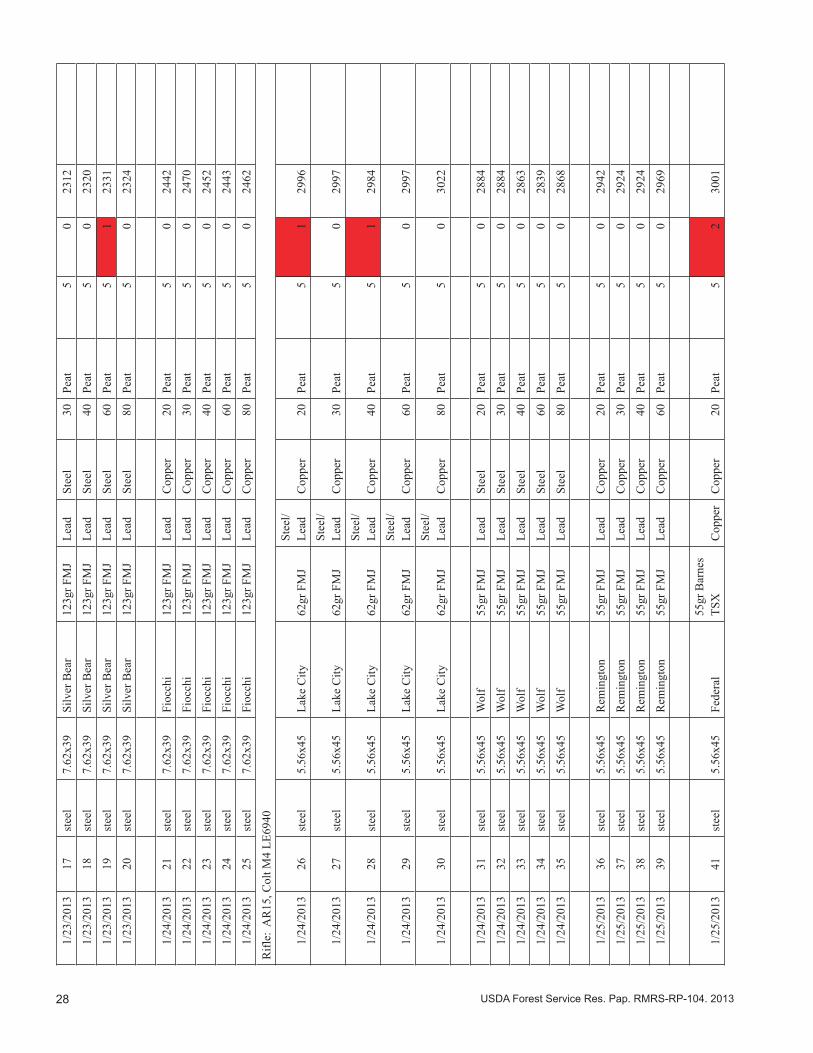
28 USDA Forest Service Res. Pap. RMRS-RP-104. 2013
1/23
/201
317
stee
l7.
62x3
9Si
lver
Bea
r12
3gr F
MJ
Lead
Stee
l30
Peat
50
2312
1/23
/201
318
stee
l7.
62x3
9Si
lver
Bea
r12
3gr F
MJ
Lead
Stee
l40
Peat
50
2320
1/23
/201
319
stee
l7.
62x3
9Si
lver
Bea
r12
3gr F
MJ
Lead
Stee
l60
Peat
51
2331
1/23
/201
320
stee
l7.
62x3
9Si
lver
Bea
r12
3gr F
MJ
Lead
Stee
l80
Peat
50
2324
1/24
/201
321
stee
l7.
62x3
9Fi
occh
i12
3gr F
MJ
Lead
Cop
per
20Pe
at5
024
42
1/24
/201
322
stee
l7.
62x3
9Fi
occh
i12
3gr F
MJ
Lead
Cop
per
30Pe
at5
024
70
1/24
/201
323
stee
l7.
62x3
9Fi
occh
i12
3gr F
MJ
Lead
Cop
per
40Pe
at5
024
52
1/24
/201
324
stee
l7.
62x3
9Fi
occh
i12
3gr F
MJ
Lead
Cop
per
60Pe
at5
024
43
1/24
/201
325
stee
l7.
62x3
9Fi
occh
i12
3gr F
MJ
Lead
Cop
per
80Pe
at5
024
62
Rifl
e: A
R15
, Col
t M4
LE69
40
1/24
/201
326
stee
l5.
56x4
5La
ke C
ity62
gr F
MJ
Stee
l/Le
adC
oppe
r20
Peat
51
2996
1/24
/201
327
stee
l5.
56x4
5La
ke C
ity62
gr F
MJ
Stee
l/Le
adC
oppe
r30
Peat
50
2997
1/24
/201
328
stee
l5.
56x4
5La
ke C
ity62
gr F
MJ
Stee
l/Le
adC
oppe
r40
Peat
51
2984
1/24
/201
329
stee
l5.
56x4
5La
ke C
ity62
gr F
MJ
Stee
l/Le
adC
oppe
r60
Peat
50
2997
1/24
/201
330
stee
l5.
56x4
5La
ke C
ity62
gr F
MJ
Stee
l/Le
adC
oppe
r80
Peat
50
3022
1/24
/201
331
stee
l5.
56x4
5W
olf
55gr
FM
JLe
adSt
eel
20Pe
at5
028
84
1/24
/201
332
stee
l5.
56x4
5W
olf
55gr
FM
JLe
adSt
eel
30Pe
at5
028
84
1/24
/201
333
stee
l5.
56x4
5W
olf
55gr
FM
JLe
adSt
eel
40Pe
at5
028
63
1/24
/201
334
stee
l5.
56x4
5W
olf
55gr
FM
JLe
adSt
eel
60Pe
at5
028
39
1/24
/201
335
stee
l5.
56x4
5W
olf
55gr
FM
JLe
adSt
eel
80Pe
at5
028
68
1/25
/201
336
stee
l5.
56x4
5R
emin
gton
55gr
FM
JLe
adC
oppe
r20
Peat
50
2942
1/25
/201
337
stee
l5.
56x4
5R
emin
gton
55gr
FM
JLe
adC
oppe
r30
Peat
50
2924
1/25
/201
338
stee
l5.
56x4
5R
emin
gton
55gr
FM
JLe
adC
oppe
r40
Peat
50
2924
1/25
/201
339
stee
l5.
56x4
5R
emin
gton
55gr
FM
JLe
adC
oppe
r60
Peat
50
2969
1/25
/201
341
stee
l5.
56x4
5Fe
dera
l55
gr B
arne
s TS
XC
oppe
rC
oppe
r20
Peat
52
3001
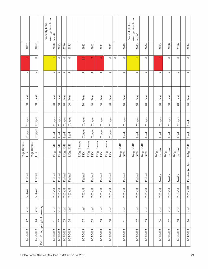
29USDA Forest Service Res. Pap. RMRS-RP-104. 2013
1/25
/201
342
stee
l5.
56x4
5Fe
dera
l55
gr B
arne
s TS
XC
oppe
rC
oppe
r30
Peat
51
3027
1/25
/201
344
stee
l5.
56x4
5Fe
dera
l55
gr B
arne
s TS
XC
oppe
rC
oppe
r60
Peat
50
3052
Rifl
e: M
1A, S
prin
gfie
ld A
rmor
y
1/25
/201
351
stee
l7.
62x5
1Fe
dera
l15
0gr F
MJ
Lead
Cop
per
20Pe
at5
128
88
Prob
ably
hol
d-
over
igni
tion
from
te
st 4
4
1/25
/201
352
stee
l7.
62x5
1Fe
dera
l15
0gr F
MJ
Lead
Cop
per
30Pe
at5
028
83
1/25
/201
353
stee
l7.
62x5
1Fe
dera
l15
0gr F
MJ
Lead
Cop
per
40Pe
at5
027
96
1/25
/201
354
stee
l7.
62x5
1Fe
dera
l15
0gr F
MJ
Lead
Cop
per
60Pe
at5
028
35
1/25
/201
357
stee
l7.
62x5
1Fe
dera
l15
0gr B
arne
s TS
XC
oppe
rC
oppe
r30
Peat
512
2913
1/25
/201
358
stee
l7.
62x5
1Fe
dera
l15
0gr B
arne
s TS
XC
oppe
rC
oppe
r40
Peat
57
2903
1/25
/201
359
stee
l7.
62x5
1Fe
dera
l15
0gr B
arne
s TS
XC
oppe
rC
oppe
r60
Peat
56
2831
1/25
/201
360
stee
l7.
62x5
1Fe
dera
l15
0gr B
arne
s TS
XC
oppe
rC
oppe
r80
Peat
50
2832
0
1/25
/201
361
stee
l7.
62x5
1Fe
dera
l16
8gr S
MK
O
TMLe
adC
oppe
r20
Peat
50
2649
1/25
/201
362
stee
l7.
62x5
1Fe
dera
l16
8gr S
MK
O
TMLe
adC
oppe
r30
Peat
51
2645
Prob
able
hol
d-ov
er ig
nitio
n fr
om
test
60
1/25
/201
363
stee
l7.
62x5
1Fe
dera
l16
8gr S
MK
O
TMLe
adC
oppe
r40
Peat
50
2634
1/25
/201
366
stee
l7.
62x5
1N
osle
r16
5gr
Parti
tion
Lead
Cop
per
20Pe
at5
128
75
1/25
/201
367
stee
l7.
62x5
1N
osle
r16
5gr
Parti
tion
Lead
Cop
per
30Pe
at5
028
60
1/25
/201
368
stee
l7.
62x5
1N
osle
r16
5gr
Parti
tion
Lead
Cop
per
40Pe
at5
027
86
1/23
/201
376
stee
l7.
62x5
4RR
ussi
an S
urpl
us14
7gr F
MJ
Stee
lSt
eel
40Pe
at5
028
34
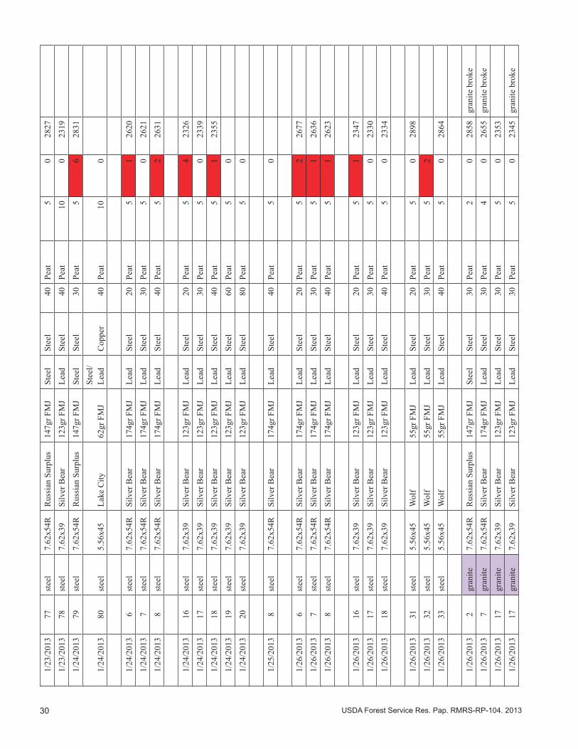
30 USDA Forest Service Res. Pap. RMRS-RP-104. 2013
1/23
/201
377
stee
l7.
62x5
4RR
ussi
an S
urpl
us14
7gr F
MJ
Stee
lSt
eel
40Pe
at5
028
27
1/23
/201
378
stee
l7.
62x3
9Si
lver
Bea
r12
3gr F
MJ
Lead
Stee
l40
Peat
100
2319
1/24
/201
379
stee
l7.
62x5
4RR
ussi
an S
urpl
us14
7gr F
MJ
Stee
lSt
eel
30Pe
at5
628
31
1/24
/201
380
stee
l5.
56x4
5La
ke C
ity62
gr F
MJ
Stee
l/Le
adC
oppe
r40
Peat
100
1/24
/201
36
stee
l7.
62x5
4RSi
lver
Bea
r17
4gr F
MJ
Lead
Stee
l20
Peat
51
2620
1/24
/201
37
stee
l7.
62x5
4RSi
lver
Bea
r17
4gr F
MJ
Lead
Stee
l30
Peat
50
2621
1/24
/201
38
stee
l7.
62x5
4RSi
lver
Bea
r17
4gr F
MJ
Lead
Stee
l40
Peat
52
2631
1/24
/201
316
stee
l7.
62x3
9Si
lver
Bea
r12
3gr F
MJ
Lead
Stee
l20
Peat
54
2326
1/24
/201
317
stee
l7.
62x3
9Si
lver
Bea
r12
3gr F
MJ
Lead
Stee
l30
Peat
50
2339
1/24
/201
318
stee
l7.
62x3
9Si
lver
Bea
r12
3gr F
MJ
Lead
Stee
l40
Peat
51
2355
1/24
/201
319
stee
l7.
62x3
9Si
lver
Bea
r12
3gr F
MJ
Lead
Stee
l60
Peat
50
1/24
/201
320
stee
l7.
62x3
9Si
lver
Bea
r12
3gr F
MJ
Lead
Stee
l80
Peat
50
1/25
/201
38
stee
l7.
62x5
4RSi
lver
Bea
r17
4gr F
MJ
Lead
Stee
l40
Peat
50
1/26
/201
36
stee
l7.
62x5
4RSi
lver
Bea
r17
4gr F
MJ
Lead
Stee
l20
Peat
52
2677
1/26
/201
37
stee
l7.
62x5
4RSi
lver
Bea
r17
4gr F
MJ
Lead
Stee
l30
Peat
51
2636
1/26
/201
38
stee
l7.
62x5
4RSi
lver
Bea
r17
4gr F
MJ
Lead
Stee
l40
Peat
51
2623
1/26
/201
316
stee
l7.
62x3
9Si
lver
Bea
r12
3gr F
MJ
Lead
Stee
l20
Peat
51
2347
1/26
/201
317
stee
l7.
62x3
9Si
lver
Bea
r12
3gr F
MJ
Lead
Stee
l30
Peat
50
2330
1/26
/201
318
stee
l7.
62x3
9Si
lver
Bea
r12
3gr F
MJ
Lead
Stee
l40
Peat
50
2334
1/26
/201
331
stee
l5.
56x4
5W
olf
55gr
FM
JLe
adSt
eel
20Pe
at5
028
98
1/26
/201
332
stee
l5.
56x4
5W
olf
55gr
FM
JLe
adSt
eel
30Pe
at5
2
1/26
/201
333
stee
l5.
56x4
5W
olf
55gr
FM
JLe
adSt
eel
40Pe
at5
028
64
1/26
/201
32
gran
ite7.
62x5
4RR
ussi
an S
urpl
us14
7gr F
MJ
Stee
lSt
eel
30Pe
at2
028
58gr
anite
bro
ke
1/26
/201
37
gran
ite7.
62x5
4RSi
lver
Bea
r17
4gr F
MJ
Lead
Stee
l30
Peat
40
2655
gran
ite b
roke
1/26
/201
317
gran
ite7.
62x3
9Si
lver
Bea
r12
3gr F
MJ
Lead
Stee
l30
Peat
50
2353
1/26
/201
317
gran
ite7.
62x3
9Si
lver
Bea
r12
3gr F
MJ
Lead
Stee
l30
Peat
50
2345
gran
ite b
roke
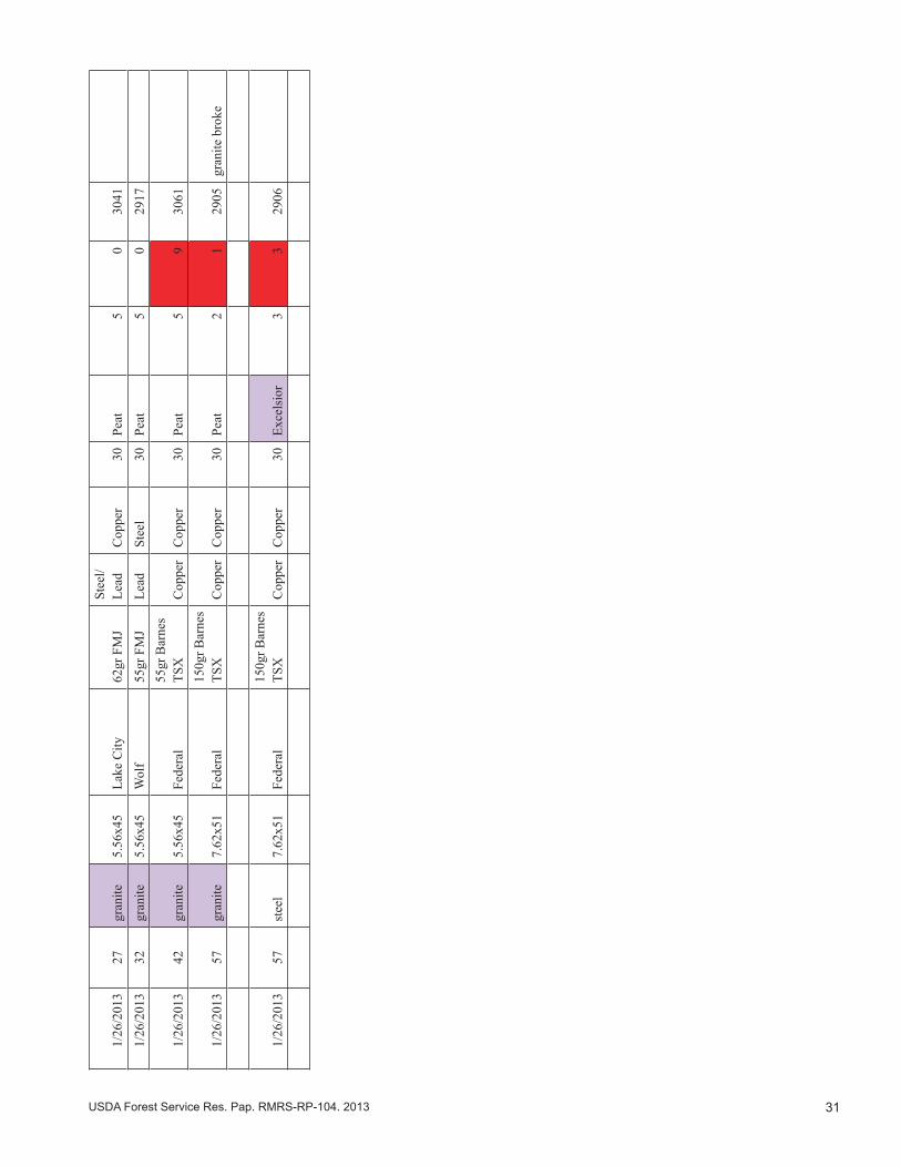
31USDA Forest Service Res. Pap. RMRS-RP-104. 2013
1/26
/201
327
gran
ite5.
56x4
5La
ke C
ity62
gr F
MJ
Stee
l/Le
adC
oppe
r30
Peat
50
3041
1/26
/201
332
gran
ite5.
56x4
5W
olf
55gr
FM
JLe
adSt
eel
30Pe
at5
029
17
1/26
/201
342
gran
ite5.
56x4
5Fe
dera
l55
gr B
arne
s TS
XC
oppe
rC
oppe
r30
Peat
59
3061
1/26
/201
357
gran
ite7.
62x5
1Fe
dera
l15
0gr B
arne
s TS
XC
oppe
rC
oppe
r30
Peat
21
2905
gran
ite b
roke
1/26
/201
357
stee
l7.
62x5
1Fe
dera
l15
0gr B
arne
s TS
XC
oppe
rC
oppe
r30
Exce
lsio
r3
329
06
The Rocky Mountain Research Station develops scientific information and technology to improve management, protection, and use of the forests and rangelands. Research is designed to meet the needs of the National Forest managers, Federal and State agencies, public and private organizations, academic institutions, industry, and individuals. Studies accelerate solutions to problems involving ecosystems, range, forests, water, recreation, fire, resource inventory, land reclamation, community sustainability, forest engineering technology, multiple use economics, wildlife and fish habitat, and forest insects and diseases. Studies are conducted cooperatively, and applications may be found worldwide. For more information, please visit the RMRS web site at: www.fs.fed.us/rmrs.
Station Headquarters Rocky Mountain Research Station
240 W Prospect RoadFort Collins, CO 80526
(970) 498-1100
Research Locations
The U.S. Department of Agriculture (USDA) prohibits discrimination against its customers, employees, and applicants for employment on the bases of race, color, national origin, age, disability, sex, gender identity, religion, reprisal, and where applicable, political beliefs, marital status, familial or parental status, sexual orientation, or all or part of an individual’s income is derived from any public assistance program, or protected genetic information in employment or in any program or activity conducted or funded by the Department. (Not all prohibited bases will apply to all programs and/or employment activities.) For more information, please visit the USDA web site at: www.usda.gov and click on the Non-Discrimination Statement link at the bottom of the page.
Reno, NevadaAlbuquerque, New MexicoRapid City, South Dakota
Logan, UtahOgden, UtahProvo, Utah
Flagstaff, ArizonaFort Collins, Colorado
Boise, IdahoMoscow, Idaho
Bozeman, MontanaMissoula, Montana
To learn more about RMRS publications or search our online titles:
www.fs.fed.us/rm/publications
www.treesearch.fs.fed.us
Federal Recycling Program Printed on Recycled Paper