Embed Size (px)
Citation preview

A STUDY ON LOAD BEARING CAPACITY OF
SANDWICH WALL PANELS
Rupasinghe Arachchige Don Lalindra Jayamevan Rupasinghe
(09/8927)
Degree of Master of Engineering in Structural Engineering Designs
Department of Civil Engineering
University of Moratuwa
Sri Lanka
January 2013

A STUDY ON LOAD BEARING CAPACITY OF
SANDWICH WALL PANELS
Rupasinghe Arachchige Don Lalindra Jayamevan Rupasinghe
(09/8927)
Dissertation submitted in partial fulfillment of the requirements for
the degree Master of Engineering in Structural Engineering
Department of Civil Engineering
University of Moratuwa
Sri Lanka
January 2013
i
Declaration
I declare that this is my own work and this dissertation does not incorporate without
acknowledgement any material previously submitted for a Degree or Diploma in any
other University or institute of higher learning and to the best of my knowledge and
belief it does not contain any material previously published or written by another
person except where the acknowledgement is made in the text.
Also, I hereby grant to University of Moratuwa the non-exclusive right to reproduce
and distribute my dissertation, in whole or in part in print, electronic or other
medium. I retain the right to use this content in whole or part in future works (such
as article or books).
Signature: ………………………………… Date:……………………….
R.A.D.L.J. Rupasinghe
(09 / 8927)
The above candidate has carried out research for the Masters Dissertation under my
supervision.
Signature: ………………………………… Date:……………………….
Research Supervisor
Dr.K.Baskaran
Senior Lecturer
ii
Abstract
Sandwich wall panel technology is a new system introduced to Sri Lanka. Thermal insulation, sound insulation, light weight and reduction in natural resources like sand have lead to its popularity in Sri Lanka. The system is faster in construction than conventional wall systems. The sandwich wall panel system is used in Sri Lanka as partitioned walls in construction industry today. Load from above floors are taken by separate column and beam system. If accurate load bearing estimate is available, it can minimize or omit use of other load bearing systems. The scope of this research was to recognize suitability of available codes and to identify the reduction in load bearing capacity due to a window opening in a sandwich wall panel. In this dissertation, method of production of locally available sandwich wall panels and load bearing capacity according to available literature are presented. Three 1200mm width, 100mm thick and 2400mm high sandwich wall panels were cast. Out of these three, two panels had openings to represent windows. The panels were tested in axial compression while monitoring transverse deflection at mid height of the panel. All three panels’ ultimate load bearing capacity was nearly equal. Only one panel had higher degree of lateral movement while loading. All panels have shown local crushing failure near top and bottom loading points. Three sandwich panel blocks of 600mm length, 100mm thick and 300mm height were tested in a Universal testing machine to get ultimate load bearing capacity. The blocks’ ultimate load bearing capacities are also nearly equall to that of 2400mm height panels. Six numbers of 150mm mortar cubes were also tested in Universal testing machine to find ultimate compressive strength. Samples of diagonal shear connecters (Gauge 9 GI wire) were cut out from specimen and tested for compression capacity in Universal timber testing machine. The samples failed in buckling. 100mm high samples had about 0.7kN compression capacity. It was concluded that 600mm width and 900mm high opening in the given orientation did not affect load bearing capacity of panel. Key words: Sandwich wall panel, Load bearing capacity, openings, wythe, insulation layer.

iii
Acknowledgement
I wish to express my sincere gratitude to my research supervisor Dr.K.Baskaran,
Senior Lecturer, Department of Civil Engineering, University of Moratuwa, Sri
Lanka for his guidance, suggestions and continuous support throughout my research
work.
I also extend my sincere gratitude to the Head of Department of Civil Engineering,
University of Moratuwa, Sri Lanka for allowing me to use the laboratory facilities
and the resources available at the university, for successful completion of my
research project.
I wish to thank the Micro Construction (Pvt) Ltd for providing sandwich panels and
other test samples for the research. Their kind assistance and knowledge helped me
for the success of my research.
I would like to take this opportunity to convey my sincere gratitude to
Mr.H.N.Fernando (Lab Assistant-Structural Testing Laboratory) for the assistance
extended to me in numerous ways throughout this period.
I also extend my appreciation to my family for the valued cooperation and
encouragement received to make my M. Eng. programme a success.

iv
Table of Contents
Abstract ii
Acknowledgement iii
Table of content iv
List of Figures vii
List of Tables ix
List of Abbreviations x
1. Introduction 01
1.1 General Introduction 01
1.2 Research Objectives 03
1.3 Research Scope 03
1.4 Outline of the Report 03
2. Literature Review 04
2.1 General Introduction 04
2.2 Materials use for sandwich wall panels 05
2.2.1 Wythes 05
2.2.2 Shear Connectors 05
2.2.3 Insulation 07
2.2.4 Steel reinforcements for wythes 09
2.3 Precast panel sizes 09
2.4 Bowing in sandwich wall panels 10
2.5 Thermal performance 10
2.6 Composite and non-composite behaviour of sandwich wall panel 11
2.7 Axial load bearing capacity 13
2.8 Flexural loading capacity of SWP 24
2.9 Summary 28
v
3. Experimental Study 30
3.1 General Introduction 30
3.2 Equipments used to produce SWP 31
3.2.1 Cement mortar sprayer 31
3.2.2 Pair of pliers 33
3.2.3 Pneumatic “c” ring gun 33
3.2.4 Air compressor 34
3.3. Panel casting 35
3.4 150mm Test cube casting 38
3.5 Testing panels under axial compression load 39
3.6 Testing small SWP blocks for compression 42
3.7 Testing mortar test cubes for compression 43
3.8 Testing gauge 9 GI wire diagonal members in compression 43
4. Analysis and Discussion of Results 44
4.1 General Introduction 44
4.2 Experimental results 44
4.2.1 Panel A 44
4.2.2 Panel B 46
4.2.3 Panel C 47
4.2.4 600mm x 100mm x 300mm Blocks in axial compression 49
4.2.5 150mm Mortar cubes in compression 50
4.2.6 Gauge 9 GI wires in compression 50
4.3 Summary of test results 50
4.4 Estimation of axial load capacity according to literature 51
4.4.1 BOCA (1999) 51
4.4.2 ICBO (1999) 52

vi
4.5 Discussion 53
4.5.1 Comparison of Panel A with BOCA (1999) 53
4.5.2 Comparison between Panel A and ICBO (1999) 53
4.5.3 Load bearing reduction due to opening 53
4.5.4 Compression capacity of SWP blocks 54
4.5.5 Comparison of SWP blocks and panels with BS 5628-1 54
4.5.6 Finite element modelling 56
5. Conclusions and Recommendations 57
5.1 General Introduction 57
5.2 Conclusions 57
5.3 Recommendations for Future Works 57
References 59

vii
List of Figures
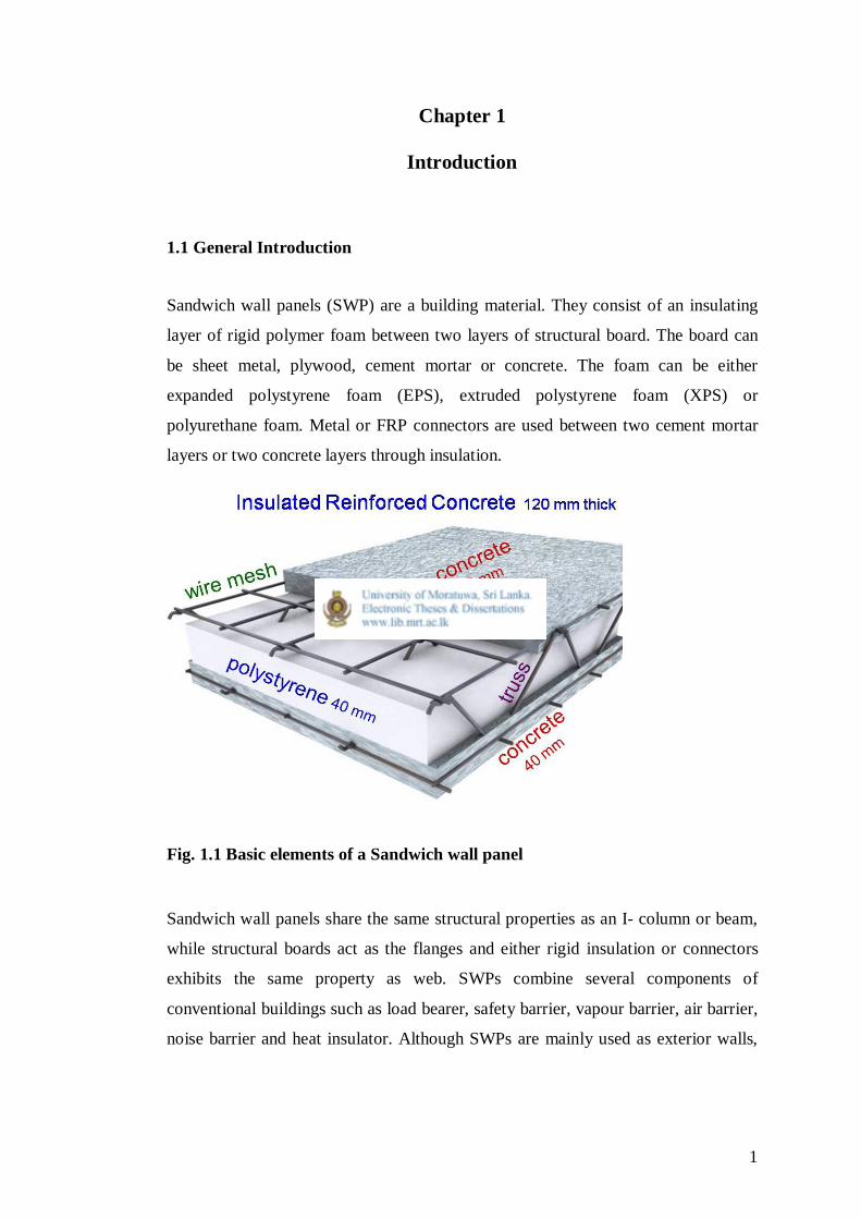
Figure 1.1 Basic elements of a sandwich wall panel 01
Figure 2.1 Examples for shear connectors 06
Figure 2.2 Non composite and fully composite panels’ theoretical behaviour 11
Figure 2.3 Test set-up and test frame of Benayoune et al. (2005a) 16
Figure 2.4 Top end condition and loading arrangement of Benayoune et al. (2005b) 18
Figure 2.5 The Artzer panel specified by BOCA International Evaluation (1999) 20
Figure 2.6 SWP specified by ICBO (1999) 21
Figure 2.7 Standard KIO panel section 22
Figure 2.8 50mm insulated Micro Construction SWP 23
Figure 2.9 Loading system of first two panels of Benayoune et al. (2006) 24
Figure 3.1 Dimensions of test panels with opening 31
Figure 3.2 Mortar sprayer 32
Figure 3.3 Four nozzles at bottom 32
Figure 3.4 Pair of pliers 33
Figure 3.5 “C” ring cartridge 33
Figure 3.6 Pneumatic C ring gun 34
Figure 3.7 Air compressor 34
Figure 3.8 Marking the opening 35
Figure 3.9 Cutting EPS layer by hacksaw 35
Figure 3.10 Reinforcements tying using C ring gun 36
Figure 3.11 First plaster layer levelling 37
Figure 3.12 Plastering third mortar layer of the wall 37
Figure 3.13 Test cubes casting 38
Figure 3.14 Test setup 39
Figure 3.15 Test setup of panels with opening 40
Figure 3.16 Two dial gauges 41
viii
Figure 3.17 600mm x 100mm x 300mm blocks testing 42
Figure 4.1 Panel A 44
Figure 4.2 Axial load vs. central lateral deflection for Panel A 45
Figure 4.3 Panel B 46
Figure 4.4 Axial load vs. lateral deflection for Panel B 47
Figure 4.5 Panel C 48
Figure 4.6 Axial load vs. lateral deflection for Panel C 49
Figure 4.7 Eccentric load vs. lateral deflection for PA1 at mid-height of the panel 53
Figure 4.8 Axial load vs. lateral deflection for PA1 at mid-height of the panel 54

ix
List of Tables
Table 2.1 Physical properties of insulation material (PCI committee,1997) 08
Table 2.2 Allowable axial load taken from BOCA (1999) report 20
Table 2.3 Allowable axial load taken from ICBO (1999) report 22
Table 2.4 Allowable transverse loads as per BOCA (1999) 26
Table 2.5 Transverse load vs. span for SWP taken from ICBO (1999) 27
Table 4.1 Compression capacity of SWP blocks 49
Table 4.2 Compressive strength of mortar cubes 50
Table 4.3 Summary of results 50

x
List of Abbreviations
SWP : Sandwich Wall Panel
EPS : Expanded Polystyrene Foam
XPS : Extruded Polystyrene Foam
BS : British Standard
GI : Galvanized Iron
PCI : Precast/ Prestressed concrete Institute
BOCA : Building Officials and Code Administrators
ICBO : International Conference of Building Officials
FEM : Finite Element Model
OPC : Ordinary Portland cement
W/C : Water to Cement Ratio
FRP : Fibre reinforced plastic
BRC : Trade name of a wire mesh manufacturer
1
Chapter 1
Introduction
1.1 General Introduction
Sandwich wall panels (SWP) are a building material. They consist of an insulating
layer of rigid polymer foam between two layers of structural board. The board can
be sheet metal, plywood, cement mortar or concrete. The foam can be either
expanded polystyrene foam (EPS), extruded polystyrene foam (XPS) or
polyurethane foam. Metal or FRP connectors are used between two cement mortar
layers or two concrete layers through insulation.
Fig. 1.1 Basic elements of a Sandwich wall panel
Sandwich wall panels share the same structural properties as an I- column or beam,
while structural boards act as the flanges and either rigid insulation or connectors
exhibits the same property as web. SWPs combine several components of
conventional buildings such as load bearer, safety barrier, vapour barrier, air barrier,
noise barrier and heat insulator. Although SWPs are mainly used as exterior walls,

2
they can be used for many applications, such as internal walls, roof and floor slabs.
Because of the superior heat insulation property cold countries like Norway use
SWPs as exterior walls with minimum insulation thickness of 200mm, which is
recently regulated by building authorities. Use of SWPs minimize energy
consumption (heating) of the building in long run and maintain in and out
temperature difference of 500C.
According to PCI committee report on “State of the art of precast / prestressed
sandwich wall panels” first use of SWP with foam insulation is unknown but has
evidence of 40 years old structures in United States.
A panel having two inner and outer Zink Aluminium metal sheets filled in between
by polyurethane foam is widely used to construct telecommunication tower base
stations. Light weight, heat insulation, security and quick assemble properties give
much popularity in this use. Generally, concrete and mortar layered SWPs are used
for permanent housing and building constructions. There are two major methods of
constructing concrete SWP. One is precasting on a vibrating table and the other is
in-situ application by shot-crete. Mortar is generally applied on EPS board in-situ by
mortar spraying machine or manual application by trowel.
In contrast with using SWP system in low temperature situation, it can be used in
temperate countries like Sri Lanka to reduce heat transfer and to construct energy
efficient buildings. The system can save air conditioning cost in long run. In Sri
Lanka SWP system had been experimented for housing by several agencies. KIO
Ltd had constructed a model house in Colombo using their SWPs. Micro
constructions Ltd is vastly using commercial SWP system to their projects. Almost
all applications in Sri Lanka are non-load bearing partition type constructions. Load
from upper floors are taken by either concrete or steel column-beam system. There
are very less amount of research and testing had been done for SWPs in Sri Lanka.
Therefore, current research aims to cover some voids in this area.
3
1.2 Research Objectives
First objective is to find suitability of using BS 5628 Masonry code and other codes.
For this, test results of SWPs will be compared to cellular or hollow block masonry
figures in BS 5628. Second objective is to estimate reduction in load bearing
capacity due to window opening.
1.3 Research Scope
The scope of the research includes
Cast actual size wall panels.
Testing panels with axial compression load.
Cast standard test cubes of same mortar mix.
Testing cubes for compression.
Cast 600mm x 300mm x 100mm of standard thickness small blocks.
Test them to find compression capacity.
Comparison of results of blocks and panels with BS 5628.
Comparison of results with available literature.
1.4 Outline of the research report
Chapter 2 presents a review of the literature related to Sandwich Wall Panels,
existing specifications and guidelines for SWPs, transverse flexural capacity, degree
of composite action between structural layers, axial compression capacity with and
without eccentricity and study on different connectors and their quantity. The study
of global research conducted in this area helped in the identification of the gap in
literature and research areas.
Chapter 3 describes the casting and experimental procedures for the present study.
Chapter 4 discusses the experimental results of the research for achieving the
research objectives and scopes.
Chapter 5 summarizes the research study. It presents a summary of findings and
some recommendations for future work.

4
Chapter 2
Literature review
2.1 General Introduction
Precast/Prestressed Concrete Institute [PCI] committee (1997) on precast sandwich
wall panels with chairing Kim E. Seeber had presented an extensive report on
precast sandwich wall panels in 1997, March as “State-of-the-Art of
Precast/Prestressed Sandwich Wall panels”. According to the introduction, “Precast /
Prestressed sandwich wall panels are composed of two concrete wythes (layers)
separated by a layer of insulation such as a flat slab, hollow-core section, double tee,
or any architectural concrete section produced for a single project. In place,
sandwich wall panels provide the dual function of transferring load and insulating
the structure. They may be used solely for cladding; they may act as beams, bearing
walls, or shear walls”.
Precast sandwich wall panels can be used either for exterior or interior walls. This
interior use governs when one area of a building keep higher or lower temperature
than other. A refrigerator or air conditioned room can be considered as an example.
Precast sandwich wall panels can be cast in precast factory and transported to site.
They are erected either in vertically, spanning in between foundation and slabs or
horizontally, spanning between columns. Here, column-beam frame can be steel or
concrete. In the case of load bearing walls, vertically spanned walls support slab
diaphragm without column-beam frame.
SWP has been popular among architects and engineers because of energy
performance. Contractors like SWPs’ nature of quick dried sites which benefits
other trades to work in a clean and comfortable environment.
5
2.2 Materials use for sandwich wall panels
2.2.1 Wythes
Reinforced two structural wythes are composed either with concrete or mortar. PCI
committee (1997) describes minimum layer thickness of 2 Inches (51mm) of
concrete. This layer thickness may be increased due to imposed loading, panel type
and final use. For example, the required fire resistive rating may be the determinant
for the thickness and cover. For same load and span condition a non-composite
panel requires higher thickness than a composite panel. Composite and non-
composite behaviour will be discussed later in the literature review under section
2.6. Exterior surface of panel may get architectural features like form liners, reveal
strips or embedded natural stones. Such a case, to comply with relevant code and
cover requirements layer thickness should be increased. For example, in case of
natural stone finished exterior surface allows air and moisture movement towards
inner surface due to voids between stones. To increase durability wythe thickness
should be increased.
International Conference of Building Officials [ICBO] Evaluation Service, Inc.
(1999) recommends 1 Inch (25mm) minimum layer thickness with Portland cement
mortar plaster for panels addressed there. It also specifies minimum 28 day
compressive strength of 13.8 MPa. According to Building Officials and Code
Administrators [BOCA] international Evaluation Services (1999) nominal thickness
still reduces to 7/8 Inches (22mm) and compressive strength of plaster further
reduces to 10.35MPa.
2.2.2 Shear connectors
Shear connectors are used to tie the two wythes together and to keep the panel intact
during handling and service conditions. These connectors penetrate through weak
insulation layer and bond to each wythe. These connectors come in many different
sizes, shapes and materials. Some of the types and shapes are C-tie, Z-tie, M-tie,
cylindrical metal sleeve anchors, hairpin, circular expanded metal, welded wire
truss, plastic or fiber-composite pins and area of solid concrete (web). All steel
6
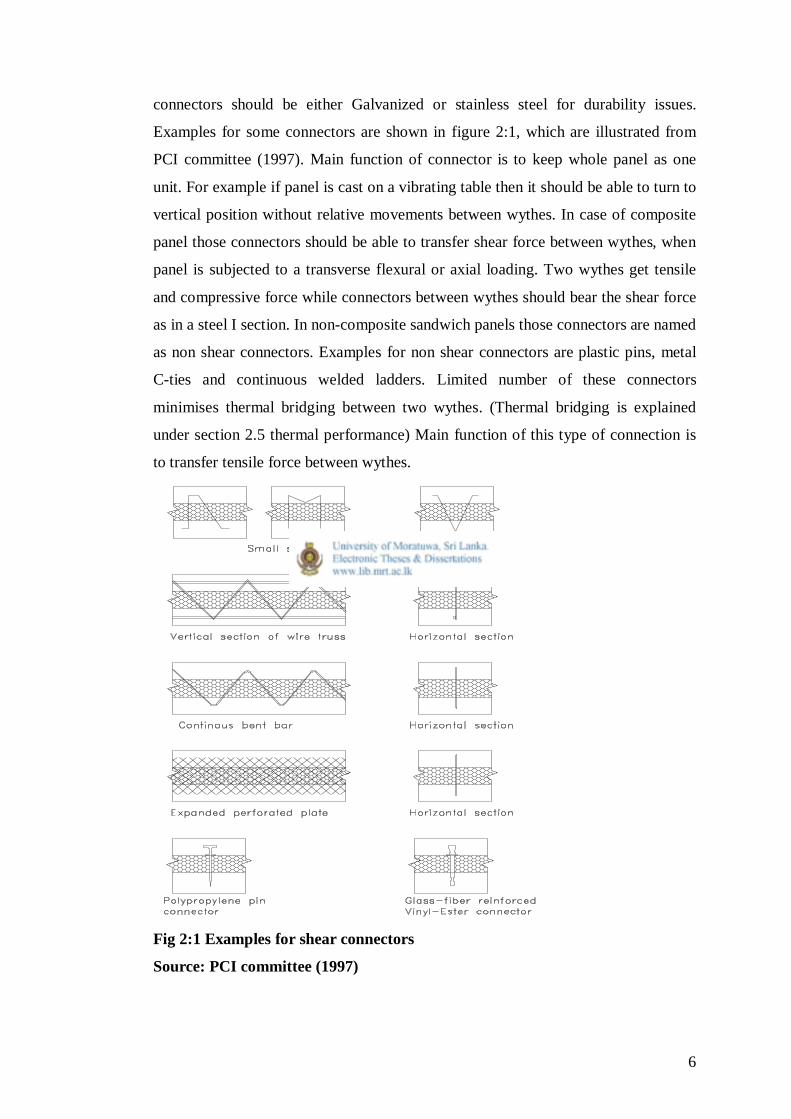
connectors should be either Galvanized or stainless steel for durability issues.
Examples for some connectors are shown in figure 2:1, which are illustrated from
PCI committee (1997). Main function of connector is to keep whole panel as one
unit. For example if panel is cast on a vibrating table then it should be able to turn to
vertical position without relative movements between wythes. In case of composite
panel those connectors should be able to transfer shear force between wythes, when
panel is subjected to a transverse flexural or axial loading. Two wythes get tensile
and compressive force while connectors between wythes should bear the shear force
as in a steel I section. In non-composite sandwich panels those connectors are named
as non shear connectors. Examples for non shear connectors are plastic pins, metal
C-ties and continuous welded ladders. Limited number of these connectors
minimises thermal bridging between two wythes. (Thermal bridging is explained
under section 2.5 thermal performance) Main function of this type of connection is
to transfer tensile force between wythes.
Fig 2:1 Examples for shear connectors
Source: PCI committee (1997)

7
2.2.3 Insulation
Insulation is the most vulnerable part of SWP when considering durability and
strength aspects. Positioning this weak insulation layer in between two durable and
hard concrete wythes provides the best structural insulation system. Therefore, this
insulating technique provides low maintenance, durable, fire resistant and highest R-
value (Thermal resistance) per unit cost.
Although there are many insulation types on the market today, insulated concrete
sandwich walls utilize a cellular (rigid) insulation because it provides those material
properties that are most compatible with concrete. These compatible material
properties include moisture absorption, dimensional stability, coefficient of thermal
expansion, compressive and flexural strengths. Selection of the type of insulation to
enhance energy performance is as important as the reinforcement needed to enhance
structural performance. Insulation selection can affect the longevity of panel’s
intended effectiveness depending on site location, climate variables and operating
conditions.
Thermoplastic and thermosetting are the two primary forms of cellular insulation
used in the manufacture of sandwich panels. The thermoplastic insulations are better
known as moulded expanded Polystyrene (bead board) and extruded expanded
Polystyrene (extruded board). Thermosetting insulations consist of Polyurethane,
Polyisocyanurate and Phenolic. Physical properties are listed in Table 2.1 which is
published on PCI Committee (1997).

8
Table 2.1 Physical properties of insulation material Physical Polystyrene Polyisocyanurate
Phenolic
Cellular
Property Expanded Extruded Unfaced faced glass Density 11.2-
14.4 17.6-22.4 28.8 20.8-
25.6 28.8-35.2 48 32-96 32-96 32-48 107-147
kg/m3 Water
absorption <4.0 <3.0 <2.0 <0.3 <3.0 1.0-
2.0 <3.0 <0.5 (percent volume)
Compressive strength kPa
35-70
90-103 172 103-
172 276-414 690 110-345 110 70-110 65
Tensile strength kPa 124-172 172 345 724 310-965 3448 414 345
Linear coefficient
of expansion 10-6
mm/mm/0c
45-72 45-72 54-108 18-36 2.9-8.3
Shear strength kPa 138-241 - 241 482 138-690 83 345
Flexural strength kPa
69-172
207-276 345 276-
345 414-517 695 345-
1448 276-345 172 414
Thermal conductivity Wm/m2/C
0.043 0.037 0.033 0.029 0.026 0.014-
0.022 0.023-0.033 0.05
Maximum use
temperature 710C 710C 1180C 1460C 4800C
Source: PCI committee (1997)
ASTM C-578, ASTM C-591 and ASTM C-1126 are codes which specify above
mentioned insulation material production in United States. A concrete sandwich
panel is a unique environment for an insulating material. During manufacture of
panel the insulation is exposed to high temperatures from hydration and applied heat
from accelerated curing by steam. Insulation should also bear compressive load from
weight of upper concrete wythe plus foot traffic during production and high
moisture levels from curing of plasticized mix. Therefore, insulation should have
some compressive, flexural and shear resistance as mechanical properties and water
absorption and thermal conductivity as material properties to withstand those

9
production stage conditions. For example Polystyrene should not be used as
insulation when cured by steam curing which will melt after 710C.
In service condition, insulation is exposed to continuous moisture and vapour drive
that continues to affect the insulating material. Where temperature decreases below
zero 0C, freeze-thaw cycles occur daily just before and after winter. During those
periods temperature at night drops below 0 0C and during day time it increases
above zero with sun light. If moulded Polystyrene insulation which has a high
moisture absorption rating is used, a building with high moisture drive will cause
this insulation to absorb potentially large amount of moisture. When this is exposed
to freeze-thaw cycle, weak bond between the beads or cells of the insulation breaks
down and the insulation begins to disintegrate. This process can be mitigated by
choosing extruded polystyrene.
2.2.4 Steel reinforcements for wythes
Normal tore steel, mild steel or shop fabricated wire mesh having higher steel
diameter bars are used to produce precast concrete panels. Portland cement mortar
applied sandwich panels which are smaller in thickness always comes as Galvanized
Iron gauge 14 wire mesh. Explanation of using GI is to minimize corrosions in steel,
because mortar which has more voids ratio than concrete that allows Oxygen and
moisture movement into wythes and tends to corrode reinforcements quickly. Report
of Chandrasena (2010) had shown this corrosion effect from his experimental
investigations.
2.3 Precast panel sizes
Precast panel width and length vary according to the requirement of application. For
example storey height for SWP span between ground and beam or length between
adjacent columns for SWP span between columns in horizontal direction. Maximum
size generally depends on casting vibration table size and transportation restrictions.
Erection cranes’ capacity and the crane approach distance also govern the size of
precast sandwich wall size. In such case, if wall height is fixed, weight may adjust
by the width of wall. Then the number of pieces may increase.

10
2.4 Bowing in sandwich wall panels
This is a major disadvantage of SWP. Due to differential expansion or contraction in
two wythes the wall panel tends to bowing. This differential expansion may be due
to the following factors;
(1) Thermal gradient across wall thickness
(2) Differential humidity causing differential wythe shrinkage
(3) Differential modulus of elasticity between wythes
These actions cause a wythe to lengthen or shorten than the other. When SWP is
composite i.e. wythe connectors can bear overall shear force between wythes, SWP
tends to bowing. Therefore, bowing is also a function of the degree of
compositeness.
According to PCI committee (1997), this bowing cannot be estimated accurately due
to uncertainty in material properties, actual thermal gradient, restraints provided by
supports and compositeness. But they had given some approximate methods to
calculate bowing based on experience.
2.5 Thermal performance
Parallel to the development of sandwich walls by the concrete industry is urgency in
the industry to develop procedures to calculate the actual performance
characteristics of building envelopes. Buildings’ energy performance is manifested
in the ASHRAE standard published in cooperation with the Department of Energy
and the Environmental protection Agency United States. This standard sets strict
compliance guidelines for building design and calculation of performance for the
entire constructed facility. Three national codes of United States: BOCA, SSBCI and
ICBO had adopted those requirements in them.
Thermal transmission is usually the most important physical property for the
insulation in a concrete sandwich wall. The ability to resist energy flow is affected

11
by the ability of the insulation system to resist the transfer of energy. In order to
construct an insulated panel assembly, wythe ties (shear connectors) must often pass
through the insulation layer. This construction practice interrupts the otherwise
continuous insulation layer and thus, provides the potential for conduction of
thermal energy. These interruptions are known as “thermal bridges”. They can be
steel, concrete, composites or plastics. A thermal bridge conducts energy at a much
higher rate than the insulation, thus creating short circuits where they occur. This
short circuit thermal bridge reduces the effectiveness of the insulation.
ASHRAE standard addresses the calculation of the thermal bridge by mandating the
use of two calculation methods;
(1) Isothermal (series –parallel) analysis
(2) Zonel method analysis
Recent developments in insulation system industry has minimized or eliminated the
solid zones of concrete or steel connectors or both. The selection of the insulation
system for use in the SWP should be based on the conditions in the building
environment, the required structural performance and the effect that the building
codes have on the construction assembly.
2.6 Composite and non-composite behaviour of sandwich wall panel
Fig 2.2: Non composite and fully composite panels’ theoretical behaviour
Source: Benayoune et al. (2006)
12
In non composite panel under flexure, each wythe deflects independently.
Connectors between them only maintain gap between two wythes. Stress or strain
distribution along panel thickness is shown in figure 2.2 upper diagram.
Fully composite panel which has shear transfer mechanism deflects as in lower part
of the figure and stress or strain distribution along panel thickness is also shown.
Truss connectors which can bear compressive and tensile forces exhibit nearly
composite behaviour in SWPs. The paper Benayoune, Abdul, Samad, Trikha, Ali &
Ellinna (2006) had discussed this area and shown all SWPs are in between fully
composite and non composite regions.
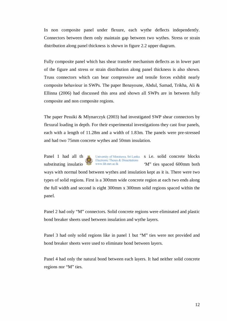
The paper Pessiki & Mlynarczyk (2003) had investigated SWP shear connectors by
flexural loading in depth. For their experimental investigations they cast four panels,
each with a length of 11.28m and a width of 1.83m. The panels were pre-stressed
and had two 75mm concrete wythes and 50mm insulation.
Panel 1 had all three types of shear connections i.e. solid concrete blocks
substituting insulation between wythes, mechanical “M” ties spaced 600mm both
ways with normal bond between wythes and insulation kept as it is. There were two
types of solid regions. First is a 300mm wide concrete region at each two ends along
the full width and second is eight 300mm x 300mm solid regions spaced within the
panel.
Panel 2 had only “M” connectors. Solid concrete regions were eliminated and plastic
bond breaker sheets used between insulation and wythe layers.
Panel 3 had only solid regions like in panel 1 but “M” ties were not provided and
bond breaker sheets were used to eliminate bond between layers.
Panel 4 had only the natural bond between each layers. It had neither solid concrete
regions nor “M” ties.

13
They investigated panels’ compositeness in non cracked state. For panel 1 it was
100% (fully) composite, panel 2 of “M” ties only 10%, panel 3 solid concrete
regions 92% and panel 4 of bond only 5%. They proposed to have more solid
regions when compositeness is important.
2.7 Axial load bearing capacity
SWP function as efficiently as solid wall panels but differ in their build up. Interest
in SWP as load bearing wall panels has been growing over recent past because
manufacturers are looking for more viable products and architects and engineers are
pleased with the structural and energy performance of the SWP.
SWPs acting as load bearing elements are structurally efficient and eliminate the
need of beam and columns. At the same time economical means of foundation can
be built due to elimination of point loads from columns. SWPs when used for load
bearing purpose, they should be able to resist various loads such as;
1. Self weight
2. Roof and floor slabs dead and imposed load
3. Wind
4. Seismic
5. Load from adjacent panels
6. Temperature
7. Differential shrinkage between wythes (PCI Committee 1997)
The paper by Benayoune, Samad, Ali & Trikha (2005a) had investigated axial load
bearing capacity of precast concrete sandwich wall panels.
Most research and papers were published on flexural and shear capacity of SWP.
But very few papers found on axial capacity. Therefore, this paper Benayoune et al.
(2005a) provides better description on precast concrete sandwich wall panels under
axial loading.
This paper presented load bearing capacity of solid concrete walls by empirical
equations by different researches. They are presented below;

14
1. Leabu, V.F., Problems and performance of precast concrete walls. (As cited in
Benayoune et al., 2005a)
Pu= 0.2 fcu Ac [1- (H/40t)3]
Where Pu ultimate axial load, Ac gross area of wall, fc characteristic cube strength of
concrete, H effective height and t thickness of wall.
2. Oberlender, G.D., Everard N.J., Investigation of reinforced concrete wall panels.
(As cited in Benayoune et al., 2005a)
Pu= 0.6 fcu Ac [1- (kH/30t)2]
Where Pu ultimate axial load, Ac gross area of wall, fc characteristic cube strength of
concrete, H effective height and t thickness of wall. k is 0.8 for walls restrained
against rotation and 1.0 for unrestrained against rotation.
3. Pillai S.U., Parthasarathy C.V., Ultimate strength and design of concrete walls,
(As cited in Benayoune et al., 2005a) expressed a formula. They considered earlier
variables plus reinforcement percentage for their study. They found that steel
reinforcements’ influence is very less to ultimate axial capacity. They also found
walls having H/t ratio higher than 20 failed by buckling and lower in crushing. For
H/t less than 30
Pu= 0.57 Ffcu Ac [1- (kH/50t)2] where F=0.7 for compression members.
4. Kripanarayanan K.M., Interesting aspect of the empirical wall design equation,
(As cited in Benayoune et al., 2005a) found steel reinforcement percentage in order
of 0.75-1.0% of the wall cross section area has significant increase in wall capacity.
He also found minimum reinforcement percentage specified (0.25%) didn’t increase
wall capacity. Therefore, his formula also not included reinforcement contribution.
His formula is
Pu= 0.55 Ffcu Ac [1- (kH/32t)2]
ACI code specifies above formula where walls restrained at top and bottom with H/t
≤25 or L/t ≤ 25, whichever is less for load bearing walls, Where L is wall width.
15
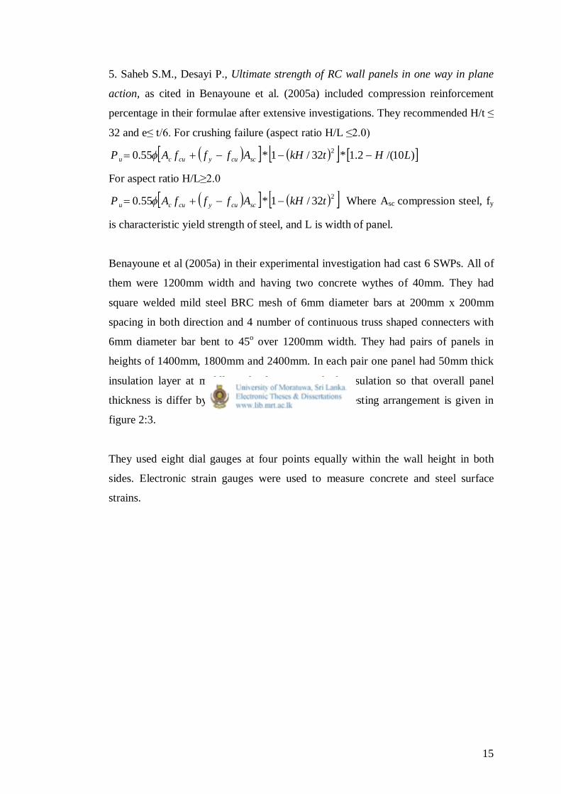
5. Saheb S.M., Desayi P., Ultimate strength of RC wall panels in one way in plane
action, as cited in Benayoune et al. (2005a) included compression reinforcement
percentage in their formulae after extensive investigations. They recommended H/t ≤
32 and e≤ t/6. For crushing failure (aspect ratio H/L ≤2.0)
)10/(2.1*32/1*55.0 2 LHtkHAfffAP sccuycucu
For aspect ratio H/L≥2.0
232/1*55.0 tkHAfffAP sccuycucu Where Asc compression steel, fy
is characteristic yield strength of steel, and L is width of panel.
Benayoune et al (2005a) in their experimental investigation had cast 6 SWPs. All of
them were 1200mm width and having two concrete wythes of 40mm. They had
square welded mild steel BRC mesh of 6mm diameter bars at 200mm x 200mm
spacing in both direction and 4 number of continuous truss shaped connecters with
6mm diameter bar bent to 45o over 1200mm width. They had pairs of panels in
heights of 1400mm, 1800mm and 2400mm. In each pair one panel had 50mm thick
insulation layer at middle and other 40mm thick insulation so that overall panel
thickness is differ by 10mm. Sketch of their panel testing arrangement is given in
figure 2:3.
They used eight dial gauges at four points equally within the wall height in both
sides. Electronic strain gauges were used to measure concrete and steel surface
strains.

16
Fig 2.3 Test set-up and test frame of Benayoune et al. (2005a)
They found that a panel with 40mm insulation and 2400mm height, which is most
slender, laterally deflected more than that of 1400mm panel having 50mm
insulation. When considering two 2400mm wall panels, 40mm insulation panel
laterally deflected more than that of 50mm insulation one. But their difference is
much low. 2400mm wall panel when subjected to axial load, most deflection shown
in the dial gauges located at top most position (not at mid height). They also found
that the readings from each two dial gauges in equal height given same magnitude of
reading but opposite direction. Therefore, they assumed wall panels behaved
compositely until failure.

17
The paper also discussed strain results with loading. According to the results shown,
2400mm height panel with 40mm insulation (maximum slenderness H/t=20) had
beard 985kN/m minimum ultimate axial load. On the other hand, 1400mm panel
which had minimum slenderness of 10.8 had maximum ultimate axial load of
1187kN/m. Although slenderness nearly doubled, failure load varied only 17%. Also
concrete crushing failure had observed near top and bottom supports.
They had a finite element model for precast concrete sandwich panel. They used
commercially available finite element software called LUSAS. They did not model
whole panel but simplified it to a system with one truss and equivalent width of
300mm concrete wythes. They modelled concrete wythe as 2-D isoparametric plane
stress elements, having two degrees of freedom at each node and steel
reinforcements and truss elements as 2-D isoparametric bar element, having two
degrees of freedom at each node. Movement perpendicular to the plane had not been
considered. Support condition at bottom of the panel assigned as fixed while top as
pin. Both material and geometric non linearity were considered in the analysis.
Newton-Raphson procedure based non-linear solution had been used. To invoke
large displacement effects, total Lagragian formulation had been taken.
Benayoune et al (2005a) proposed an empirical equation considering test results and
finite element modelling. i.e. scyccuu AftkHAfP 67.040/14.0 2
Where Ac is the gross area of the wall panel section (assume equal to the gross
concrete area); Asc the area of compression steel; fcu the characteristics strength of
concrete; fy the characteristic yield strength of steel; t the thickness of the panel
section; H the effective height; and K the constant 0.8 for wall restrained against
rotation, 1 for walls unrestrained against rotation.
Further limitations were defined to use this formula.
1. The panel act in a fully composite manner
2. The load on the panel is reasonably concentric, i.e. the resultant must be in
the middle third of overall thickness of the wall. This allows maximum
eccentricity of t/6.
3. The slenderness is limited to 25.

18
Benayoune et al had investigated precast sandwich wall panels in eccentric axial
load (Benayoune,Aziz, Samad, Trikha, Ali & Ashrabov 2005b).
They had cast 12 precast SWPs. In this 12 panels had two identical elements in each.
Therefore, one set had 6 panels and the other had 6. The first set was tested without
eccentricity and the other with eccentricity. Those 6 panels each had 3 heights of
1400mm, 1800mm and 2400mm. Then each height was subdivided again into two
by varying insulation thickness of 40mm and 50mm. Therefore, overall thicknesses
were 120mm and 130mm. Results of axially loaded panels were not given in the
paper.
Panel reinforcements, trusses and test procedure were same as in earlier paper
(Benayoune et al., 2005a). The only difference was assigning eccentricity. Here they
had inserted 20mm x 20mm flat Iron between spreader beam and SWP as shown
fig.2.4.
Eccentricity
Fig 2:4 Top end condition and loading arrangement of Benayoune et al. (2005b)

19
They had used 40mm eccentricity for all panels tested in eccentric axial load.
Maximum thickness of a panel was 130mm. Therefore, eccentricity equals to
21.67mm (130mm /6). Thus test panels were subjected to an eccentricity more than
that of minimum specified for pure axial compressive loading.
According to their experimental ultimate eccentric axial loads, they found maximum
of 857kN/m for 1400mm panel with 130mm thickness and minimum of 624kN/m
for 2400mm panel with 120mm thickness. Those results are closer to previous axial
load results but relatively lower than them. That means that when slenderness vary
from 10 to 20, results dropped by 37%.
Their finite element model which was similar to previous paper (Benayoune 2005a)
had given them closer results in ultimate eccentric axial loading. In this experiment
they also found 2400mm high panel has got maximum deflection at a dial gauge of
300mm below from the top end (not in mid height).
They also used classical expressions based on reinforced concrete principles to
investigate ultimate axial load, but the calculated theoretical values assuming fully
composite behaviour for panels were far less than experimental and FEM results.
BOCA (1999) provides guidelines to estimate load bearing capacity of SWPs with
100mm insulation and 25mm structural wythes out of cement mortar. Figure 2.5
illustrates specified sandwich wall panel.

20
12,5 12,5 100 12,5 12,5
125150
Fig 2.5 The Artzer panel specified by BOCA (1999)
According to the above report, the panel can bear following axial loads without
applied moment as given in table 2.2.
Table 2.2 Allowable axial load
Panel Height (mm) Allowable Axial Loads (kN/m)
2400 105
4800 80
6600 50
Source: BOCA (1999)
The specifications given to above table;
1. Values based on lesser of the calculated value, the ultimate load divide by
2.5 or the load at a deflection of L/240, where L equals the unsupported span
of panel.
2. Spans and load shall not be interpolated.
21
3. For combination of axial and transverse loading the following formula shall
apply. 0.1B
b
A
a
WW
PP
where aP = Calculated design axial load
AP =Allowable axial load
bW = Calculated design transverse load
BW = Allowable transverse load
4. Values are concentric axial compressive loads. Other axial loading
conditions are beyond the scope of the report.
5. The fire resistance rated assembly described in this report is limited to a
maximum height of 2700mm and a maximum concentric axial compressive
load of 17kN/m.
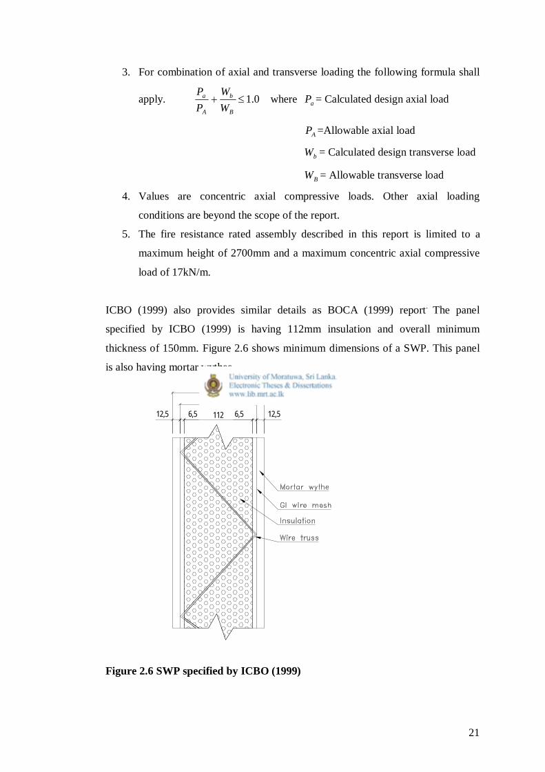
ICBO (1999) also provides similar details as BOCA (1999) report. The panel
specified by ICBO (1999) is having 112mm insulation and overall minimum
thickness of 150mm. Figure 2.6 shows minimum dimensions of a SWP. This panel
is also having mortar wythes.
12,5 6,5 112 6,5 12,5
125150
Figure 2.6 SWP specified by ICBO (1999)

22
Table 2.3 provides axial load bearing capacity with relative to wall height, which
was taken from ICBO (1999) report.
Table 2.3 Allowable axial load
Panel Height (mm) Allowable Axial Loads (kN/m)
2400 43.8
3600 41.3
4800 38.7
6600 24.8
Source: ICBO (1999)
Their limitations are also same as BOCA (1999) report for axial loading.
Chandrasena (2010) had tested standard KIO panel in size of 900mm height 900mm
width and 100mm overall thickness in axial loading. This KIO panel section is
shown in fig 2.7.
12,5 12,5 50 12,5 12,5
75
Figure 2.7 Standard KIO panel section
According to the report, 900mm high panel had an ultimate axial load capacity of
15.4 kN/m.
Similar sandwich wall panels produced by Micro constructions limited were tested
at University of Moratuwa structural engineering laboratory on 23rd of November

23
2010. The report “Test on 3D insulated Micro Panels for compression and flexural
strengths” (Micro, 2010) provides experimental investigations from testing
programme. Three panels of 1200mm width 2400mm height and in two different
insulations were tested in axial compression. Panels were named as A,B and C.
Panel A had 100mm insulation and nearly 25mm thick cement mortar on both sides
to form 160mm overall thickness. Panels B and C had 50mm insulation layer and
overall thicknesses of 105mm and 110mm. In micro panel, continuous separate wire
trusses were not present but had gauge 9 GI wire angular rods welded to two square
meshes at each side in regular interval of 100mm both ways. Figure 2.8 illustrates
the module of the panel.
12,5 12,5 50 12,5 12,575100
Fig 2.8 50mm insulated Micro Construction SWP
Panel A had an ultimate axial compressive load of 235.2kN/m and failed by spalling
of plaster at the top end. Panel B had an ultimate axial load of 199.9kN/m. Panel C
had an ultimate load of 147.5kN/m and separation of plaster layer had been
observed.
24
2.8 Flexural loading capacity of SWP
Much more research has taken place to investigate flexural capacity than axial
compression for the system. Investigation in flexural strength is important in SWP
because even non load bearing (partitioning only) type SWPs should bear transverse
loading such as wind, seismic and soil pressure. The role of shear connecters and its
behaviour can also be investigated better in such tests.
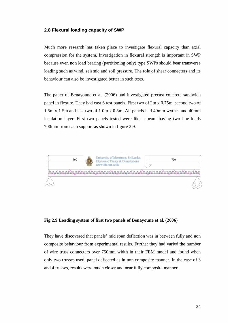
The paper of Benayoune et al. (2006) had investigated precast concrete sandwich
panel in flexure. They had cast 6 test panels. First two of 2m x 0.75m, second two of
1.5m x 1.5m and last two of 1.0m x 0.5m. All panels had 40mm wythes and 40mm
insulation layer. First two panels tested were like a beam having two line loads
700mm from each support as shown in figure 2.9.
700 700
2000
Fig 2.9 Loading system of first two panels of Benayoune et al. (2006)
They have discovered that panels’ mid span deflection was in between fully and non
composite behaviour from experimental results. Further they had varied the number
of wire truss connecters over 750mm width in their FEM model and found when
only two trusses used, panel deflected as in non composite manner. In the case of 3
and 4 trusses, results were much closer and near fully composite manner.
25
A paper published on Precast/Prestressed concrete institute (PCI) journal under
heading “Flexural Behaviour of composite Precast concrete sandwich panels with
continuous truss connectors” (Bush & Stine, 1994) have also studied in this area.
They also tested SWPs which are pre-stressed concrete, under uniform distributed
transverse load without axial stress.
They had cast two sets of panels. One series was commercially manufactured type
and other was modified series. The production series had 4 number of 300mm x
300mm size concrete web between two wythes which substitute insulation and used
to place lifting inserts. In modified series they had some other mechanism to lift
panel which had continuous insulation throughout. They had done three varieties of
tests. First set was static flexural loading, second was push-out test and third was
fatigue flexural loading. In push-out test they tried to investigate members of wire
truss behaviour when one wythe is displaced relative to other. Fatigue load test was
done by using servo-controlled hydraulic actuator with spreader beam with three
points loading. Their static flexural test investigations are important when
considering failure modes of truss connectors.
All SWPs had two 75mm wythe layers and 50mm insulation layer and 4.8m span.
They found commercially manufactured type SWPs behave near composite even
without truss connectors, because solid concrete zone in between wythes transfer
most of the shear. Further modified series SWPs which had 3 wire trusses
distributed along the width of panel failed in a higher applied UDL than other with
less number of trusses. Same series SWP with two truss girders failed in classical
flexural cracking in tension. At the load of 14.4 kPa yielding and buckling of truss’
diagonal members had occurred in the ends of panel. Then after redistribution of
stress, quarter span diagonal members experienced the same in load of 15.5kPa.
Einea, Salmon, Tadros & Culp (1994) had tested precast sandwich wall panels with
FRP shear connector system between wythes. The new material is thermally
efficient than steel. Steel creates thermal bridges between wythes. Their findings
were discussed in a paper named “A new structurally and thermally efficient precast

26
sandwich panel system”. They had done several experiment series. Their flexural
test with trusses in FRP diagonal members to investigate composite behaviour is
relevant to current SWP. Two SWPs with 63mm wythes and 75mm insulation in
FRP truss connectors were cast. First one had bond breaker sheets in between
concrete and wythes. Second one did not have those. 2.4m precast panels placed
horizontally in two roller supports at ends and given two point loading using a steel
frame. They measured both central deflection and applied force. Analysing test
results they found, that the first panel had 65% fully composite SWP ultimate
strength and second had 81% of that. They used electronic strain gauges to measure
strain in each diagonal member. They found some FRP members had buckled when
panel was subjected to two points loading. Even though FRP is a brittle material
which has sudden failure mode, test panels had shown ductile failure which exhibit
much cracking and higher deformation prior to failure.
According to BOCA (1999) the SWP as described earlier (mortar wythes) can bear
safe transverse UDL as in following table 2.4.
Table 2.4 Allowable transverse loads
Unsupported span (mm) Allowable Wind Load (kN/m2)
2400 5.64
3600 2.49
4800 1.39
6600 0.76
Source: BOCA (1999)
The values were taken as minimum of either dividing ultimate load values by 2.5 or
the load cause to deflection of the span divided by 240.
Similar transverse load table appeared in ICBO (1999) but specified loads are much
less than of BOCA (1999). Its allowable loads relative to wall span are shown below
in table 2.5.
27
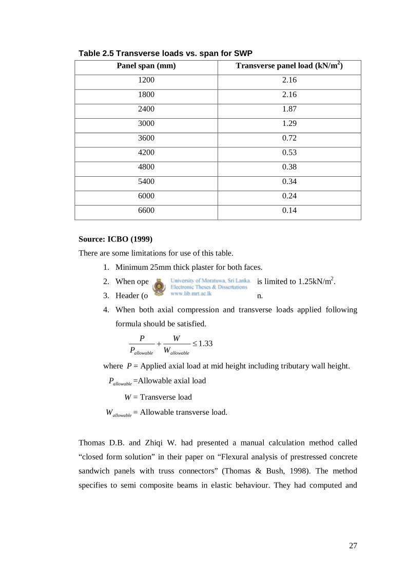
Table 2.5 Transverse loads vs. span for SWP Panel span (mm) Transverse panel load (kN/m2)
1200 2.16
1800 2.16
2400 1.87
3000 1.29
3600 0.72
4200 0.53
4800 0.38
5400 0.34
6000 0.24
6600 0.14
Source: ICBO (1999)
There are some limitations for use of this table.
1. Minimum 25mm thick plaster for both faces.
2. When opening is in a wall, transverse load is limited to 1.25kN/m2.
3. Header (or lintel depth) is 450mm minimum.
4. When both axial compression and transverse loads applied following
formula should be satisfied.
33.1allowableallowable WW
PP
where P = Applied axial load at mid height including tributary wall height.
allowableP =Allowable axial load
W = Transverse load
allowableW = Allowable transverse load.
Thomas D.B. and Zhiqi W. had presented a manual calculation method called
“closed form solution” in their paper on “Flexural analysis of prestressed concrete
sandwich panels with truss connectors” (Thomas & Bush, 1998). The method
specifies to semi composite beams in elastic behaviour. They had computed and

28
compared closed form method solution with FEM results and test data taken from
earlier test series.
Their findings are briefed under.
1. Closed form theory, modified to account for truss connectors, predicted
maximum deflections and bending stresses in close agreement with FEM
models.
2. Closed form and FEM results for panel deflection and stresses produced
were reasonable but conservative compared to experimental data.
3. For truss forces which were substantially over predicted need a correction to
reach close agreement with experimental data. Apparently, there were
additional shear transfer mechanisms present in the test panels that were not
captured in FEM, for example lifting inserts.
4. Substantial degree of composite action is indicated by trusses in the analysis.
For given amount of reinforcements, longer panels behave more composite
than shorter panels.
Therefore, above paper provides a better tool to understand flexural behaviour of
SWP especially when it is bearing eccentric loading.
2.9 Summary
Mainly there are two types of SWP systems. First is with concrete wythes and
second with mortar wythes. Concrete wythes minimum thickness is 50mm and that
of mortar is 18mm. Some literature came cross are relevant to concrete SWPs and
other to mortar SWPs. The literature had discovered different aspects of SWP
systems for example axial load bearing capacity, flexural loading capacity,
compositeness, etc. The samples of current research are more relevant to ICBO
(1999) and BOCA (1999). Because they specifies SWP with mortar wythes. Other
literature is also important to identify failure modes of complicate SWP system.
Further investigation is needed for locally available SWPs, because there is no Sri
Lankan guideline to specify material quality and load bearing capacity. There is a

29
need to investigate load bearing reduction due to opening in a wall, which is lack in
the literature.
Experimental procedure of this report aims to fill some gap mentioned above by
conducting laboratory test of actual SWPs. Panel casting and laboratory testing are
discussed in Chapter 3.

30
Chapter 3
Experimental Study
3.1 General Introduction
Micro Constructions is the leading producer of SWPs in Sri Lanka. Micro Constructions
produces two types of SWPs. One is with 50mm EPS insulation and other is 100mm
EPS insulation. Fig 2.8 illustrates 50mm insulated Micro Construction SWP. EPS with
two gauge 12 nets with welded truss connectors are imported from India. There are two
outer mortar layers of approximately 25mm thick. This type is having minimum overall
wall thickness of 100mm. The other type is having minimum wall thickness of 150mm.
They had cast test specimens for the research at their Dehiwala construction site. For
this research only 50mm insulated SWPs were used. Three panels of 1200mm width
2400mm high and 100mm thick were cast. Out of these three panels two panels had
600mm width and 900mm height opening shown in fig 3.1. Remaining panel was a full
panel i.e. without opening. Those three specimens were used to test on axial
compression.
Another six numbers of 600mm width and 300mm height blocks of same panel type
were cast. Three blocks were used to get compression capacity and other three were
used to get flexural capacity.
Six numbers of 150mm cubes were cast to get compression capacity of mortar.

31
Fig 3.1 Dimensions of test panels with opening
3.2 Equipments used to produce SWP
3.2.1 Cement mortar sprayer
Micro Constructions uses mortar spraying system to apply two mortar layers. Method is
similar to paint spraying gun. Here mortar is poured to the hopper and compressed air is
blown through four nozzles located at the bottom of the hopper. There are four holes
directly opposite to nozzles in bottom outer surface of the hopper. When air is blown
under high pressure, stagnated mortar in between nozzles and holes is thrown away fast.
Mortar on top is fallen down under gravity to fill the void and process continues until
mortar in the hopper is empty. Figure 3.2 shows photograph of the mortar sprayer.
Figure 3.3 shows the nozzles located at the bottom of the hopper.
600
1200
900
2400
300 300
300
1200

32
Fig. 3.2 Mortar sprayer
Fig. 3.3 Four nozzles at bottom

33
3.2.2 Pair of pliers
Pair of pliers (cutting) is used to cut GI wire mesh and trusses of the panel.
Fig 3.4 Pair of pliers
3.2.3 Pneumatic “c” ring gun
C rings are used to tie reinforcements in this system. It is a fast and easy method of
tying. C ring cartridge is feed to pneumatic operated gun. Figures 3.5 and 3.6 shows
both C ring cartridge and the gun
Fig 3.5 “C” ring cartridge

34
Fig 3.6 Pneumatic C ring gun
3.2.4 Air compressor
Air compressor is used to supply high pressure air to both mortar sprayer and C ring gun.
Fig 3.7 Air compressor

35
3.3 Panel casting
Initially two panels which had openings were marked using tape and marker pen. (Fig
3.8) Then GI wire meshes were cut by pliers. After that EPS layer was cut by hacksaw
blade. (Fig 3.9)
Fig 3.8 Marking the opening
Fig 3.9 Cutting EPS layer by hacksaw

36
Then additional nets were cut and bent to the shape required. Then the nets were placed
and tied using C ring gun. (Fig 3.10) 400mm x 200mm gauge 12 nets used at corners
diagonally as additional reinforcements.
Fig 3.10 Reinforcements tying using C ring gun
Micro construction uses fine sand for their mortar mixture. The mortar was mixed using
concrete mixer. They have their own cement, sand and water mixture proportions,
which is consistent to them. Otherwise mortar cannot be sprayed using the sprayer.
For this precast sample panels casting, they sprayed mortar in four stages.
1. Single side was sprayed and levelled roughly to gauge 12 net. (Fig 3.11)
2. After hardening it for one day other sides’ first mortar layer was sprayed and
levelled.
3. After another minimum period of one day first sides’ final mortar layer was
placed (third layer). For this basic plastering system is used including placing
levelling pegs at even intervals. Fig 3.12.
4. Final plastering layer was placed as above after third step. Mortar was sprayed
using same sprayer.

37
When Micro uses in situ system of casting, they follow only two steps. i.e. plaster both
first layer at one stage up to gauge 12 net level and after hardening two final layers at
once. This is quicker than precast option.
Fig 3.11 First plaster layer levelling
Fig 3.12 Plastering third mortar layer of the wall
38
After that they finish plastering around openings and edges. This method was followed
for all three full panels and 300mm x 600mm blocks casting.
All elements cured using water for 7 days. They were transported to University of
Moratuwa using a boom truck after 21 days.
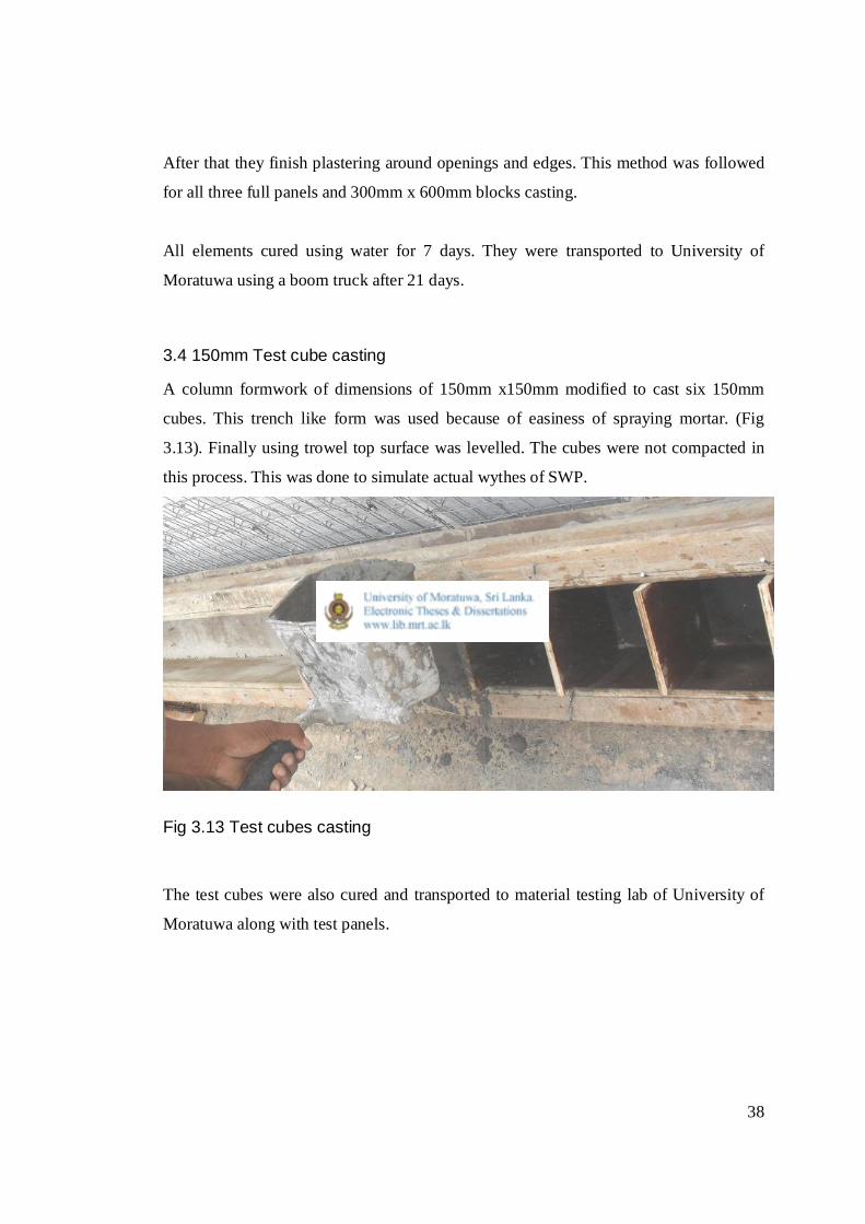
3.4 150mm Test cube casting
A column formwork of dimensions of 150mm x150mm modified to cast six 150mm
cubes. This trench like form was used because of easiness of spraying mortar. (Fig
3.13). Finally using trowel top surface was levelled. The cubes were not compacted in
this process. This was done to simulate actual wythes of SWP.
Fig 3.13 Test cubes casting
The test cubes were also cured and transported to material testing lab of University of
Moratuwa along with test panels.

39
3.5 Testing panels under axial compression load
Initially full panel without opening which marked as “A” was setup under the steel
frame. Then overall dimensions and thickness were measured.
Fig. 3.14 Test setup
After fixing transverse supports at the top of panel, verticality was checked using plum
bob and necessary adjustments were done by moving bottom of the panel. Then
spreader beam, hydraulic jack and proving ring were placed as in figure 3.14. Further,
two 50mm x50mm timber pieces were placed either side of the panel with a gap for

40
additional safety. A dial gauge was placed at the mid height of the panel to measure any
lateral deformations.
After setting up the panel, mid height dial gauge reading was measured against the
proving rings’ dial gauge reading. This had done by gradually applying axial force
using hydraulic jack. Those readings were recorded until the panels’ failure.
Fig 3.15 Test setup of panels with opening
41
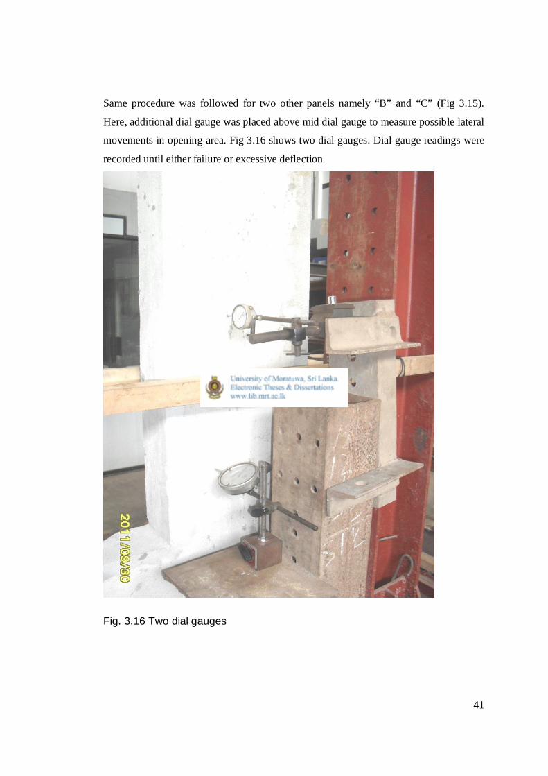
Same procedure was followed for two other panels namely “B” and “C” (Fig 3.15).
Here, additional dial gauge was placed above mid dial gauge to measure possible lateral
movements in opening area. Fig 3.16 shows two dial gauges. Dial gauge readings were
recorded until either failure or excessive deflection.
Fig. 3.16 Two dial gauges

42
3.6 Testing small SWP blocks for compression
Fig 3.17 600mm x 100mm x 300mm blocks testing
Blocks’ actual dimensions were measured and recorded. Three blocks were tested as
shown in figure 3.17 in a universal testing machine. Ultimate axial load capacities were
recorded for each block.

43
3.7 Testing mortar test cubes for compression
Initially mortar test cubes dimensions and weights were measured. Then all six mortar
cubes were tested in universal testing machine.
3.8 Testing gauge 9 GI wire diagonal members in compression
The diagonal members of truss elements of SWP were cut from actual panel. The three
wire samples had average length of 100mm. These were tested in universal timber
testing machine under compression.
Sample 1 had 70kg compressive force and other two had that of 68 kg.
All test results with failure modes are presented with analysis in Chapter 4.

44
Chapter 4
Analysis and Discussion of Results
4.1 General Introduction
Axial compression load bearing capacity of SWPs’ experimental findings and estimated
axial load capacity according to literature are presented in this chapter. Their
compatibility is also discussed.
4.2 Experimental Results
4.2.1 Panel A
The panel without opening which named as Panel A is shown below in fig. 4.1. SWP
dimensions including thickness, horizontal support locations and dial gauge location
also mentioned in the diagram.
Fig. 4.1 Panel A

45
Panel A had a crack at one bottom corner when load was just 20kN and then the part
fully separated from the panel. When load around 80kN, local cracks at bottom support
were observed. Panel A had an ultimate axial load of 156.3 kN and 5.05mm maximum
central horizontal deflection. Severe local crushing failure at bottom up to a height of
150mm and top loading points were observed at ultimate condition. But couldn’t
observed any crack at mid height of the panel. Therefore panels’ failure was due to
crushing.
Ultimate load per metre run of panel A = 156.3 kN / 1.25m = 125 kN/m
Axial load vs. Central lateral deflection is shown under Fig 4.2.
0
20
40
60
80
100
120
140
160
0 1 2 3 4 5 6
Central Lateral Deflection (mm)
Axi
al L
oad
(kN
)
Fig 4.2 Axial Load vs. Central Lateral Deflection for Panel A

46
4.2.2 Panel B
First panel with opening which named as Panel B is shown below in fig. 4.3. SWP
dimensions including thickness, horizontal support locations and dial gauge location
also mentioned in the same diagram.
Fig. 4.3 Panel B
Panel B had an initial crack at top corner at horizontal restraint, when load was around
100kN. Then a horizontal crack of about 400mm observed 50mm from bottom.
Crushing failure occurred both bottom and top loading points. After the failure load
could not increased further. Panel B had an ultimate axial load of 159.7 kN and 4.4 mm
maximum central horizontal deflection.

47
Ultimate load per metre run of panel B = 159.7 kN / 1.25m = 127.8 kN/m
Axial Load vs. lateral deflections is shown under Fig 4.4.
0
20
40
60
80
100
120
140
160
180
0 0.5 1 1.5 2 2.5 3 3.5 4 4.5 5
Lateral Deflection (mm)
Axi
al L
oad
(kN
)
Dial Gauge ADial Gauge B
Fig 4.4 Axial Load vs. Lateral Deflection for Panel B
4.2.3 Panel C
Second panel with opening which named as Panel C is shown below in fig. 4.5. SWP
dimensions including thickness, horizontal support locations and dial gauge location
also mentioned in the diagram.
Panel C had its initial cracks when load is about 130kN at bottom of the panel. Diagonal
crack at top one side of panel and spalling of mortar from bottom end had seen after.
Panel C had to stop loading at axial load of 149.1 kN due to excessive central horizontal
deflection which was more than 25mm.
Ultimate load per metre run of panel C = 149.7 kN / 1.265m = 117.8 kN/m

48
Axial load vs. lateral deflections are shown in Fig 4.6.
Fig. 4.5 Panel C

49
0
20
40
60
80
100
120
140
160
0 5 10 15 20 25 30
Lateral Deflection (mm)
Axia
l Loa
d (k
N)Dial Gauge ADial gauge B
Fig. 4.6 Axial Load vs. Lateral Deflection for Panel C
4.2.4 600mm x 100mm x 300mm Blocks in axial compression
Three test blocks which were tested in universal testing machine had given following
results. All had crushing failure.
Table 4.1 Compression capacity of SWP blocks
NO
Cross section
Height (mm)
Failure Load (kN)
Ultimate Load (kN/m)
1 650x100 325 71.61 110.17
2 660x100 330 96.14 145.66
3 670x100 340 90.21 137.63
50
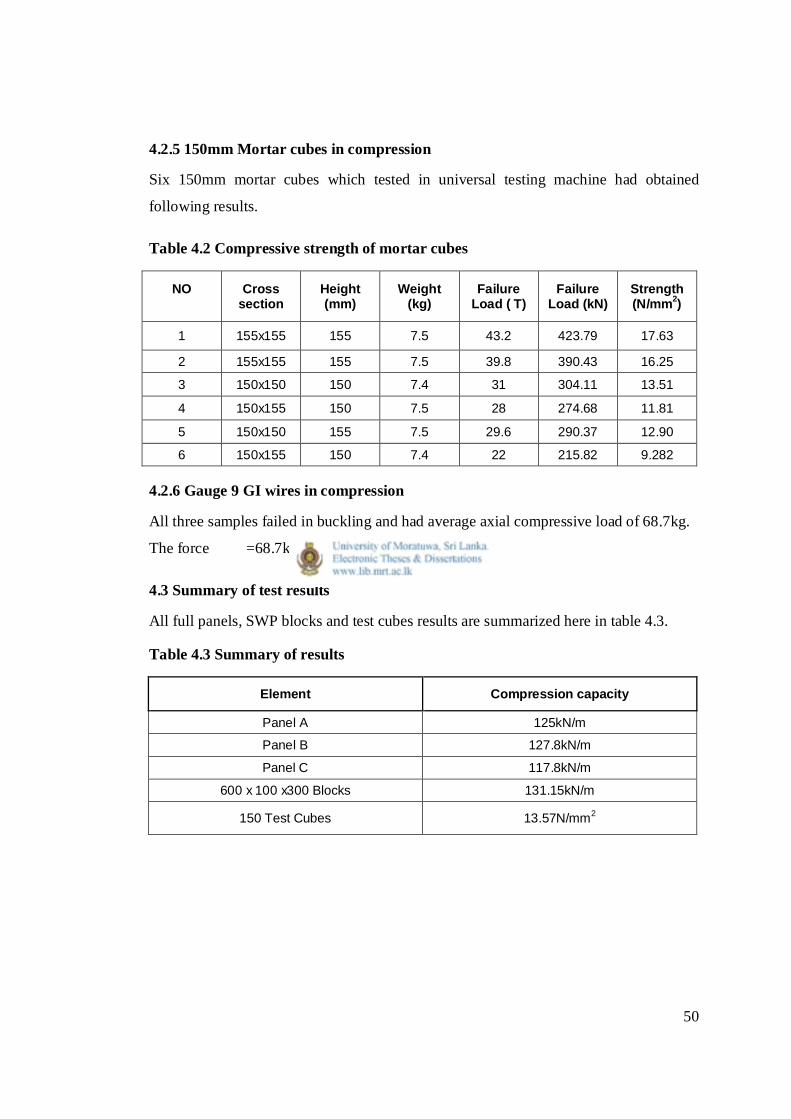
4.2.5 150mm Mortar cubes in compression
Six 150mm mortar cubes which tested in universal testing machine had obtained
following results.
Table 4.2 Compressive strength of mortar cubes
NO
Cross section
Height (mm)
Weight (kg)
Failure Load ( T)
Failure Load (kN)
Strength (N/mm2)
1 155x155 155 7.5 43.2 423.79 17.63
2 155x155 155 7.5 39.8 390.43 16.25
3 150x150 150 7.4 31 304.11 13.51
4 150x155 150 7.5 28 274.68 11.81
5 150x150 155 7.5 29.6 290.37 12.90
6 150x155 150 7.4 22 215.82 9.282
4.2.6 Gauge 9 GI wires in compression
All three samples failed in buckling and had average axial compressive load of 68.7kg.
The force =68.7kg x 9.81ms-2 = 674 N
4.3 Summary of test results
All full panels, SWP blocks and test cubes results are summarized here in table 4.3.
Table 4.3 Summary of results
Element Compression capacity
Panel A 125kN/m
Panel B 127.8kN/m
Panel C 117.8kN/m
600 x 100 x300 Blocks 131.15kN/m
150 Test Cubes 13.57N/mm2

51
4.4 Estimation of axial load capacity according to literature
Only BOCA (1999) and ICBO (1999) reports provide allowable axial load capacity of
mortar Wythe SWPs. Most other literatures deal with concrete Wythe SWPs.
4.4.1 BOCA (1999)
Fig 2.5 shows BOCA (1999) specified panel. When considering Micro Constructions
50mm insulation thickness panel with that, following compatibilities and
incompatibilities were found.
Compatibilities
1. Mortar wythes of 25mm thickness used
2. Similar gauge 12 GI wire mesh reinforcements used
3. Minimum compressive stress of mortar specified is 10.35
MPa which is 13.57 Mpa of Micro construction panel
Incompatibilities
1. Insulation thickness specified by BOCA (1999) is 100mm
and the test panels used of Micro constructions is 50mm.
Therefore overall thickness varied between 100mm to
150mm.
2. Separate gauge 10 GI wire trusses at 150mm centres specified
by BOCA (1999) and gauge 9 GI wires welded to main
meshes at 100mm centres system used in Micro construction
system.
105kN/m allowable axial load is specified for 2400mm high SWP in BOCA (1999). It
also specifies factor of 2.5 in conversion between allowable and ultimate axial load.
Therefore ultimate axial load by BOCA (1999) increases to 262.5kN/m.
52
4.4.2 ICBO (1999)
Fig 2.6 shows ICBO (1999) specified panel. When considering Micro Constructions
50mm insulation thickness panel with that, following compatibilities and
incompatibilities were found.
Compatibilities
1. Mortar wythes used in both
2. GI wire mesh reinforcements used
3. Minimum compressive stress of mortar specified is 13.8 MPa
which is 13.57 MPa of Micro construction panel
Incompatibilities
1. Insulation thickness specified by ICBO (1999) is 112mm and
the test panels used of Micro constructions is 50mm.
Therefore overall thickness varied between 100mm to
150mm.
2. ICBO (1999) wythe thickness of 18mm is lesser than Micro
construction which is 25mm.
3. Gauge 14 wire meshes specifies in ICBO (1999) which is
lesser of Micro constructions gauge 12 mesh.
4. Separate gauge 10 GI wire trusses at 150mm centres specified
by ICBO (1999) and gauge 9 GI wires welded to main
meshes at 100mm centres system used in Micro construction
system.
43.8 kN/m allowable axial load is specified for 2400mm high SWP in ICBO
(1999). The report does not mention about ultimate load capacity.
53
4.5 Discussion
4.5.1 Comparison of Panel A with BOCA (1999)
Panel A which was the panel without opening had an axial compression capacity of
125kN/m at ultimate limit state. Consider this with BOCA (1999) of 262kN/m for
2400mm height, it seems Micro constructions’ SWP has lower capacity. Explanation
for this difference may be due to incompatibilities mentioned in section 4.4.1. For an
example overall thicknesses of panels were different.
It was observed when SWP under loading cracks had occurred near bottom and top
surface, i.e. loading surfaces. Also lateral deflection occurred was much less (5mm).
Therefore, failure was not due to slenderness. If SWP had perfectly worked edges and
timber pieces introduced at loading surfaces, much higher ultimate axial load may be
achieved.
4.5.2 Comparison between Panel A and ICBO (1999)
If we assume same 2.5 conversion factor between allowable and ultimate axial load for
ICBO (1999) report, 43.8kN/m x 2.5 = 109.5kN/m ultimate capacity can be predicted.
Then Micro constructions SWP axial loading capacity is higher than that recommended
by ICBO (1999). Although ICBO (1999) recommended SWP and Micro constructions
panel have some incompatibilities as mentioned in section 4.4.2, the code is more
suitable to estimate load bearing capacity of Micro constructions’ SWPs.
4.5.3 Load bearing reduction due to opening
Experimental results in table 4.3 illustrates three SWP had axial compression capacity
between 117 kN/m and 128 kN/m. The difference is only about 10%. Panel B which
had an opening got the highest bearing capacity. Therefore results conclude that the
mentioned opening size in this specific orientation in 2400mm x 1200mm x 100mm
thick panels dose not effect load bearing capacity. Panel C had the highest deflection of
25mm. Although in those experiments we assume zero eccentricity, practically this may

54
not be true, because there was no proper method to apply axial load directly in its
centroid. This eccentricity problem may have caused higher lateral deflection in panel
C.
4.5.4 Compression capacity of SWP blocks
SWP blocks of size 600mm x 100mm x 300mm had average axial capacity of
131kN/m. The magnitude is nearly equals that of 2400m high panels. This result is also
an additional evidence to prove that 2400mm panels failed not due to slenderness.
4.5.5 Comparison of SWP blocks and panels with BS 5628-Part 1
When we consider this results with BS 5628-1 (Use of masonry) table 7 (Capacity
reduction factor, b) blocks compressive capacity can be predicted.
hef/tef= 2400mm/100mm =24
b=0.53
Assume table 2 (Characteristic compressive strength of masonry, fk ) part c as hollow
blocks strength is compatible with SWP for lower grades of blocks, then strength of
masonry panel is equal to that of block. Therefore block should get 125kN/m / 0.53=
235kN/m axial capacity. Since this is not observed we can assume either blocks quality
were much poor or SWPs don’t agree with BS5628.
SWP blocks had 1.31N/mm2 ultimate compressive strength. BS 5628- Part 1, table 2
specifies minimum compressive strength of 2.8N/mm2. This is also a negative point to
use of masonry code in SWP.
The tested blocks had maximum of six, gauge 9 wire diagonal members of truss
elements in its 300mm height. Therefore 600mm x 300mm x 100mm SWP blocks had
low amount of shear connectors. Therefore, blocks’ shear strength between Wythes was
much less than that of 2400mm high SWPs. This higher amount of shear connectors led
to higher confinement in 2400 high SWPs. Therefore, normal hollow blocks strengths’

55
and masonry panels’ strength is in opposite order compared to sandwich block and full
panels’ strength.
4.5.6 Finite element modelling
Most of the literature, they mentioned finite element (FEM) analysis which carried out
parallel to their laboratory experiments. But their both cases did not match well. For
example
(1) Fig. 20, Benayoune et al. (2005b) extracted under as Fig. 4.7 shows
lateral deflection vs. load at mid height of 1400mm high panel for both FEM
and experimental results. Local deviations in experimental result graph did not
indicated in FEM case. We can assume buckling effects of diagonal truss
elements did not correctly predicted by FEM.
Fig. 4.7 Eccentric load vs. lateral deflection for PA1 at mid-height of panel the
panel
Source: Benayoune et al. (2005b)
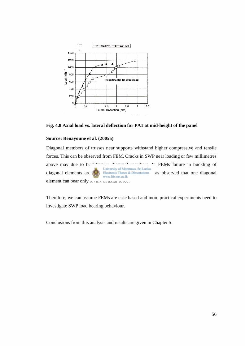
(2) Fig. 14, Benayoune et al. (2005a) extracted under as fig. 4.8 shows
similar graph for 1400mm height panel. There FEM graph had local deviations
which was not indicated by experimental case.
56
Fig. 4.8 Axial load vs. lateral deflection for PA1 at mid-height of the panel
Source: Benayoune et al. (2005a)
Diagonal members of trusses near supports withstand higher compressive and tensile
forces. This can be observed from FEM. Cracks in SWP near loading or few millimetres
above may due to buckling in diagonal members. In FEMs failure in buckling of
diagonal elements are not accurately predicted. It was observed that one diagonal
element can bear only 0.7kN of axial force.
Therefore, we can assume FEMs are case based and more practical experiments need to
investigate SWP load bearing behaviour.
Conclusions from this analysis and results are given in Chapter 5.

57
Chapter-5
Conclusions and Recommendations
5.1 General Introduction
The conclusions, the future works and the recommendations are given in this chapter.
5.2 Conclusions
First objective of the research is to investigate use of codes BS5628 part 1 (Masonry),
BOCA (1999) and ICBO (1999).
BS 5628 and BOCA (1999) can not be used to investigate load bearing capacity of SWP
(Section 4.5.1 and 4.5.5). Although ICBO (1999) codes’ specification differs to Micro
constructions SWP, it can be used to investigate load bearing capacity (Section 4.5.2).
Second objective is to find reduction in load bearing capacity due to an opening in a
SWP. Investigated window opening size in specified location does not reduce axial load
bearing capacity of SWP (Section 4.5.3).
5.3 Recommendations for future works
Need to test small size SWP blocks for example 200mm or 400mm height in
better quality to investigate compressive strength.
Window opening size and its’ location should be varied in different panel sizes to
further investigate reduction in axial load bearing capacity in SWP with opening.
Above should be repeated to investigate sandwich wall panels with 100mm EPS
layer or 150mm overall thickness.
Two timber pieces can be introduced on top and bottom of test panel to minimize
crushing failure due to surface undulations at loading points.
Thermal performance should be investigated with local SWPs.
58
Instead of two 18mm mild steel round bars, proper lateral support with rolling
effect should be used at top of the panel test set up. Deflection in those mild steel
bars noticed while testing. This may have some effect on dial gauge readings at
mid height.
Since buckling failure was not taken place for 2400mm height, heights above
2400mm can be used to investigate buckling limits for 100mm thick panels.

59
References
Benayoune, A., Samad, A. A. A., Ali, A. A. A. & Trikha, D. N. (2005). Response of
pre-cast reinforced composite sandwich panels to axial loading. Construction
and building materials 21 (2007), 677-685.
Benayoune, A., Aziz, A., Samad, A., Trikha, D. N., Abdullah, A., Ali, A., &
Ashrabov, A. A. (2005). Structural behaviour of eccentrically loaded precast
sandwich panels. Construction and building materials 20(2006), 713-724.
Benayoune, A., Samad, A. A. A., Trikha, D. N., Ali, A. A. A., & Ellinna, S. H. M.
(2006). Flexural behaviour of pre-cast concrete sandwich composite panel-
Experimental and theoretical investigations. Construction and building
materials 22(2008), 580-592.
BOCA international evaluation services research report 94-60. (1999). IL. pp 1-9.
BS 5628-Part1. (1992). Structural use of unreinforced masonry. British standards
institutions.
Bush, T.D. & Stine, G.L. (1994, March/April). Flexural analysis of composite pre cast
concrete sandwich panels with continues truss connectors. PCI Journal, 39(2),
112-121.
Bush, T. D. & Wu, Z. (1998, September/October). Flexural analysis of prestressed
concrete sandwich panels with truss connectors. PCI Journal, 43(5), 76-86.
60
Chandrasena, S.H.P.K. (2010, December 02). Effect of corrosion on compressive
strength of structurally insulated Kio panel (Unpublished graduate diploma
thesis). City & Guilds, Level 6, Access tower, 278, Union Place, Colombo 02,
Sri Lanka.
Department of Civil Engineering, University of Moratuwa. (2010, November 23).
Tests on 3D insulated Micro panels for compressive & flexural strengths.
(Reference NO: CE/GA17/ST/2010/33).
Einea, A., Salmon, D.C., Tadros, M.K. & Culp T. (1994, July/August). A new
structurally and thermally efficient precast sandwich panel system. PCI
Journal, 39(4) 90-101.
ICBO evaluation service, Inc. (1999, June 1). ER-5154. California. pp 1-6.
PCI Committee. (1997, March/April). State-of-the-art of precast/prestressed sandwich
wall panels. PCI Journal, 42( 2).
Pessiki, S. & Mlynarczyk, A. (2003, March/April). Experimental evaluation of the
composite behavior of precast concrete sandwich wall panels. PCI Journal,
48(2) 54-71.