Embed Size (px)
Citation preview

GESTS Int’l Trans. Computer Science and Engr., Vol.20, No.1 107
GESTS-Oct.2005
A Study on the Correction of Non-Linear Bias Error of an Infrared Range Finder Sensor for a Mobile Robot
using Neural Network
Je-Goon Ryu1, Hyeon-Min Shim2, Jae-Ho Shin2, Eung-Hyuk Lee3, Seung-Hong Hong2, and Pyung-Soo Kim3
1 Intelligence Healthcare System Research Center, Korea Polytechnic University, Korea [email protected]
2 Department of Electronic Engineering, Inha University, Korea [email protected]
[email protected] [email protected]
3 Department of Electronic Engineering, Korea Polytechnic University, Korea {ehlee, pskim}@kpu.ac.kr
Abstract. The infrared range finder for a mobile robot has the advantages of the low sensing cost and detecting all objects in front of the mobile robot after sensing. However, it has some non-linear bias errors, the measurement data represents the Gaussian distribution, and the variance of measurement error in-creases in proportion to distance. This paper set a goal to analyze the character-istics of an infrared range finder and to correct the non-linear bias errors. The corrected infrared range finder can be utilized as an effective alternative to other sensors in indoor environment.
1 Introduction
A mobile robot collects information about its environment through external sensors. This is combined with the information provided by internal sensors and both of them are utilized to do navigation tasks. External sensors used in the mobile robot are ultra-sonic, infrared, and laser sensors, vision cameras, and others. Each of them provides readings with a degree of uncertainty depending on the sensor characteristics.
Many techniques have been studied in the process of integrating data from differ-ent sensors[2]. These methods translate the different sensory inputs into reliable esti-mates that can be used by other navigation subsystems. Luo[3] shows the advantages gained through the use of multi-sensory information as a combination of four aspects: redundancy, complementariness, timeliness and cost of information.
Among External sensors, ultrasonic sensors have been used mainly to recognize environment[1], because the sensors have the advantages of the low cost and the possibility of real time measurement. Sonar sensors can measure distances up to nine meters[11], on the other hand, short distances are very imprecise and they have many problems with multiple reflections and wide beam width[3]. The two measurement

108 A Study on the Correction of Non-Linear Bias Error
GESTS-Oct.2005
characteristics to be improved are range accuracy and angular resolution. One is to use optimal filtering to better determine the reception moment of the ultrasonic wave. Also, by utilizing an ultrasonic linear array, it verifies the improvement of using the ultrasonic sensors[12]. The improvements are, however, often attained to the detri-ment of cost effectiveness and simplicity.
Some infrared sensors can measure up to eighty centimeters with less uncertainty than sonar. Also an infrared range finder can detect all objects in front of the mobile robot after sensing. Therefore, it will be substituted for ultrasonic sensors or used more than sonar sensors as a distance recognition sensor for the mobile robot. Benet [9] proposed the way to acquire more accurate angles and distances with the consid-eration of the reflectance characteristics of the object surface. But the method limited the measurement confidence interval by 1metres, and did not consider nonlinearities.
This paper aims at analyzing the characteristics of the infrared range finder by us-ing relatively low cost IR scanner, and correcting the irregular effective elements by applying the infrared range finder to the measurement distance sensor. When working with neural networks, a key point is data gathering. In Section 2, we present the mod-els of the sensors, a description of the data gathering process, and a characteristic analysis of the measurement data. In Section 3, we describe the neural networks we used, and the training procedure. In Section 4, we show the conducting experiments and some results. Finally, in Section 5, we present some conclusions.
2 The Characteristics of Infrared Range Finder Sensor
2.1 Structure and Specification of Infrared Range Finder Sensor
In this research, the PBS Series of Hokuyo Company is utilized as the infrared range finder. As shown in Fig. 1, the PBS sensor has a detector on the bottom and an emit-ter on the top. When the step motor placed the two reflective mirrors rotating, the measurement direction is determined. Scanning angle (Detection area) is 180 degrees. Operation principle is that the semicircular field is scanned by LED (lambda=880nm) and the coordinates are calculated by measuring the distance to the object and its step angle and then it detects obstacle in setting area. The module can measure from 10 centimeters up to 300 centimeters with accuracy and resolution depending on the distance. (Fig. 1 (b))
(a)

GESTS Int’l Trans. Computer Science and Engr., Vol.20, No.1 109
GESTS-Oct.2005
(b)
Fig. 1. (a) Structure of the PBS Series, (b) Scanning range and direction of the PBS Series.
Table 1. Specification of the PBS Series
Item Specification Power Source 24VDC ( allowed range 18 to 30DVC including ripple ) Current Consumption 250mA or less Response Time 180ms or less ( scanning speed 1 rev./ 100ms) Scanning Angle 180° Interface RS-232C
There are three fundamental kinds of errors regarding the infrared sensors:
Object color/reflectivity. Since the light reflectivity varies with color, the darker the object, the further it appears. The accuracy degrades quickly with the distance. The object may even be undetected.
Global illumination. As a regular illumination contains light in the infrared band, the brighter the light, the further the object appears.
Quantization error. This sensor converts the measurement up to 8 bits. This conversion is not linear in the full range, and therefore, the further the ob-ject, the less accurate is the reading.
2.2 The Characteristic Analysis of Infrared Range Finder
For the characteristic analysis of the PBS Series, the robotics platform used the mo-bile robot with a diameter of 387 millimeters. It has two differentially steered wheels, two caster wheels, and 12 pairs of sonar sensors, symmetrically and radially oriented at the intervals of 30 degrees, and finally, the PBS Series sensor is placed in front of the mobile robot.
The data acquisition procedure is as follows. A flat board in the front of the mobile robot is established. The mobile robot gathers the distance data of 200 samples at the intervals of 10cm while moving to the object from 300cm to 10cm. This data set has been used for neural network training.

110 A Study on the Correction of Non-Linear Bias Error
GESTS-Oct.2005
Fig. 2. The PBS Series built in front of the mobile robot
As shown in Fig. 3, the output of the PBS sensor represents non-linear bias value. Due to this nonlinearity, we have trained the sensor using neural networks.
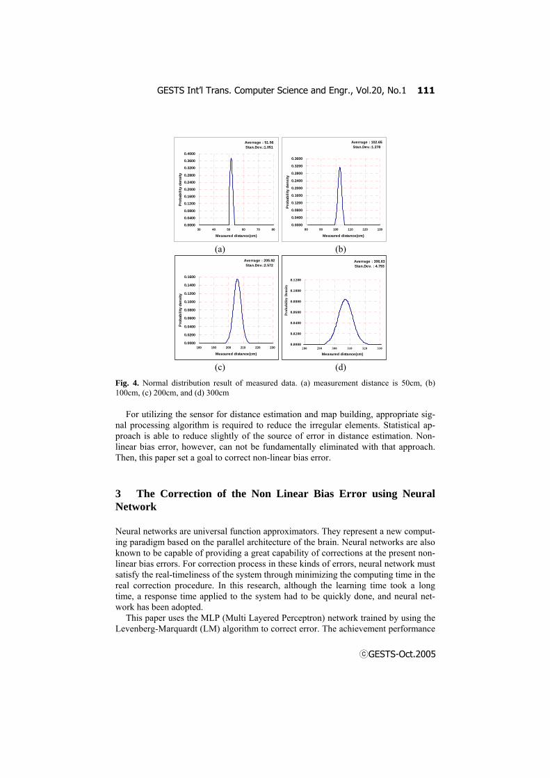
Statistical analysis was carried out to analyze more accurately for the characteris-tics of the infrared range finder with the measurement data. After calculating the average and the standard deviation of samples gained at each measurement distance 50cm, 100cm, 200cm, and 300cm, the probability density function based on these estimation values is defined. Fig. 4 illuminates the probability density function with the Gaussian distribution on the measurement data.
The two characteristics of the infrared range finder sensor are summarized through these analyses. First, the samples show the Gaussian distribution. And the variance of measurement error increases in proportion to distance. Second, the measurement data represent the non-linear bias error in comparison to the real distance.
0
50
100
150
200
250
300
350
10 30 50 70 90 110
130
150
170
190
210
230
250
270
290
Distance from sensor to object (cm)
Mea
sure
d di
stan
ce(c
m)
Actual Distance Measured Distance
Fig. 3. Result of distance measurement with the PBS Series. Where X axis is the actual dis-tance between a mobile robot and an object, and Y axis is the measurement distance between them
GESTS Int’l Trans. Computer Science and Engr., Vol.20, No.1 111
GESTS-Oct.2005
Averrage : 51.56Stan.Dev.:1.051
0.0000
0.0400
0.0800
0.1200
0.1600
0.2000
0.2400
0.2800
0.3200
0.3600
0.4000
30 40 50 60 70 80
Measured distance(cm)
Pro
babi
lity
dens
ity
Averrage : 102.65Stan.Dev.:1.278
0.0000
0.0400
0.0800
0.1200
0.1600
0.2000
0.2400
0.2800
0.3200
0.3600
80 90 100 110 120 130
Measured distance(cm)
Prob
abili
ty d
ensi
ty
(a) (b)
Averrage : 205.92Stan.Dev.:2.572
0.0000
0.0200
0.0400
0.0600
0.0800
0.1000
0.1200
0.1400
0.1600
180 190 200 210 220 230
Measured distance(cm)
Prob
abili
ty d
ensi
ty
Averrage : 306.63Stan.Dev. : 4.793
0.0000
0.0200
0.0400
0.0600
0.0800
0.1000
0.1200
280 290 300 310 320 330
Measured distance(cm)
Prob
abili
ty D
ensi
ty
(c) (d)
Fig. 4. Normal distribution result of measured data. (a) measurement distance is 50cm, (b) 100cm, (c) 200cm, and (d) 300cm
For utilizing the sensor for distance estimation and map building, appropriate sig-nal processing algorithm is required to reduce the irregular elements. Statistical ap-proach is able to reduce slightly of the source of error in distance estimation. Non-linear bias error, however, can not be fundamentally eliminated with that approach. Then, this paper set a goal to correct non-linear bias error.
3 The Correction of the Non Linear Bias Error using Neural Network
Neural networks are universal function approximators. They represent a new comput-ing paradigm based on the parallel architecture of the brain. Neural networks are also known to be capable of providing a great capability of corrections at the present non-linear bias errors. For correction process in these kinds of errors, neural network must satisfy the real-timeliness of the system through minimizing the computing time in the real correction procedure. In this research, although the learning time took a long time, a response time applied to the system had to be quickly done, and neural net-work has been adopted.
This paper uses the MLP (Multi Layered Perceptron) network trained by using the Levenberg-Marquardt (LM) algorithm to correct error. The achievement performance
112 A Study on the Correction of Non-Linear Bias Error
GESTS-Oct.2005
of the MLP network will highly depend on the structure of the network and training algorithm. Then, the LM algorithm has been selected to train the network. It has been shown that the algorithm has much better learning rate than the famous back propaga-tion algorithm[8]. The LM algorithm is an approximation of the Gaussian-Newton technique, which generally provides much faster learning rate than back propagation that is based on the steepest decent technique.
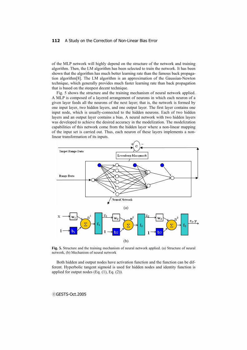
Fig. 5 shows the structure and the training mechanism of neural network applied. A MLP is composed of a layered arrangement of neurons in which each neuron of a given layer feeds all the neurons of the next layer; that is, the network is formed by one input layer, two hidden layers, and one output layer. The first layer contains one input node, which is usually-connected to the hidden neurons. Each of two hidden layers and an output layer contains a bias. A neural network with two hidden layers was developed to achieve the desired accuracy in the modelization. The modelization capabilities of this network come from the hidden layer where a non-linear mapping of the input set is carried out. Thus, each neuron of these layers implements a non-linear transformation of its inputs.
(a)
(b)
Fig. 5. Structure and the training mechanism of neural network applied. (a) Structure of neural network, (b) Mechanism of neural network
Both hidden and output nodes have activation function and the function can be dif-ferent. Hyperbolic tangent sigmoid is used for hidden nodes and identity function is applied for output nodes (Eq. (1), Eq. (2)).

GESTS Int’l Trans. Computer Science and Engr., Vol.20, No.1 113
GESTS-Oct.2005
x
x
eenfnf +
−
+−
==11)()( 21 . (1)
nnf =)(3 . (2)
The output combined with each activation functions is shown as followings.
332211123
3 ))((( bWbWbxWfffzy TTTm +++== (3)
The input data of neural network is gathered with the same method in Section 2. A
mean value of measurement data in each distance is used for the input data (Range data). Target range data is the real distance between the sensor and the object.
For training neural network, the LM algorithm that is efficient for solving the non-linear problems is used. Learning rate is 0.01. If the RMS error that is the difference of the output value from target value is under 5105.2 −× , the learning comes to an end. The training comes to a goal at 254 times.
4 Experimental Result
The results for the model proposed have been obtained within a MLP with architec-ture ( 1261 ××× ). Interconnection weights as the training completed is shown in (Eq. (4)).
⎥⎥⎥⎥⎥⎥⎥⎥
⎦
⎤
⎢⎢⎢⎢⎢⎢⎢⎢
⎣
⎡
−−
−−−
=
476.4338.3
411.3956.1292.5795.4
1W,
⎥⎥⎥⎥⎥⎥⎥⎥
⎦
⎤
⎢⎢⎢⎢⎢⎢⎢⎢
⎣
⎡
−
−=
081.1465.18336.3585.5764.15392.17
1b
⎥⎥⎥⎥⎥⎥⎥⎥
⎦
⎤
⎢⎢⎢⎢⎢⎢⎢⎢
⎣
⎡
−−−−−
−−−−
=
495.1105.1585.3400.1374.0
818.0
335.0811.0173.1539.0
528.2170.1
2W , ⎥
⎦
⎤⎢⎣
⎡−−
=722.1994.4
2b
[ ]495.1675.33 −−=W , [ ]836.03 −=b
(4)

114 A Study on the Correction of Non-Linear Bias Error
GESTS-Oct.2005
With the interconnection weights, we gained the measurement distance of the PBS Series sensor. Fig. 6 shows the results.
0
50
100
150
200
250
300
350
10 30 50 70 90 110
130
150
170
190
210
230
250
270
290
Distance from sensor to object (cm)
Mea
sure
d D
ista
nce(
cm)
Actual Distance Measured Distance
Fig. 6. Result of correction using neural network
The results have been obviously better. It can be seen that the measurement dis-tance is linearly yielded. Also, the standard normal distribution of each measurement distance (50cm, 100cm, 200cm, and 300cm) represents that the center points of meas-urement distance.
Standard Normal Distribution
0.00
0.10
0.20
0.30
0.40
-30 -25 -20 -15 -10 -5 0 5 10 15 20 25 30Standard Distance (cm)
Prob
abili
ty D
ensi
ty
Distance 50cmDistance 100cmDistance 200cmDistance 300cm
Fig. 7. Standard normal distribution of each measurement distance (50cm, 100cm, 200cm, and 300cm). 300cm measurement data shows that it spreads more than the others

GESTS Int’l Trans. Computer Science and Engr., Vol.20, No.1 115
GESTS-Oct.2005
Fig. 8. Measurement data of IR scanner before and after applying neural network in the ex-periment environment.
We construct the experiment environment of 600×450cm size for navigation of ro-bot. Fig. 8 represents data of IR scanner before and after correction of non linear bias error. Measurement data after applying neural network show the correct distance between robot and obstacles. This show that corrected data can be utilized with dis-tance value for obstacle detection, local map building, and localization of robot.
5 Conclusion
In this paper, we analyze the data characteristic of the infrared range finder, and set a goal of correcting the irregular elements in using the infrared range finder as the envi-ronment recognition system for mobile robot. From the research, the infrared range finder sensor has the increasing error with the distance of the objects gets farther away, and also has non-linear bias errors. By using the neural network proposed in this paper, we verify that non-linear bias errors are efficiently eliminated. Then, it can be utilized for global map building in the mobile robot navigation.
Acknowledgment
This research (paper) is financially supported by the Ministry of Information and Communication Republic of Korea for the Project of the Information and Commu-nication Industrial Competitiveness.

116 A Study on the Correction of Non-Linear Bias Error
GESTS-Oct.2005
References
[1] Borenstein, J., koren, Y., “Obstacle avoidance with ultrasonic sensors,” IEEE J. Robot-ics and Automation, 4(1), pp. 213–218, 1988.
[2] Flynn, A.M., “Combining sonar and infrared sensor for mobile robot navigation,” Intl. Journal Robot. Res., pp. 5–14, 1988.
[3] Luo, R.C., Kay, M.G., “Multisensor integration and fusion in intelligent systems,” IEEE Transaction on Systems, Man and Cybernetics, 19(5) , pp. 901–931, 1989.
[4] Kurz, A., “Constructing maps for mobile robot navigation based on ultrasonic range data,” IEEE Trans, on System, Man, and Cybernetics, 26(2), pp. 233–242, 1996.
[5] Leonard, J., Durannt-Whyte, H., “Directed sonar sensing for mobile robot navigation,” Kluwer, Dordrecht, The Netherlands, 1992.
[6] Ming Yang, S.L. Hill, J.O. Gray, “Design of ultrasonic linear array for multi-objects identification,” IEEE/RSI International Conference on Intelligent Robots and Systems, pp. 1625–1632, 1992.
[7] H. Hamadene, E. Colle, “A method based on neural networks for the recognition of the environment scanned by ultrasonic sensor,” EUFIT’96 Fourth European Congress on Intelligent Techniques and soft Computing, Vol. 1, pp. 249-254, Aachen, Germany, Sep. 1996.
[8] Hagan M.T. and Menhaj M., “Training Feedback Networks with the Marquardt Algo-rithm,” IEEE Trans. on Neural Networks, Vol. 5, No. 6, 989-993
[9] G. Benet, F. Blanes, J. E. Simo, P. Peres, “Using infrared sensors for distance measure-ment in mobile robots,” Int. Journal of Robotics and Autonomous Systems, Vol.40. pp. 255–266, 2002.
[10] M. Norgaard, O. Ravn, N. K. Poulsen, L. L. Hansen, ”Neural Networks for Modeling and Control of Dynamic Systems,” a practitioners handbook, Springer, 2000.
[11] Data sheets for the Polaroid Ultrasonic Range-Finder, Polaroid Corporation [12] Teruko YATA, Akihisa OHYA, shin’ichi YUTA, “A fast and accurate Sonar-ring Sen-
sor for a Mobile Robot,” Proc. of IEEE Int. Conf. On Robotics and Automation, Detroit, Michigan, pp. 630-636, 1999.
Biography
▲ Name: Je-Goon Ryu
Address: 401-401, Bucheon Techno-Park, #193, Yakdae-Dong, Wonmi-Gu, Bucheon-City, Gyeonggi-Do, 420-734, Korea Education & Work experience: He received the B.S. degree in Electronic Engineering from Inha University, Incheon, Korea, in 1999, and the M.S. degree in Electronic Engineering from Inha University, Incheon, Korea, in 2004, respectively. From 1999 to 2001, he was a junior researcher at R&D of MECA Information
Communication Co. Ltd. Since 2004, he has been a junior researcher at Intelligence Healthcare system Research Center, Korea Polytechnic University. Tel: +82-2-32-327-8838 E-mail: [email protected] Other Information : His main research interests are in the areas of service robot control, mobile healthcare system, robot vision, embedded system, and various industrial applica-tions.
GESTS Int’l Trans. Computer Science and Engr., Vol.20, No.1 117
GESTS-Oct.2005
▲ Name: Hyeon Min Shim
Address: 253, Yonghyun-Dong, Nam-gu, Incheon, 402-751, Ko-rea Education & Work experience: He received the B.S. degree in Electronic Engineering from Inha University in 2001. He received the M.S. degree in Electronic Engineering from Inha University in 2003, respectively. He is currently working toward his Ph.D. at Inha University in the area of service robot system.
Tel: +82-32-868-4691 E-mail: [email protected] Other information: His main research interests are in the areas of service robot control system, motion planning, localization, map building and sensor systems.
▲ Name: Jae-Ho Shin
Address: 195-42, Anyang 7-dong, Manan-gu, Anyang-si, Gyeonggi-do, Korea Education & Work experience: He received the B.S. degree in Bio Medical Engineering from Inje University, Kimhae, Korea, in 1993. He received the M.S. degree and finished course of the Ph.D. degree in Electronics Engineering from School of Electronic En-gineering from Inha University, Inchon, Korea, in 1995 and 1987, respectively. From 1993 to 1994, he was a researcher at Indus-
trial Robot Lab. of Korea Atomic Energy Research Institute. From 1996 to 2002, he was a researcher at Medison Co., Ltd. Since 2002, he has been CEO of HuBDIC Co., Ltd. Tel: +82-2-31-442-4499 E-mail: [email protected] Other information: His main research interests are in the areas of service robot control, hospital healthcare system, home healthcare products and various healthcare applications.
▲ Name: Eung-Hyuk Lee
Address: 2121, Jungwang-Dong, Shihung-City, Kyonggi-Do, 429-793, Korea Education & Work experience: He received the B.S. degree in Electrionics Engineering from Inha University, Inchon, Korea, in 1985, and the M.S. degree and the Ph.D. degree in Electronics Engineering from School of Electronic Engineering from Inha University, Inchon, Korea, in 1987 and 1987, respectively. From 1987 to 1992, he was a researcher at Industrial Robot Lab. of
Daewoo Heavy Industry Co. Ltd. From 1995 to 2000, he was a assistive professor at Dept. of Computer Engineering in Konyang University. Since 2000, he has been with the Depart-ment of Electronics Engineering at Korea Polytechnic University. Tel: +82-2-31-496-8267 E-mail: [email protected] Other information: His main research interests are in the areas of service robot control, mobile healthcare system, image processing and various industrial applications.

118 A Study on the Correction of Non-Linear Bias Error
GESTS-Oct.2005
▲ Name: Seung-Hong Hong
Address: 253, Yonghyun-Dong, Nam-gu, Incheon, 402-751, Korea Education & Work experience: He received the B.S. degree in Electronical Engineering from Inha University in 1963. He re-ceived the M.S. degree in Electronical Engineering from Inha University in 1966, and the Ph.D. degree at the School of Bio-medical Engineering from Tokyo University, Japan in 1975, re-spectively. He was a director and chairman at the Institute of Electronic Engineer of Korea from 1981 to 1994. He was a direc-
tor, vice chairman, and chairman at the IEEE Korea Section from 1983 to 1997. He has been with the Department of Electronics Engineering at Inha University. Tel : +82-32-860-7412 E-mail: [email protected] Other information: His main research interests are in the areas of bio-signal processing, re-habilitation engineering, medical image processing.
▲ Name: Pyung-Soo Kim
Address: 2121, Jungwang-Dong, Shihung-City, Kyonggi-Do, 429-793, Korea Education & Work experience: He received the B.S. degree in Electrical Engineering from Inha University in 1994. He received the M.S. degree in Control and Instrumentation Engineering and the Ph.D. degree at the School of Electrical Engineering and Computer Science from Seoul National University in 1996 and 2001, respec-
tively. From 2001 to 2005, he was a senior researcher at the Digital Media R&D Center of Samsung Electronics Co. Ltd. Since 2005, he has been with the Department of Electronics Engineering at Korea Polytechnic University. Tel: +82-2-31-496-8413 E-mail: [email protected] Other information: His main research interests are in the areas of system software solu-tions, wireless mobile networks, internet protocol design, statistical signal processing, and various industrial applications.