Embed Size (px)
Citation preview
A study on the growth mechanism and the process parameters controlling aluminium
oxide thin films deposition by pulsed pressure MOCVD
Hari Murthy, S.S Miya, Susan Krumdieck
Abstract
Aluminum oxide thin films were deposited on silicon substrates under different deposition
conditions using pulse pressure metal organic chemical vapour deposition (PP-MOCVD). The
current study investigates into the growth mechanism of the deposited film and the control of
the film morphology by varying the processing parameters of PP-MOCVD - choice of
solvent, concentration, and presence of a shield. Aluminum sec-butoxide (ASB) was used as
the aluminum source while hexane and toluene were used as the solvents. The films were
deposited at 475oC at different precursor concentrations. It was observed that the choice of
solvent has no effect on the surface morphology, but it influenced the deposition rate. The
improved deposition rate, relatively close enthalpy of vaporisation (ΔH) values and
uniformity of the film, irrespective of the growth conditions, showed that hexane was a better
solvent for ASB than toluene. A hybrid mode of vapour deposition and vapour condensation
model for thin film growth is proposed where five different mechanisms lead to a solid film
formation. These include vapour phase deposition under low arrival rate, vapour phase
deposition under high arrival rate, Leidenfrost aerosol formation, heterogeneous particle
formation and liquid droplet impingement. The important parameter that needs to be
controlled is the precursor flux arrival rate which can be controlled by varying the precursor
concentration, use of a solvent with a low ΔH and the presence of a shield over the substrate,
which influences the surface morphology and the growth rate of the films.
Keyword: aluminium oxide, thin films, pulse, MOCVD, growth mechanism, factors
1
1.1 Introduction
1.1.1 Materials
Alumina in the form of powder or coating is a material that has wide applications in
optoelectronic and microelectronic components due to its high band gap (9 eV) as well as
wear resistant agent or protection against corrosion and temperature oxidation [1]. Alumina
films have been produced by various techniques including sol-gel synthesis [2,3], atomic
layer deposition (ALD) [4], electron beam deposition (E-beam) [5], sputtering [6], pulsed
laser deposition (PLD) [7], ultrasonic spray pyrolysis [8–11], spray deposition [12] and
chemical vapour deposition (CVD) [13].
According to Marchand et al. [14], the morphology of the films deposited depends on several
factors, such as temperature, solvent, and the substrate material. Precursor-solvent chemistry
plays a vital role when it comes to direct liquid injection (DLI) deposition techniques, with a
preference for solvents with high vapour pressure [15]. Pulse pressure MOCVD (PP-
MOCVD) is a unique variant of direct liquid injection CVD (DLI-CVD) where the precursors
are dissolved in a suitable solvent and fed into a continuously evacuated chamber via an
ultrasonic atomiser [16]. No carrier gas is used to transport the solution to the deposition
chamber. The exposure of the liquid droplets to a vacuum causes flash vaporisation
[17,18] resulting in a near-instantaneous pressure spike followed by a pump down for each
pulse. The rapid change in the chamber pressure results in the existence of an expansion mass
transport regime [19]. The injection has to be done instantaneously for the droplets to be
exposed to the minimum chamber pressure [20] which would otherwise lead to agglomeration
of particles (aerosols).
In PP-MOCVD, the deposition mechanism is determined by the precursor/solvent
compatibility, concentration, and the deposition chamber base pressure [20,21]. The
precursor/solvent compatibility can be indicated by the difference in their evaporation rate
2
estimated by comparing their enthalpies of vaporization (∆H) [21]. ΔH is the amount of heat
that needs to be absorbed for a liquid to be vaporised at a given temperature and pressure. A
liquid with a low ΔH requires less heat to be vaporised completely than another liquid with a
higher ΔH value. A significant difference in the evaporation rate of the precursor and the
solvent causes one of the components to evaporate, leaving the other component behind to
freeze during deposition. If the solvent evaporates faster than the precursor, a dry, solid
spherical particle containing the precursors (aerosols) is left behind leading to aerosol
deposition [22]. High liquid-vapour conversion can be achieved if a precursor-solvent pair is
selected such that both evaporate at the same rate. Previous work [23] on alumina precursors
has shown aluminium sec-butoxide (ASB) to be compatible with hexane and toluene with the
best growth rate observed at 475oC.
1.1.2 Condensation model
The formation of thin films from vapours is a complex process consisting of nucleation,
growth, coalescence and sometimes crystallisation [24]. Condensation and nucleation from
the vapour on a solid surface have been widely studied and used for thin film formation [25].
The condensation of the vapour occurs when its supersaturation degree reaches a critical
value, leading to the subsequent nucleation [26] and formation of liquid droplets [27].
According to the supersaturation-condensation-fusion deposition mechanism [28], the
deposition is completed in 2 stages – the first stage follows conventional CVD and is
restrained to a thin layer. As the deposition progresses, the supersaturation of the chemical
system increases, resulting in the formation of liquid droplets, which fuse to form the thin
film. Vapour condensation can be categorised as either drop-wise or film-wise condensation
[29]. In the drop-wise condensation, the formation mechanism can be explained by the liquid
3
film rupture hypothesis and the hypothesis of specific nucleation sites [30]. In the drop-wise
condensation, a stable cluster forms from the diffusion of adatoms on the surface or from the
addition of the atoms from the vapour phase [31]. In the later, the nuclei formation occurs in
specific sites, such as pits, grooves or caves. As the arrival rate increases, the thin film forms
rapidly, contracts and ruptures into nuclei and droplets, which is in line with the “hypothesis
of film rupture” [32]. The surface tension of the growing film ruptures the film ruptures into
droplets upon reaching a critical thickness. Because the adatoms of the amorphous film on the
surface are highly mobile, we can assume the surface to have a liquid-like fluidity [33]. There
are 2 types of island coalescence – solid-like (occurs during the final stages of a mono-layer
formation), and liquid-like (initial and intermediate stages of condensation of amorphous and
crystalline films). It has been modelled that for a liquid-like coalescence, under conditions of
slow growth corresponds to the diffusion mechanism of island growth under the condition of
complete condensation. For a high growth rate, disc-shaped clusters are formed on the
surface. The vacuum deposition of amorphous condensates has already been presented as 2-D
Van der Waals condensation, where the amorphous layers are formed initially followed by the
crystalline condensates produced within the amorphous film.
4
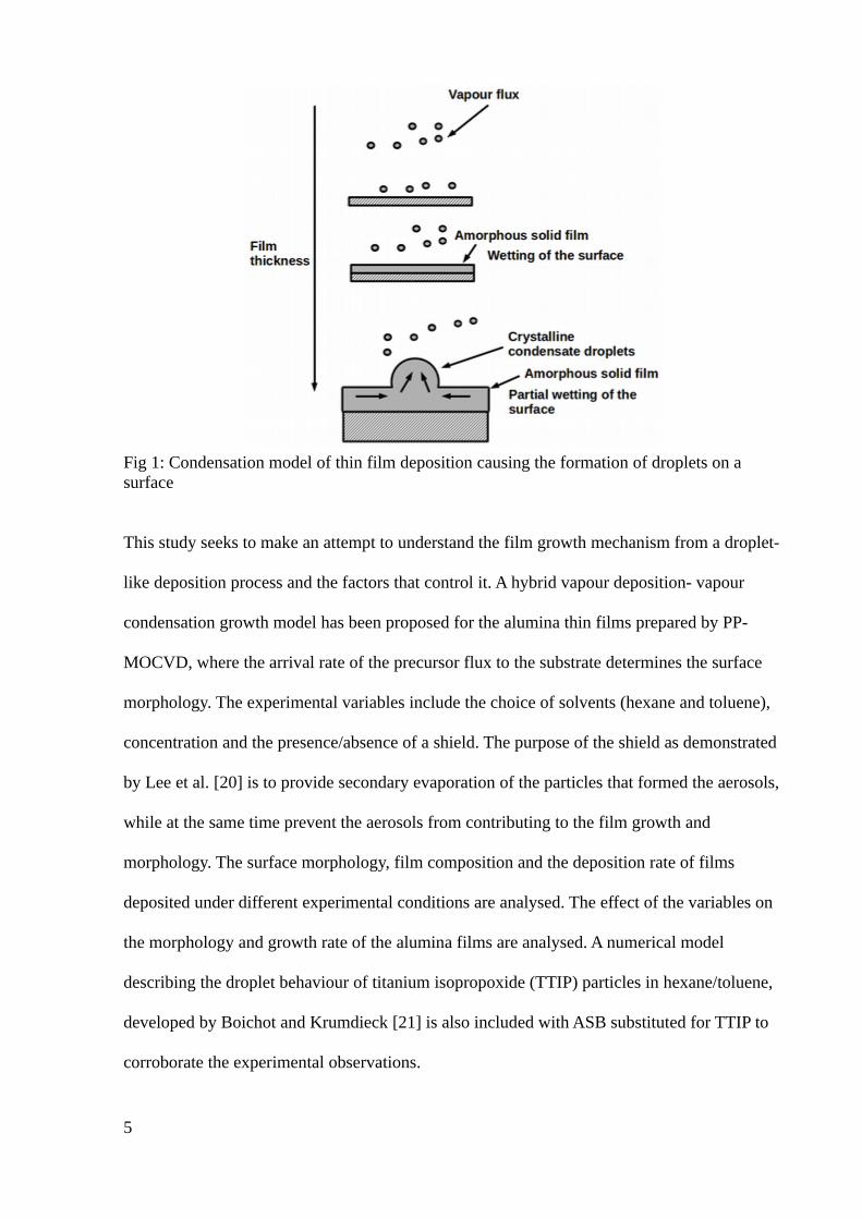
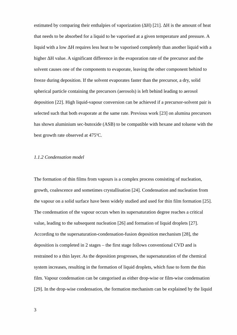
Fig 1: Condensation model of thin film deposition causing the formation of droplets on a surface
This study seeks to make an attempt to understand the film growth mechanism from a droplet-
like deposition process and the factors that control it. A hybrid vapour deposition- vapour
condensation growth model has been proposed for the alumina thin films prepared by PP-
MOCVD, where the arrival rate of the precursor flux to the substrate determines the surface
morphology. The experimental variables include the choice of solvents (hexane and toluene),
concentration and the presence/absence of a shield. The purpose of the shield as demonstrated
by Lee et al. [20] is to provide secondary evaporation of the particles that formed the aerosols,
while at the same time prevent the aerosols from contributing to the film growth and
morphology. The surface morphology, film composition and the deposition rate of films
deposited under different experimental conditions are analysed. The effect of the variables on
the morphology and growth rate of the alumina films are analysed. A numerical model
describing the droplet behaviour of titanium isopropoxide (TTIP) particles in hexane/toluene,
developed by Boichot and Krumdieck [21] is also included with ASB substituted for TTIP to
corroborate the experimental observations.
5
1.2 Materials and methods
A research-scale vertical reactor (described in [23]) was used to deposit alumina films on
(100) silicon substrates at 475oC. The temperature is so chosen as the main purpose is to
understand the growth mechanism for pulsed CVD. Pre-deposition, the substrates were
cleaned using a piranha solution (3:1 H2SO4: H2O2) followed by a dilute HF dip. ASB (Sigma-
Aldrich, >97% pure, CAS Number 2269-22-9) was used without any further purification, with
dry hexane and toluene used as the solvent.
Two concentrations (0.125 mol% and 0.5 mol%) of the precursor-solvent solution were
selected, prepared in a glovebox filled with dry N2 gas (purity >99.99%) obtained from BOC
Ltd to avoid exposure to air and moisture. The precursor solution was maintained in a
pressurised bottle (75-85 kPa) under constant stirring. The pulsing time was set at 6 sec and
the reaction chamber base pressure maintained at 100-110 Pa. The details of the varied
experimental parameters are given in Table 1. Fig 1 shows the schematics of the deposition
process and the research equipment used. A shield is placed at a distance of 15 mm from the
top of the susceptor to understand the growth mechanism.
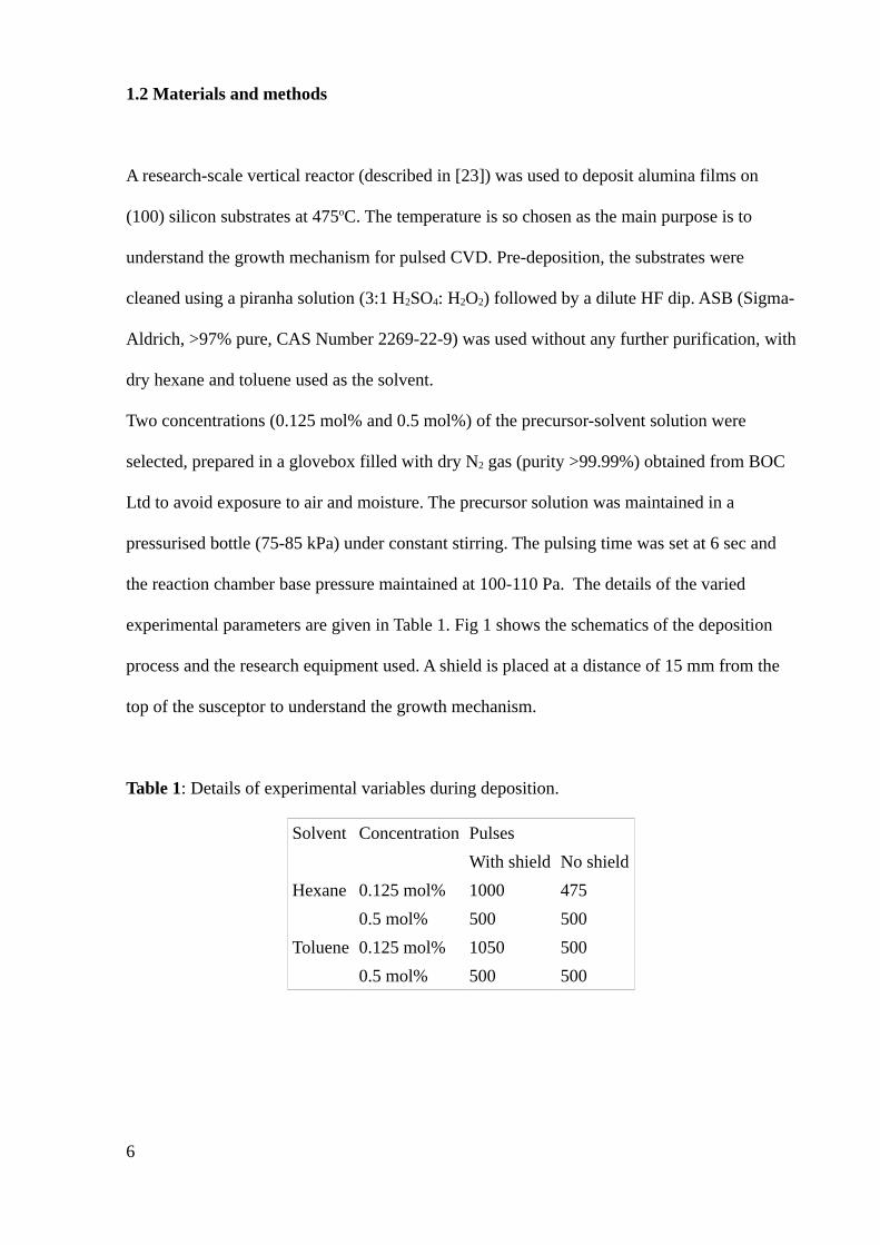
Table 1: Details of experimental variables during deposition.
Solvent Concentration Pulses
With shield No shield
Hexane 0.125 mol% 1000 475
0.5 mol% 500 500
Toluene 0.125 mol% 1050 500
0.5 mol% 500 500
6
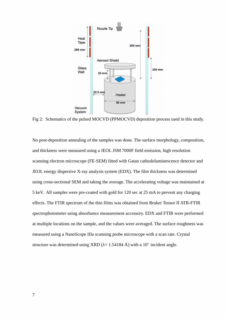
Fig 2: Schematics of the pulsed MOCVD (PPMOCVD) deposition process used in this study.
No post-deposition annealing of the samples was done. The surface morphology, composition,
and thickness were measured using a JEOL JSM 7000F field emission, high resolution
scanning electron microscope (FE-SEM) fitted with Gatan cathodoluminescence detector and
JEOL energy dispersive X-ray analysis system (EDX). The film thickness was determined
using cross-sectional SEM and taking the average. The accelerating voltage was maintained at
5 keV. All samples were pre-coated with gold for 120 sec at 25 mA to prevent any charging
effects. The FTIR spectrum of the thin films was obtained from Bruker Tensor II ATR-FTIR
spectrophotometer using absorbance measurement accessory. EDX and FTIR were performed
at multiple locations on the sample, and the values were averaged. The surface roughness was
measured using a NanoScope IIIa scanning probe microscope with a scan rate. Crystal
structure was determined using XRD (λ= 1.54184 Å) with a 10o incident angle.
7
1.3 Results and Discussion
1.3.1 Modeling droplet diameter
A model developed by Boichot and Krumdieck [21] is used to model the precursor-solvent
droplet behaviour, regarding droplet diameter/mass and chamber pressure variations.
Previous models using TTIP in hexane and toluene has suggested that a low ΔH/Cp and a low
ΔH of the components results in better vaporisation of the droplet. The model considers 3
concentrations of the precursor – 0 (solvent only), 0.125 mol% and 0.5 mol%, with a 6 sec
pulse cycle. Two reactor wall temperatures (Treactor =23oC and 223oC) are tested to see the
influence of the external heat on the chamber pressure (Preactor). Table 2 lists the key input
properties of the precursor and solvents used in the model.
The decrease in the droplet diameter (mdroplet) is given by:
dmdroplet
dt=−ϕvap , x
ϕvap , x=Adroplet2
2−αc√2π M x R(αE PSat
T droplet
√Tdroplet
−αc
Preactor
√T reactor
) M x
mdroplet=msolvent+mprecursor
--(2)
‘x’ represents the component of the droplet measured – either the pure solvent or the
precursor-solvent solution. φvap,x is the mass vaporisation flux, Adroplet is the mole fraction of
the solvent/precursor, Mx is the molar mass of the species, R is the universal gas constant, and
Psat is the vapour pressure of the solvent/precursor. The values of condensation coefficient (ɑC)
and evaporation coefficient (ɑE) are taken about 0.1 for a liquid/solid surface vaporising in a
vacuum. The negative sign indicates the decrease in the mass of the droplet with time.
8
Table 2: Input variables used in the model for droplet evaporation.
Property ASB Hexane Toluene
ΔH (J/kg) 365000* 334000 402000
Melting Point (in oC) -46 -93.5 -95
Cp (J/kg K) 2096** 2293 1720
** Specific heat capacity (Cp) of triethylaluminium is used (obtained from NIST, CAS# 97-
93-8)
* Obtained from Gelest Inc.
Fig 3 shows the reduction in the droplet diameter over the course of a pulse for a pure solvent
and precursor solution. The process can be divided into 3 stages, which affects the growth
mechanism of the thin film – instantaneous flash vaporisation, pseudo-equilibrium/solvent
evaporation (0-2.6 sec for 0.125 mol% ASB-toluene solution) and precursor evaporation (2.6-
3.4 sec for 0.125 mol% ASB-toluene solution). The flash vaporisation is the first stage where
the droplet undergoes a liquid to gas phase conversion as it is exposed to the low pressure in
the chamber [34]. A droplet with a low ΔH ensures that more of the droplet gets converted to
the vapour phase, as seen with hexane. At the beginning of the pulse, the droplets are exposed
to the minimum pressure in the chamber and undergo flash vaporisation. The decrease in the
droplet diameter is influenced by the ΔH of the solvents. Hexane, due to its lower ΔH, has a
faster decrease in the droplet diameter (23% reduction) compared to toluene (10% reduction).
Following the flash vaporisation, the solvent starts evaporating where hexane evaporates at
the rate of ~12 μm/sec and toluene evaporates at ~5 μm/sec. Solvents with a lower ΔH value
takes less time to evaporate compared to one with a higher ΔH value [23].
9
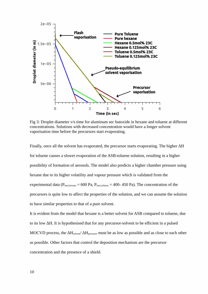
Fig 3: Droplet diameter v/s time for aluminum sec butoxide in hexane and toluene at different concentrations. Solutions with decreased concentration would have a longer solvent vaporisation time before the precursors start evaporating.
Finally, once all the solvent has evaporated, the precursor starts evaporating. The higher ΔH
for toluene causes a slower evaporation of the ASB-toluene solution, resulting in a higher
possibility of formation of aerosols. The model also predicts a higher chamber pressure using
hexane due to its higher volatility and vapour pressure which is validated from the
experimental data (Pmax,hexane = 600 Pa, Pmax,toluene = 400- 450 Pa). The concentration of the
precursors is quite low to affect the properties of the solution, and we can assume the solution
to have similar properties to that of a pure solvent.
It is evident from the model that hexane is a better solvent for ASB compared to toluene, due
to its low ΔH. It is hypothesised that for any precursor-solvent to be efficient in a pulsed
MOCVD process, the ΔHsolvent/ ΔHprecursor must be as low as possible and as close to each other
as possible. Other factors that control the deposition mechanism are the precursor
concentration and the presence of a shield.
10
1.3.2 Film properties
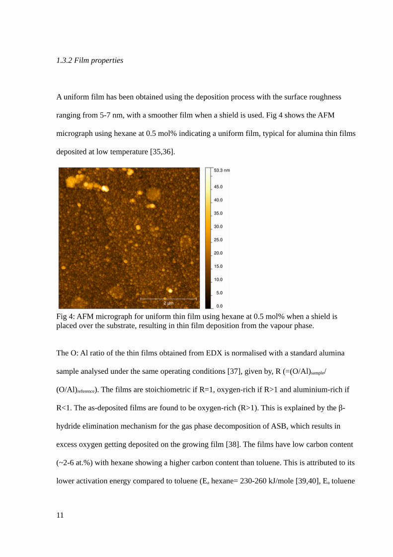
A uniform film has been obtained using the deposition process with the surface roughness
ranging from 5-7 nm, with a smoother film when a shield is used. Fig 4 shows the AFM
micrograph using hexane at 0.5 mol% indicating a uniform film, typical for alumina thin films
deposited at low temperature [35,36].
Fig 4: AFM micrograph for uniform thin film using hexane at 0.5 mol% when a shield is placed over the substrate, resulting in thin film deposition from the vapour phase.
The O: Al ratio of the thin films obtained from EDX is normalised with a standard alumina
sample analysed under the same operating conditions [37], given by, R (=(O/Al)sample/
(O/Al)reference). The films are stoichiometric if R=1, oxygen-rich if R>1 and aluminium-rich if
R<1. The as-deposited films are found to be oxygen-rich (R>1). This is explained by the β-
hydride elimination mechanism for the gas phase decomposition of ASB, which results in
excess oxygen getting deposited on the growing film [38]. The films have low carbon content
(~2-6 at.%) with hexane showing a higher carbon content than toluene. This is attributed to its
lower activation energy compared to toluene (Ea hexane= 230-260 kJ/mole [39,40], Ea toluene
11
= 293-335 kJ/mole [41–43]). This implies that hexane has a higher possibility to decompose
and deposit carbon in the growing film, particularly at the temperature used during the
deposition process (450-500oC). A part of the carbon may also come from the carbonyl
ligands of the precursor. The absence of any oxidants, such as water vapour, also assists in the
incorporation of the carbon in the growing film as there are no avenues for the removal of the
carbon from the system [44]. At the given deposition temperature, the carbon obtained are
expected to be aliphatic carbons where the carbon is attached to another carbon or hydrogen
bonds, which is as expected from the gas phase decomposition of ASB [38,45]. The presence
of the shield has no effect on the carbon content of the film.
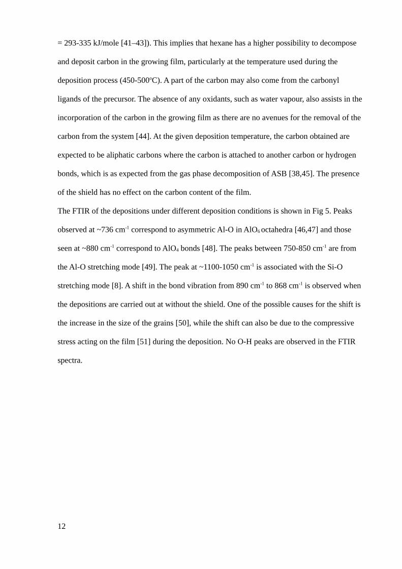
The FTIR of the depositions under different deposition conditions is shown in Fig 5. Peaks
observed at ~736 cm-1 correspond to asymmetric Al-O in AlO6 octahedra [46,47] and those
seen at ~880 cm-1 correspond to AlO4 bonds [48]. The peaks between 750-850 cm-1 are from
the Al-O stretching mode [49]. The peak at ~1100-1050 cm-1 is associated with the Si-O
stretching mode [8]. A shift in the bond vibration from 890 cm-1 to 868 cm-1 is observed when
the depositions are carried out at without the shield. One of the possible causes for the shift is
the increase in the size of the grains [50], while the shift can also be due to the compressive
stress acting on the film [51] during the deposition. No O-H peaks are observed in the FTIR
spectra.
12
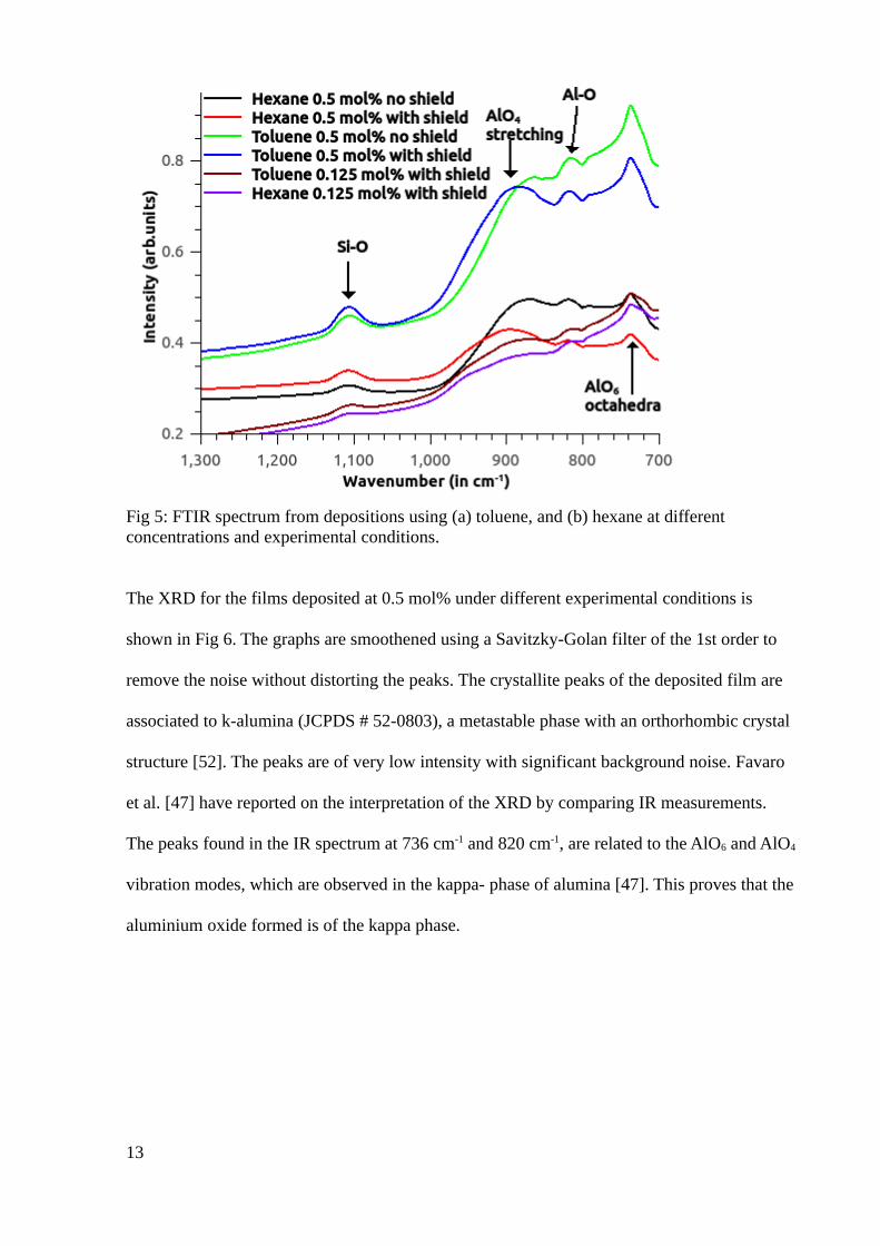
Fig 5: FTIR spectrum from depositions using (a) toluene, and (b) hexane at different concentrations and experimental conditions.
The XRD for the films deposited at 0.5 mol% under different experimental conditions is
shown in Fig 6. The graphs are smoothened using a Savitzky-Golan filter of the 1st order to
remove the noise without distorting the peaks. The crystallite peaks of the deposited film are
associated to k-alumina (JCPDS # 52-0803), a metastable phase with an orthorhombic crystal
structure [52]. The peaks are of very low intensity with significant background noise. Favaro
et al. [47] have reported on the interpretation of the XRD by comparing IR measurements.
The peaks found in the IR spectrum at 736 cm-1 and 820 cm-1, are related to the AlO6 and AlO4
vibration modes, which are observed in the kappa- phase of alumina [47]. This proves that the
aluminium oxide formed is of the kappa phase.
13
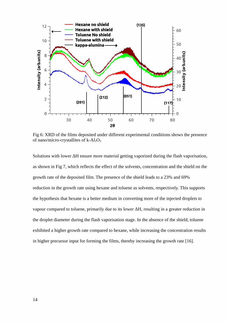
Fig 6: XRD of the films deposited under different experimental conditions shows the presenceof nano/micro-crystallites of k-Al2O3
Solutions with lower ΔH ensure more material getting vaporised during the flash vaporisation,
as shown in Fig 7, which reflects the effect of the solvents, concentration and the shield on the
growth rate of the deposited film. The presence of the shield leads to a 23% and 69%
reduction in the growth rate using hexane and toluene as solvents, respectively. This supports
the hypothesis that hexane is a better medium in converting more of the injected droplets to
vapour compared to toluene, primarily due to its lower ΔH, resulting in a greater reduction in
the droplet diameter during the flash vaporisation stage. In the absence of the shield, toluene
exhibited a higher growth rate compared to hexane, while increasing the concentration results
in higher precursor input for forming the films, thereby increasing the growth rate [16].
14
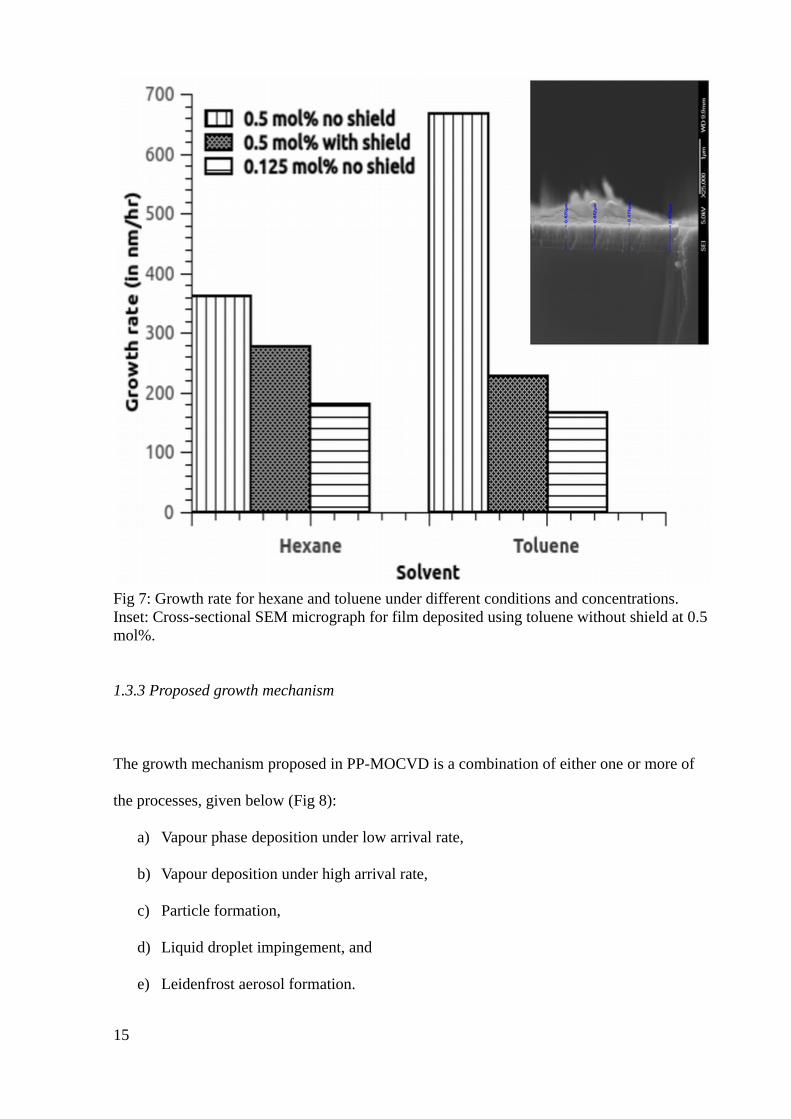
Fig 7: Growth rate for hexane and toluene under different conditions and concentrations. Inset: Cross-sectional SEM micrograph for film deposited using toluene without shield at 0.5 mol%.
1.3.3 Proposed growth mechanism
The growth mechanism proposed in PP-MOCVD is a combination of either one or more of
the processes, given below (Fig 8):
a) Vapour phase deposition under low arrival rate,
b) Vapour deposition under high arrival rate,
c) Particle formation,
d) Liquid droplet impingement, and
e) Leidenfrost aerosol formation.
15
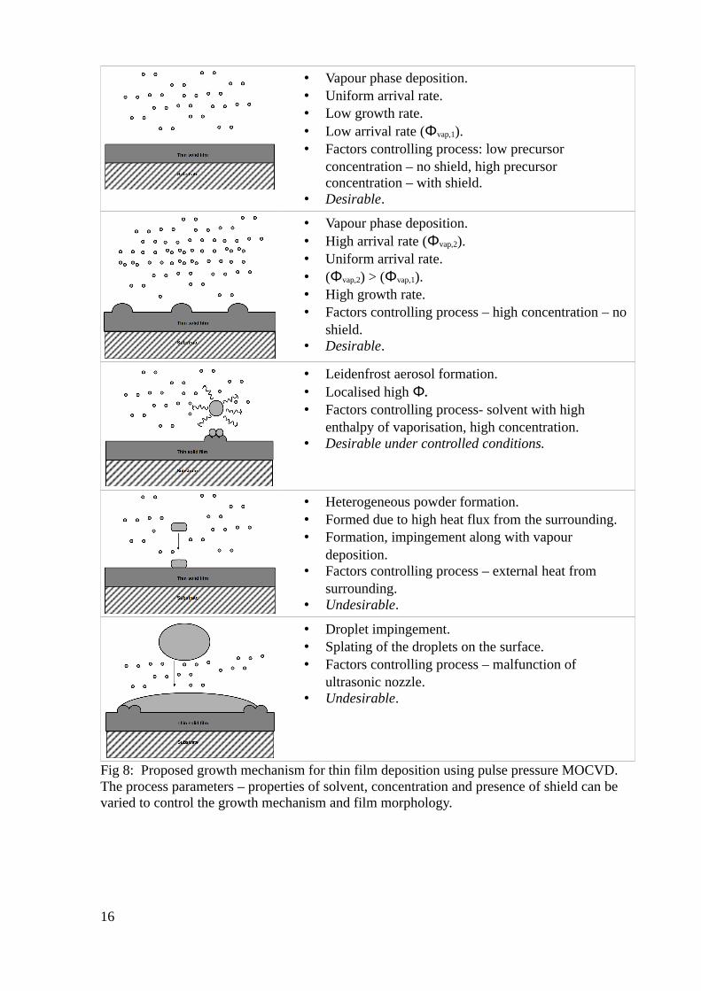
• Vapour phase deposition.• Uniform arrival rate.• Low growth rate.• Low arrival rate (Φvap,1).• Factors controlling process: low precursor
concentration – no shield, high precursor concentration – with shield.
• Desirable.
• Vapour phase deposition.• High arrival rate (Φvap,2).• Uniform arrival rate.• (Φvap,2) > (Φvap,1).• High growth rate.• Factors controlling process – high concentration – no
shield.• Desirable.
• Leidenfrost aerosol formation.• Localised high Φ.• Factors controlling process- solvent with high
enthalpy of vaporisation, high concentration.• Desirable under controlled conditions.
• Heterogeneous powder formation.• Formed due to high heat flux from the surrounding.• Formation, impingement along with vapour
deposition.• Factors controlling process – external heat from
surrounding.• Undesirable.
• Droplet impingement.• Splating of the droplets on the surface.• Factors controlling process – malfunction of
ultrasonic nozzle.• Undesirable.
Fig 8: Proposed growth mechanism for thin film deposition using pulse pressure MOCVD. The process parameters – properties of solvent, concentration and presence of shield can be varied to control the growth mechanism and film morphology.
16
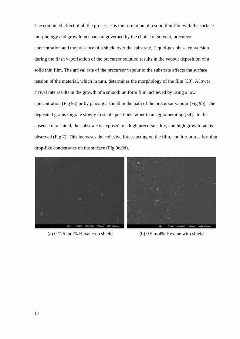
The combined effect of all the processes is the formation of a solid thin film with the surface
morphology and growth mechanism governed by the choice of solvent, precursor
concentration and the presence of a shield over the substrate. Liquid-gas phase conversion
during the flash vaporisation of the precursor solution results in the vapour deposition of a
solid thin film. The arrival rate of the precursor vapour to the substrate affects the surface
tension of the material, which in turn, determines the morphology of the film [53]. A lower
arrival rate results in the growth of a smooth uniform film, achieved by using a low
concentration (Fig 9a) or by placing a shield in the path of the precursor vapour (Fig 9b). The
deposited grains migrate slowly to stable positions rather than agglomerating [54]. In the
absence of a shield, the substrate is exposed to a high precursor flux, and high growth rate is
observed (Fig 7). This increases the cohesive forces acting on the film, and it ruptures forming
drop-like condensates on the surface (Fig 9c,9d).
(a) 0.125 mol% Hexane no shield (b) 0.5 mol% Hexane with shield
17
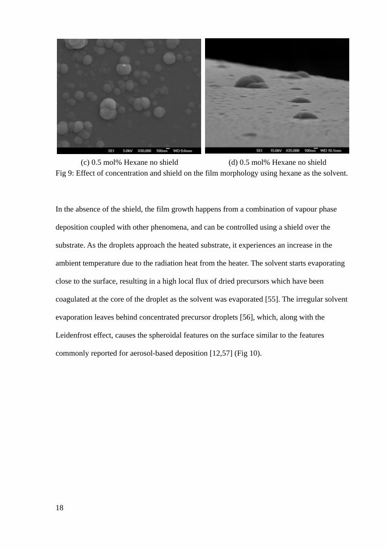
(c) 0.5 mol% Hexane no shield (d) 0.5 mol% Hexane no shieldFig 9: Effect of concentration and shield on the film morphology using hexane as the solvent.
In the absence of the shield, the film growth happens from a combination of vapour phase
deposition coupled with other phenomena, and can be controlled using a shield over the
substrate. As the droplets approach the heated substrate, it experiences an increase in the
ambient temperature due to the radiation heat from the heater. The solvent starts evaporating
close to the surface, resulting in a high local flux of dried precursors which have been
coagulated at the core of the droplet as the solvent was evaporated [55]. The irregular solvent
evaporation leaves behind concentrated precursor droplets [56], which, along with the
Leidenfrost effect, causes the spheroidal features on the surface similar to the features
commonly reported for aerosol-based deposition [12,57] (Fig 10).
18
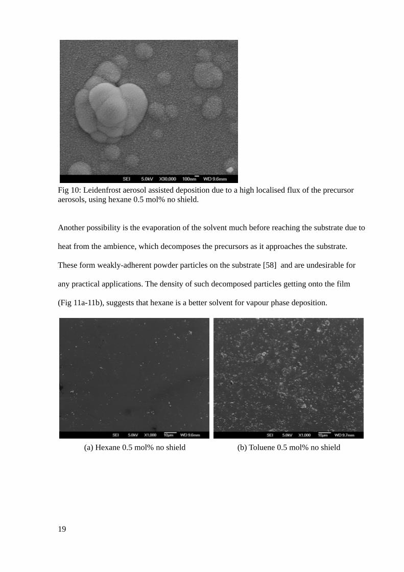
Fig 10: Leidenfrost aerosol assisted deposition due to a high localised flux of the precursor aerosols, using hexane 0.5 mol% no shield.
Another possibility is the evaporation of the solvent much before reaching the substrate due to
heat from the ambience, which decomposes the precursors as it approaches the substrate.
These form weakly-adherent powder particles on the substrate [58] and are undesirable for
any practical applications. The density of such decomposed particles getting onto the film
(Fig 11a-11b), suggests that hexane is a better solvent for vapour phase deposition.
(a) Hexane 0.5 mol% no shield (b) Toluene 0.5 mol% no shield
19
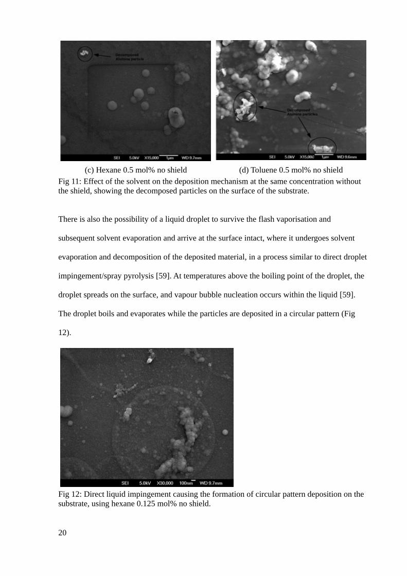
(c) Hexane 0.5 mol% no shield (d) Toluene 0.5 mol% no shieldFig 11: Effect of the solvent on the deposition mechanism at the same concentration without the shield, showing the decomposed particles on the surface of the substrate.
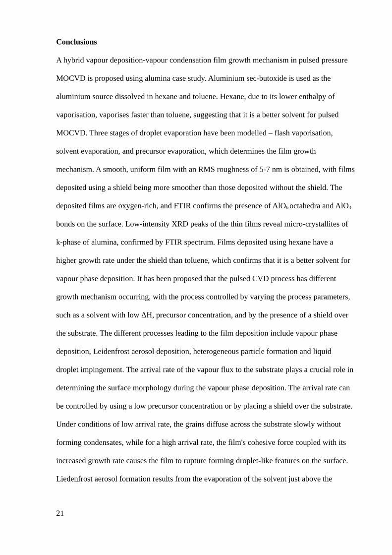
There is also the possibility of a liquid droplet to survive the flash vaporisation and
subsequent solvent evaporation and arrive at the surface intact, where it undergoes solvent
evaporation and decomposition of the deposited material, in a process similar to direct droplet
impingement/spray pyrolysis [59]. At temperatures above the boiling point of the droplet, the
droplet spreads on the surface, and vapour bubble nucleation occurs within the liquid [59].
The droplet boils and evaporates while the particles are deposited in a circular pattern (Fig
12).
Fig 12: Direct liquid impingement causing the formation of circular pattern deposition on the substrate, using hexane 0.125 mol% no shield.
20
Conclusions
A hybrid vapour deposition-vapour condensation film growth mechanism in pulsed pressure
MOCVD is proposed using alumina case study. Aluminium sec-butoxide is used as the
aluminium source dissolved in hexane and toluene. Hexane, due to its lower enthalpy of
vaporisation, vaporises faster than toluene, suggesting that it is a better solvent for pulsed
MOCVD. Three stages of droplet evaporation have been modelled – flash vaporisation,
solvent evaporation, and precursor evaporation, which determines the film growth
mechanism. A smooth, uniform film with an RMS roughness of 5-7 nm is obtained, with films
deposited using a shield being more smoother than those deposited without the shield. The
deposited films are oxygen-rich, and FTIR confirms the presence of AlO6 octahedra and AlO4
bonds on the surface. Low-intensity XRD peaks of the thin films reveal micro-crystallites of
k-phase of alumina, confirmed by FTIR spectrum. Films deposited using hexane have a
higher growth rate under the shield than toluene, which confirms that it is a better solvent for
vapour phase deposition. It has been proposed that the pulsed CVD process has different
growth mechanism occurring, with the process controlled by varying the process parameters,
such as a solvent with low ΔH, precursor concentration, and by the presence of a shield over
the substrate. The different processes leading to the film deposition include vapour phase
deposition, Leidenfrost aerosol deposition, heterogeneous particle formation and liquid
droplet impingement. The arrival rate of the vapour flux to the substrate plays a crucial role in
determining the surface morphology during the vapour phase deposition. The arrival rate can
be controlled by using a low precursor concentration or by placing a shield over the substrate.
Under conditions of low arrival rate, the grains diffuse across the substrate slowly without
forming condensates, while for a high arrival rate, the film's cohesive force coupled with its
increased growth rate causes the film to rupture forming droplet-like features on the surface.
Liedenfrost aerosol formation results from the evaporation of the solvent just above the
21

substrate resulting in a high localised vapour flux. External heat from the surroundings cause
the particles to decompose in the gas phase and land on the surface without contributing to the
film growth. Circular patterns are also found on the substrate due to the liquid impingement
on the substrate leaving the particles on the surface which gets decomposed while the solvent
gets evaporated. Vapour phase deposition and the Liedenfrost aerosol deposition are the
desired growth mechanisms, while the others processes are undesirable.
22
References
[1] V.A.C. Haanappel, H.D. Van Corbach, T. Fransen, P.J. Gellings, Corrosion resistant coatings ( A1203 ) produced by metal organic chemical vapour deposition using aluminium-tri-sec-butoxide, Thin Solid Films. 230 (1993) 138–144.
[2] J. Masalski, J. Gluszek, J. Zabrzeski, K. Nitsch, P. Gluszek, Improvement in corrosion resistance of the 316l stainless steel by means of Al 2 O 3 coatings deposited by the sol-gel method, Thin Solid Films. 349 (1999) 186–190.
[3] P. Vitanov, A. Harizanova, T. Ivanova, T. Dimitrova, Chemical deposition of Al2O3 thin films on Si substrates, Thin Solid Films. 517 (2009) 6327–6330. doi:10.1016/j.tsf.2009.02.085.
[4] J. Koo, S. Kim, S. Jeon, H. Jeon, Y. Kim, Characteristics of Al2O3 Thin Films Deposited Using Dimethylaluminum Isopropoxide and Trimethylaluminum Precursors by the Plasma-Enhanced Atomic-Layer Deposition Method, 48 (2006) 131–136.
[5] a. K. Chin, Al2O3 as an antireflection coating for InP/InGaAsP LEDs, J. Vac. Sci. Technol. B Microelectron. Nanom. Struct. 1 (1983) 72. doi:10.1116/1.582507.
[6] J. Echigoya, H. Enoki, RF magnetron sputtered aluminium oxide coatings on iridium, J. Mater. Sci. 31 (1996) 5247–5256.
[7] J. Gottmann, A. Husmann, T. Klotzbiicher, E.W. Kreutz, Optical properties of alumina and zirconia thin films grown by pulsed laser deposition, Eur. Phys. Journal. Appl. Phys. 101 (1998) 0–4. doi:10.1051/epjap/2013120530.
[8] S. Carmona-Tellez, J. Guzman-Mendoza, M. Aguilar-Frutis, G. Alarcon-Flores, M. Garcia-Hipolito, M. a. Canseco, C. Falcony, Electrical, optical, and structural characteristics of Al2O3 thin films prepared by pulsed ultrasonic sprayed pyrolysis, J. Appl. Phys. 103 (2008) 34105. doi:10.1063/1.2838467.
[9] M. Aguilar-frutis, M. Garcia, C. Falcony, G. Plesch, S. Jimenez-sandoval, A study of the dielectric characteristics of aluminum oxide thin films deposited by spray pyrolysis from Al(acac)3, Thin Solid Films. 389 (2001) 200–206.
[10] B.P. Dhonge, T. Mathews, S.T. Sundari, C. Thinaharan, M. Kamruddin, S. Dash, a. K. Tyagi, Spray pyrolytic deposition of transparent aluminum oxide (Al 2O3) films, Appl. Surf. Sci. 258 (2011) 1091–1096. doi:10.1016/j.apsusc.2011.09.040.
[11] J.C. Ortiz, A, Alonso, High quality-low temperature aluminum oxide films deposited by ultrasonic spray pyrolysis, J. Mater. Sci. Mater. Electron. 13 (2002) 7–11.
[12] Y. Wu, K.-L. Choy, The microstructure of alumina coatings prepared by aerosol assisted spray deposition, Surf. Coatings Technol. 180–181 (2004) 436–440. doi:10.1016/j.surfcoat.2003.10.078.
23
[13] T. Maruyama, S. Arai, Aluminum oxide thin films prepared from aluminum acetylacetonate by chemical vapor deposition, Appl. Phys. Lett. 60 (1992) 322–323.
[14] P. Marchand, I. a Hassan, I.P. Parkin, C.J. Carmalt, Aerosol-assisted delivery of precursors for chemical vapour deposition: expanding the scope of CVD for materials fabrication., Dalton Trans. 42 (2013) 9406–22. doi:10.1039/c3dt50607j.
[15] P.-L. Etchepare, L. Baggetto, H. Vergnes, D. Samélor, D. Sadowski, B. Caussat, C. Vahlas, Process-structure-properties relationship in direct liquid injection chemical vapor deposition of amorphous alumina from aluminum tri-isopropoxide, Phys. Status Solidi. 12 (2015) 944–952. doi:10.1002/pssc.201510037.
[16] S.P. Krumdieck, B.P. Reyngoud, A.D. Barnett, D.J. Clearwater, R.M. Hartshorn, C.M. Bishop, B.P. Redwood, E.L. Palmer, Deposition of Bio-Integration Ceramic Hydroxyapatite by Pulsed-Pressure MOCVD Using a Single Liquid Precursor Solution,Chem. Vap. Depos. 16 (2010) 55–63. doi:10.1002/cvde.200906839.
[17] S.P. Krumdieck, O. Sbaizero, A. Bullert, R. Raj, YSZ layers by pulsed-MOCVD on solid oxide fuel cell electrodes, Surf. Coatings Technol. 167 (2003) 226–233. doi:10.1016/S0257-8972(02)00908-8.
[18] C.W. Lim, H. Cave, M. Jermy, S. Krumdieck, Liquid Droplet Evaporation in Simulations of the Flow in Pulsed-Pressure MOCVD, ECS Trans. (2009) 1251–1258. doi:10.1149/1.3207730.
[19] S. Krumdieck, A. Kristinsdottir, L. Ramirez, M. Lebedev, N. Long, Growth rate , microstructure and conformality as a function of vapor exposure for zirconia thin films by pulsed-pressure MOCVD, Surf. Coatings Technol. 201 (2007) 8908–8913. doi:10.1016/j.surfcoat.2007.03.009.
[20] D. Lee, S. Krumdieck, S.D. Talwar, Scale-up design for industrial development of a PP-MOCVD coating system, Surf. Coatings Technol. 230 (2013) 39–45. doi:10.1016/j.surfcoat.2013.06.064.
[21] R. Boichot, S. Krumdieck, Numerical Modeling of the Droplet Vaporization for Designand Operation of Liquid-pulsed CVD, Chem. Vap. Depos. 21 (2015) 1–10. doi:10.1002/cvde.201507191.
[22] G. V. Jayanthi, S.C. Zhang, G.L. Messing, Modeling of Solid Particle Formation During Solution Aerosol Thermolysis: The Evaporation Stage, Aerosol Sci. Technol. 19(1993) 478–490. doi:10.1080/02786829308959653.
[23] N.R. Gunby, S. Krumdieck, H. Murthy, S.L. Masters, S.S. Miya, Study of precursor chemistry and solvent systems in pp-MOCVD processing with alumina case study, Phys. Status Solidi. 212 (2013) 1–8. doi:10.1002/pssa.201532309.
24
[24] A. V. Osipov, Kinetic model of vapour-deposited thin film condensation: stage of liquid-like coalescence, Thin Solid Films. 261 (1995) 173–182. doi:10.1016/S0040-6090(94)06486-5.
[25] L.H. Chen, C.Y. Chen, Y.L. Lee, Nucleation and growth of clusters in the process of vapor deposition, Surf. Sci. 429 (1999) 150–160. doi:10.1016/S0039-6028(99)00360-X.
[26] S. Hashmi, Comprehensive materials processing, Newnes, 2014.
[27] Z. Chen, S. Li, Z. Liu, Morphology and growth mechanism of CVD alumina – silica, Ceram. Int. 31 (2005) 1103–1107. doi:10.1016/j.ceramint.2004.12.003.
[28] Y. Xu, L. Cheng, L. Zhang, W. Zhou, Morphology and growth mechanism of silicon carbide chemical vapor deposited at low temperatures and normal atmosphere, J. Mater. Sci. 4 (1999) 551–555.
[29] Q. Sheng, J. Sun, Q. Wang, W. Wang, H.S. Wang, On the onset of surface condensation: formation and transition mechanisms of condensation mode, Sci. Rep. 6 (2016).
[30] L. Tianqing, M. Chunfeng, S. Xiangyu, X. Songbai, Mechanism Study on Formation ofInitial Condensate Droplets, Am. Inst. Chem. Eng. 53 (2007) 1–6. doi:10.1002/aic.
[31] Y.L. Lee, J.R. Maa, Nucleation and growth of condensate clusters on solid surfaces, J. Mater. Sci. 26 (1991) 6068–6072. doi:10.1007/BF01113885.
[32] S.K. Basant Singh Sikarwar , Sameer Khandekar , Smita Agrawal, K. Muralidhar, Dropwise Condensation Studies on Multiple Scales, Heat Transf. Eng. 33 (2012) 301–341. doi:10.1080/01457632.2012.611463.
[33] I. Gutzow, I. Avramov, The mechanism of formation, the structure and the properties ofamorphous films, Thin Solid Films. 85 (1981) 203–221.
[34] V. Siriwongrungson, M.M. Alkaisi, S.P. Krumdieck, Step coverage of thin titania films on patterned silicon substrate by pulsed-pressure MOCVD, Surf. Coatings Technol. 201 (2007) 8944–8949. doi:10.1016/j.surfcoat.2007.03.051.
[35] S. Blittersdorf, N. Bahlawane, K. Kohse-Höinghaus, B. Atakan, J. Müller, CVD of Al2O3 Thin Films Using Aluminum Tri-isopropoxide, Chem. Vap. Depos. 9 (2003) 194–198. doi:10.1002/cvde.200306248.
[36] A. Ito, R. Tu, T. Goto, Amorphous-like nanocrystalline gamma-Al2O3 films prepared by MOCVD, Surf. Coatings Technol. 204 (2010) 2170–2174. doi:10.1016/j.surfcoat.2009.11.043.
[37] A.N. Gleizes, C. Vahlas, M.M. Sovar, D. Samélor, M.C. Lafont, CVD-fabricated aluminum oxide coatings from aluminum tri-iso-propoxide: Correlation between
25
processing conditions and composition, Chem. Vap. Depos. 13 (2007) 23–29. doi:10.1002/cvde.200606532.
[38] H.D. Van Corbach, T. Fransen, P.J. Gellings, The pyrolytic decomposition of aluminium-tri- sec-butoxide during chemical vapour deposition of thin alumina films, Thermochim. Acta. 240 (1994) 67–77.
[39] K.H. Ebert, H.J. Ederer, G. Isbarn, The thermal decomposition of n-hexane, Int. J. Chem. Kinet. 15 (1983) 475–502. doi:10.1002/kin.550150508.
[40] R.. Partington, C.. Danby, The thermal decomposition of n-hexane, J. Chem. Soc. (1948) 2226–2232.
[41] M. Szwarc, The C–H Bond Energy in Toluene and Xylenes, J. Chem. Phys. 128 (2002).doi:10.1063/1.1746794.
[42] R. Sivaramakrishnan, R.S. Tranter, and K. Brezinsky*, High Pressure Pyrolysis of Toluene. 1. Experiments and Modeling of Toluene Decomposition, J. Phys. Chem. A. 110 (2006) 9388–9399. doi:10.1021/jp060820j.
[43] S.J. Price, The pyrolysis of toluene, Can. J. Chem. 10 (1962).
[44] J. Kim, H.A. Marzouk, P.J. Reucroft, J.D. Robertson, C.E. Hamrin, Effect of water vapor on the growth of aluminum oxide films by low pressure chemical vapor deposition, Thin Solid Films. 230 (1993) 156–159.
[45] H. Gong, M.P. Singh, S.A. Shivashankar, T. Shripathi, K. Road, A STUDY OF ALUMINA THIN FILMS GROWN BY LOW PRESSURE MOCVD: XPS AND AES, Int. J. Mod. Phys. B. 16 (2002) 1261–1267.
[46] G. Ji, M. Li, G. Li, G. Gao, H. Zou, S. Gan, X. Xu, Hydrothermal synthesis of hierarchical micron flower-like γ-AlOOH and γ-Al2O3 superstructures from oil shale ash, Powder Technol. 215–216 (2012) 54–58. doi:10.1016/j.powtec.2011.09.005.
[47] G. Sattonnay, Experimental and ab initio infrared study of χ - , κ - and α -aluminas formed from gibbsite, J. Solid State Chem. 183 (2010) 901–908. doi:10.1016/j.jssc.2010.02.010.
[48] G. Sattonnay, J.B. Brubach, P. Berthet, A. Boumaza, L. Favaro, J. Le, A.M. Huntz, P. Roy, R. Te, Transition alumina phases induced by heat treatment of boehmite : An X - ray diffraction and infrared spectroscopy study, J. Solid State Chem. 182 (2009) 1171–1176. doi:10.1016/j.jssc.2009.02.006.
[49] X. Multone, High Vacuum Chemical Vapor Deposition ( HV-CVD ) of Alumina Thin Films, 2009.
[50] S. Kurien, ANALYSIS OF FTIR SPECTRA OF NANOPARTICLES of MgAl2O4, SrAl2O4, and NiAl2O4, 1595 (2005) 64–78. http://mgutheses.in/page/?q=T 1354&search=siby+kurien&page=1&rad=sc.
26

[51] K. Sowri Babu, A.R. Reddy, C. Sujatha, K.V. Reddy, A.N. Mallika, Synthesis and optical characterization of porous ZnO, J. Adv. Ceram. 2 (2013) 260–265. doi:10.1007/s40145-013-0069-6.
[52] M. Halvarsson, J.E. Trancik, S. Ruppi, The microstructure of CVD k-Al2O3 multilayers separated by thin intermediate TiN or TiC layers, Int. J. Refract. Met. Hard Mater. 24 (2006) 32–38. doi:10.1016/j.ijrmhm.2005.06.007.
[53] D. Vick, L.J. Friedrich, S.K. Dew, M.J. Brett, K. Robbie, M. Seto, T. Smy, Self-shadowing and surface diffusion effects in obliquely deposited thin films, Thin Solid Films. 339 (1999) 88–94. doi:10.1016/S0040-6090(98)01154-7.
[54] X.J. Qin, L. Zhao, G.J. Shao, N. Wang, Influence of solvents on deposition mechanism of Al-doped ZnO films synthesized by cold wall aerosol-assisted chemical vapor deposition, Thin Solid Films. 542 (2013) 144–149. doi:10.1016/j.tsf.2013.07.002.
[55] A. Gurav, T. Kodas, T. Pluym, Y. Xiong, Aerosol Processing of Materials, Aerosol Sci. Technol. 19 (1993) 411–452. doi:10.1080/02786829308959650.
[56] S. Krumdieck, S. Davies, C.M. Bishop, T. Kemmitt, J.V. Kennedy, Al2O3 coatings on stainless steel using pulsed-pressure MOCVD, Surf. Coatings Technol. 230 (2013) 208–212. doi:10.1016/j.surfcoat.2013.06.119.
[57] M.I. Martín, L.S. Gómez, O. Milosevic, M.E. Rabanal, Nanostructured alumina particles synthesized by the Spray Pyrolysis method: microstructural and morphological analyses, Ceram. Int. 36 (2010) 767–772. doi:10.1016/j.ceramint.2009.10.013.
[58] M. Khalid, M. Mujahid, A.N. Khan, R.S. Rawat, I. Salam, K. Mehmood, Plasma Sprayed Alumina Coating on Ti6Al4V Alloy for Orthopaedic Implants: Microstructure and Phase Analysis, Key Eng. Mater. 510–511 (2012) 547–553. doi:10.4028/www.scientific.net/KEM.510-511.547.
[59] U.P. Muecke, G.L. Messing, L.J. Gauckler, The Leidenfrost effect during spray pyrolysis of nickel oxide-gadolinia doped ceria composite thin films, Thin Solid Films. 517 (2009) 1515–1521. doi:10.1016/j.tsf.2008.08.158.
27