Embed Size (px)
Citation preview
1
STUDY REPORT ON ENHANCING ELECTRICAL SAFETY
FOR 230 V DOMESTIC SUPPLY ONBOARD EXISTING AND NEW
CONSTRUCTION SHIPS
IHQ MOD (N)/DEENEW DELHI
Document Reference : EED-50-07Date : Aug 06
2
INDEX
CHAPTER TITLE PAGE NO1 Abstract 1
2 Study of Electrical Shock and Naval Standards 23 Study on Domestic Supply System Arrangement
onboard Existing Platforms7
4 Field Study – Indigenous Ships 9
5 Domestic Supply System on New Construction Ships
13
6 Conclusion and Recommendations 15
3
APPENDICES
APPENDIX TITLE PAGE NOA Study Electric shock & protection circuit Design 17
B Relevant Extract of Def Stan 615 Part 4/1
27
C Relevant extract of NES 539 31
D Existing design and distribution arrangement of 230V 50 Hz 1 phase power supply – INS Investigator
34
E Proposal for retrofitment of 4 wire power supply distribution system for 230 V 1 phase onboard INS Investigator
37
F Existing design and distribution arrangement of 230V 50 Hz 1 phase power supply – INS Godavari
42
G Proposal for retrofitment of 4 wire power supply distribution system for 230 V 1 phase onboard INS Godavari
44
H Recommended 4 wire domestic distribution system as modification.
48
J Proposed OnLine Insulation Monitoring System onboard INS Godavari and Investigator
49

4
5
CHAPTER 1
ABSTRACT
1.1 Background. A study has been undertaken by the Directorate of Electrical Engineering with regard to the distribution circuits of the 220 volts domestic supplies on board Naval Ships.
1.2 Factors Influencing Shock Level. Contrary to the popular belief, the level of voltage is not directly proportional to the level of injury or danger of death. For a given operating voltage, it is the amplitude and period of current flow through the body which decide the level of electric shock. This current can be limited to safe levels by increasing the resistance of the body and by designing the safety circuits so as to be capable of detecting earth leakage conditions and tripping supplies in shortest possible time.
1.3 Existing Standards for Domestic Supply. NES 539 (Guide to the Design of Supply System for Portable Electrical Equipment) and Def Stan 615 Part 4 (Electrical Power Supply Systems below 650 volts Part 4: Power supply in HM ships) specify a 3 Ph 3 wire power distribution system with a floating neutral for consumers of primary supply and domestic lighting so as to provide earth leakage fault resistant operation. These standards also envisage a converted supply of 230 V 3 Phase 4 wire distribution system from a step down transformer with neutral grounded for the domestic system to reduce the catastrophic effect of electric shock at 230 volts.
1.4 During the initial indigenous ship Construction certain ships of IN, the domestic supplies onboard were drawn from a 3 phase, 3 wire system with floating neutral. The supplies were tapped between phase to phase (115V) with a “double pole double throw” switch for switching on/off the supplies. Such an arrangement meant that the phase to earth voltage was 57.5 volts which incase of a phase to earth fault is considered to be safe with reduced shock level voltage and thereby ensuring that incase of shock, the consequence is not lethal. Similar arrangements were in place on board Russian origin ships. The only difference being that the phase to phase voltage in this case was 127 volts. The domestic equipment in those times were specially designed for onboard use and operated on 127/115 volts. With the induction of commercial domestic equipment for onboard use, a 230 volts domestic distribution arrangement was adopted in indeginous ship construction project. This changed scheme, however, had a flaw in that, instead of 4 wire system, as specified in NES, the design adopted 3 wire system and therefore did not meet the safety standards.
1.5 Field Study. In this phase, survey of power distribution for domestic supply was undertaken onboard certain IN ships. It was established that 230 V domestic supply system was drawn from a 3 phase 3 wire system which could be modified to a
6
4 wire system conforming to the safety aspects of NES 539. The modification involves conversion to a 4 wire system by running local cables and installation of appropriate transformers and “Double pole Double throw” switches. The efficacy of off line insulation measuring device fitted on switchboards of exiting ships was also studied and found unsatisfactory as they do not continuously monitor the insulation and also have no provision of visual fault indication. Therefore, their replacement with on line insulation monitoring devices is also considered essential.
1.6 Conclusion. The 230 volts power supply distribution circuits for systems/equipment onboard warships must conform to NES 539 and provide fault resistant supplies to mission critical equipment . At the same time, It should also provide a safe domestic supply circuit. The first requirement is met by implementing a 3 phase 3 wire system with the floating neutral where as implementation of a 3 phase 4 wire system with earthed neutral and fitted with earth leakage protection breakers for the domestic supplies fulfils the second requirement. The specifications for such circuits is specified in NES 539. Further, the installation of on line insulation monitoring devices would facilitate continous monitoring of insulation.
7
Way Ahead
1.7 Recommendations. There is a need to enhance the inherent safety features in the domestic 230 V circuit. This can be done progressively in stages and to be completed by the next refit of the ships. Following is recommended:
(a) Ships in Commission. The ships in commission need to implement the following:
(i) Change of “Single pole” commercial switches to “Double pole Double throw” switches throughout the domestic supply circuits.
(ii) Modification of galley, pantry and wet compartment supplies to a 4 wire system as indicated at Para 1.5 above.
(iii) Incorporation of on line earth fault detection system at switchboards.
(b) New Construction Ships. The domestic supply circuits in new induction ships to be modified so as to conform to NES 539 with simultaneous installation of online earth fault detection system at switchboards.
8
CHAPTER 2
STUDY OF ELECTRICAL SHOCK AND NAVAL STANDARDS
Electric Shock
2.1 An electric shock can occur upon contact of a human with any source of voltage high enough to cause sufficient current flow through the muscles or nerves. The minimum detectable current in human body is thought to be about 1 milliampere(mA). The current may cause tissue damage or heart fibrillation if it is sufficiently high. When an electric shock is fatal, it is called electrocution. The study of Electric shock carried out from various standards and public domain literature is placed at Appendix A.
2.2 An electric shock is usually painful and can be lethal. Contrary to the popular belief, the level of voltage is not a direct guide to the level of injury or danger of death. A small shock from static electricity may contain thousands of volts but has very little current behind it due to high internal resistance. The effect of the electric shock is generally determined by current and the duration of its flow through the body. Even a low voltage causing a current of extended duration can be fatal.
2.3 Factors Affecting Lethality. In addition to magnitude and duration of current flowing through the human body, other factors contributing to the same are discussed in succeeding paragraphs.
(a) Frequency. The comparison between the dangers of Alternating Current (AC) and Direct Current (DC) has always been a subject of debate. The DC tends to cause continuous muscular contractions that make the victim hold on to a live conductor, thereby increasing the risk of deep tissue burns. On the other hand, AC tends to interfere more with the heart's electrical pacemaker, leading to an increased risk of fibrillation. Also, AC at higher frequencies causes RF burns and tissue damage. Generally, higher frequency AC current tends to run along the skin rather than penetrating and touching vital organs such as the heart. While there will be severe burn damages at higher voltages, they are normally not fatal.
(b) Voltage. It is believed that human lethality is most common with AC current between 100250 volts. This is so because voltages lower than these usually fail to overcome body resistance where as at higher voltages the victim's muscular contractions are often severe enough to cause them to recoil and get detatched from the exposed electrical circuit. However, deaths have occurred from supplies as low as 32 volts also.
(c) Body Resistance. The resistance of a human body varies from part to part. The resistance between major extremities of an average human body
9
from hand to hand, or hand to foot is about 1500 ohms. This drops down to 300 ohms when the body is moist and may even become zero when there are breaks in the skin. For a given voltage, lower the body resistance higher is the current flow and so is the consequent lethality.
(d) Current Flow Path. The two most dangerous paths that current can take through the body are from hand to hand and from left hand to either foot. The latter is the most dangerous as in this case the current flows through the heart and vital organs.
(e) Current Magnitude and Duration. A lowvoltage (110 to 230 V), 60Hz AC current traveling through the chest for a fraction of a second may induce ventricular fibrillation at currents as low as 60mA. With DC, this value increases to 300 to 500 mA. Fibrillations are usually lethal because the heart muscle cells move independently. Above 200mA, muscle contractions are so strong that the heart muscles cannot move leading to cardiac arrest.
2.4 The discussions in the preceding paragraphs amplify the fact that the fatality due electrocution is a function of current flow and its duration through the body. For a given voltage, the amplitude of current through the body can be limited by increasing the resistance of the body by use of insulating shoes and adherence to safe electrical practices. In addition, the safety circuits on board must be capable of detecting earth leakage conditions and tripping supplies in shortest possible time. The table at Para 6 of Appendix A gives the guiding parameters for implementation of protection circuits.
Design Standards on Distribution Systems
2.5 The power supply arrangement onboard a Naval ship are governed by Def Stan 615 Part 4 (Electrical Power Supply Systems below 650 volts Part 4: Power supply in HM ships) (Appendix B). NES 539 (Guide to the design of supply system for portable electrical equipment) (Appendix C) and While these standards lay down norms for quality of power supply, they also specify that the ship’s primary supply will be 3phase, 3 wire unearthed (neutral floating) configuration. Use of single phase supply is restricted for lighting, domestic appliances and test equipment. The documents specify the following for the power distribution system:
(i) Main Supply. The ships main power supply will be 440V/415V/380V 60/50Hz, 3 phase unearthed and all the converted power supplies AC/DC (eg 115V, 1ph, 24 V DC)will be derived from the main supply.
(ii) Floating Neutral. The main power supply will be unearthed so that important services are not automatically disconnected by their protection circuits under an earth leakage condition.
10
(iii) Converted/Domestic Supply. To reduce the shock risk to personnel, the converted supply 115 Volts shall be derived using 440 V /115 V 3 phase transformers having three isolated single phase secondary windings, each winding will be centre tapped and solidly earthed at its mid point. Thus, the line voltage is restricted to a maximum of 57.5 V above earth. Any earth fault will cause the fuses in the circuit to rupture.
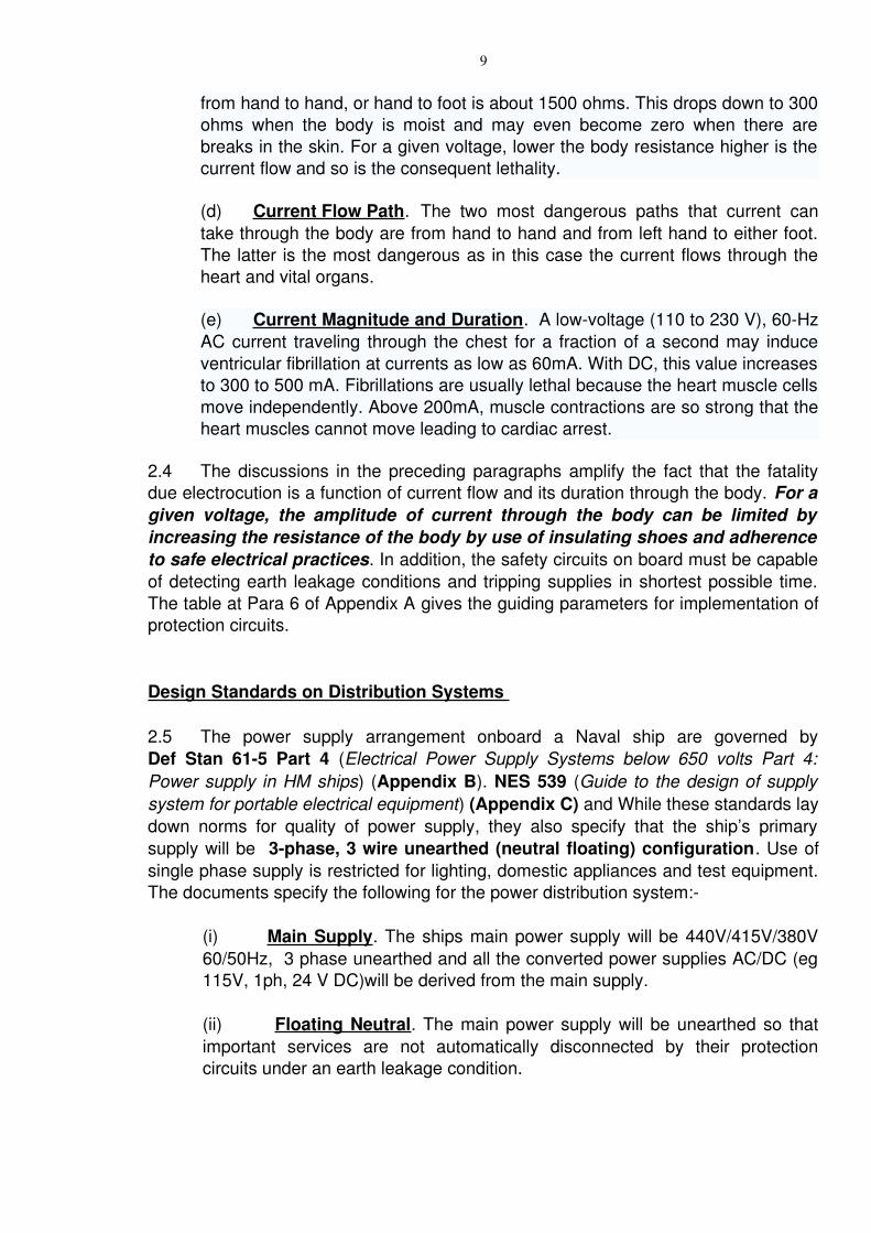
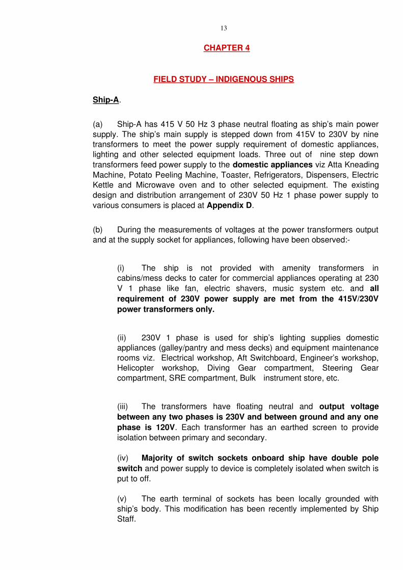
2.6 Recommended 230 Volts Domestic Distribution System. NES 539 recommends a 3 phase, 4 wire, 230 volts, systems with neutral earthed. This system is to be derived from the primary 3 phase 3 wire system with floating neutral employing a star star transformer. In addition, to providing increased safety for domestic consumer such an arrangement isolates the mission critical 415/380 volts, 3 phase primary distribution circuits from the domestic 230 volts circuits. The schematic diagram for derived 230 volts, 3 phase, 4 wire system is shown in Fig 1.
SECONDARY OF TRANSFORMER
BODY OF TRANSFORMER
Fig 1 – 230 Volts 3 Phase 4 Wire System
2.7 The above distribution system incorporates additional safety to personnel operating commercial electric appliances on domestic 230 volts circuits. The transformer feeding the domestic loads in this case has an earthed neutral implying that the potential on the neutral is zero. The single phase supplies in this system are taken between phase and neutral instead of phases to phase as in case of 3 wire system. In addition, the earth wire running to all the supply sockets provides for grounding of supplies in case of an accidental short of the phase with the body of the appliance. Further, use of Earth Leakge Circuit Breaker (ELCB) provides further protection against faults supply circuits.
11
CHAPTER 3
STUDY ON DOMESTIC SUPPLY ARRANGEMENT ONBOARD EXISTING PLATFORMS
3.1 Domestic Supply SystemsIndigenous Ship Construction. The domestic supplies onboard the earlier indigenous construction ships was 3 phase, 3 wire 115 volts. The domestic supplies were tapped between phase to phase with a “double pole double throw” switch for switching on/off the supplies. Such an arrangement meant that the phase to earth voltage was 57.5 volts which in case of a phase to earth fault is considered non life threatening. Similar arrangements were in place on board Russian origin ships using 127 volts. The domestic equipment at that time were specially designed for on board use and operated on 115 volts (127 V for Russian origin ships).
3.2 NonAdherence to Ship Building Standards in Subsequent Indigenous Ships. The above practise changed with the induction of commercial domestic equipment for onboard use. As these equipment operated on 230 volts, there was a need to provide a 230 volts domestic distribution circuit. The arrangement was implemented in two different manners on board indigenous ships.
(a) Upto Project 16. The indigenous ships till Project 16 have a 115 volts, 60 hz, 1 phase power supply for lighting and portable equipment. The commercial/domestic equipment have been provided with 230 volts, 60 hz, 1 phase supply using power transformers with floating neutral. This arrangement does not conform to the to NES Specifications as brought out in Para 2.6 above. Use of single pole single throw switches added to the reduced safety as despite the supplies being switched off, one phase was always available at the equipment/socket. The equipment earthing, in this case, also did not provide the required safety level.
(b) Project 25 Onwards. By this time, with the induction of COTs equipment for specific military applications, Indian Navy did away with the use of 115V, 1 phase supply. The use of 230V phase to phase was extended to all onboard applications including portable and domestic lighting. However, these supplies too were derived from a three wire unearthed system and thereby not conforming to the NES 539 Specifications. Use of “Single pole Single throw” switches further contributed to the reduced safety.
3.3 Domestic and Lighting Supply in Russian Origin Ships . The power supply and distribution system onboard the Russian origin ships is as follows:
(a) SNF Class of Ships. The main supply onboard the certain IN ships is 380 V 3 Ph 50 Hz with neutral floating. This supply is stepped down to 127 V, 3 Ph through ∆ || Ү transformers and is made available to the galley
12
equipment though distribution breakers. The domestic lighting is also 127 V 1 Ph. Portable 127 V to 230 V transformers were provided for operation of commercial equipment. As the supplies are tapped between phase to phase, “Double pole Double throw” switches are used. Post series of modifications, a dedicated 230 volts supply circuit through 380 to 230 volts step down transformers has been provided.
(b) Ship of class A. The main supply onboard SNM class of ships 380 V 3Ph 50 Hz with neutral floating. This is stepped down to 230 V, 3 Ph through stepped down ∆||∆ transformers for the galley equipment. This system also employs a floating neutral concept.
(c) Ship of class B. The class B ships employ 230 volts for galley as well as domestic lighting. The ship wide 230 volt supplies are derived through two 380/230 volts transformers. The 230 volts circuits on board these ships are 3 wire with floating neutral. Double pole double throw switches are used through out the ship on all circuits.
13
CHAPTER 4
FIELD STUDY – INDIGENOUS SHIPS
ShipA.
(a) ShipA has 415 V 50 Hz 3 phase neutral floating as ship’s main power supply. The ship’s main supply is stepped down from 415V to 230V by nine transformers to meet the power supply requirement of domestic appliances, lighting and other selected equipment loads. Three out of nine step down transformers feed power supply to the domestic appliances viz Atta Kneading Machine, Potato Peeling Machine, Toaster, Refrigerators, Dispensers, Electric Kettle and Microwave oven and to other selected equipment. The existing design and distribution arrangement of 230V 50 Hz 1 phase power supply to various consumers is placed at Appendix D.
(b) During the measurements of voltages at the power transformers output and at the supply socket for appliances, following have been observed:
(i) The ship is not provided with amenity transformers in cabins/mess decks to cater for commercial appliances operating at 230 V 1 phase like fan, electric shavers, music system etc. and all requirement of 230V power supply are met from the 415V/230V power transformers only.
(ii) 230V 1 phase is used for ship’s lighting supplies domestic appliances (galley/pantry and mess decks) and equipment maintenance rooms viz. Electrical workshop, Aft Switchboard, Engineer’s workshop, Helicopter workshop, Diving Gear compartment, Steering Gear compartment, SRE compartment, Bulk instrument store, etc.
(iii) The transformers have floating neutral and output voltage between any two phases is 230V and between ground and any one phase is 120V. Each transformer has an earthed screen to provide isolation between primary and secondary.
(iv) Majority of switch sockets onboard ship have double pole switch and power supply to device is completely isolated when switch is put to off.
(v) The earth terminal of sockets has been locally grounded with ship’s body. This modification has been recently implemented by Ship Staff.
14
(c) Proposed retrofitment scheme for 4 wire power supply distribution system for 230 V 1 phase onboard INS Investigator is placed at Appendix E.
Ship B
(d) ShipB has 440V 60 Hz 3 phase neutral floating as ship’s main power supply. The ship is fitted with five 440V/230V transformers which meet the power supply requirement of domestic and other select equipment loads. The lighting supply onboard ship is 115V 60Hz 1 phase. The design of transformers and distribution of 230V 60 Hz 1 phase power supply to various consumers is placed at Appendix F.
(e) During the measurements of voltages at the power transformer outputs and at the supply sockets for appliances, following have been observed:
(i) All the above transformers with exception of the amenity transformers have floating neutral. The amenity transformer however has its secondary neutral grounded.
(ii) The existing 230V 60 Hz 1 phase power supplies are drawn from a 3 wire system with neutral floating. Further, the earth point in all the domestic sockets is floating. These sockets also use single pole switch.
(iii) Both the phase/neutral points in all the sockets are live even with the switch being in ‘OFF’ condition. Being single pole, the switch isolates only one phase and not both.
(iv) Absence of an earth raises the risk of electric shock to personnel.
(v) There are small 115V/230V amenity transformers in each cabin for catering to amenity loads like electric shavers, etc.
(vi) During the study, measurement of voltages was carried out on the transformers and domestic sockets in Sailors’ Galley, Officers’ Galley, Wardroom and the observations are as follows:
(aa) The output voltages (RGnd, YGnd, BGnd, RY, YB and BR) on the transformers (the phasetophase and phasetoground (hull) voltage was measured and are as follows:
• RY = 230V• YB = 230V• BR = 230V
15
• RGnd = 115V• YGnd = 115V• GGnd = 115V
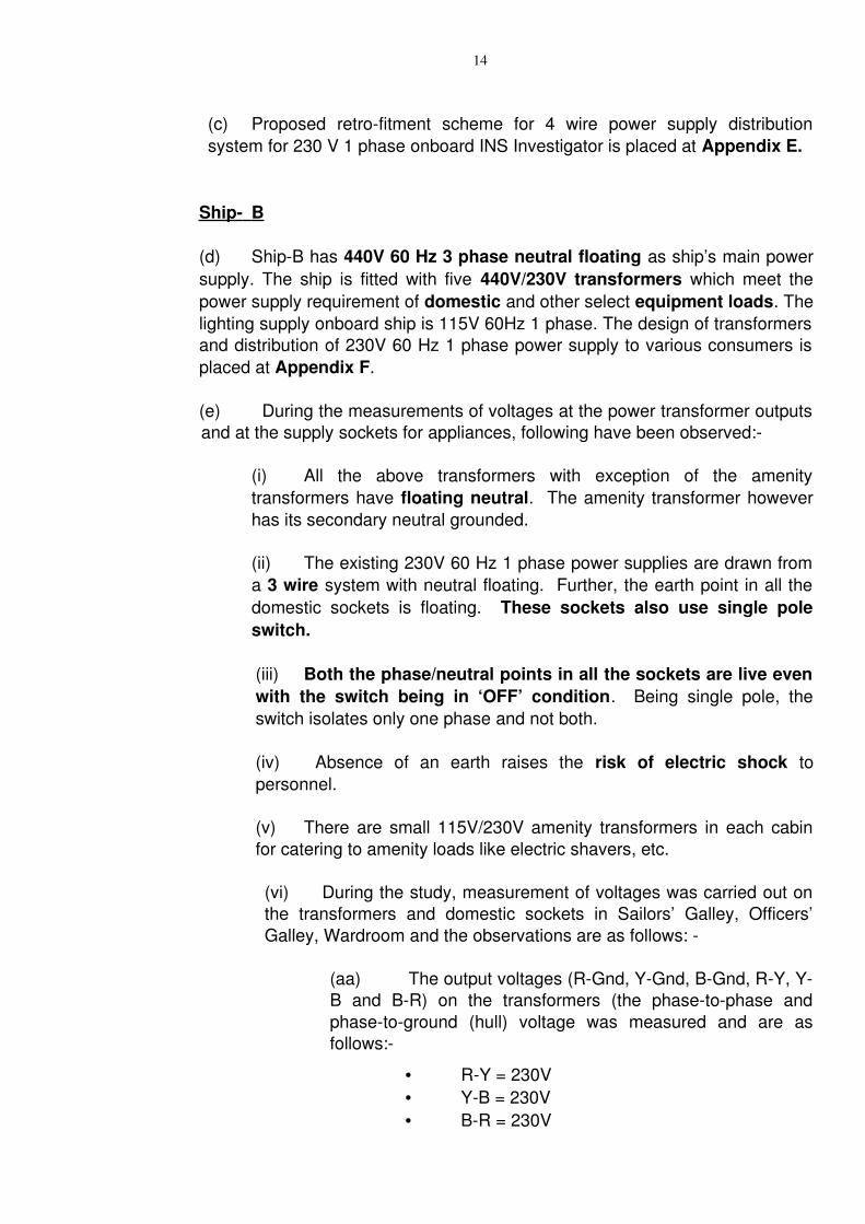
(ab) The voltages at the sockets:
Switch ‘ON’ Switch ‘OFF’P1P2 PGND NGND P1P2 P1GND P2GND
230 115 115 0 0 115
(ac) The sockets fed by amenity transformers are safe as the supplies are taken between phase to earth neutral which is suitably grounded.
(vii) Other than the above transformers, there are two 200 VA 115V/230V transformers for two kitchen equipment in the Officer’s pantry. The supply from these to are similar to the above transformers.
(f) Proposed retrofitment scheme for 4 wire power supply distribution system for 230 V 1 phase onboard INS Godavari is placed at Appendix G.
4.2 Proposed Modification in 230 V Domestic Supplies. Keeping in view the existing arrangement onboard and the requirement of NES 539, a modified domestic distribution system has been worked out. The schematic diagram of the same is placed at Appendix H.
4.3 Summary of the Proposed Domestic Distribution System. In the proposed distribution system, the three wire 415/380 volts to a 230 V 3 Phase, four wire supplies employing a Ү||Ү transformer. The four wire output of the transformer is proposed to be brought to a junction box/power panel which is colocated with the transformer. The power panel comprise of four bus bars, one each for the three phases and one each for the earth. The fourth busbar is earthed to the ship’s hull. Three in number Earth Leakage Circuit Breakers (ELCBs) are employed in each phase and neutral. These breakers will trip in case of detection of earth leakage current thereby providing for automatic interruption of supplies in case of electrocution/earth fault. The single phase circuit to the individual consumers will now comprise of three wires connected to phase, neutral and earth as shown. Unlike the three wire system, where the neutral is live, the neutral in this case is at earth potential
Ph 1
NFloating
Ph 2 (Neutral)
16
as it is grounded to the ship’s hull through the power panel thereby providing added safety. The consumer socket will be a double pole MCB complete with 3 pin socket.
4.4 Incorporation of double Pole MCB. The 230/115 V power supplies to systems such as lighting and equipment, derived from two phases of 3 ph 3 wire (neutral floating) system require the use of double pole MCB complete with 3 pin socket to ensure that both phases at consumer end are ‘dead’ when switch is ‘OFF’.
4.5 Insulation Monitoring from Switchboards. With exception of the Talwar Class of ships, the Main Switchboards of IN Ships are fitted with an off line Insulation Monitoring System. This system facilitates manual checking of insulation of various supply circuits by the switchboard watch keeper. Being manual in nature, the system has some operational limitations. One of the major shortcomings being that the existence of low insulation is known only when the watch keeper carries out a periodic insulation check. Absence of an audio visual alarm for insulation falling below a preset value is the other limitation. Implementation of an online insulation monitoring system is essential for indication of low insulation at the instance of occurrence. Proposal for retrofitment of insulation monitoring device onboard Ship A and Ship B is placed at Appendix J.
17
CHAPTER 5
DOMESTIC SUPPLY SYSTEMS ON NEW CONSTRUCTION SHIPS
5.1 Meetings have been held with the representatives from the Production Directorates to discuss the requirements of NES 539 for for the domestic supplies onboard new construction ships.
5.2 Interaction with DND. During the interaction with DND, it was brought out that the domestic supplies on all the DND ships is 3 wire. It was decided that an immediate corrective action for implementation of a 4 wire system will be initiated onboard all new construction ships. In addition, discussions were held for promulgation of SOTRs for additional components of the 4 wire system. The same are in advance stage of preparation and will be promulgated shortly. Following components have been covered:
(a) 3 wire to 4 wire 415/380 V transformer
(b) Power Supply Distribution Box
(c) Earth Leakage Circuit Breaker (ELCB)
(d) 3 Pin Supply Socket
(e) Miniature Circuit Breaker (MCB)
5.3 Deviation from NES 539 on New Construction Ships. The scheme for the power distribution to the domestic equipment onboard all the new construction ships is a 3 wire system with neutral floating. This does not meet the norms of NES 539 which specifies a 4 wire system. The status and installation of 4 wire system for the domestic supply onboard the DND and DSP ships as corrective action is discussed in the succeeding paragraphs.
5.4 DND Ships.
(a) P17. The existing power supply of 230 V 1 Phase to the domestic supplies is derived from a 415/230 V transformer. The supply available at the consumer socket is from two phases from the transformer. The consumer sockets are nonpatternised switch sockets with a single pole banana switch. Therefore when the switch is in ‘OFF’ condition, one phase is always available at the consumer end and therefore posing risk. At present the design and procurement of cables and MCB panels for all the three ships has been completed. The step down transformers are yet to be procured. Cabling has progressed substantially in the first ship.
18
(b) First Ship of P17. Keeping the above in view, the arrangement proposed for converting the existing 3 wire system to 4 wire systems will be a slight variation of that proposed for existing ships at Appendix H. The following is recommended:
(i) Procurement and installation of 4 wire transformers with three single phase centre tapped/earthed secondary. These will be installed one each in the three fire zones
(ii) Installation of ELCB in the MCBs panels.
(iii) Replacement of the nonpatternised switch sockets having single pole banana switches with MCB sockets consisting of double pole MCB complete with 3 pin socket.
(iv) Two pins of the sockets to be connnected using existing scheme for phase and neutral. The third pin (earth) of the socket will be directly bonded to ships ground to provide earth resistance as per NES.
(v) The variation from the proposed scheme at Appendix H will be that the transformer secondary neutral (which is grounded), will be grounded locally instead of a separate cable running from grounded neutral of 415/230 V transformer to the consumer socket switch. This solution is also considered acceptable in terms of safety.
(c) 2 nd and 3 rd Ship of P17 . The modifications exactly in line with the scheme as proposed in Appendix H is recommende for implementation.
(d) Future Ships – P28, P15 A & ADS. The 4 wire system will be implemented onboard these ships as per the scheme envisaged for existing platforms. Patternised switch sockets will be used.
5.5 DSP Ships. The supply distribution scheme onboard LST(L) class is 230 V 3 phase 3 wire system for the domestic equipment and 230V 1Ph for lighting system. While the 1st ship is due for commissioning in Aug 06, DG trials are in progress in the 2nd ship. 60 % cabling has been completed onboard the 3rd ship. It is proposed that the LST(L) class would be in accordance as per the scheme at Appendix H and retrofitted at later stage. The modification will entail require replacement of the step down transformers which are of ∆||∆ configuration, installation of ELCB in the MCB panel and cable runs.The scheme onboard new FACs would also be in accordance as per the scheme at Appendix H.
19
CHAPTER 6
CONCLUSION AND RECOMMENDATIONS
6.1 Conclusion. The 230 volts power supply distribution circuits onboard warships must conform to two fundamental requirements. The first is to provide earth leakage and earth fault resistant supplies to mission critical systems and the second is to provide safe domestic supply circuit. The first requirement is met by implementing a 3 phase 3 wire system where as implementation of a 3 phase 4 wire system with earthed neutral and fitment of earth leakage protection breakers fulfils the second requirement. The specifications for such circuits are specified in NES 539.
6.2 The study has also highlighted that the existing 230 volts domestic supply circuits onboard indigenous ships do not conform to NES 539. Change over from “Double pole Double throw” switch to “Single pole Single throw” commercial switche s from Project 16 onwards has further compromised onboard electrical safety. Implementation of a 230 volt floating neutral circuit is an acceptable solution for domestic lighting systems, but the galley and other domestic supplies meant for commercial equipment need to have added protection in the form of double pole double throw switches/implementation of 3 phase four wire systems with neutral earthed. This is more so because these supplies feed domestic compartments that are damp and are manned by personnel not trained for handling the operating voltages.
6.3 The study also focued on corrective implementation schemes as retrofitment for existing ships and as abinitio scheme for ships under construction to the extent feasible.
6.4 Recommendations. In the light of above findings, the study recommends following courses of action:
Existing Ships
(a) Retention of three wire neutral floating system for 230 V lighting and equipment employing 230 V three phase supplies. However, the lighting circuits employing “Single pole” switches need to be converted to double pole MCB complete with 3 pin socket. .
(b) 230 volt, 1 phase supplies to galleys, pantries and wet compartments should be modified to a 4 wire system in accordance to the proposed power
20
distribution circuit at Appendix H. Earth leakage circuit breaker protection be also provided in the circuit for added safety. This activity can be undertaken during refits and needs to be undertaken even onboard Russian origin ships.
(c) The 230/115 V power supplies to systems such as lighting and equipment, derived from two phases of 3 ph 3 wire (neutral floating) system should use double pole MCB complete with 3 pin socket to ensure that both phases at consumer end are ‘dead’ when switch is ‘OFF’.
(d) Incorporation of an online insulation monitoring system with audio visual alarm in Main and Distribution Switchboards.
New Construction Ships
(e) 230 volt 1 Phase 3 wire supplies to domestic equipment onboard IAC, P28, P15 A, LST(L), new FACs and 2nd and 3rd ship of P17 is to be modified to a 4 wire system as per proposed modification at Appendix H in compliance with NES Standards.
(f) Though the domestic supply cabling network on the first ship of P17 is in advanced stage of implementation, it is recommended that the domestic supply circuit be redrawn so as to conform to Appendix H to the extent feasible. A close alternative to the same would be as envisaged at Para 5.4 (b) above.
(g) Incorporation of an Online insulation monitoring system, with audio visual alarm, in the Switchboards.
21
Appendix A (Refers to Para 2.1)
STUDY ELECTRIC SHOCK AND PROTECTION CIRCUIT DESIGN
1. Introduction. An electric shock can occur upon contact of a human or animal body with any source of voltage high enough to cause sufficient current flow through the muscles or nerves. The minimum detectable current in humans is thought to be about 1 milliampere. The current may cause tissue damage or heart fibrillation it is sufficiently high. When (and only when) an electric shock is fatal, it is called electrocution.
2. An electric shock is usually painful and can be lethal. Despite the common misconception, the level of voltage is not a direct guide to the level of injury or danger of death. A small shock from static electricity may contain thousands of volts but has very little current behind it due to high internal resistance. Physiological effects and damage are generally determined by current and its duration. Even a low voltage causing a current of extended duration can be fatal. Ohms’s Law directly correlates voltage and current for a given resistance; thus, for a particular path through the body under a particular set of conditions, a higher voltage will produce a higher current flow.
3. Basics of Electric Shock. The following are the factors that determine the severity of the effect electric shock has on a body:
(a) The amount of body resistance to the current flow.
(b) The path the current takes through body.
(c) The length of time the current flows through the body.
4. The body resistance varies greatly in different parts of the body. A value of 1,500 ohms is commonly considered as the resistance between major extremities of an average human body – hand to and or hand to foot. Body resistance varies from person to person and may often be less than 1500 ohms. When the skin is moist, body resistance could be as low as 300 ohms. Also, breaks in skin at the point of contact could reduce skin resistance to nearly zero. Skin resistance is only important when handling voltages of less than 230 V. If one is shocked by more than 230 Volts, the voltage arc will burn through the skin and leave deep third degree burns.
5. Suppose a person accidentally grabs a wire carrying 120 Volts AC Ohm’s law I=E/R can be used to figure how much current would flow through the body. For example:
E=120V ac (the voltage grabbed) R = 1,500 ohms (average body resistance)Then I = 120/1,500 amp i.e. I = 0.080 amp or I = 80 milliamperes
22
(According to the IEEE Std. 80, the maximum safe shock duration can be determined by the formula Seconds = 0.116/(E/R), where R (resistance of person) is assumed to be 1000 ohms).
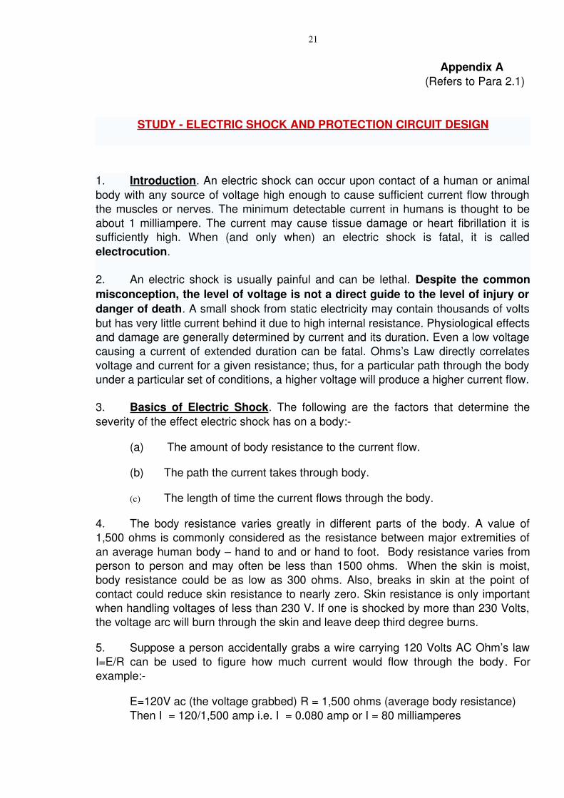
6. Table 1 below depicts the effects of varying amounts of shock current on a normal person.
CURRENT (1 SECOND CONTACT)
PHYSIOLOGICAL EFFECT VOLTAGE REQUIRED TO PRODUCE CURRENT WITH RESISTANCE
100,000 OHMS
1,500 OHMS
1 mA Threshold of feeling, tingling sensation. 100 V 1 V
5 mA Accepted as maximum harmless current 500 V 5 V
1020 mA Beginning of sustained muscular contraction ("Can't let go" current)
1 KV 10 V
100300 mA
Ventricular fibrillation, fatal if continued. Respiratory function continues.
10 KV 100 V
6 A Sustained ventricular contraction followed by normal heart rhythm. (Defibrillation). Temp. respiratory paralysis and possibly burns
50 KV 6 KV
23
Table 1 Effects of varying amounts of shock current
Electrical Shock Effects
7. Psychological. The perception of electric shock can be different depending on the voltage, duration, current, path taken, frequency, etc. Current entering the hand has a threshold of perception of about 5 to 10 milliamperes (mA) for DC and about 1 to 10 mA for AC at 60 Hz. Shock perception declines with increasing frequency, ultimately disappearing at frequencies above 1520 kHz.
8. Burns. Tissue heating due to resistance can cause extensive and deep burns. Highvoltage (> 500 to 1000 V) shocks tend to cause internal burns due to the large energy (which is proportional to the sqaure of the voltage) available from the source. Damage due to current in this case is through tissue heating.
9. Ventricular Fibrillation. A lowvoltage (110 to 230 V), 60Hz AC current traveling through the chest for a fraction of a second may induce ventricular fibrillation at currents as low as 60mA. With DC, 300 to 500 mA is required. If the current has a direct pathway to the heart (e.g., via a cardiac catheter or other electrodes), a much lower current of less than 1 mA, (AC or DC) can cause fibrillation. Fibrillations are usually lethal because all the heart muscle cells move independently. Above 200mA, muscle contractions are so strong that the heart muscles cannot move at all.
10. Neurological Effects. Current can cause interference with nervous control, especially over the heart and lungs. When the current path is through the head, it appears that, with sufficient current, loss of consciousness always occurs swiftly.
Issues Affecting Lethality
11. Other issues affecting lethality are as follows:
(a) Voltage. The comparison between the dangers of alternating current and direct current has been a subject of debate ever since the War of the Currents in the 1880s. DC tends to cause continuous muscular contractions that make the victim hold on to a live conductor, thereby increasing the risk of deep tissue burns. On the other hand, mainsfrequency AC tends to interfere more with the heart's electrical pacemaker, leading to an increased risk of fibrillation. AC at higher frequencies holds a different mixture of hazards, such as RF burns and the possibility of tissue damage with no immediate sensation
24
of pain. Generally, higher frequency AC current tends to run along the skin rather than penetrating and touching vital organs such as the heart. While there will be severe burn damage at higher voltages, it is normally not fatal.
(b) It is believed that human lethality is most common with AC current at 100250 volts, as lower voltages can fail to overcome body resistance while with higher voltages the victim's muscular contractions are often severe enough to cause them to recoil (although there will be considerable burn damage). However, death has occurred from supplies as low as 32 volts. Electrical discharge from lightning tends to travel over the surface of the body causing burns and may cause respiratory problem.
(c) Point of Entry
(i) Macroshock. Current flowing across intact skin and through the body, current travelling from arm to arm, or between an arm and a foot, is likely to traverse the heart, and so is much more dangerous than current travelling between a leg and the ground.
(ii) Microshock. Direct current path to the heart issue.
(d) Current Flow Path. The two most dangerous paths that current can take through the body are from hand to hand and from left hand to either foot. The second path is the MOST DANGEROUS since the current will flow through the heart and other vital organs.
(e) Current Flow Duration. Fibrillations is the shocking of heart into a useless flutter. The longer one is shocked, the more is the chance that the heart will begin to fibrillate. Most people who die from electric shock die from fibrillation. Fibrillation in a normal adult is unlikely if the current in milliamperes is less than 116/t, where “t” is the shock duration in seconds. The longer one is shocked, the less is the current is needed to cause heart fibrillation.
12. Human Electrical Resistance. Research has provided an approximate set of figures for electrical resistance of human contact points under different conditions. These are as follows:
(a) Wire touched by finger: 40,000 to 1,000,000 dry, 4,000 to 15,000Ω Ω Ω wet. Ω
(b) Wire held by hand: 15,000 to 50,000 dry, 3,000 to 5,000 wet. Ω Ω Ω Ω
(c) Metal pliers held by hand: 5,000 to 10,000 dry, 1,000 to 3,000 Ω Ω Ω Ω wet.
(d) Contact with palm of hand: 3,000 to 8,000 dry, 1,000 to 2,000 Ω Ω Ω Ω wet.
25
(e) 1.5 inch metal pipe grasped by one hand: 1,000 to 3,000 dry, 500 Ω Ω Ω to 1,500 wet. Ω
(f) 1.5 inch metal pipe grasped by two hands: 500 to 1,500 k dry, 250 Ω Ω Ω to 750 wet. Ω
(g) Hand immersed in conductive liquid: 200 to 500 . Ω Ω
(h) Foot immersed in conductive liquid: 100 to 300 . Ω Ω
26
Protection against Electric Shock Fundamentals
13. To protect against electric shock from dangerous voltages on metal parts of electrical equipment from a groundfault, it must be quickly removed by opening the circuit’s overcurrent protection device. The time it takes for an overcurrent protection device to open and clear a groundfault, to remove dangerous voltage, is inversely proportional to the magnitude of the fault current. This means that the higher the groundfault current, the less time it will take for the overcurrent device to open and clear the fault. An inverse time circuit breaker or fuse most likely will prevent serious electric shock if the groundfault current is at least six times the rating of the overcurrent protection device. For a 20A circuit, the groundfault current should be at least 120A. As is apparent, the impedance of the fault current path plays a critical and vital role in removing dangerous voltages from metal parts by facilitating the opening of the branchcircuit overcurrent protection device to prevent electric shock or electrocution.
Safe Circuit Design
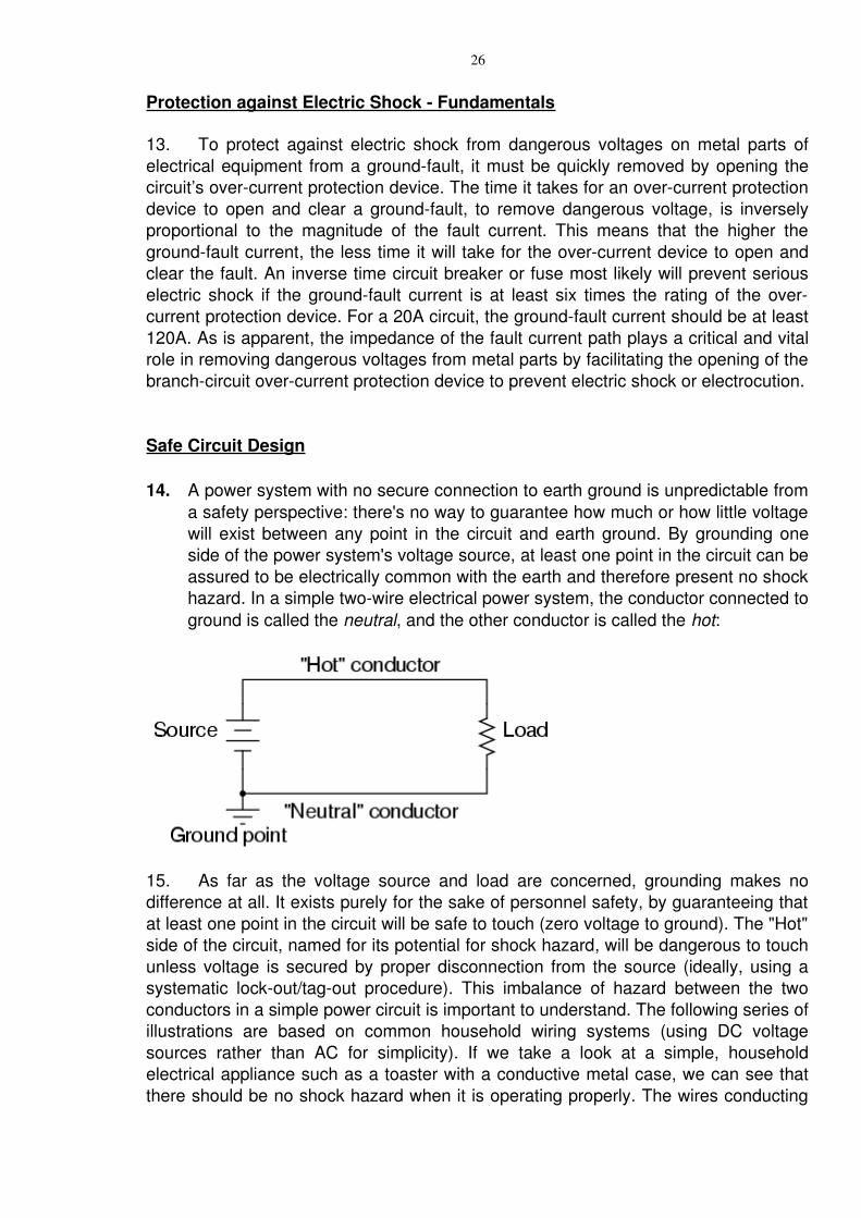
14. A power system with no secure connection to earth ground is unpredictable from a safety perspective: there's no way to guarantee how much or how little voltage will exist between any point in the circuit and earth ground. By grounding one side of the power system's voltage source, at least one point in the circuit can be assured to be electrically common with the earth and therefore present no shock hazard. In a simple twowire electrical power system, the conductor connected to ground is called the neutral, and the other conductor is called the hot:
15. As far as the voltage source and load are concerned, grounding makes no difference at all. It exists purely for the sake of personnel safety, by guaranteeing that at least one point in the circuit will be safe to touch (zero voltage to ground). The "Hot" side of the circuit, named for its potential for shock hazard, will be dangerous to touch unless voltage is secured by proper disconnection from the source (ideally, using a systematic lockout/tagout procedure). This imbalance of hazard between the two conductors in a simple power circuit is important to understand. The following series of illustrations are based on common household wiring systems (using DC voltage sources rather than AC for simplicity). If we take a look at a simple, household electrical appliance such as a toaster with a conductive metal case, we can see that there should be no shock hazard when it is operating properly. The wires conducting
27
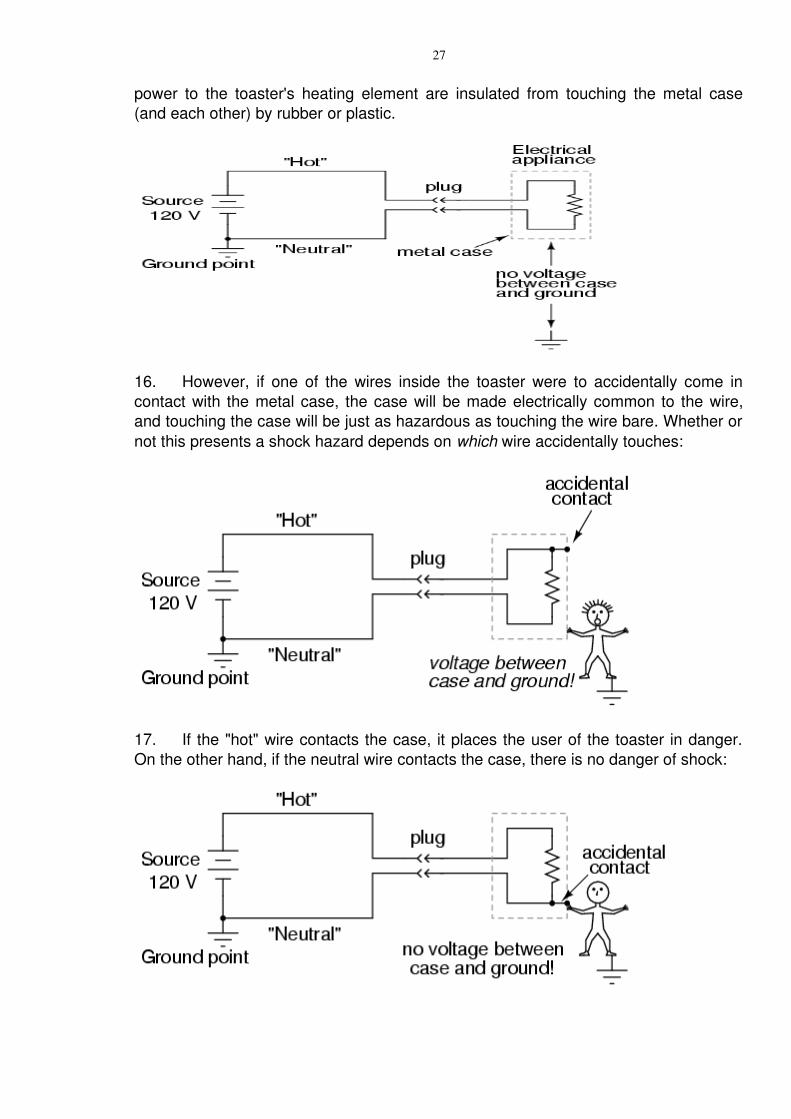
power to the toaster's heating element are insulated from touching the metal case (and each other) by rubber or plastic.
16. However, if one of the wires inside the toaster were to accidentally come in contact with the metal case, the case will be made electrically common to the wire, and touching the case will be just as hazardous as touching the wire bare. Whether or not this presents a shock hazard depends on which wire accidentally touches:
17. If the "hot" wire contacts the case, it places the user of the toaster in danger. On the other hand, if the neutral wire contacts the case, there is no danger of shock:
28
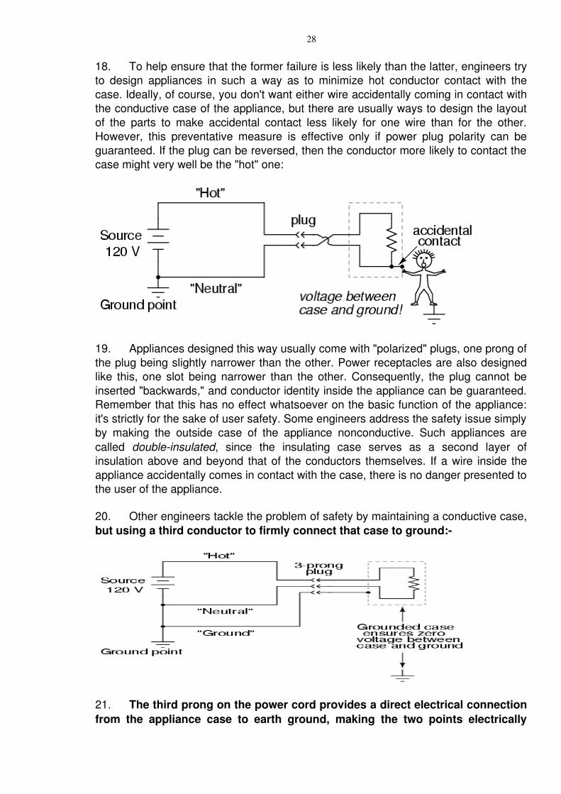
18. To help ensure that the former failure is less likely than the latter, engineers try to design appliances in such a way as to minimize hot conductor contact with the case. Ideally, of course, you don't want either wire accidentally coming in contact with the conductive case of the appliance, but there are usually ways to design the layout of the parts to make accidental contact less likely for one wire than for the other. However, this preventative measure is effective only if power plug polarity can be guaranteed. If the plug can be reversed, then the conductor more likely to contact the case might very well be the "hot" one:
19. Appliances designed this way usually come with "polarized" plugs, one prong of the plug being slightly narrower than the other. Power receptacles are also designed like this, one slot being narrower than the other. Consequently, the plug cannot be inserted "backwards," and conductor identity inside the appliance can be guaranteed. Remember that this has no effect whatsoever on the basic function of the appliance: it's strictly for the sake of user safety. Some engineers address the safety issue simply by making the outside case of the appliance nonconductive. Such appliances are called doubleinsulated, since the insulating case serves as a second layer of insulation above and beyond that of the conductors themselves. If a wire inside the appliance accidentally comes in contact with the case, there is no danger presented to the user of the appliance.
20. Other engineers tackle the problem of safety by maintaining a conductive case, but using a third conductor to firmly connect that case to ground:
21. The third prong on the power cord provides a direct electrical connection from the appliance case to earth ground, making the two points electrically
29
common with each other. If they're electrically common, then there cannot be any voltage dropped between them. At least, that's how it is supposed to work. If the hot conductor accidentally touches the metal appliance case, it will create a direct shortcircuit back to the voltage source through the ground wire, tripping any overcurrent protection devices. The user of the appliance will remain safe.
22. This is why it's so important never to cut the third prong off a power plug when trying to fit it into a twoprong receptacle. If this is done, there will be no grounding of the appliance case to keep the user(s) safe. The appliance will still function properly, but if there is an internal fault bringing the hot wire in contact with the case, the results can be deadly. If a twoprong receptacle must be used, a two to threeprong receptacle adapter can be installed with a grounding wire attached to the receptacle's grounded cover screw. This will maintain the safety of the grounded appliance while plugged in to this type of receptacle. Electrically safe engineering doesn't necessarily end at the load, however. A final safeguard against electrical shock can be arranged on the power supply side of the circuit rather than the appliance itself. This safeguard is called groundfault detection, and it works as shown in the succeeding paragraphs.
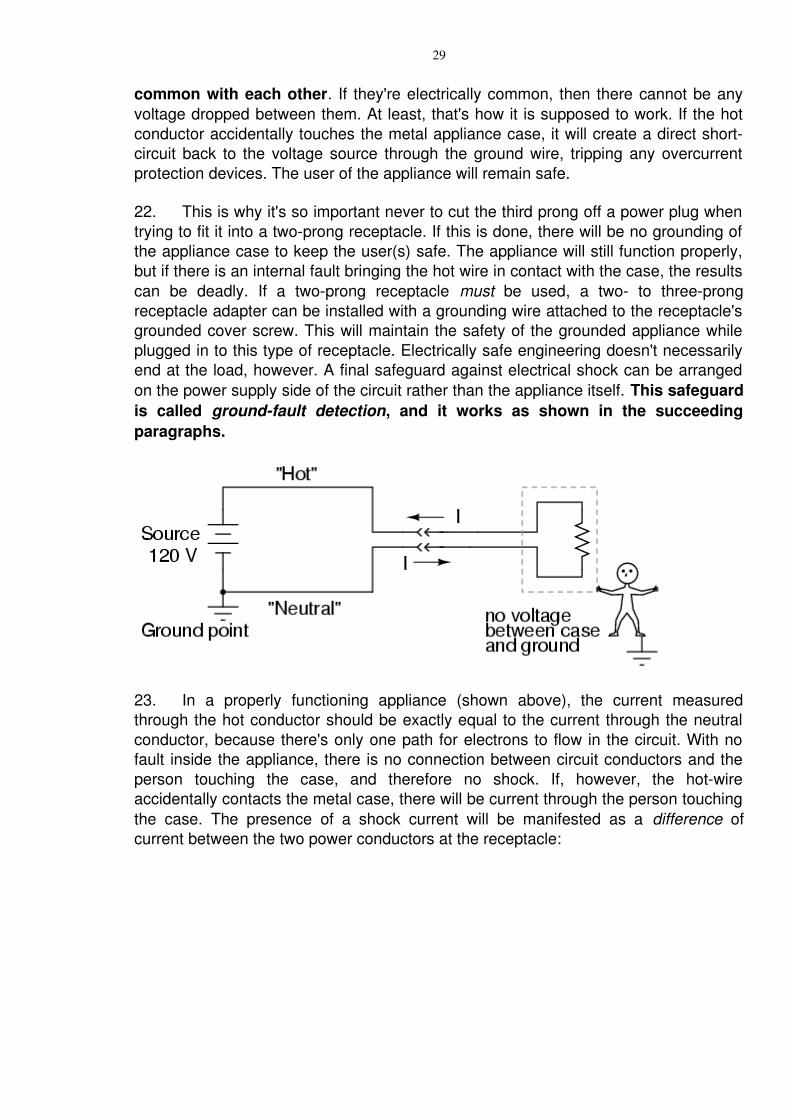
23. In a properly functioning appliance (shown above), the current measured through the hot conductor should be exactly equal to the current through the neutral conductor, because there's only one path for electrons to flow in the circuit. With no fault inside the appliance, there is no connection between circuit conductors and the person touching the case, and therefore no shock. If, however, the hotwire accidentally contacts the metal case, there will be current through the person touching the case. The presence of a shock current will be manifested as a difference of current between the two power conductors at the receptacle:
30
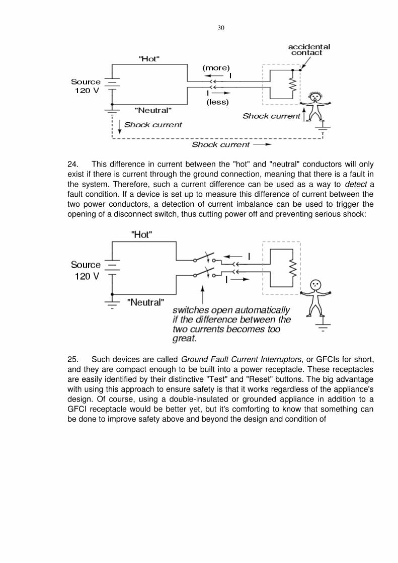
24. This difference in current between the "hot" and "neutral" conductors will only exist if there is current through the ground connection, meaning that there is a fault in the system. Therefore, such a current difference can be used as a way to detect a fault condition. If a device is set up to measure this difference of current between the two power conductors, a detection of current imbalance can be used to trigger the opening of a disconnect switch, thus cutting power off and preventing serious shock:
25. Such devices are called Ground Fault Current Interruptors, or GFCIs for short, and they are compact enough to be built into a power receptacle. These receptacles are easily identified by their distinctive "Test" and "Reset" buttons. The big advantage with using this approach to ensure safety is that it works regardless of the appliance's design. Of course, using a doubleinsulated or grounded appliance in addition to a GFCI receptacle would be better yet, but it's comforting to know that something can be done to improve safety above and beyond the design and condition of
31
Appendix ‘B’ (Refers to Para 2.5)
RELEVANT EXTRACT OF DEF STAN 615 PART 4/1 (ELECTRICAL POWER SYSTEMS BELOW 650 VOLTS PART 4: POWER SUPPLIES
IN HM SHIPS
THE FOLLOWING DEPARTMENT ARE RESPONSIBLE FOR PROVIDING UPDATING INFORMATION IN RESPECT OF THIS STANDARD TO THE DMSCCOMMITTEE ON ELECTRICAL POWER SYSTEMS AND SUPPLIES
HM SURFACE WARSHIPS MOD(PE) DGSHIPS/ 222HM SUBMARINES MOD(PE) DPT/4SHORE SUPPLIES MOD(N) CED
4.1 Scope
This defence standard details all the characteristics of power supplies used in HM warships, submarines and shore base supplies but does not include aircraft servicing & supply characteristics. Terms and Definitions not listed below are contained in Annex ‘B’ (Amendment 1)
4.2 Special Definition Relating to Power Supplies in HM Warship
4.2.1 Normal Supply. The power supply source from winch an equipment normally obtains power.
4.2.2 Alternative supply. A permanent power supply source from which an equipment can obtain power when the normal supply is not available. The alternative supply is derived from a different distribution point from that which provides the normal supply, and the supply cable follows a route different from the normal supply cable route to minimize the risk of losing both normal and alternative supplies through a single damage incident.
Note: Changeover from normal to alternative supply may be made by an automatic switch with a changeover time in range 0.35.0 seconds, or a hand changeover switch.
4.2.3 Emergency Supply. A power supply obtained by rigging a temporary system of emergency cables connected to fixed and portable plugs and sockets; or permanently connected power supply system for providing power to certain radio equipment following failure of the ship’s main power supply.
32
4.2.4 Ship’s Main Power Supply. The 440 V, 60 Hz, 3 phase power supply system or in D.C. ships, the 220 V power supply system.
4.2.5 Unearth Electrical Systems. In ships this refers to a system which is not intentionally connected, either directly or through capacitors, to the metal structure of the ship or (in ships having nonconducting hulls) the earth system, except for radio interference suppression, surge suppression, personnel safety or occasional test purpose.
4.2.6 Limitedbreak Supply. A power supply system .incorporating automatic means for detecting failure of a normal supply and for transferring the equipment load to alternative supply within a specified time delay, according to the requirements of the equipment
4.2.7 Nobreak Supply. As for a Limitedbreak supply but for which the changeover time is zero.
4.2.8 Maintained supply. A nobreak supply in which one of the supplies is derived from a battery and is available only for a specified period.
4.3 Related Specifications (See Annex B, Clause 2) Amendment 1
4.4 Utilisation Equipment Requirements
4.4.1 Introduction. A large proportion of the electrical load of a warship can be taken from the ships main power supply which does not require very close regulation. The switching of these loads will induce large transients and ‘spikes’ which would be determined to equipments of a sensitive nature, if connected to this main supply. This fact is appreciated, and characteristics of a precise power supply for such applications shall be negotiated between the relevant MOD Department and the equipment designer. Wherever possible, however, power shall be taken from the ships main power supplies and the requirements for precise power supplies strictly limited.
The characteristics of the main supply of electrical power available in ships are given in Table A of this Standard.
4.4.2 Order of Preference of Supply Voltage in HM Ships with 60 Hz main Power Supply System.
4.4.2.1 All loads of 5 kVA and above shall he designed for connection to a 440 volts, 60 Hz, 3 Phase, 3 wire system.
4.4.2.2 Where practicable, all machinery and equipment rated at less than 5 kVA shall also be designed for connection to a 440 volts, 60 Hz, 3 Phase system. Where this is either undesirable (eg. for personnel safety) or not practicable, the
33
following shall be the order of preference:
(a) 440 volts, single phase(b) 115 volts, 3 phase(c) 115 volts, single phase
4.4.3 Order of Preference for Frequency. Normally utilisation equipment shall be designed to operate from a 60 Hz supply. Where there are overriding design features demanding a higher frequency, the preferred frequency is 400 Hz.
4.4.4 Phase Rotation. Phase rotation for all 3 phase AC systems will be in the following sequence:
Colour system Red Yellow BlueLetter system A B CNumber system L1 L2 L3
4.4.5 Earthing. All ship supply systems covered by this Standard are unearthed and consumer equipment must not introduce direct or indirect connections between supply lines and earth except for radio interference suppression, surge suppression, personnel safety, or occasional test purposes. Where earth return circuits are essential, for example, in gun firing circuits, isolating transformers must be used.
Note: Designer should note that the potential of individual phase voltages to earth will vary and are not necessarily balanced.
4.4.6 Load unbalance. If a load is composed of a combination of single phase and 3 phase loads, the resulting load unbalance under normal conditions shall not exceed 5%. If this is found impossible to achieve, the arrangements shall be agreed with the relevant MOD Department.
4.4.7 Voltage Spikes. The amplitude and waveform of voltage spikes will vary greatly, dependent on circuit parameters. On 440 Volt system, line to line and line to earth spikes are unlikely to exceed 200 volts in amplitude. For 115 volt systems the corresponding figure is 600 volts.
4.4.7.1 For test purposes, spikes may be simulated by an impulse voltage as defined in BS 923: 1972, clauses 1.2.4 and 4.1.1. This voltage has a front time of 1.2 milliseconds and a time to half value of 50 microseconds. Amplitudes of 2500 volts and 750 volts are recommended test values for 440 volt and 115 volt equipments/
4.4.8 Voltage and Frequency Transients.
Notes:
1. ‘Frequent’ transients may occur about 10 times per hour.
2. ‘Infrequent’ transients may occur about 10 times per 24 hours.
34
3. ‘Rare’ transients will occur less frequently than 10 times per 24 hours but more frequently than once per 2 years, one per week may be taken as typical.
4. ‘Extremely rare over voltage faults’ are unlikely to occur more frequently than once per 2 years.
4.4.9 Waveform Distortion. Care must be taken in design of utilisation equipment to ensure that as far as possible the equipment causes no significant distortion of the voltage waveform of the supply system. Details of equipment that is liable to cause significant waveform distortion shall be passed to relevant MOD Department at an early stage of the design.
Note: To limit radio interference it is desirable that equipment should not reflect on to the mains supply cables interference voltages greater than those specified in BS 1597 – ‘Radio interference suppression on marine installations’.
4.4.10 Pulsed Loads. When it is not possible for equipment designers to avoid pulsed loads, details must be referred to relevant MOD Department.
4.4.11 Non Standard Supplies. Details of utilisation equipment which cannot accept supplies in accordance with Standard or which cannot be designed economically to accept such supplies shall be discussed with the relevant MOD Department at an early stage of the design.
35
Appendix ‘C’ (Refers to Para 2.5)
RELEVANT EXTRACT OF NES 539 (GUIDE TO SHIP DESIGN OF SUPPLY SYSTEM FOR PORTABLE ELECTRICAL EQUIPMENT
6. 2 40 Volts Supplies
0601. Supply facilities at this voltage are only made available for domestic, commercial appliances owned by ships staff eg radios. The most economical method of supplying a large number of sockets is to use a 3 phase transformer and to balance the projected load across the windings. Commercial 13 amp plugs and sockets may be used provided the star point of the transformer secondary is earthed. The normal commercial requirement for single pole switching in the live conductor is then sufficient for commercial equipment to be used safely onboard ships.
0602. Shaving facilities on amenity panels will continue to be derived from the 115 volt system using 115/240V transformers.
System Requirements for New Design Ships (Fig 1)
0603. Voltage at the socket outlet is to be 240v ± 6%. Volt drop in fixed cabling is not to exceed 6 at full load.
0604. Supplies for private equipment sockets are to be obtained from 3 phase 440V/423 V transformers with star connected secondary windings.
0605. The star point is to be bonded to earth (Ship’s hull)
0606. Two sizes of transformer are available – 5 KVA and 2.5 KVA. (It is anticipated that a 5 KVA transformer (or two 2.5 KVA) positioned fore and aft will be sufficient to supply the accommodation areas in a frigate/destroyer.)
0607. The 3 phases and neutral of the transformer are to be taken into a locally mounded power panel which will contain ELCBs and fused line out puts for each phase. The transformer neutral is to be solidly bonded to ship’s hull (earth) at the power panel. The bonding conductor is not be smaller than 2.5 sq mm and the resistance between neutral conductor and hull is to be less than 0.05 ohms.
0608. In the case of the 2.5 KVA transformers each out put from the power panel will feed a group of sockets. The number of sockets on each group is not normally to exceed two (TV) and six (private equipment).
36
0609. In the case of the 2.5 KVA transformer for six group of sockets are to be provided either by paralleling two power panels or by supplying two group of sockets from each out put phase. The number of sockets on each group is not normally to exceed 2 (TV) and 6 (private equipment).
Fig 1. Proposed 240 V System
0610. Splitter boxes are to be used to effect further division of supplies.
0611. Sockets are to be connected between 240 V line and neutral and the method of distribution is two loop from socket to socket using three core 2.5 mm stranded cable –NSN 6145995218288 (Cl Grp 0561). The circuit earth core is to be solidly connected to the neutral/hull bond at the power panel.
0612 Socket outlets to be standard domestic 13 Amp square pin single pole switched type to BS 1363 (see NES 538) mounted individually or integral with the “dry” amenity panel ensuring noninterchangeability with any other system operating at a different voltage. Each socket outlet is to be provided with a label to indicate the maximum power available and the largest fuse permissible in the plug, normally 3 ampere.
0613. Where required an aerial socket is to be provided adjacent the power sockets.0614. Flush and surface mounted sockets are listed in NES 538. The surface mounted sockets are used in unlined accommodation compartments and the flush mounted sockets used in lined compartments only.
Equipment Selection
0619. Associated 240V ac supply equipment is as follows:
a. Transformer
440V 60Hz 3Phase/423V 3 phase and neutral star connected 2.5 KVA or 5KVA.(Star point to be solidly bonded to ships hull) (Currently under development)
b. Power Panel
Current Operated ELCB (One for Group of Sockets
Group of Sockets (2+6)
TRANSFORMERPOWER PANEL
TRANSFORMERPOWER PANEL
37
To accept 240V 60 Hz 3 Phase 4 wire, 5KVA supply and provide 3 No 240V SP & N 7 amp outgoing ways via ELCBs WYLEX type WES 40/4. 30 mA trip.(Currently under development – D171b/480/20/1 DG ships 2062 refers)
c. Switch Socket (see NES 538)13A square pin, SP switched, to BS 1363
Domestic:(1) NSN 5999999331468 (Surface mounted)(2) NSN 5999996387473 (Flush mounted)
Metalclad:
(1) NSN 5999991007160 (Surface mounted)(2) NSN 5999996319970 (Flush mounted)
d. Amenity Panels (See NES 107)
The amenity panel without wash basin (ie ‘dry’ unit) is shown on SDN 003504139.
38
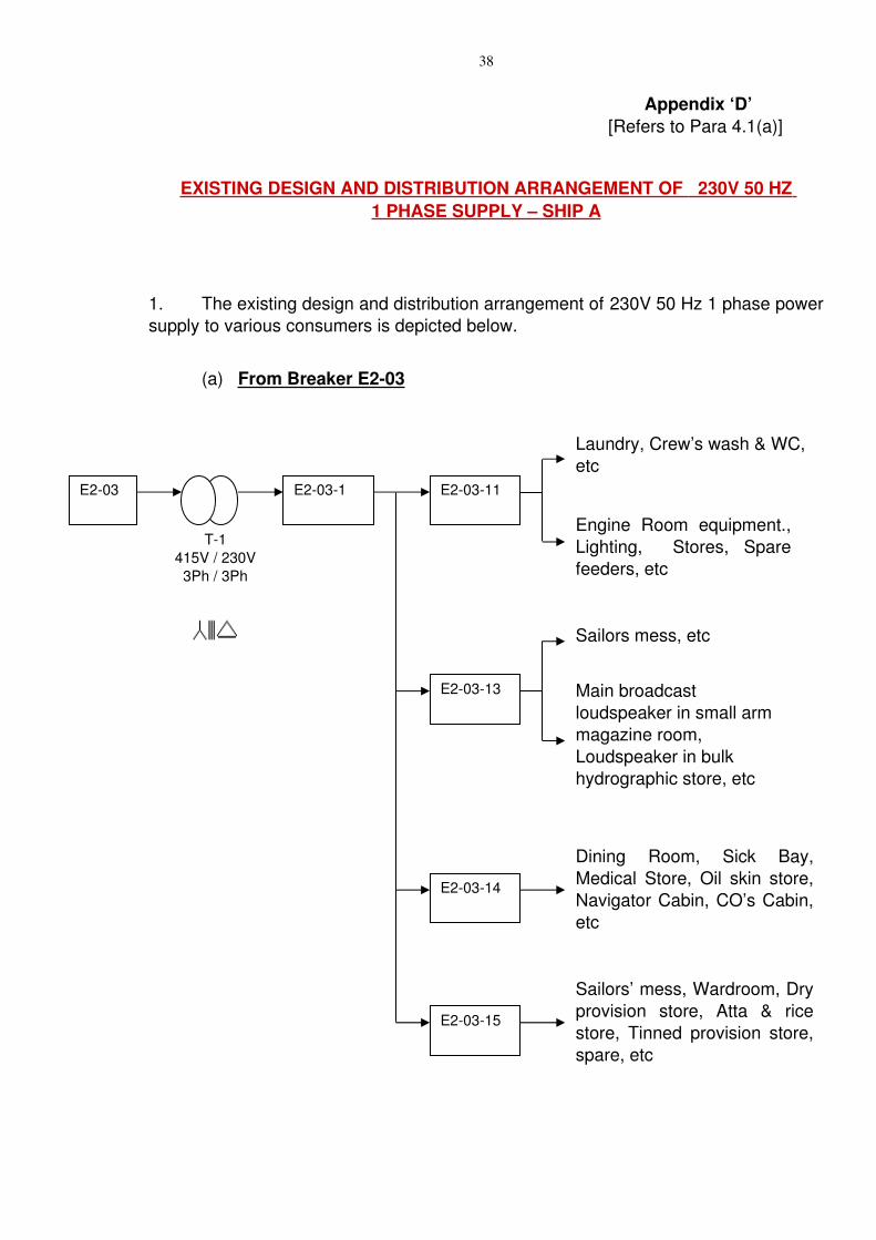
Appendix ‘D’ [Refers to Para 4.1(a)]
EXISTING DESIGN AND DISTRIBUTION ARRANGEMENT OF 230V 50 HZ 1 PHASE SUPPLY – SHIP A
1. The existing design and distribution arrangement of 230V 50 Hz 1 phase power supply to various consumers is depicted below.
(a) From Breaker E203
T1415V / 230V
3Ph / 3Ph
E203 E2031
Laundry, Crew’s wash & WC, etc
Engine Room equipment., Lighting, Stores, Spare feeders, etc
E20311
Sailors mess, etc
Main broadcast loudspeaker in small arm magazine room, Loudspeaker in bulk hydrographic store, etc
E20313
Dining Room, Sick Bay, Medical Store, Oil skin store, Navigator Cabin, CO’s Cabin, etc
E20314
Sailors’ mess, Wardroom, Dry provision store, Atta & rice store, Tinned provision store, spare, etc
E20315
39
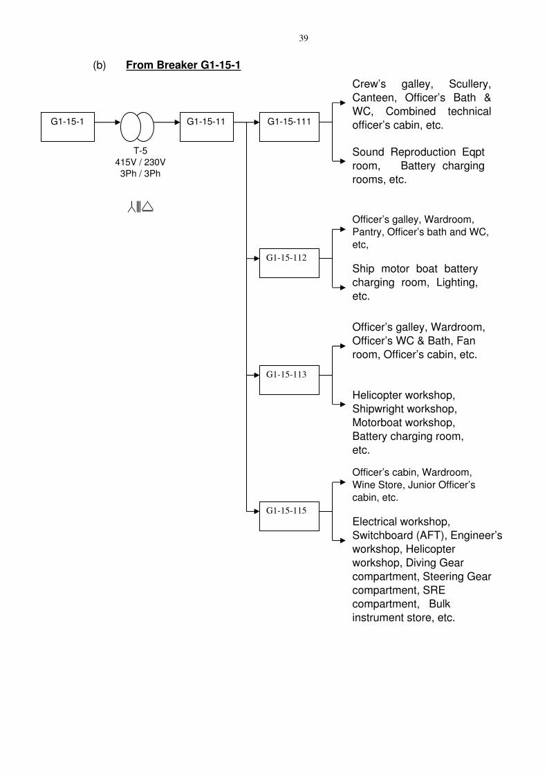
(b) From Breaker G1151
T5415V / 230V
3Ph / 3Ph
G1151 G11511
Crew’s galley, Scullery, Canteen, Officer’s Bath & WC, Combined technical officer’s cabin, etc.
Sound Reproduction Eqpt room, Battery charging rooms, etc.
G115111
Officer’s galley, Wardroom, Pantry, Officer’s bath and WC, etc,
Ship motor boat battery charging room, Lighting, etc.
G115112
G115113
Officer’s galley, Wardroom, Officer’s WC & Bath, Fan room, Officer’s cabin, etc.
Helicopter workshop, Shipwright workshop, Motorboat workshop, Battery charging room, etc.
G115115
Officer’s cabin, Wardroom, Wine Store, Junior Officer’s cabin, etc.
Electrical workshop, Switchboard (AFT), Engineer’s workshop, Helicopter workshop, Diving Gear compartment, Steering Gear compartment, SRE compartment, Bulk instrument store, etc.
40
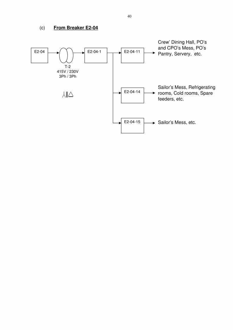
(c) From Breaker E204
T2415V / 230V
3Ph / 3Ph
E204 E2041 E20411
Sailor’s Mess, Refrigerating rooms, Cold rooms, Spare feeders, etc.
E20414
Crew’ Dining Hall, PO’s and CPO’s Mess, PO’s Pantry, Servery, etc.
Sailor’s Mess, etc.E20415
41
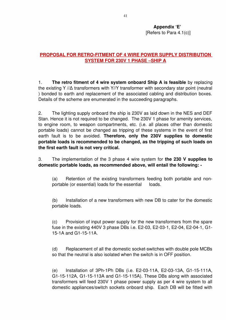
Appendix ‘E’ [Refers to Para 4.1(c)]
PROPOSAL FOR RETROFITMENT OF 4 WIRE POWER SUPPLY DISTRIBUTION SYSTEM FO R 230V 1 PHASE –SHIP A
1. The retro fitment of 4 wire system onboard Ship A is feasible by replacing the existing //Δ transformers with // transformer with secondary star point (neutralΥ Υ Υ) bonded to earth and replacement of the associated cabling and distribution boxes. Details of the scheme are enumerated in the succeeding paragraphs.
2. The lighting supply onboard the ship is 230V as laid down in the NES and DEF Stan. Hence it is not required to be changed. The 230V 1 phase for amenity services, to engine room, to weapon compartments, etc. (i.e. all places other than domestic portable loads) cannot be changed as tripping of these systems in the event of first earth fault is to be avoided. Therefore, only the 230V supplies to domestic portable loads is recommended to be changed, as the tripping of such loads on the first earth fault is not very critical.
3. The implementation of the 3 phase 4 wire system for the 230 V supplies to domestic portable loads, as recommended above, will entail the following:
(a) Retention of the existing transformers feeding both portable and nonportable (or essential) loads for the essential loads.
(b) Installation of a new transformers with new DB to cater for the domestic portable loads.
(c) Provision of input power supply for the new transformers from the spare fuse in the existing 440V 3 phase DBs i.e. E203, E2031, E204, E2041, G1151A and G11511A.
(d) Replacement of all the domestic socketswitches with double pole MCBs so that the neutral is also isolated when the switch is in OFF position.
(e) Installation of 3Ph1Ph DBs (i.e. E20311A, E20313A, G115111A, G115112A, G115113A and G115115A). These DBs along with associated transformers will feed 230V 1 phase power supply as per 4 wire system to all domestic appliances/switch sockets onboard ship. Each DB will be fitted with
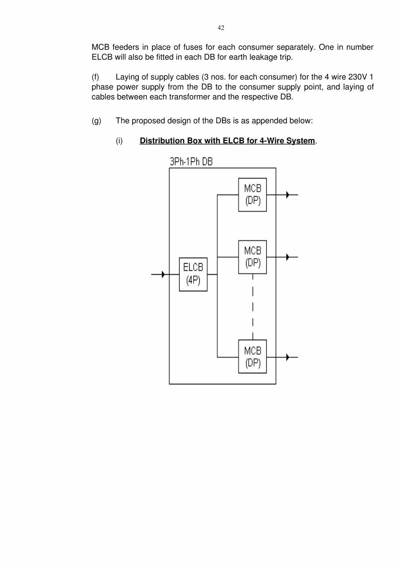
42
MCB feeders in place of fuses for each consumer separately. One in number ELCB will also be fitted in each DB for earth leakage trip.
(f) Laying of supply cables (3 nos. for each consumer) for the 4 wire 230V 1 phase power supply from the DB to the consumer supply point, and laying of cables between each transformer and the respective DB.
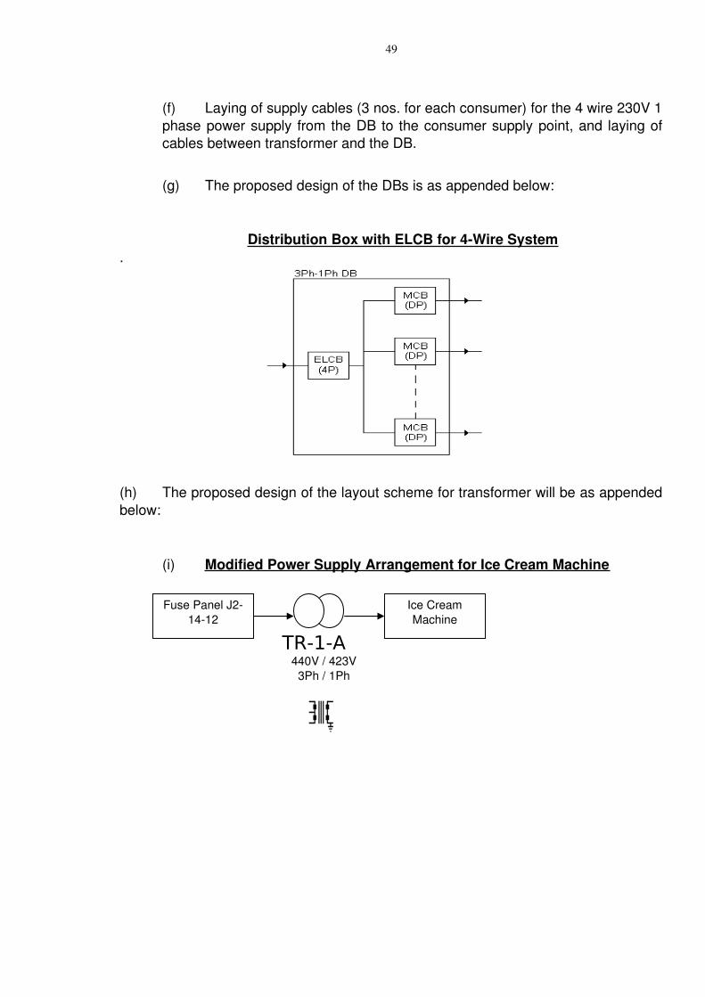
(g) The proposed design of the DBs is as appended below:
(i) Distribution Box with ELCB for 4Wire System.
43
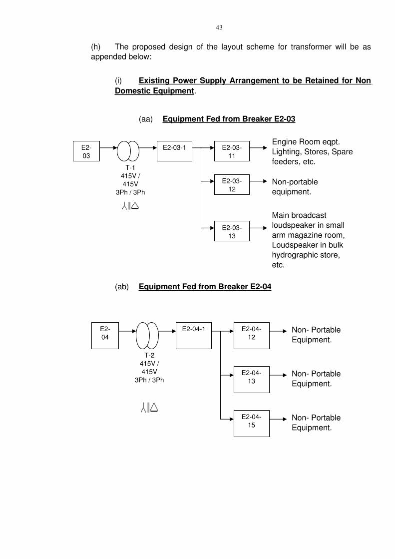
(h) The proposed design of the layout scheme for transformer will be as appended below:
(i) Existing Power Supply Arrangement to be Retained for Non Domestic Equipment.
(aa) Equipment Fed from Breaker E203
(ab) Equipment Fed from Breaker E204
T1415V / 415V
3Ph / 3Ph
E203
E2031Engine Room eqpt. Lighting, Stores, Spare feeders, etc.
E20311
Main broadcast loudspeaker in small arm magazine room, Loudspeaker in bulk hydrographic store, etc.
E20313
Nonportable equipment.
E20312
T2415V / 415V
3Ph / 3Ph
E204
E2041 E20412
E20413
Non Portable Equipment.
E20415
Non Portable Equipment.
Non Portable Equipment.
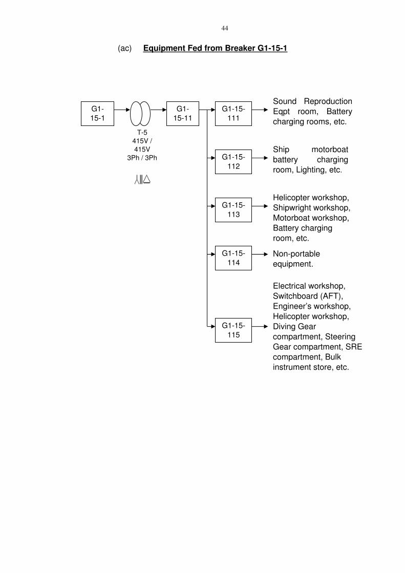
44
(ac) Equipment Fed from Breaker G1151
T5415V / 415V
3Ph / 3Ph
G1151
G11511
Sound Reproduction Eqpt room, Battery charging rooms, etc.
G115111
Ship motorboat battery charging room, Lighting, etc.
G115112
G115113
Helicopter workshop, Shipwright workshop, Motorboat workshop, Battery charging room, etc.
G115115
Electrical workshop, Switchboard (AFT), Engineer’s workshop, Helicopter workshop, Diving Gear compartment, Steering Gear compartment, SRE compartment, Bulk instrument store, etc.
Nonportable equipment.
G115114
45
(ii) 4 Wire 230V 1 Phase Power Supply Distribution Arrangement for Domestic Appliances.
(aa) Equipment fed from Breaker E203
(ab) Equipment fed from Beaker G1151
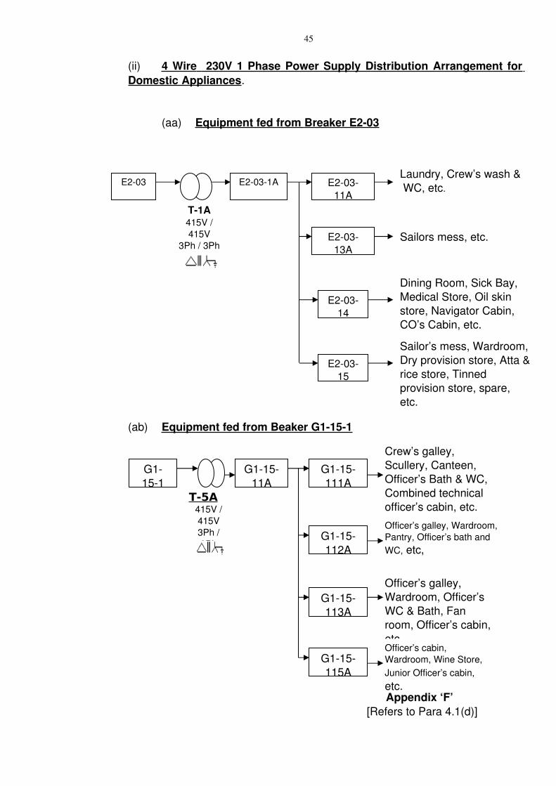
Appendix ‘F’ [Refers to Para 4.1(d)]
T1A415V / 415V
3Ph / 3Ph
E203 E2031ALaundry, Crew’s wash & WC, etc.E203
11A
Sailors mess, etc.E20313A
Dining Room, Sick Bay, Medical Store, Oil skin store, Navigator Cabin, CO’s Cabin, etc.
E20314
Sailor’s mess, Wardroom, Dry provision store, Atta & rice store, Tinned provision store, spare, etc.
E20315
T-5A415V / 415V3Ph / 3Ph
G1151
G11511A
Crew’s galley, Scullery, Canteen, Officer’s Bath & WC, Combined technical officer’s cabin, etc.
G115111A
Officer’s galley, Wardroom, Pantry, Officer’s bath and WC, etc,
G115112A
G115113A
Officer’s galley, Wardroom, Officer’s WC & Bath, Fan room, Officer’s cabin, etc.
G115115A
Officer’s cabin, Wardroom, Wine Store, Junior Officer’s cabin, etc.
46
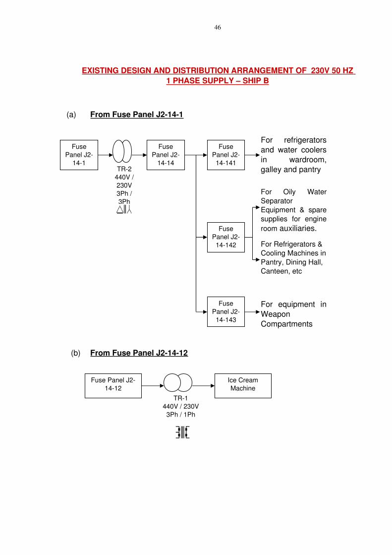
EXISTING DESIGN AND DISTRIBUTION ARRANGEMENT OF 230V 50 HZ 1 PHASE SUPPLY – SHIP B
(a) From Fuse Panel J2141
(b) From Fuse Panel J21412
TR1440V / 230V3Ph / 1Ph
Fuse Panel J21412
Ice Cream Machine
TR2440V / 230V3Ph / 3Ph
Fuse Panel J2
141
Fuse Panel J2
1414
For refrigerators and water coolers in wardroom, galley and pantry
Fuse Panel J2
14141
For Oily Water Separator Equipment & spare supplies for engine room auxiliaries.
For Refrigerators & Cooling Machines in Pantry, Dining Hall, Canteen, etc
For equipment in Weapon Compartments
Fuse Panel J2
14143
Fuse Panel J2
14142
47
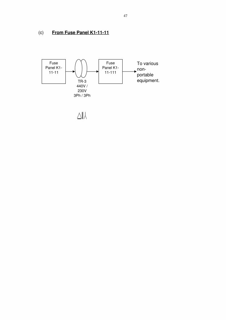
(c) From Fuse Panel K11111
TR3440V / 230V
3Ph / 3Ph
Fuse Panel K1
1111
Fuse Panel K1
11111
To various nonportable equipment.
48
Appendix ‘G’ [Refers to Para 4.1(f)]
PROPOSAL FOR RETROFITMENT OF 4 WIRE POWER SUPPLY DISTRIBUTION SYSTEM FOR 230V 1 PHASE ONBOARD SHIP B
1. The retro fitment of 4wire system is feasible onboard Ship B. It can be undertaken by replacing the existing ∆/Ү transformers with / transformer withΥ Υ secondary star point (neutral) bonded to earth, and the replacement of associated cabling and distribution boxes. Details of the scheme are enumerated in the succeeding paragraphs.
2. The lighting supply onboard the ship is 115V as laid down in the NES and DEF Stan. Hence it is not required to be changed. The 230V 1 phase for amenity services, to engine room, to weapon compartments, etc. (i.e. all places other than domestic portable loads) cannot be changed as tripping of these systems in the event of first earth fault is to be avoided. Therefore, only the 230V supplies to domestic portable loads is recommended to be changed, as the tripping of such loads on the first earth fault is not very critical.
3. The implementation of the 3 phase 4 wire system for the 230 V supplies to domestic portable loads, as recommended above, will entail the following:
(a) Retention of the existing transformer feeding both portable and nonportable (or essential) loads for the essential loads
(b) Installation of a new transformer with a new Distribution Box (DB) to cater for the domestic portable loads. It will also supply power to the two domestic equipment in the Wardroom pantry (which will eliminate the requirement of two existing transformers).
(c) Provision of input power supply to the new transformer from the spare fuse in the existing 440V 3 phase power panel.
(d) Replacement of the entire domestic socketswitches with bipolar switches or double pole MCBs so that the neutral is also isolated when the switch is in OFF position.
(e) Installation of one in number additional DB. (i.e. J21414A) for power supply to the domestic appliances/switch sockets). The DB shall have MCB feeders in place of fuses for each consumer separately. One in number ELCB will also be fitted in the DB for earth leakage trip. Proposed design of the DB along with indicative layout scheme for transformer are appended below:
49
(f) Laying of supply cables (3 nos. for each consumer) for the 4 wire 230V 1 phase power supply from the DB to the consumer supply point, and laying of cables between transformer and the DB.
(g) The proposed design of the DBs is as appended below:
Distribution Box with ELCB for 4Wire System.
(h) The proposed design of the layout scheme for transformer will be as appended below:
(i) Modified Power Supply Arrangement for Ice Cream Machine
TR-1-A440V / 423V
3Ph / 1Ph
Fuse Panel J21412
Ice Cream Machine
50
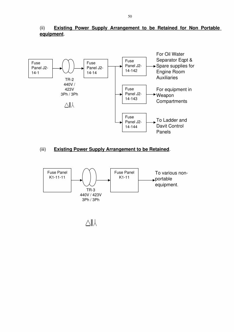
(ii) Existing Power Supply Arrangement to be Retained for Non Portable equipment.
(iii) Existing Power Supply Arrangement to be Retained.
TR3440V / 423V
3Ph / 3Ph
Fuse Panel K11111
Fuse Panel K111
To various nonportable equipment.
TR2440V / 423V
3Ph / 3Ph
Fuse Panel J2141
Fuse Panel J21414
For Oil Water Separator Eqpt & Spare supplies for Engine Room Auxiliaries
For equipment in Weapon Compartments
Fuse Panel J214143
To Ladder and Davit Control Panels
Fuse Panel J214144
Fuse Panel J214142
51
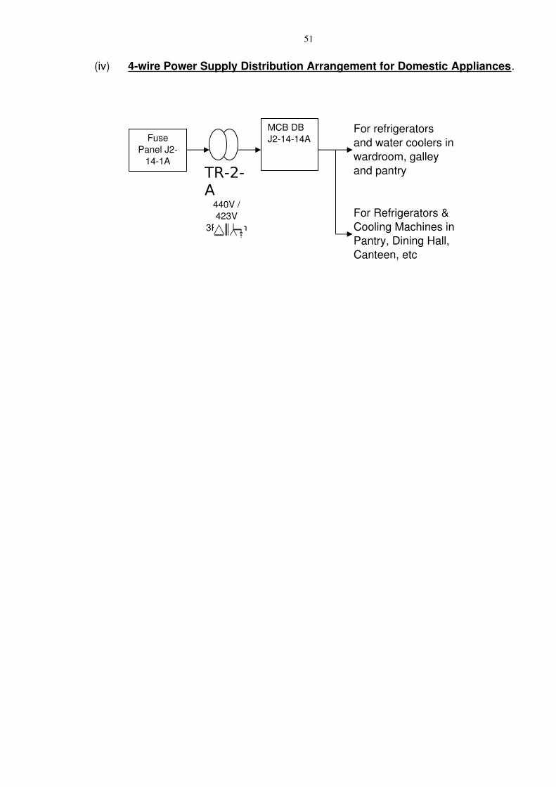
(iv) 4wire Power Supply Distribution Arrangement for Domestic Appliances.
For refrigerators and water coolers in wardroom, galley and pantry
For Refrigerators & Cooling Machines in Pantry, Dining Hall, Canteen, etc
TR-2-A
440V / 423V
3Ph / 3Ph
Fuse Panel J2
141A
MCB DB J21414A

52
Appendix ‘H’
[Refers to Para 4.2]
53
Appendix ‘J’ [Refers to Para 4.5]
PROPOSED ONLINE INSULATION MONITORING SYSTEM ONBOARD SHIP A AND SHIP B
1. Introduction. The Main Switchboard of IN Ships are fitted with an Insulation Measuring Devic. The system has following operational limitations:
(a) The system is not online and provides insulation indication of the selected section.
(b) The system has no provision for audiovisual alarm and judgement is at the discretion of the switchboard watch keeper.
(c) Fault annunciation is not possible and feeders have to be disconnected one by one to locate the fault.
(d) The system is not user friendly as setting of minimum threshold insulation values is not feasible.
(e) Protection against harmonics and other stray DC signal present in the system is not provided.
(f) The system is of vintage design and not supportable.
2. The above design deficiency could be overcome by incorporation of state of the art Online insulation monitoring system on each bus of the Main Power Supply Distribution Switchboard and on Power Transformers (secondary) feeding to lighting & equipment supply. The ship’s galleys are to be provided with audio and visual alarm for low insulation indications reported by any of the Online insulation monitor fitted on ship’s main bus.
3. Proposed Scheme for Ship B. The main bus of each section of the switchboard is to be fitted with Online Insulation Monitoring system IMD (IRDH575).
4. The arrangement for the insulation Monitors is as follows:
54
FWD SWBD
E/R TA Section IMD1(IRDH575)B/R TA Section IMD2 (IRDH575)
AFT SWBD
J1 DA Section IMD3(IRDH575)J2 DA Section IMD4(IRDH575)
5. The insulation monitoring facility can be provided at any of the Switchboard i.e. Forward SWBD or Aft Switchboard. The switchboard with the monitoring facility will be additionally fitted with three meters for indication of insulation recorded by IMDs in other three sections as well. In addition, audiovisual alarms would be provided in switchboards and galleys.
6. The ship will also be provided with two EDS 3060 type Portable insulation monitors for online earth fault detection.
7. Existing system Ship A. The existing Insulation Monitoring System onboard INS Investigator uses an Earth fault meter and three lamps to indicate the health of the insulation. The system has following operational limitations:
(a) The existing system does not provide continuous Online insulation Monitoring. It is only a test device that gets connected by pressing a push button.
(b) Insulation of the manually selected section can only be monitored at a time.
(c) The system sensitivity is low because of the use of analogue meter and lamps.
(d) The system has no provision for audiovisual alarm and judgement is at the discretion of the switchboard watch keeper.
(e) Fault annunciation is not possible and feeders have to be disconnected one by one to locate the fault.
(f) The system is not user friendly as setting of minimum threshold insulation values is not feasible.
(g) Protection against harmonics and other stray DC signal present in the system is not provided.
55
(h) The system is of vintage design and not supportable.
8. Proposed Scheme for Ship B. The main bus of each section of the switchboard is to be fitted with Online Insulation Monitoring system IMD (IRDH575).
9. The arrangement for the insulation Monitors is as follows:
FWD SWBD
E1 DA Section IMD1(IRDH575)E2 DA Section IMD2 (IRDH575)
AFT SWBD
G1 DA Section IMD3(IRDH575)G2 DA Section IMD4(IRDH575)G3 DA Section IMD5 (IRDH575)
10. The insulation monitoring facility can be provided at any of the Switchboard i.e. Forward SWBD or Aft Switchboard. The switchboard with the monitoring facility will be additionally fitted with four meters for indication of insulation recorded by IMDs in other four sections as well. In addition, audio visual alarms would be provided in switchboards and galleys.
11. The ship shall also be provided with two EDS 3060 type Portable insulation monitors for online earth fault detection.
12. ELCB (Earth Leakage Circuit Breaker) be incorporated in the Distribution Board of 4 wire power supply system along with separate MCB for each domestic equipment since incorporation of Online Insulating Monitoring Device is not feasible with 4 wire system.


![Emerging and Future Possible Strategies for Enhancing … · chemical method[35–37] and the electrical method. Among these detection methods, the electrical method is regarded as](https://img.pdfslide.net/doc/110x75/5b8a6fd07f8b9af94b8c25b6/emerging-and-future-possible-strategies-for-enhancing-chemical-method3537.jpg)


![Enhancement the electrical properties of porous silicon ... No. 3 2018 JULY/Vol_11... · Volume 11, No. 3, July 2018 [241-248] Enhancing the Electrical Properties of Porous Silicon](https://img.pdfslide.net/doc/110x75/5e130259c9499d69e11d0b35/enhancement-the-electrical-properties-of-porous-silicon-no-3-2018-julyvol11.jpg)


![Workshop Manual GALANT - Mitsubishifan Fahrzeuge... · 8705:$5781* $0 )$+5=(8* 11111111111157 7dfkrphwhu su†ihq 1111111111111111111111157 ’uhk]dkophvvhu su†ihq 111111111111111111157](https://img.pdfslide.net/doc/110x75/5b76f8cb7f8b9a805c8c1130/workshop-manual-galant-fahrzeuge-87055781-0-58-11111111111157.jpg)


![PEDRO HENRIQUE FAGUNDES DOS SANTOS · 2019-03-20 · 5(6802 2 whpd dsuhvhqwdgr wudwd gh xp hvwxgr vreuh xp ihq{phqr fkdpdgr gh whufhlul]domr (vwh ihq{phqr hvwi fdgd yh] pdlv vhqgr](https://img.pdfslide.net/doc/110x75/5f6e31e92d69d9438342d3d4/pedro-henrique-fagundes-dos-santos-2019-03-20-56802-2-whpd-dsuhvhqwdgr-wudwd.jpg)