Embed Size (px)
Citation preview
A SURVEY OF STANDARDS FOR PRODUCT LIFECYCLE MANAGEMENT OF STRUCTURAL COMPOSITES
Gaurav Ameta Washington State University,
Pullman, WA, 99164
Christopher Brown, Joshua Lubell and Robert Lipman National Institute of Standards and Technology
Gaithersburg, MD, 20899
ABSTRACT Composite materials are widely used in the aerospace, automotive, and sports industries. Designing a composite product requires highly concurrent processes including manufacturing and assembly considerations. This paper examines existing classification schemes for composite materials based on reinforcement and matrix type. Next we review various research, industry, and standards organization efforts to develop computer representation models of composite materials. We then present a survey of specification and verification standards for composite materials, highlighting their gaps and overlaps. Key findings of our analysis are that standard test methods are lacking for particle-reinforced composite materials, and that existing bonding inspection methods and computer-aided design presentation methods for layered composite materials need improvement.
1 INTRODUCTION Composite materials are defined as a combination of two or more individual materials resulting in improved properties than of the individual materials by themselves [1,2]. The materials are usually combined at a macroscopic level and are not soluble in one another. The materials can be reinforcement such as particles or fibers surrounded by a matrix material, or lamina (a single layer) stacked with more laminae to form a laminate. Composite matrix materials may also contain fillers that can reduce weight but are not considered to provide reinforcement. Some composite materials may not have a matrix material and consist of sheets of woven fibers. Composite materials can be non-isotropic, having different physical properties along different directions. Most of the engineered composite materials
are developed to be lightweight and have greater strength in the direction of loading than their isotropic counterparts.
Many composite materials are naturally occurring such as wood while others are manufactured to suit an engineering purpose, for example concrete that is mixed to provide specific properties. Composite materials are commonly used in many products, such as vehicles, airplanes, artificial hips for the medical industry, and sports equipment. According to a 2010 report from the American Composites Manufacturers Association (ACMA), $13.7 billion dollars worth of composite components were traded in the United States [3]. This paper describes the landscape of composite materials, highlighting gaps and overlaps in composite standards throughout the composite product lifecycle.
The next section provides a review of composite product1 design. Section 3 presents various composite material classification schemes, while section 4 discusses different composite material representation standards and modeling efforts to enable an easy transition to analysis models. Section 5 provides a composite material specification and verification standards landscape, followed by issues and opportunities in composite material research. Section 6 offers some concluding remarks.
2 COMPOSITE PRODUCT DESIGN A typical structured design process consists of four stages: requirements study, conceptual design, embodiment design, and detail design [4] followed by manufacturing of the finalized
1 In this paper, the ‘composite product’ term means a composite
composed of raw materials, that could be the final component or assembled with other products to make a final component. The term ‘part’ is not used to avoid the confusion between the raw material ‘parts’ or constituents, the composite ‘parts’ (products), or the assembled final ‘part’ (component).
DISCLAIMER : No approval or endorsement of any commercial product by the National Institute of Standards and Technology is intended or implied.
Proceedings of the ASME 2013 International Design Engineering Technical Conferences and Computers and Information in Engineering Conference
IDETC/CIE 2013 August 4-7, 2013, Portland, Oregon, USA
DETC2013-12655
1 Copyright © 2013 by ASMEThis work is in part a work of the U.S. Government. ASME disclaims all interest in the U.S. Government’s contributions.
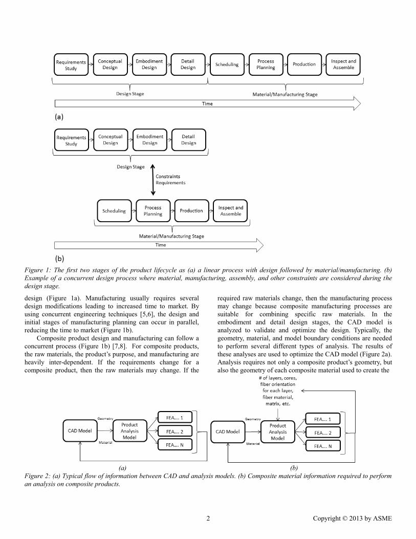
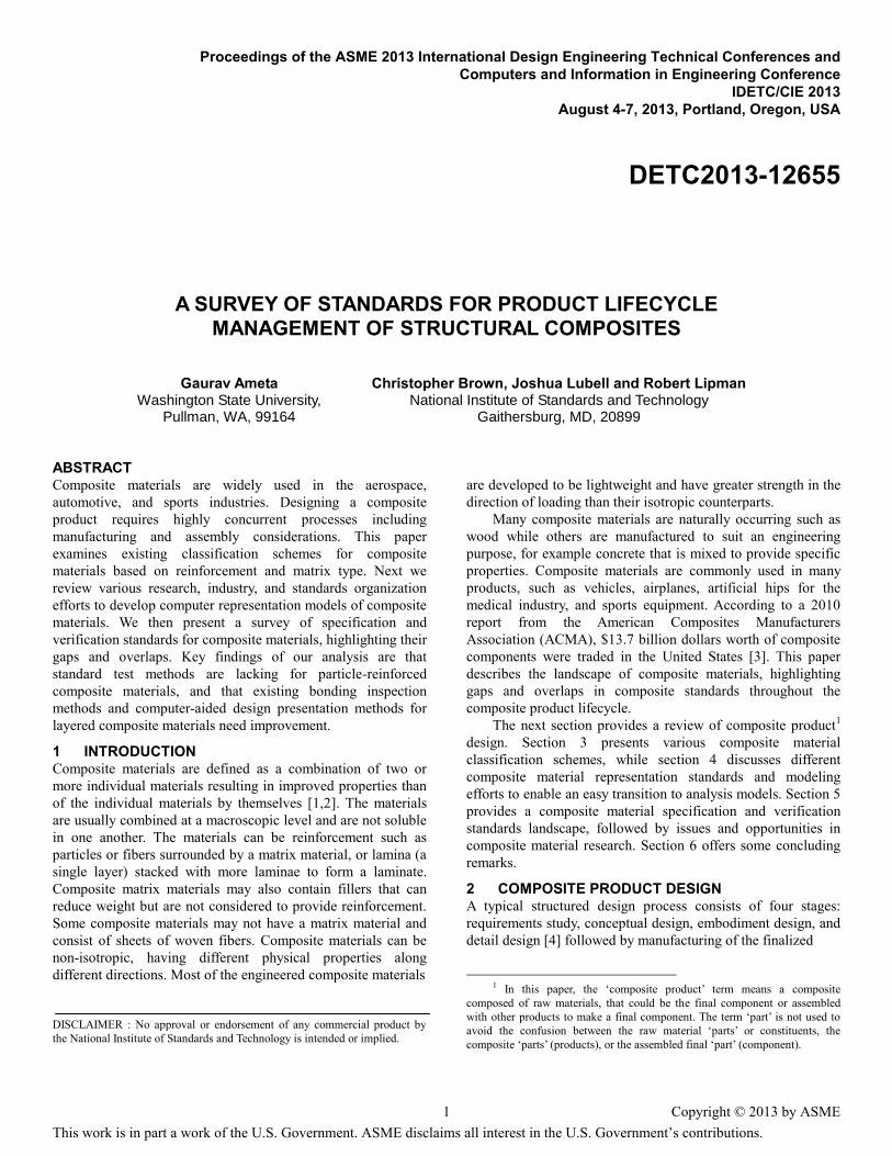
Figure 1: The first two stages of the product lifecycle as (a) a linear process with design followed by material/manufacturing. (b) Example of a concurrent design process where material, manufacturing, assembly, and other constraints are considered during the design stage.
design (Figure 1a). Manufacturing usually requires several design modifications leading to increased time to market. By using concurrent engineering techniques [5,6], the design and initial stages of manufacturing planning can occur in parallel, reducing the time to market (Figure 1b).
Composite product design and manufacturing can follow a concurrent process (Figure 1b) [7,8]. For composite products, the raw materials, the product’s purpose, and manufacturing are heavily inter-dependent. If the requirements change for a composite product, then the raw materials may change. If the
required raw materials change, then the manufacturing process may change because composite manufacturing processes are suitable for combining specific raw materials. In the embodiment and detail design stages, the CAD model is analyzed to validate and optimize the design. Typically, the geometry, material, and model boundary conditions are needed to perform several different types of analysis. The results of these analyses are used to optimize the CAD model (Figure 2a). Analysis requires not only a composite product’s geometry, but also the geometry of each composite material used to create the
(a) (b)
Figure 2: (a) Typical flow of information between CAD and analysis models. (b) Composite material information required to perform an analysis on composite products.
2 Copyright © 2013 by ASME
composite product (Figure 2b). For a fiber-reinforced laminate composite, the material information regarding the number of laminae, fiber orientation in each lamina, fiber material, and matrix has to be separately entered into the product analysis model. Furthermore, the analysis results may be used to modify not only the product geometry and/or material but also all aspects of the constituent laminae, fibers, and cores. The need to support the analysis poses a unique challenge modeling the composite product in CAD. Section 4 will further discuss the modeling efforts and challenges.
3 LANDSCAPE OF COMPOSITE MATERIALS: CLASSIFICATION
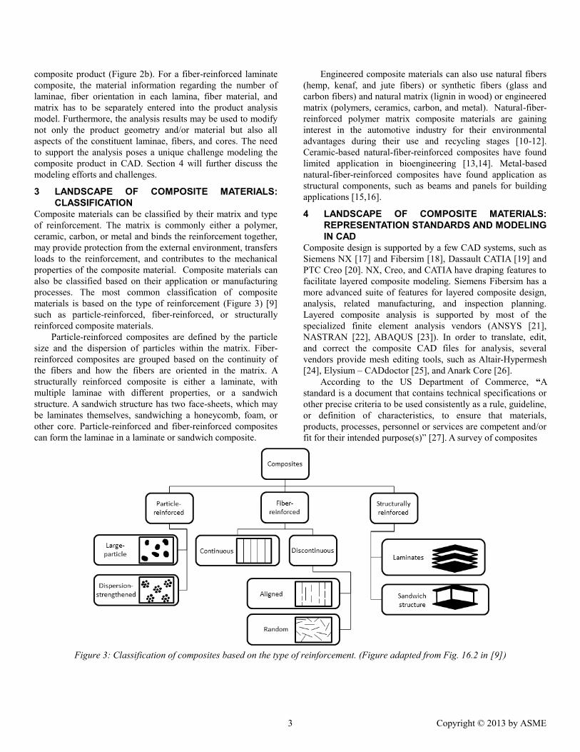
Composite materials can be classified by their matrix and type of reinforcement. The matrix is commonly either a polymer, ceramic, carbon, or metal and binds the reinforcement together, may provide protection from the external environment, transfers loads to the reinforcement, and contributes to the mechanical properties of the composite material. Composite materials can also be classified based on their application or manufacturing processes. The most common classification of composite materials is based on the type of reinforcement (Figure 3) [9] such as particle-reinforced, fiber-reinforced, or structurally reinforced composite materials.
Particle-reinforced composites are defined by the particle size and the dispersion of particles within the matrix. Fiber-reinforced composites are grouped based on the continuity of the fibers and how the fibers are oriented in the matrix. A structurally reinforced composite is either a laminate, with multiple laminae with different properties, or a sandwich structure. A sandwich structure has two face-sheets, which may be laminates themselves, sandwiching a honeycomb, foam, or other core. Particle-reinforced and fiber-reinforced composites can form the laminae in a laminate or sandwich composite.
Engineered composite materials can also use natural fibers (hemp, kenaf, and jute fibers) or synthetic fibers (glass and carbon fibers) and natural matrix (lignin in wood) or engineered matrix (polymers, ceramics, carbon, and metal). Natural-fiber-reinforced polymer matrix composite materials are gaining interest in the automotive industry for their environmental advantages during their use and recycling stages [10-12]. Ceramic-based natural-fiber-reinforced composites have found limited application in bioengineering [13,14]. Metal-based natural-fiber-reinforced composites have found application as structural components, such as beams and panels for building applications [15,16].
4 LANDSCAPE OF COMPOSITE MATERIALS: REPRESENTATION STANDARDS AND MODELING IN CAD
Composite design is supported by a few CAD systems, such as Siemens NX [17] and Fibersim [18], Dassault CATIA [19] and PTC Creo [20]. NX, Creo, and CATIA have draping features to facilitate layered composite modeling. Siemens Fibersim has a more advanced suite of features for layered composite design, analysis, related manufacturing, and inspection planning. Layered composite analysis is supported by most of the specialized finite element analysis vendors (ANSYS [21], NASTRAN [22], ABAQUS [23]). In order to translate, edit, and correct the composite CAD files for analysis, several vendors provide mesh editing tools, such as Altair-Hypermesh [24], Elysium – CADdoctor [25], and Anark Core [26].
According to the US Department of Commerce, “A standard is a document that contains technical specifications or other precise criteria to be used consistently as a rule, guideline, or definition of characteristics, to ensure that materials, products, processes, personnel or services are competent and/or fit for their intended purpose(s)” [27]. A survey of composites
Figure 3: Classification of composites based on the type of reinforcement. (Figure adapted from Fig. 16.2 in [9])
3 Copyright © 2013 by ASME
design and drafting standards is presented in [28]. Section 4.1 discusses representation standards whose data models are applicable to composite materials. Section 4.2 summarizes independent research efforts to model composite materials in CAD. In Section 5, we discuss standards for specification and verification for composite materials.
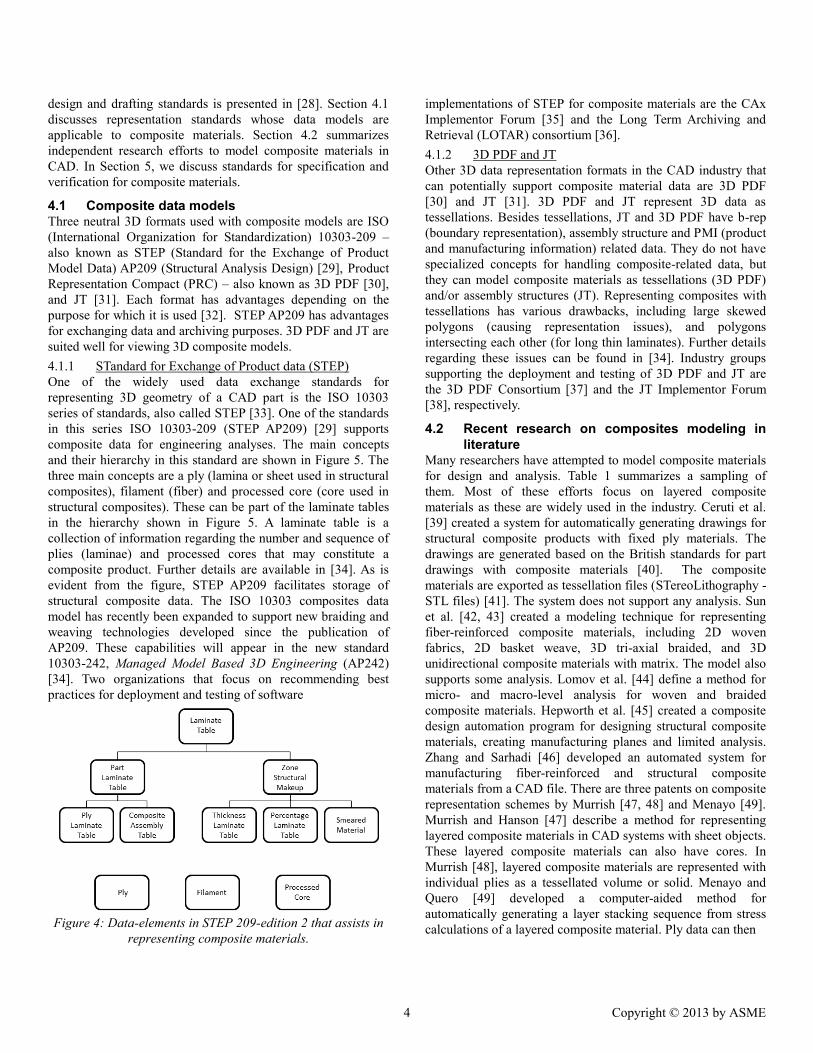
4.1 Composite data models Three neutral 3D formats used with composite models are ISO (International Organization for Standardization) 10303-209 – also known as STEP (Standard for the Exchange of Product Model Data) AP209 (Structural Analysis Design) [29], Product Representation Compact (PRC) – also known as 3D PDF [30], and JT [31]. Each format has advantages depending on the purpose for which it is used [32]. STEP AP209 has advantages for exchanging data and archiving purposes. 3D PDF and JT are suited well for viewing 3D composite models. 4.1.1 STandard for Exchange of Product data (STEP) One of the widely used data exchange standards for representing 3D geometry of a CAD part is the ISO 10303 series of standards, also called STEP [33]. One of the standards in this series ISO 10303-209 (STEP AP209) [29] supports composite data for engineering analyses. The main concepts and their hierarchy in this standard are shown in Figure 5. The three main concepts are a ply (lamina or sheet used in structural composites), filament (fiber) and processed core (core used in structural composites). These can be part of the laminate tables in the hierarchy shown in Figure 5. A laminate table is a collection of information regarding the number and sequence of plies (laminae) and processed cores that may constitute a composite product. Further details are available in [34]. As is evident from the figure, STEP AP209 facilitates storage of structural composite data. The ISO 10303 composites data model has recently been expanded to support new braiding and weaving technologies developed since the publication of AP209. These capabilities will appear in the new standard 10303-242, Managed Model Based 3D Engineering (AP242) [34]. Two organizations that focus on recommending best practices for deployment and testing of software
Figure 4: Data-elements in STEP 209-edition 2 that assists in
representing composite materials.
implementations of STEP for composite materials are the CAx Implementor Forum [35] and the Long Term Archiving and Retrieval (LOTAR) consortium [36]. 4.1.2 3D PDF and JT Other 3D data representation formats in the CAD industry that can potentially support composite material data are 3D PDF [30] and JT [31]. 3D PDF and JT represent 3D data as tessellations. Besides tessellations, JT and 3D PDF have b-rep (boundary representation), assembly structure and PMI (product and manufacturing information) related data. They do not have specialized concepts for handling composite-related data, but they can model composite materials as tessellations (3D PDF) and/or assembly structures (JT). Representing composites with tessellations has various drawbacks, including large skewed polygons (causing representation issues), and polygons intersecting each other (for long thin laminates). Further details regarding these issues can be found in [34]. Industry groups supporting the deployment and testing of 3D PDF and JT are the 3D PDF Consortium [37] and the JT Implementor Forum [38], respectively.
4.2 Recent research on composites modeling in literature
Many researchers have attempted to model composite materials for design and analysis. Table 1 summarizes a sampling of them. Most of these efforts focus on layered composite materials as these are widely used in the industry. Ceruti et al. [39] created a system for automatically generating drawings for structural composite products with fixed ply materials. The drawings are generated based on the British standards for part drawings with composite materials [40]. The composite materials are exported as tessellation files (STereoLithography - STL files) [41]. The system does not support any analysis. Sun et al. [42, 43] created a modeling technique for representing fiber-reinforced composite materials, including 2D woven fabrics, 2D basket weave, 3D tri-axial braided, and 3D unidirectional composite materials with matrix. The model also supports some analysis. Lomov et al. [44] define a method for micro- and macro-level analysis for woven and braided composite materials. Hepworth et al. [45] created a composite design automation program for designing structural composite materials, creating manufacturing planes and limited analysis. Zhang and Sarhadi [46] developed an automated system for manufacturing fiber-reinforced and structural composite materials from a CAD file. There are three patents on composite representation schemes by Murrish [47, 48] and Menayo [49]. Murrish and Hanson [47] describe a method for representing layered composite materials in CAD systems with sheet objects. These layered composite materials can also have cores. In Murrish [48], layered composite materials are represented with individual plies as a tessellated volume or solid. Menayo and Quero [49] developed a computer-aided method for automatically generating a layer stacking sequence from stress calculations of a layered composite material. Ply data can then
4 Copyright © 2013 by ASME
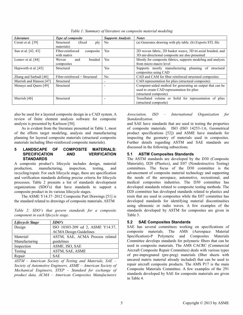
Table 1: Summary of literature on composite material modeling
Literature Type of composite Supports Analysis Notes Ceruti et al. [39] Structural (fixed ply
materials) No (a) Generates drawing with ply table. (b) Exports STL file
Sun et al. [42, 43] Fiber-reinforced composite with matrix
Yes 2D woven fabric, 2D basket weave, 3D tri-axial braided, and 3D uni-directional composite are also presented
Lomov et al. [44] Woven and braided composites
Yes Mostly for composite fabrics, supports modeling and analysis from micro-macro level
Hepworth et al. [45] Structural Yes Supports mostly manufacturing planning of structural composites using CAD
Zhang and Sarhadi [46] Fiber-reinforced + Structural No CAD and CAM for fiber reinforced structural composites Murrish and Hanson [47] Structural - CAD representation for plies (structural composite) Menayo and Quero [49] Structural - Computer-aided method for generating an output that can be
used to create CAD representation for plies (structural composite)
Murrish [48] Structural - Tessellated volume or Solid for representation of plies (structural composite)
also be used for a layered composite design in a CAD system. A review of finite element analysis software for composite analysis is presented by Karlsson [50].
As is evident from the literature presented in Table 1, most of the efforts target modeling, analysis and manufacturing planning for layered composite materials (structural composite materials including fiber-reinforced composite materials).
5 LANDSCAPE OF COMPOSITE MATERIALS: SPECIFICATION AND VERIFICATION STANDARDS
A composite product’s lifecycle includes design, material production, manufacturing, inspection, testing, and recycling/repair. For each lifecycle stage, there are specification and verification standards defining precise criteria for lifecycle processes. Table 2 presents a list of standards development organizations (SDO’s) that have standards to support a composite product in its various lifecycle stages.
The ASME Y14.37–2012 Composite Part Drawings [51] is the standard related to drawings of composite materials. ASTM
Table 2: SDO’s that govern standards for a composite component in each lifecycle stage.
Lifecycle Stage SDO’s Design ISO 10303-209 ed 2, ASME Y14.37,
ACMA Design Guidelines Material/ Manufacturing
ASTM, SAE, ACMA Process related guidelines
Inspection ASME, ISO, SAE Testing ASTM, SAE, ASME Repair SAE ASTM – American Society of Testing and Materials, SAE – Society of Automotive Engineers, ASME – American Society of Mechanical Engineers, STEP – Standard for exchange of product data, ACMA – American Composites Manufacturers
Association, ISO – International Organization for Standardization. and SAE have standards that are used in testing the properties of composite materials. ISO (ISO 14253-1:6, Geometrical product specifications [52]) and ASME have standards for inspecting the geometry of materials used in composites. Further details regarding ASTM and SAE standards are discussed in the following subsections.
5.1 ASTM Composites Standards The ASTM standards are developed by the D30 (Composite Materials), D20 (Plastics), and E07 (Nondestructive Testing) committees. The focus of the D30 committee is the advancement of composite material technology and supporting the needs of the aerospace, automotive, recreational, and medical composites industries. The D30 committee has developed standards related to composite testing methods. The D20 committee has developed standards related to plastics and resin that are used in composites while the E07 committee has developed standards for identifying material discontinuities using ultrasonic or radio waves. A few examples of the standards developed by ASTM for composites are given in Table 3.
5.2 SAE Composites Standards SAE has several committees working on specifications of composite materials. The AMS (Aerospace Material Specification)-P Polymeric and Composites Materials Committee develops standards for polymeric fibers that can be used in composite materials. The AMS CACRC (Commercial Aircraft Composite Repair Committee) deals with various types of pre-impregnated (pre-preg) materials (fiber sheets with uncured matrix material already included) that can be used to repair aircraft composite products. The AMS P17 is the main Composite Materials Committee. A few examples of the 291 standards developed by SAE for composite materials are given in Table 4.
5 Copyright © 2013 by ASME
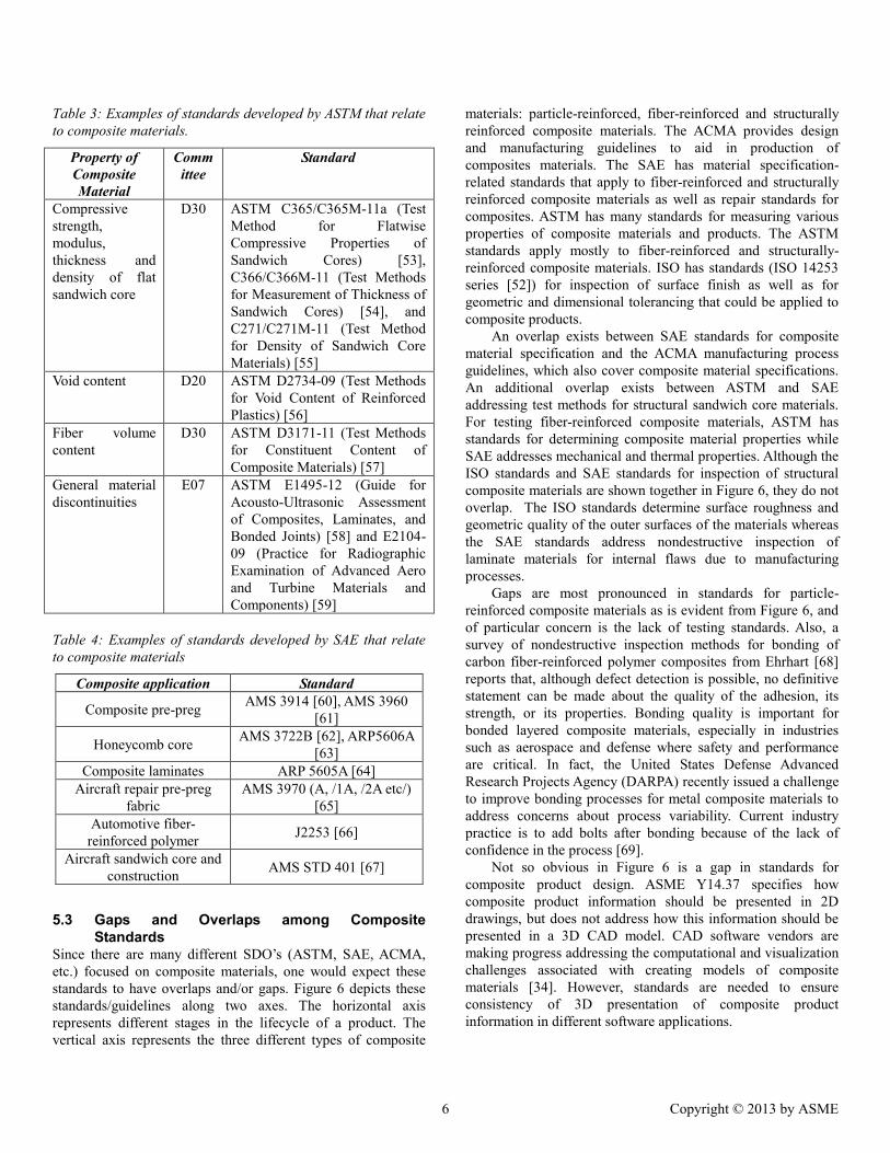
Table 3: Examples of standards developed by ASTM that relate to composite materials.
Property of Composite Material
Committee
Standard
Compressive strength, modulus, thickness and density of flat sandwich core
D30 ASTM C365/C365M-11a (Test Method for Flatwise Compressive Properties of Sandwich Cores) [53], C366/C366M-11 (Test Methods for Measurement of Thickness of Sandwich Cores) [54], and C271/C271M-11 (Test Method for Density of Sandwich Core Materials) [55]
Void content D20 ASTM D2734-09 (Test Methods for Void Content of Reinforced Plastics) [56]
Fiber volume content
D30 ASTM D3171-11 (Test Methods for Constituent Content of Composite Materials) [57]
General material discontinuities
E07 ASTM E1495-12 (Guide for Acousto-Ultrasonic Assessment of Composites, Laminates, and Bonded Joints) [58] and E2104-09 (Practice for Radiographic Examination of Advanced Aero and Turbine Materials and Components) [59]
Table 4: Examples of standards developed by SAE that relate to composite materials
Composite application Standard
Composite pre-preg AMS 3914 [60], AMS 3960 [61]
Honeycomb core AMS 3722B [62], ARP5606A [63]
Composite laminates ARP 5605A [64] Aircraft repair pre-preg
fabric AMS 3970 (A, /1A, /2A etc/)
[65] Automotive fiber-
reinforced polymer J2253 [66]
Aircraft sandwich core and construction AMS STD 401 [67]
5.3 Gaps and Overlaps among Composite Standards
Since there are many different SDO’s (ASTM, SAE, ACMA, etc.) focused on composite materials, one would expect these standards to have overlaps and/or gaps. Figure 6 depicts these standards/guidelines along two axes. The horizontal axis represents different stages in the lifecycle of a product. The vertical axis represents the three different types of composite
materials: particle-reinforced, fiber-reinforced and structurally reinforced composite materials. The ACMA provides design and manufacturing guidelines to aid in production of composites materials. The SAE has material specification-related standards that apply to fiber-reinforced and structurally reinforced composite materials as well as repair standards for composites. ASTM has many standards for measuring various properties of composite materials and products. The ASTM standards apply mostly to fiber-reinforced and structurally-reinforced composite materials. ISO has standards (ISO 14253 series [52]) for inspection of surface finish as well as for geometric and dimensional tolerancing that could be applied to composite products.
An overlap exists between SAE standards for composite material specification and the ACMA manufacturing process guidelines, which also cover composite material specifications. An additional overlap exists between ASTM and SAE addressing test methods for structural sandwich core materials. For testing fiber-reinforced composite materials, ASTM has standards for determining composite material properties while SAE addresses mechanical and thermal properties. Although the ISO standards and SAE standards for inspection of structural composite materials are shown together in Figure 6, they do not overlap. The ISO standards determine surface roughness and geometric quality of the outer surfaces of the materials whereas the SAE standards address nondestructive inspection of laminate materials for internal flaws due to manufacturing processes.
Gaps are most pronounced in standards for particle-reinforced composite materials as is evident from Figure 6, and of particular concern is the lack of testing standards. Also, a survey of nondestructive inspection methods for bonding of carbon fiber-reinforced polymer composites from Ehrhart [68] reports that, although defect detection is possible, no definitive statement can be made about the quality of the adhesion, its strength, or its properties. Bonding quality is important for bonded layered composite materials, especially in industries such as aerospace and defense where safety and performance are critical. In fact, the United States Defense Advanced Research Projects Agency (DARPA) recently issued a challenge to improve bonding processes for metal composite materials to address concerns about process variability. Current industry practice is to add bolts after bonding because of the lack of confidence in the process [69].
Not so obvious in Figure 6 is a gap in standards for composite product design. ASME Y14.37 specifies how composite product information should be presented in 2D drawings, but does not address how this information should be presented in a 3D CAD model. CAD software vendors are making progress addressing the computational and visualization challenges associated with creating models of composite materials [34]. However, standards are needed to ensure consistency of 3D presentation of composite product information in different software applications.
6 Copyright © 2013 by ASME
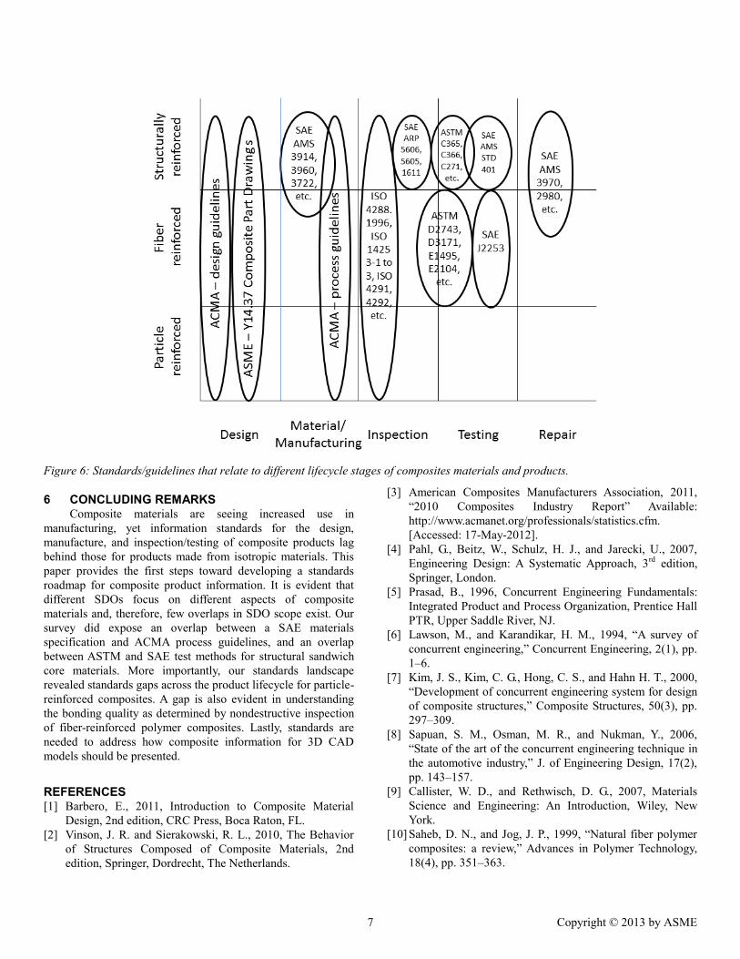
Figure 6: Standards/guidelines that relate to different lifecycle stages of composites materials and products.
6 CONCLUDING REMARKS Composite materials are seeing increased use in
manufacturing, yet information standards for the design, manufacture, and inspection/testing of composite products lag behind those for products made from isotropic materials. This paper provides the first steps toward developing a standards roadmap for composite product information. It is evident that different SDOs focus on different aspects of composite materials and, therefore, few overlaps in SDO scope exist. Our survey did expose an overlap between a SAE materials specification and ACMA process guidelines, and an overlap between ASTM and SAE test methods for structural sandwich core materials. More importantly, our standards landscape revealed standards gaps across the product lifecycle for particle-reinforced composites. A gap is also evident in understanding the bonding quality as determined by nondestructive inspection of fiber-reinforced polymer composites. Lastly, standards are needed to address how composite information for 3D CAD models should be presented.
REFERENCES [1] Barbero, E., 2011, Introduction to Composite Material
Design, 2nd edition, CRC Press, Boca Raton, FL. [2] Vinson, J. R. and Sierakowski, R. L., 2010, The Behavior
of Structures Composed of Composite Materials, 2nd edition, Springer, Dordrecht, The Netherlands.
[3] American Composites Manufacturers Association, 2011, “2010 Composites Industry Report” Available: http://www.acmanet.org/professionals/statistics.cfm. [Accessed: 17-May-2012].
[4] Pahl, G., Beitz, W., Schulz, H. J., and Jarecki, U., 2007, Engineering Design: A Systematic Approach, 3rd edition, Springer, London.
[5] Prasad, B., 1996, Concurrent Engineering Fundamentals: Integrated Product and Process Organization, Prentice Hall PTR, Upper Saddle River, NJ.
[6] Lawson, M., and Karandikar, H. M., 1994, “A survey of concurrent engineering,” Concurrent Engineering, 2(1), pp. 1–6.
[7] Kim, J. S., Kim, C. G., Hong, C. S., and Hahn H. T., 2000, “Development of concurrent engineering system for design of composite structures,” Composite Structures, 50(3), pp. 297–309.
[8] Sapuan, S. M., Osman, M. R., and Nukman, Y., 2006, “State of the art of the concurrent engineering technique in the automotive industry,” J. of Engineering Design, 17(2), pp. 143–157.
[9] Callister, W. D., and Rethwisch, D. G., 2007, Materials Science and Engineering: An Introduction, Wiley, New York.
[10] Saheb, D. N., and Jog, J. P., 1999, “Natural fiber polymer composites: a review,” Advances in Polymer Technology, 18(4), pp. 351–363.
7 Copyright © 2013 by ASME
[11] Holbery, J., and Houston, D., 2006, “Natural-fiber-reinforced polymer composites in automotive applications,” JOM: Journal of the Minerals, Metals and Materials Society, 58(11), pp. 80–86.
[12] Ku, H., Wang, H., Pattarachaiyakoop, N., and Trada, M., 2011, “A review on the tensile properties of natural fiber reinforced polymer composites,” Composites Part B: Engineering, 42(4), pp. 856–873.
[13] Weinmann, M., Kamphowe, T. W., Schuhmacher, J., Müller, K., and Aldinger, F., 2000, “Design of polymeric Si-BCN ceramic precursors for application in fiber-reinforced composite materials,” Chemistry of Materials, 12(8), pp. 2112–2122.
[14] Greil, P., Lifka, T., and Kaindl, A., 1998, “Biomorphic cellular silicon carbide ceramics from wood: I. Processing and microstructure,” Journal of the European Ceramic Society, 18(14), pp. 1961–1973.
[15] Burgueño, R., Quagliata, M. J., Mohanty, A. K., Mehta, G., Drzal, L. T., and Misra, M., 2004, “Load-bearing natural fiber composite cellular beams and panels,” Composites Part A: Applied Science and Manufacturing, 35(6), pp. 645–656.
[16] Dweib, M. A., Hu, B., O’Donnell, A., Shenton, H. W., and Wool, R. P., 2004, “All natural composite sandwich beams for structural applications,” Composite Structures, 63(2), pp. 147–157.
[17] “NX: Siemens PLM Software”, Available: http://www.plm.automation.siemens.com/en_us/products/nx/. [Accessed: 29-Oct-2012].
[18] “Fibersim: Siemens PLM Software”, Available: http://www.plm.automation.siemens.com/en_us/products/fibersim/. [Accessed: 08-Jan-2013].
[19] “3D CAD design software CATIA - Dassault Systèmes”, Available: http://www.3ds.com/products/catia/. [Accessed: 29-Oct-2012].
[20] “3D CAD | 3D Product Design| Creo Parametric | PTC”, Available: http://www.ptc.com/product/creo/parametric. [Accessed: 29-Oct-2012].
[21] “ANSYS - Simulation Driven Product Development”, Available: http://www.ansys.com/. [Accessed: 29-Oct-2012].
[22] “MSC Nastran for FEA”, Available: http://www.mscsoftware.com/products/cae-tools/msc-nastran.aspx. [Accessed: 29-Oct-2012].
[23] “Abaqus Overview - Dassault Systèmes”, Available: http://www.3ds.com/products/simulia/portfolio/abaqus/overview/. [Accessed: 29-Oct-2012].
[24] “Finite Element Pre Processor - Altair HyperMesh”, Available: http://www.altairhyperworks.com/Product,7,HyperMesh.aspx?AspxAutoDetectCookieSupport=1. [Accessed: 29-Oct-2012].
[25] Elysium Inc. - Products: CADdoctor”, Available: http://www.elysiuminc.com/Products/caddoctor.asp. [Accessed: 29-Oct-2012].
[26] “Advanced 3D Solutions - Anark Corporation | Unleash the Model Based Enterprise”, Available: http://www.anark.com/. [Accessed: 29-Oct-2012].
[27] [“NIST Global Standards Information Standards”, Available: http://gsi.nist.gov/global/index.cfm/L1-5/L2-44. [Accessed: 17-Oct-2012].
[28] Aronsson, A., 2005, Design, Modeling and Drafting of Composite Structures, Masters Thesis, Luleå University of Technology, http://epubl.ltu.se/1402-1617/2005/060/LTU-EX-05060-SE.pdf.
[29] ISO 10303-209:2001 - Industrial automation systems and integration -- Product data representation and exchange -- Part 209: Application protocol: Composite and metallic structural analysis and related design, International Organization for Standardization (ISO), Geneva, Switzerland, 2001.
[30] ISO/DIS 14739-1.3 - Document management - 3D use of Product Representation Compact (PRC) format - Part 1: PRC 10001, International Organization for Standardization (ISO), Geneva, Switzerland, 2013-03-07.
[31] ISO 14306:2012 - Industrial automation systems and integration - JT file format specification for 3D visualization, International Organization for Standardization (ISO), Geneva, Switzerland, 2012.
[32] PROSTEP, 2011, White Paper: 3D Formats in the Field of Engineering - a Comparison, ed. Arnulf Fröhlich, PROSTEP AG, Darmstadt, Germany.
[33] 2006, STEP Application Handbook, SCRA, North Charleston, SC.
[34] Hunten, K. A., Feeney, A. B., and Srinivasan, V., “Recent Advances in Sharing Standardized Composite Structure Design and Manufacturing Information,” Computer Aided Design, in review.
[35] “CAx Implementor Forum”, Available: http://www.cax-if.org/. [Accessed: 07-Nov-2012].
[36] “LOTAR: Composites”, Available: http://lotar-international.org/index.php?id=63. [Accessed: 07-Nov-2012].
[37] "3DPDF - Transforming Visual Communication", 3D PDF Consortium, Available: http://3dpdfconsortium.org/. [Accessed: 19-Mar-2013].
[38] "JT Implemntor Forum", ProStep iVip, Available: http://www.prostep.org/en/alte-seiten/project-groups/jt-implementor-forum.html. [Accessed: 19-Mar-2013].
[39] Ceruti, A., Francia, D., Liverani, A., Caligiana, G., 2011, A CAD toolbox for Composite Materials Modeling and Drawing, Proceedings of the IMProVe, Venice, Italy.
[40] BS EN 4408-1:2005 - Aerospace series. Technical drawings. Representation of parts made of composite materials. General rules – BSI British Standards, 2005.
[41] Leong, K. F., Chua, C. K., and Ng, Y. M., 1996, “A study of stereolithography file errors and repair. Part 1. Generic solution,” The International Journal of Advanced Manufacturing Technology, 12(6), pp. 407–414.
8 Copyright © 2013 by ASME
[42] Sun, W., 2000, “Multi-volume CAD modeling for heterogeneous object design and fabrication,” Journal of Computer Science and Technology, 15(1), pp. 27–36.
[43] Sun, W., Lin, F., and Hu, X., 2001, “Computer-aided design and modeling of composite unit cells,” Composites Science and Technology, 61(2), pp. 289–299.
[44] Lomov, S. V., Ivanov, D. S., Verpoest, I., Zako, M., Kurashiki, T., Nakai, H., and Hirosawa, S., 2007, “Meso-FE modeling of textile composites: Road map, data flow and algorithms,” Composites Science and Technology, 67(9), pp. 1870–1891.
[45] Hepworth, A. I., Jensen, C. G., and Roach, J. T., 2009, “A CAD Independent Approach to Automate Laminate Composite Design and Analysis,” Computer-Aided Design & Applications, 6(2), pp. 147-156.
[46] Zhang, Z., and Sarhadi, M., 1996, “An integrated CAD/CAM system for automated composite manufacture,” Journal of Materials Processing Technology, 61(1–2), pp. 104–109.
[47] Murrish, R. E., and Hanson, C. T., “Alternate ply representation for composite design and manufacturing”, U.S. Patent 7099725, August 29, 2006.
[48] Murrish, R. E., “Methods and systems for explicit representation of composite structures, U.S. Patent 7809531, October 5, 2010.
[49] Menayo, G. M., and Quero, A. B., Computer-aided method of obtaining a ply model of a composite component, U.S. Patent Application 20070244590, October 18, 2007.
[50] Karlsson, H., 2005, “Evaluation of FE-Software for Mechanical Analysis of Composite Materials” Available:http://pure.ltu.se/portal/files/30953594/LTU-EX-05058-SE.pdf.
[51] ASTM Y14.37-2012, Composite part drawings engineering drawing and related documentation practices, American Society of Mechanical Engineers (ASME), NY, NY, 2012.
[52] ISO 14253-2:2011 - Geometrical product specifications (GPS) - Inspection by measurement of workpieces and measuring equipment - Part 2: Guidance for the estimation of uncertainty in GPS measurement, in calibration of measuring equipment and in product verification”, International Organization for Standardization (ISO), Geneva, Switzerland, 2011.
[53] ASTM C365/C365M-11a:D30 Committee, Test Method for Flatwise Compressive Properties of Sandwich Cores, ASTM International, West Conshohocken, PA, 2011.
[54] ASTM C366/C366M-11:D30 Committee, Test Methods for Measurement of Thickness of Sandwich Cores, ASTM International, West Conshohocken, PA, 2011.
[55] ASTM C271/C271M-11:D30 Committee, Test Method for Density of Sandwich Core Materials, ASTM International, West Conshohocken, PA, 2011.
[56] ASTM D2743-09:D20 Committee, Test Methods for Void Content of Reinforced Plastics, ASTM International, West Conshohocken, PA, 2009.
[57] ASTM D3171-11:D30 Committee, Test Methods for Constituent Content of Composite Materials, ASTM International, West Conshohocken, PA, 2011.
[58] ASTM E1495.E1495M-12:E07 Committee, Guide for Acousto-Ultrasonic Assessment of Composites, Laminates, and Bonded Joints, ASTM International, West Conshohocken, PA, 2012.
[59] ASTM E2104-09:E07 Committee, Practice for Radiographic Examination of Advanced Aero and Turbine Materials and Components, ASTM International, West Conshohocken, PA, 2009.
[60] SAE AMS3914:P17 committee, Advanced Composites Prepreg - Nominal 250 °F Cure – 12K Tow Carbon Fiber and Epoxy Resin, Plain Weave Fabric, SAE International, Warrendale, PA, 2012.
[61] SAE AMS3960:P17 committee, Advanced Composites Prepreg - Nominal 250 °F Cure - Carbon Fiber and Epoxy Resin, Unidirectional Tape, SAE International, Warrendale, PA, 2011.
[62] SAE AMS3722:P committee, Paper Honeycomb, 125 lb (55 kg) Paper, SAE International, Warrendale, PA, 2012.
[63] SAE ARP5606:CCARC committee, Composite Honeycomb NDI Reference Standards, SAE International, Warrendale, PA, 2011.
[64] SAE ARP5605:CACRC Committee, Solid Composite Laminate NDI Reference Standards, SAE International, Warrendale, PA, 2011.
[65] SAE AMS 3970:CACRC Committee, Carbon Fiber Fabric Repair Prepreg, 120 °C (250 °F) Vacuum Curing, SAE International, Warrendale, PA, 2011.
[66] SAE J2253: Plastics Committee, 1995, Test Procedures for Automotive Structural Composite Materials, SAE International, Warrendale, PA, 1995.
[67] SAE AMSSTD401: P 17 Committee, Sandwich Constructions and Core Materials; General Test Methods, SAE International, Warrendale, PA, 1999.
[68] Ehrhart, B., Valeske, B., Muller C. E., and Bockenheimer, C., 2010, “Methods for the Quality Assessment of Adhesive Bonded CFRP Structures-A Resumé,” Proceedings of Int. Symposium on NDT in Aerospace, Hamburg, Germany, pp. 22–24.
[69] Maher, M., 2012, “Open Manufacturing,” Briefing prepared for: SAMPE Direct Part Manufacturing Workshop, November 13.
9 Copyright © 2013 by ASME