Embed Size (px)
Citation preview
A VIBRATION ISOLATION SYSTEM FOR USE IN A LARGE THERMAL VACUUM TEST FACILITY
Donald Hershfeld and Julie Van Campen
ManTech International Corporation, Aerospace Application Technology Center Goddard Space Flight Center
ABSTRACT
A thermal vacuum payload platfom that is isolated f?om background vibration is required to support the development of future instruments for Hubble Space Telescope (HST) and the Next Generation Space Telescope (NGST) at the Goddard Space Flight Center (GSFC). Because of the size and weight of tie thermaVvacuum facility in whch the instruments are tested, it is not practical to isolate the entire faciliy externally. Therefore, a vibration isolation system has been designed and fabricated to be installed inside the chamber.
The isolation system provides a payload interface of 3.05 m (1 0 feet) in diameter and is capable of supporting a maximum payload weight of 4536 kg (1 0,000 Ibs). A counterweight system has been included to insure stability of payloads having high centers of gravity. The vibration isolation system poses a potential problem in that leakage into the chamber could compromise the ability to maintain vacuum Strict specifications were imposed on the isolation system design to minimize leakage.
Vibration measurements, obtained inside the chamber, prior to installing the vibration isolation system! indicated levels in all axes of approximately 1 milli-g at about 20 Hz. The vibration is012tim system wzs designed to provide a minimum attenuation of 40 dB to these levels.
This paper describes the design and testing of this unique vibration isolation system Problems with leakage and corrective methods are presented. Isolation performance results are also presented.
INTRODUCTION
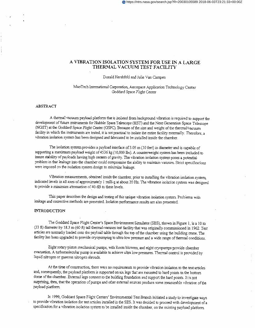
The Goddard Space Flight Center's Space Environment Simulator (SES), shown inFi,we 1, is a 10 m (33 ft) diameter by 18.3 m (60 ft) tall thermal-vacuum test facility that was originally commissioned in 1962. Test ahcles =e nomdly loaded onto the pqload table ttzoug! thc top of the ckaiibei using the brrildiag ciane. "he faciliv- has been upgraded to provide cryopumping to ultra-low pressure and a wide range of thermal conditions.
Eight rotary piston mechanical pumps, with Roots blowers, and eight cryopurnps provide chamber evacuation. A turbomolecular pump is available to achieve ultra low pressures. Thermal control is provided by liquid nitrogen or gaseous nitrogen shrouds.
At the time of construction, there were no requirements to provide vibration isolation to the test arhcles and, consequently, the payload platform is supported on six legs that are mounted to hard points in the bottom dome of the chamber. External legs connect to the building foundation and support the h a d points. It is not surprising, then, that the operation of pumps and other external sources produce some measurable vibration of the payload platform
In 1999, Goddard Space Flight Centers' Environmental Test Branch initiated a study to investigate ways to provide vibration isolation for test articles installed in the SES. It was decided to proceed with development of a specification for a vibration isolation system to be installed inside the chamber, on the existing payload platform
https://ntrs.nasa.gov/search.jsp?R=20030105589 2018-06-03T23:21:33+00:00Z
b I
Figure 1. GSFC's Space Environment Simulator (SES) Chamber 290
DESCRIPTION OF THE VIBRATION ISOLATION SYSTEM
The Vibration Isolation System (VIS), designed and built by Fabreeka International, is designed to support the weight of large payloads on three isolators. The isolators are designed so that the six rigid body modes of the system have extremely low resonant frequencies. As a goal, the VIS was specified to have all six rigid body modes below 1 Hz. input vibration amplitude is then theoretically attenuated at a rate of 12 dB per octave for frequencies above the resonant frequencies. This system is expected to provide approximately 40 dB attenuation of all inputs above 10 Hz.
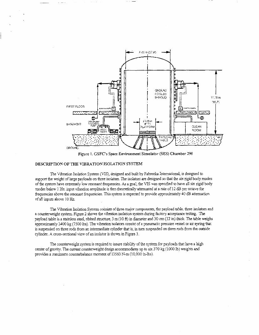
The Vibration Isolation System consists of three major components, the payload table, three isolators and a counterweight system Figqre 2 shows the vibration isolation system during factory acceptaiice testing. The payload table is a stainless steel, ribbed structure, 3 m (1 0 ft) in diameter and 30 cm (12 in) h c k . The table weighs approximately 3400 kg (7500 lbs). The vibration isolators consist of a pneumatic pressure vessel or air spring that is suspended on three rods fiom an intermediate cylinder that is, in turn suspended on three rods from the outside cylinder. A cross-sectional view of an isolator is shown in Figure 3.
The counterweight system is required ta insure stability oithe system for payloads that have a high center of gravity. The current counterweight design accommodates up to six 370 kg (1 000 Ib) weights and provides a maximum counterbalance moment of 13560 N-m (10,000 in-lbs).
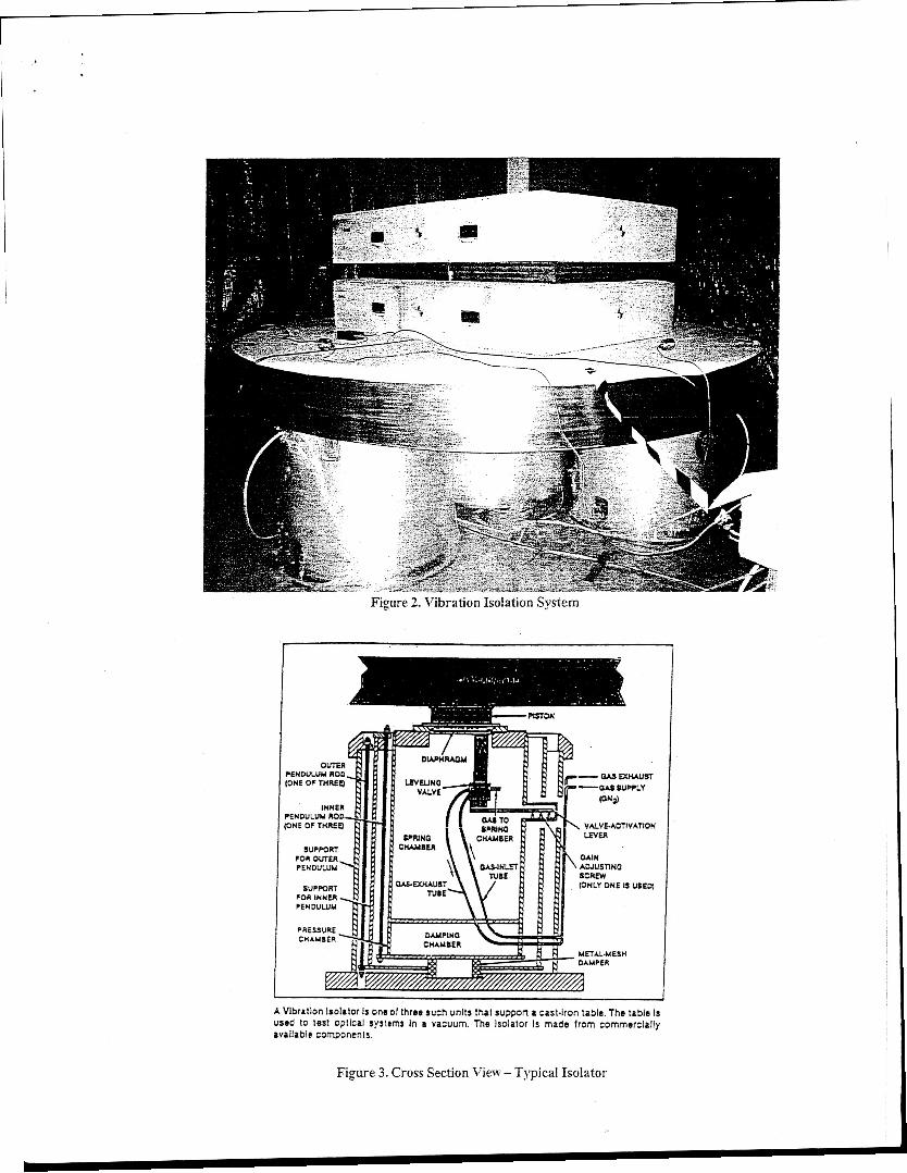
Figure 3. Cross Section View - Typical Isolator
AIR SPRllvG DESIGN
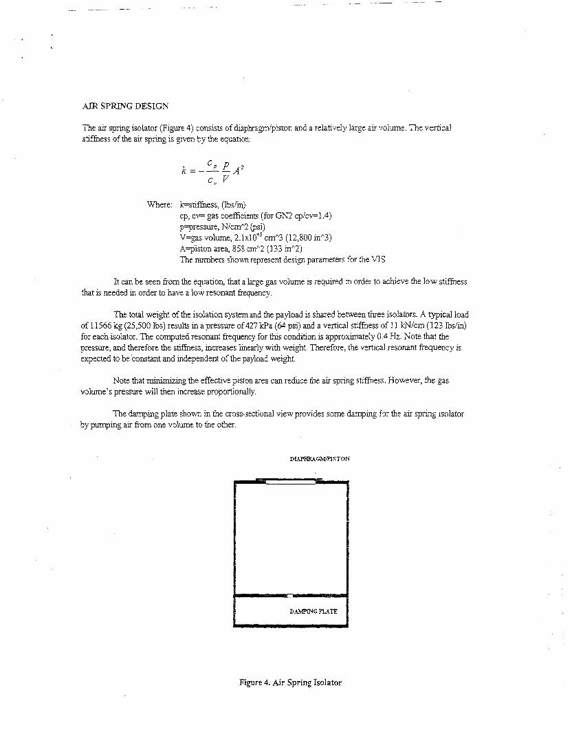
The air spring isolator (Figure 3) consists of diaphra-m’piston and a relatively large air volume. The vertical s m e s s of the air spring is given by the equation:
Where: kstiymess, (lbs/in) cp, CF gas coefficients (for GN2 cp/cv= 1.4) p-pressure, N/cm% (psi) V=gas volume, ~ . I X ~ O + ~ cmA3 (12,800 in”3) A=p%ton area, 858 cm”2 (133 inA2) The numbers shown represent desip parameters for the VI3
It can be seen from the equation, that a large gas volume is required in order to achieve the low stirmess that is needed in order to have a low resonant frequency.
The total weight of the isolation system and the payload is shared bzmeen three isolators. A typical load of 11566 kg (25,500 Ibs) results in a pressure of 427 kPa (64 psi) and a vertical stifhess of 1 1 kN/cm (123 Ibs/in) for each isolator. The computed resonant frequency for t h ~ s condition is approximately 0.4 Hz. Note that the pressure, and therefore the stifhess, increases linearly with weight. Therefore, the vertical resonant frequency is expected to be constant and independent of the payload weight.
Note that minimizing the effective piston area can reduce the air spring stifhess. However, the gas volume’s pressure will then incraase proportionally.
The damping plate shown in the cross-sectional view provides some damping for the air spring isolator by pumping air from one volume to the other.
Figure 4. Air Spring Isolator
L.4TERkL SPRChJG DESIGN
The air spring isolators are suspended on a double set of cantilever rods. Primarilj: gravitational forces determine the lateral sff iess of the isolators. The double set of rods results in an effecrive pendulum length of 174 cm (68.5 in). The resonant frequency for h s pendulum length is approximately 0.4 Hz.
PROBLEMS WITH TABLE DESIGN Ah9 FABRICATION
There were several problems that were related to the original design and fabri-ation of the payload table.
First of all, the table had apparently warped during welding. In order to correct for warping, the top surface had been machined flat. However, other features of the table were not corrected and this contibuted to sipficant problems when we initially tried to pressurize the system.
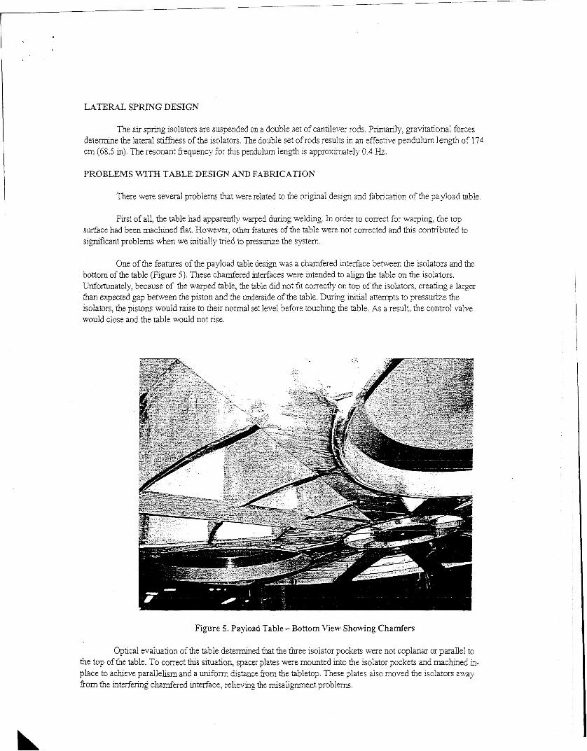
One of the features of the payload table desi@ was i! chamfered interface between the isolators and the bottom of the table (Figure 5). These chamfered interfaces were intended to align the table on the isolators. Unfortunately, because of the warped table, the table did not fit correctly on top of the isolators, creating a larger than expected gap between the piston and the underside of the table. During initial attempts to pressurize the isolators, the pistons would raise to their normal set level before touching the table. As a result, the control valve would close and the table would not rise.
Figure 5. Payload Table - Bottom View Showing Chamfers
Optical evaluation of the table determined that the thee isolator pockets were not coplanar or parallel to the top of the table. To correct t h ~ s situation spacer plates were mounted into the isolator pockets and m a c b e d in- place to achieve parallelism and a u_nifom distance from the tabletop. These plates also moved the isolators away from the interfering chamfered interface, relieving the misalignment problems.
LEAK TESTLTVG RESULTS & CORRECTTVE ACTIONS
Upon arrival at Goddard, it was immediately noted that the flex lines used to pressurize the isolators had sustained sigruficant damage during shipment. Thls problem had occurred because of a failure to properly secure the isolators against relative morion during transportation. As a precaution against fractures in the remaining flex lines, all flex lines were replaced.
The total leak rate of each isolator was to be determined at Goddard by pressurizing the isolator with Helium, while under vacuum, and observing the Helium present in the foreline of the facility’s diffusion pump. A hea\y duty holding fixture that constrained the top of the isolator was designed and built to test the isolators in a 274 cm (9 fi) by 213 cm (7 f?) thermal vacuum test facility. The isolator could be pressurized to 827 kPa ( I 20 psi) with the test fixture.
The leak check setup consisted of a lx105 torr-l/sec calibrated Helium leak attached to a valved chamber port. A leak detector system was connected to a valved port on the diffusion pump foreline. The isolator was loaded into the facility with the supply, exhaust, gauge and sump lines connected to exterior gas lines. The facility was pumped down to high vacuum. The leak detector was run through its calibration sequence using the calibrated leak. The isolator was then pressurized with a Helium supply to 138 Wa (20 psi). The chamber pressure rose rapidly and the diffusion pump’s main valve closed on a pressure interlock.
The facility was vented to atmosphere. An audible hssing was noted from the pipe connections to the isolators. A bubble check with nitrogen confirmed the leaks at the pipe thread fitbngs. The pipe thread fittings were replaced with 1.3 cm (0.5 in) male VCR glands that were welded in place. Further leak detection revealed some pmhole leaks in various weld joints, whch were repaired. The leak testing also revealed a massive leak around the diaphra*m of one isolator. The diaphragm was found to be improperly installed and was replaced and the isolator reassembled. The diaphragms on the other two isolators were also disassembled to inspect for problems and reassembled.
All three isolators were then tested in a makeshift bell jar chamber with a method similar to that previously ciescnied. The leak detected into the vacuum side of the facility was below the specified maximum acceptable leak rate of 1 ~ 1 0 - ~ torr-Vsec He.
The VIS was then assembled in the SES facility. After replacing a failed valve in one of the isolators and adjusting the other two isolator’s valves the system appeared to operate properly.
MODIFICATIONS OF THE ViBRATIOK ISOLATION SYSTEM
A number of modzfications have been made to the vibration isolation system since its delivery to God&-d. These ;na&ficat;,ms have &iince:! the s2feQ znd reIia3iiity ofthe systerr! 2s we!! as iqrsvec! the operation.
Once the VIS was found to operate properly, it was discovered that the control system did not provide a convenient method to depressurize the system and lower the table onto the isolators. To provide this capability, a tee with a manual valve was added to each of the gauge lines. These valves can be opened to depressurize the isolators.
Three Linear Variable Differential Transformers (LVDTs) were added to indicate the height of the table. Three h t switches and a supply shutoff valve were also added to limit the table lift to 1.3 cm (0.5 in). The shutoff valve has a 0.12 cm (3164 in) orifice that controls the rate at which the table would descend if the supply line should lose pressure. An odoffswitch was also added for operator use m an emergency situation.
SYSTEM DY"4MIC TESTING RESULTS
The vibration isolation system has been tested under atmospheric conditions to venfy its dynamic characteristics. The vibration isolation system was assembled in its normal configuration, with a 1360 kg (3000 lb) payload and appropriate counterweight. The total isolated weight equaled 8437 kg ( I 8:600 Ibs).
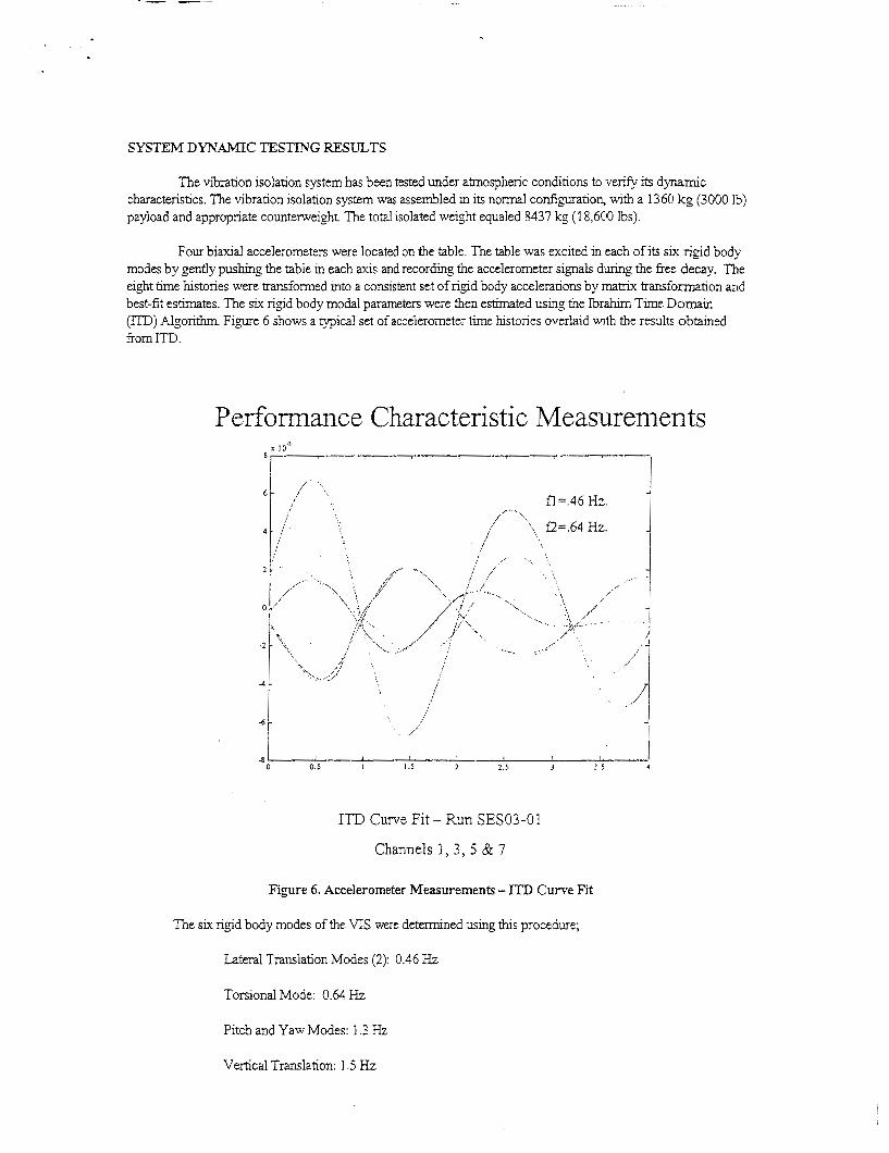
Four biaxial accelerometers were located on the table. The table was excited in each of its six rigid body modes by gently p u s h g the table in each axis and recording the accelerometer signals during the free decay, The eight time hstories were transformed into a consistent set of rigid body acceleranons by matrix transformation and best-fit estimates. The six rigid body modal parameters were then estimated using the Ibrahrm Time Domain (ITD) Algorithm Fipre 6 shows a typical set of accelerometer time histories overlaid wth the results obtained &om ITD .
P
-6 t i 8
0.5 I I . j 2 2 5 3 2 5 4
ITD Curve Fit - Run SES03-01
Channels 1, 3, 5 BL 7
Figure 6. Accelerometer Measurements - ITD Curve Fit
The six rigid body modes of the VIS were determined using this procedure;
Lateral Translation Modes (2): 0.46 F?
Torsional Mode: 0.64 Hz
Pitch and Yaw Modes: 1.3 Hz
Vertical Translation: 1.5 Hz

COlVCLUSION
After correcting a number of design problems, the Vibration Isolation System should prove to have a long useful life. The VIS will provide a sipficantly reduced vibration environment to meet the requirements of hture payloads in the SES facility.