Embed Size (px)
Citation preview
Farrat Isolevel Ltd Balmoral Road, Altrincham, Cheshire, WA15 8HJ, England, UKT. +44 (0) 161 924 1600 F. +44 (0) 161 924 1616 E. [email protected] www.farrat.com
By Atilla Akarcay - Farrat Switzerland, Chris Lister - Farrat Thermal Breaks, and Joe Pemberton - University of Salford.
Balcony Technical Paper v1.0
Want less bounce in your balcony?A technical paper on improving balcony stiffness
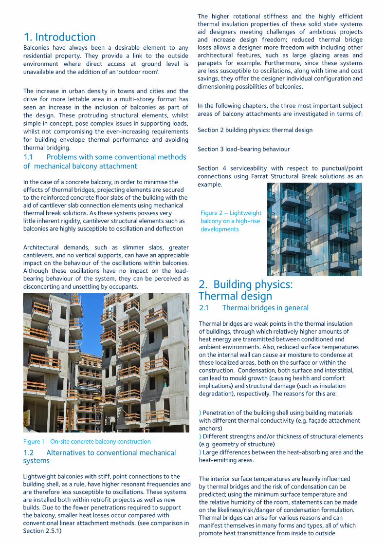
1. Introduction
1.1 Problems with some conventional methods of mechanical balcony attachment In the case of a concrete balcony, in order to minimise the effects of thermal bridges, projecting elements are secured to the reinforced concrete floor slabs of the building with the aid of cantilever slab connection elements using mechanical thermal break solutions. As these systems possess very little inherent rigidity, cantilever structural elements such as balconies are highly susceptible to oscillation and deflection
Architectural demands, such as slimmer slabs, greater cantilevers, and no vertical supports, can have an appreciable impact on the behaviour of the oscillations within balconies. Although these oscillations have no impact on the load-bearing behaviour of the system, they can be perceived as disconcerting and unsettling by occupants.
Figure 1 – On-site concrete balcony construction
Technical
There are materials available in the market which are used in structural connections but have no Accreditation. These are typically materials developed for use in other industries that have not been independently evaluated or tested for use in structural connections in building applications.
Farrat structural thermal breaks are accredited under: • British Board of Agrèment [BBA] Certificated • British Research Establishment [BRE] Certified Thermal Product Scheme • NHBC • BS EN ISO 9001: 2008 [TUV Nord] • BS EN ISO 14001: 2004 [TUV Nord]• Member of the Steel Construction Institute [SCI]
The higher rotational stiffness and the highly efficient thermal insulation properties of these solid state systems aid designers meeting challenges of ambitious projects and increase design freedom; reduced thermal bridge loses allows a designer more freedom with including other architectural features, such as large glazing areas and parapets for example. Furthermore, since these systems are less susceptible to oscillations, along with time and cost savings, they offer the designer individual configuration and dimensioning possibilities of balconies.
In the following chapters, the three most important subject areas of balcony attachments are investigated in terms of: Section 2 building physics: thermal design
Section 3 load-bearing behaviour
Section 4 serviceability with respect to punctual/point connections using Farrat Structural Break solutions as an example.
1.2 Alternatives to conventional mechanical systems Lightweight balconies with stiff, point connections to the building shell, as a rule, have higher resonant frequencies and are therefore less susceptible to oscillations. These systems are installed both within retrofit projects as well as new builds. Due to the fewer penetrations required to support the balcony, smaller heat losses occur compared with conventional linear attachment methods. (see comparison in Section 2.5.1)
2.1 Thermal bridges in general Thermal bridges are weak points in the thermal insulation of buildings, through which relatively higher amounts of heat energy are transmitted between conditioned and ambient environments. Also, reduced surface temperatures on the internal wall can cause air moisture to condense at these localized areas, both on the surface or within the construction. Condensation, both surface and interstitial, can lead to mould growth (causing health and comfort implications) and structural damage (such as insulation degradation), respectively. The reasons for this are:
) Penetration of the building shell using building materials with different thermal conductivity (e.g. façade attachment anchors) ) Different strengths and/or thickness of structural elements (e.g. geometry of structure) ) Large differences between the heat-absorbing area and the heat-emitting areas.
The interior surface temperatures are heavily influenced by thermal bridges and the risk of condensation can be predicted; using the minimum surface temperature and the relative humidity of the room, statements can be made on the likeliness/risk/danger of condensation formulation. Thermal bridges can arise for various reasons and can manifest themselves in many forms and types, all of which promote heat transmittance from inside to outside.
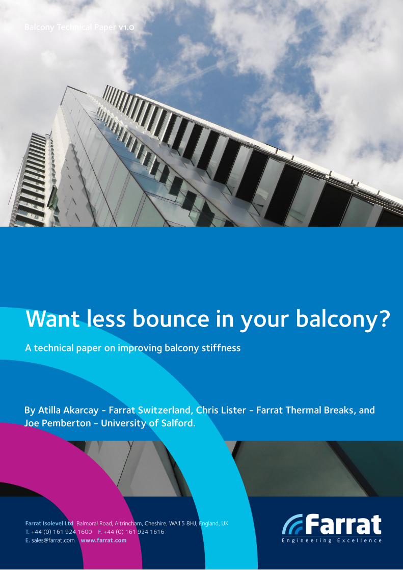
Figure 2 – Lightweight balcony on a high-rise developments
Balconies have always been a desirable element to any residential property. They provide a link to the outside environment where direct access at ground level is unavailable and the addition of an ‘outdoor room’.
The increase in urban density in towns and cities and the drive for more lettable area in a multi-storey format has seen an increase in the inclusion of balconies as part of the design. These protruding structural elements, whilst simple in concept, pose complex issues in supporting loads, whilst not compromising the ever-increasing requirements for building envelope thermal performance and avoiding thermal bridging.
2. Building physics: Thermal design
02
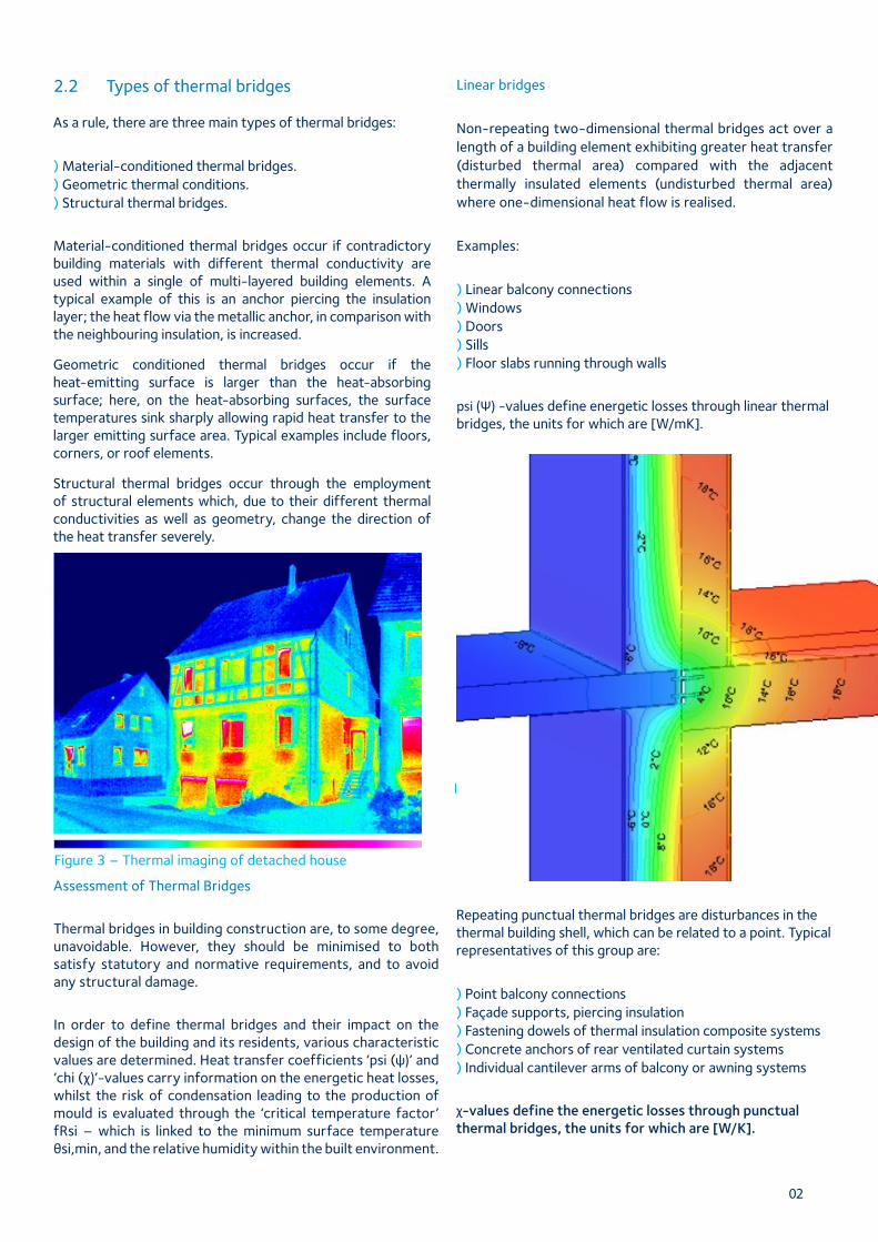
2.2 Types of thermal bridges As a rule, there are three main types of thermal bridges:
) Material-conditioned thermal bridges. ) Geometric thermal conditions. ) Structural thermal bridges.
Material-conditioned thermal bridges occur if contradictory building materials with different thermal conductivity are used within a single of multi-layered building elements. A typical example of this is an anchor piercing the insulation layer; the heat flow via the metallic anchor, in comparison with the neighbouring insulation, is increased.
Geometric conditioned thermal bridges occur if the heat-emitting surface is larger than the heat-absorbing surface; here, on the heat-absorbing surfaces, the surface temperatures sink sharply allowing rapid heat transfer to the larger emitting surface area. Typical examples include floors, corners, or roof elements.
Structural thermal bridges occur through the employment of structural elements which, due to their different thermal conductivities as well as geometry, change the direction of the heat transfer severely.
Figure 3 – Thermal imaging of detached house
Technical
There are materials available in the market which are used in structural connections but have no Accreditation. These are typically materials developed for use in other industries that have not been independently evaluated or tested for use in structural connections in building applications.
Farrat structural thermal breaks are accredited under: • British Board of Agrèment [BBA] Certificated • British Research Establishment [BRE] Certified Thermal Product Scheme • NHBC • BS EN ISO 9001: 2008 [TUV Nord] • BS EN ISO 14001: 2004 [TUV Nord]• Member of the Steel Construction Institute [SCI]
Linear bridges
Non-repeating two-dimensional thermal bridges act over a length of a building element exhibiting greater heat transfer (disturbed thermal area) compared with the adjacent thermally insulated elements (undisturbed thermal area) where one-dimensional heat flow is realised.
Examples:
) Linear balcony connections ) Windows ) Doors ) Sills ) Floor slabs running through walls
psi (Ψ) -values define energetic losses through linear thermal bridges, the units for which are [W/mK].
Assessment of Thermal Bridges
Thermal bridges in building construction are, to some degree, unavoidable. However, they should be minimised to both satisfy statutory and normative requirements, and to avoid any structural damage.
In order to define thermal bridges and their impact on the design of the building and its residents, various characteristic values are determined. Heat transfer coefficients ‘psi (ψ)’ and ‘chi (χ)’-values carry information on the energetic heat losses, whilst the risk of condensation leading to the production of mould is evaluated through the ‘critical temperature factor’ fRsi – which is linked to the minimum surface temperature θsi,min, and the relative humidity within the built environment.
Point Bridges
Repeating punctual thermal bridges are disturbances in the thermal building shell, which can be related to a point. Typical representatives of this group are:
) Point balcony connections ) Façade supports, piercing insulation ) Fastening dowels of thermal insulation composite systems ) Concrete anchors of rear ventilated curtain systems ) Individual cantilever arms of balcony or awning systems
χ-values define the energetic losses through punctual thermal bridges, the units for which are [W/K].
Figure 4 – Calculation of the heat flow on a linear bridge
Summarising the impacts of thermal bridges:
) Increased heat energy loss ) Increased risk of condensation
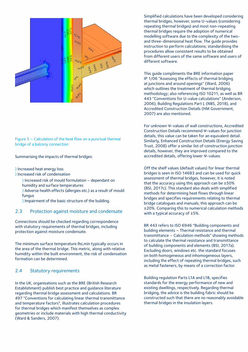
Figure 5 – Calculation of the heat flow on a punctual thermal bridge of a balcony connection
) Increased risk of mould formulation – dependant on humidity and surface temperatures ) Adverse health effects (allergies etc.) as a result of mould fungus ) Impairment of the basic structure of the building.
2.3 Protection against moisture and condensate Connections should be checked regarding correspondence with statutory requirements of thermal bridges, including protection against moisture condensate.
The minimum surface temperature θsi,min typically occurs in the area of the thermal bridge. This metric, along with relative humidity within the built environment, the risk of condensation formation can be determined.
2.4 Statutory requirements
In the UK, organisations such as the BRE (British Research Establishment) publish best practice and guidance literature regarding thermal bridge assessment and calculations. BR 497 “Conventions for calculating linear thermal transmittance and temperature factors”, illustrates calculation procedures for thermal bridges which manifest themselves as complex geometries or include materials with high thermal conductivity (Ward & Sanders, 2007).
Simplified calculations have been developed considering thermal bridges, however, some U-values (considering repeating thermal bridges) and most non-repeating thermal bridges require the adoption of numerical modelling software due to the complexity of the two- and three-dimensional heat flow. The guide provides instruction to perform calculations; standardising the procedures allow consistent results to be obtained from different users of the same software and users of different software.
This guide compliments the BRE information paper IP 1/06 “Assessing the effects of thermal bridging at junctions and around openings” (Ward, 2006) which outlines the treatment of thermal bridging methodology; also referencing ISO 10211, as well as BR 443 “Conventions for U-value calculations” (Anderson, 2006), Building Regulations Part L (NBS, 2018), and Accredited Construction Details (HM Government, 2007) are also mentioned.
For unknown Ψ-values of wall constructions, Accredited Construction Details recommend Ψ-values for junction details, this value can be taken for an equivalent detail. Similarly, Enhanced Construction Details (Energy Saving Trust, 2008) offer a similar list of construction junction details, however, they are improved compared to the accredited details, offering lower Ψ-values.
Off the shelf values (default values) for linear thermal bridges is seen in ISO 14683 and can be used for quick assessment of thermal bridges, however, it is noted that the accuracy using this approach can be ±50% (BSI, 2017c). This standard also deals with simplified methods for determining heat flows through linear bridges and specifies requirements relating to thermal bridge catalogues and manuals; this approach can be ±20%. Comparing this to numerical calculation methods with a typical accuracy of ±5%.
BR 443 refers to ISO 6946 “Building components and building elements – Thermal resistance and thermal transmittance – Calculation methods” showing methods to calculate the thermal resistance and transmittance of building components and elements (BSI, 2017a). Excluding doors, windows etc. the standard focuses on both homogeneous and inhomogeneous layers, including the effect of repeating thermal bridges, such as metal fasteners, by means of a correction factor.
Building regulation Parts L1A and L1B, specifies standards for the energy performance of new and existing dwellings, respectively. Regarding thermal bridging, the advice is the building fabric should be constructed such that there are no reasonably avoidable thermal bridges in the insulation layers.
2.5 Protection against moisture and condensate Structural thermal breaks minimise the impact of thermal bridges such as balconies and other penetrative elements; the high compressive strength and low thermal conductivity, allow application within steel connections and reduces high thermal losses.
Due to the high compressive strength and low deformation behaviour, balconies, awnings, and projecting roofs can be attached to load-bearing structural elements of a building using very few anchorage points.
Through these strictly limited disturbances of the building envelope – compared to conventional concrete balcony slab connectors – only point/punctual thermal bridges are formed, which, due to the small number of anchorage points, leads to significant reductions in heat loss.
In addition to the low thermal transmittance, the system also offers very high rotational stiffness – allowing the designer to realise longer, low vibration balconies.
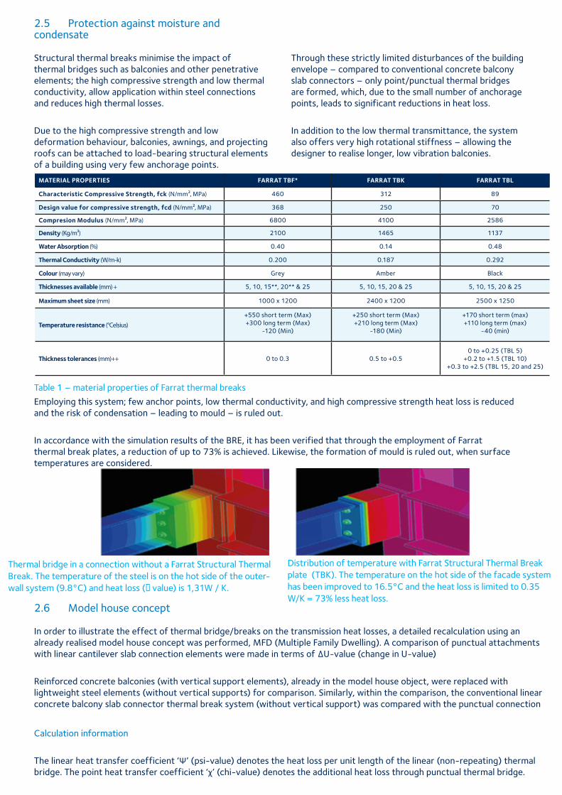
MATERIAL PROPERTIES FARRAT TBF* FARRAT TBK FARRAT TBL
Characteristic Compressive Strength, fck (N/mm², MPa) 460 312 89
Design value for compressive strength, fcd (N/mm², MPa) 368 250 70
Compresion Modulus (N/mm², MPa) 6800 4100 2586
Density (Kg/m³) 2100 1465 1137
Water Absorption (%) 0.40 0.14 0.48
Thermal Conductivity (W/m-k) 0.200 0.187 0.292
Colour (may vary) Grey Amber Black
Thicknesses available (mm) + 5, 10, 15**, 20** & 25 5, 10, 15, 20 & 25 5, 10, 15, 20 & 25
Maximum sheet size (mm) 1000 x 1200 2400 x 1200 2500 x 1250
Temperature resistance (°Celsius)
+550 short term (Max)+300 long term (Max)
-120 (Min)
+250 short term (Max)+210 long term (Max)
-180 (Min)
+170 short term (max)+110 long term (max)
-40 (min)
Thickness tolerances (mm)++ 0 to 0.3 0.5 to +0.50 to +0.25 (TBL 5)
+0.2 to +1.5 (TBL 10)+0.3 to +2.5 (TBL 15, 20 and 25)
Table 1 – material properties of Farrat thermal breaks
Employing this system; few anchor points, low thermal conductivity, and high compressive strength heat loss is reduced and the risk of condensation – leading to mould – is ruled out.
In accordance with the simulation results of the BRE, it has been verified that through the employment of Farrat thermal break plates, a reduction of up to 73% is achieved. Likewise, the formation of mould is ruled out, when surface temperatures are considered.
Thermal bridge in a connection without a Farrat Structural Thermal Break. The temperature of the steel is on the hot side of the outer-wall system (9.8°C) and heat loss (χ value) is 1,31W / K.
Distribution of temperature with Farrat Structural Thermal Break plate (TBK). The temperature on the hot side of the facade system has been improved to 16.5°C and the heat loss is limited to 0.35 W/K = 73% less heat loss.
2.6 Model house concept In order to illustrate the effect of thermal bridge/breaks on the transmission heat losses, a detailed recalculation using an already realised model house concept was performed, MFD (Multiple Family Dwelling). A comparison of punctual attachments with linear cantilever slab connection elements were made in terms of ∆U-value (change in U-value)
Reinforced concrete balconies (with vertical support elements), already in the model house object, were replaced with lightweight steel elements (without vertical supports) for comparison. Similarly, within the comparison, the conventional linear concrete balcony slab connector thermal break system (without vertical support) was compared with the punctual connection
Calculation information
The linear heat transfer coefficient ‘Ψ’ (psi-value) denotes the heat loss per unit length of the linear (non-repeating) thermal bridge. The point heat transfer coefficient ‘χ’ (chi-value) denotes the additional heat loss through punctual thermal bridge.
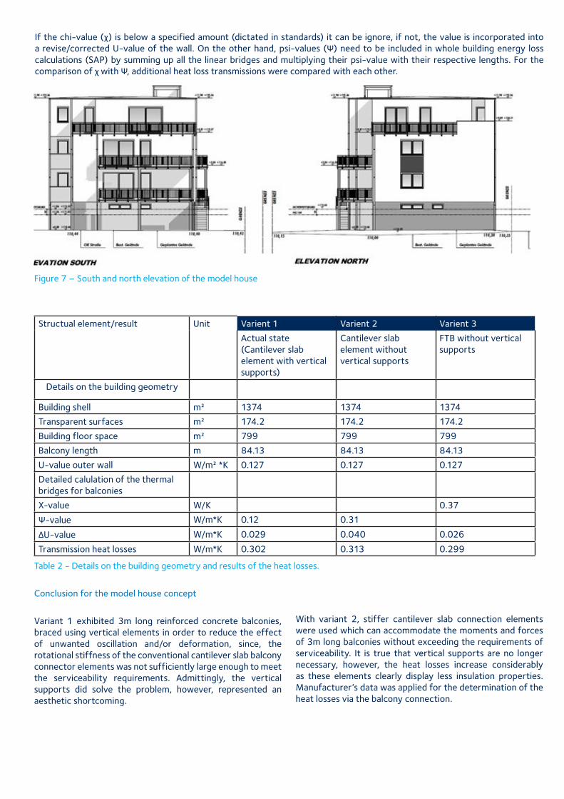
If the chi-value (χ) is below a specified amount (dictated in standards) it can be ignore, if not, the value is incorporated into a revise/corrected U-value of the wall. On the other hand, psi-values (Ψ) need to be included in whole building energy loss calculations (SAP) by summing up all the linear bridges and multiplying their psi-value with their respective lengths. For the comparison of χ with Ψ, additional heat loss transmissions were compared with each other.
Figure 7 – South and north elevation of the model house
Structual element/result Unit Varient 1 Varient 2 Varient 3
Actual state (Cantilever slab element with vertical supports)
Cantilever slab element without vertical supports
FTB without vertical supports
Details on the building geometry
Building shell m² 1374 1374 1374
Transparent surfaces m² 174.2 174.2 174.2
Building floor space m² 799 799 799
Balcony length m 84.13 84.13 84.13
U-value outer wall W/m² *K 0.127 0.127 0.127
Detailed calulation of the thermal bridges for balconies
X-value W/K 0.37
Ψ-value W/m*K 0.12 0.31
ΔU-value W/m*K 0.029 0.040 0.026
Transmission heat losses W/m*K 0.302 0.313 0.299 Table 2 - Details on the building geometry and results of the heat losses.
Conclusion for the model house concept
Variant 1 exhibited 3m long reinforced concrete balconies, braced using vertical elements in order to reduce the effect of unwanted oscillation and/or deformation, since, the rotational stiffness of the conventional cantilever slab balcony connector elements was not sufficiently large enough to meet the serviceability requirements. Admittingly, the vertical supports did solve the problem, however, represented an aesthetic shortcoming.
With variant 2, stiffer cantilever slab connection elements were used which can accommodate the moments and forces of 3m long balconies without exceeding the requirements of serviceability. It is true that vertical supports are no longer necessary, however, the heat losses increase considerably as these elements clearly display less insulation properties. Manufacturer’s data was applied for the determination of the heat losses via the balcony connection.
Variant 3, prefabricated balcony elements have been depicted with punctual attachments (for comparison purposes the same load and moment distribution as in variant 1 and 2 was assumed), fitted with 25mm thick Farrat thermal break plates as thermal separation. Due to the low thermal conductivity and high compressive strength, heat losses are reduced considerably whilst low deformation/displacement is achieved.
Results show that adopting the stiffer punctual balcony support system, longer, unsupported balconies can be designed. With this, the undesired oscillations are ruled out and the requirements for serviceability are satisfied. For the purpose of showing exemplar performance the reduced thermal losses for Farrat thermal breaks comply with the certification for the Passive House standard.
Overview of thermal bridging
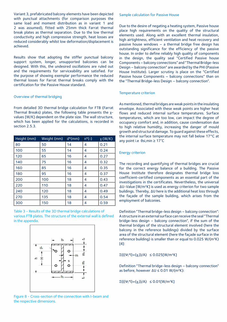
From detailed 3D thermal bridge calculation for FTB (Farrat Thermal Breaks) plates, the following table presents the χ- values [W/K] dependent on the plate size. The wall structure, which has been applied for the calculations, is recorded in section 2.5.3.
Height (mm) Weight (mm) d*(mm) n*(-) χ (W/K)
80 50 14 4 0.21
100 55 14 4 0.24
120 65 16 4 0.27
140 75 16 4 0.32
160 85 16 4 0.35
180 95 16 4 0.37
200 100 18 4 0.43
220 110 18 4 0.47
240 120 18 4 0.49
270 135 18 4 0.54
300 150 18 4 0.59 Table 3 - Results of the 3D thermal bridge calculations of various FTB plates. The structure of the external wall is defined in the appendix.
Figure 8 - Cross-section of the connection with I-beam and the respective dimensions.
Sample calculation for Passive House
Due to the desire of negating a heating system, Passive house place high requirements on the quality of the structural elements used. Along with an excellent thermal insulation, high airtightness, efficient ventilation and heat recovery and passive house windows – a thermal bridge free design has outstanding significance for the efficiency of the passive house. In order to define reliably high quality of components in the design, the quality seal “Certified Passive house Components – balcony connections” and “Thermal Bridge-less Design – balcony connection” are awarded by the PHI (Passive House Institute). Larger scrutiny is place on the “Certified Passive house Components – balcony connections” than on the “Thermal Bridge-less Design – balcony connection”.
Temperature criterion
As mentioned, thermal bridges are weak points in the insulating envelope. Associated with these weak points are higher heat flows and reduced internal surface temperatures. Surface temperatures, which are too low, can impact the degree of occupancy comfort and, in addition, cause condensation due to high relative humidity, increasing the danger of mould growth and structural damage. To guard against these effects, the internal surface temperature may not fall below 17°C at any point i.e θsi,min ≥ 17˚C
Energy criterion
The recording and quantifying of thermal bridges are crucial for the correct energy balance of a building. The Passive House Institute therefore designates thermal bridge loss coefficient-certified components as an essential part of the investigations in the certificates. Nevertheless, the universal ∆U-Value [W/m²K] is used as energy criterion for two sample buildings. Thereby, ∆U here is the additional heat loss through the façade of the sample building, which arises from the employment of balconies.
Definition “Thermal bridge-less design – balcony connection”: A structure in an external surface can receive the seal “Thermal bridge-less design – balcony connection”, if the sum of the thermal bridges of the structural element involved (here the balcony in the reference buildings) divided by the surface area of the structural element (here the façade surface in the reference building) is smaller than or equal to 0.025 W/(m²K) [4]:
∑(((Ψj*l)+(χ j))/A) ≤ 0.025[W/m²K]
Definition “Thermal bridge-less design – balcony connection” as before, however ∆U ≤ 0.01 W/(m²K):
∑(((Ψj*l)+(χ j))/A) ≤ 0.01[W/m²K]
Number Material λ- (W/mK)
Thickness
1 Reinforced concrete floor 2.3 250mm
2 Impact sound insulation 0.35 40mm
3 Screed 1.4 60mm
4 Reinforced concrete (wall)
2.3 200mm
5 Thermal insulation 0.035 250mm
6 Steel (IPE 140) 50 140*73mm
7 Stainless steel (load distribution plate)
15 140*75*15 mm
8 TBK 0.187 140*75*25 mm
9 Interior plaster 0.51 15
10 Exterior rendering 0.7 10
*four bolts with diameter 18 mm and length 140 mm were assumed for the connection
*the required IPE 140 beam was modelled for worst case conditions as massive structural element (140*73mm)
Where:
Ψ - thermal bridge loss coefficient (linear TB) [W/mK]
l - length of the thermal bridge [m]
χ - thermal bridge loss coefficient (punctual TB) [W/K]
A - reference surface (e.g. outer wall, roof...) [m²]
j - index, which runs over all relevant elements in the surface concerned
Basis of calculation and constraints
The criteria of the Passive House certification basically refer to two different reference buildings:
Reference building 1: terraced house:
Reference budiling 2: Apartment complex
Façade area: 184.28m² 2557.11m²
Lenth of balconies 8m 248m
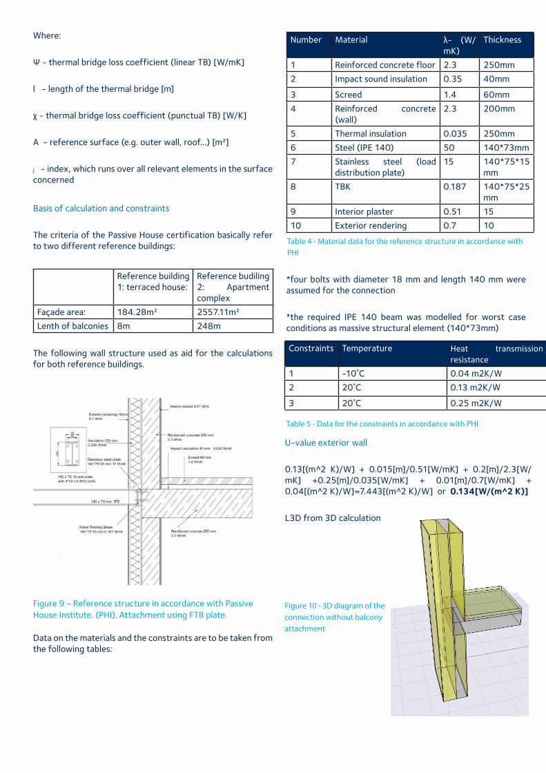
The following wall structure used as aid for the calculations for both reference buildings.
Figure 9 - Reference structure in accordance with Passive House Institute. (PHI). Attachment using FTB plate.
Data on the materials and the constraints are to be taken from the following tables:
Table 4 - Material data for the reference structure in accordance with PHI
Constraints Temperature Heat transmission resistance
1 -10˚C 0.04 m2K/W
2 20˚C 0.13 m2K/W
3 20˚C 0.25 m2K/W
Table 5 - Data for the constraints in accordance with PHI
U-value exterior wall
0.13[(m^2 K)/W] + 0.015[m]/0.51[W/mK] + 0.2[m]/2.3[W/mK] +0.25[m]/0.035[W/mK] + 0.01[m]/0.7[W/mK] + 0.04[(m^2 K)/W]=7.443[(m^2 K)/W] or 0.134[W/(m^2 K)]
L3D from 3D calculation
Figure 10 - 3D diagram of the connection without balcony attachment
Constraints Temperature Heat transmission resistance
1 -10˚C 0.04 m2K/W
2 20˚C 0.13 m2K/W
3 20˚C 0.25 m2K/W
Heat flow (W/m) Delta T (K) Depth of the model (m)
L3D (W/K) Minimum surface temperature (˚C)
Without balconies 13.104 30 1 0.437 19.5
With IPE 140 19.65 30 1 0.655 17.6
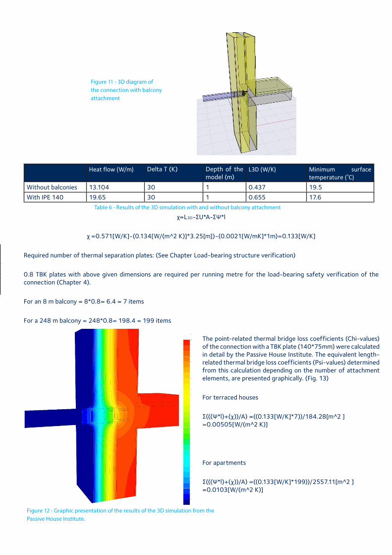
Figure 11 - 3D diagram of the connection with balcony attachment
Table 6 - Results of the 3D simulation with and without balcony attachment
χ=L3D-∑U*A-∑Ψ*l
χ =0.571[W/K]-(0.134[W/(m^2 K)]*3.25[m])-(0.0021[W/mK]*1m)=0.133[W/K]
Required number of thermal separation plates: (See Chapter Load-bearing structure verification)
0.8 TBK plates with above given dimensions are required per running metre for the load-bearing safety verification of the connection (Chapter 4).
For an 8 m balcony = 8*0.8= 6.4 = 7 items
For a 248 m balcony = 248*0.8= 198.4 = 199 items
Figure 12 - Graphic presentation of the results of the 3D simulation from the Passive House Institute.
The point-related thermal bridge loss coefficients (Chi-values) of the connection with a TBK plate (140*75mm) were calculated in detail by the Passive House Institute. The equivalent length-related thermal bridge loss coefficients (Psi-values) determined from this calculation depending on the number of attachment elements, are presented graphically. (Fig. 13)
For terraced houses
∑(((Ψ*l)+(χ))/A) =((0.133[W/K]*7))/184.28[m^2 ] =0.00505[W/(m^2 K)]
For apartments
∑(((Ψ*l)+(χ))/A) =((0.133[W/K]*199))/2557.11[m^2 ] =0.0103[W/(m^2 K)]
Conclusions for energy criterion
Reference building Façade area (m2) Balcony length (m) Number of attachments
χ-value (W/K) ΔU (W/m2K)
Terraced house 184.28 8 7 0.133 0.005<=0.01
Appartment complex 2557.11 248 199 0.133 0.0103<=0.01
Table 7 - The summary of both reference buildings and results
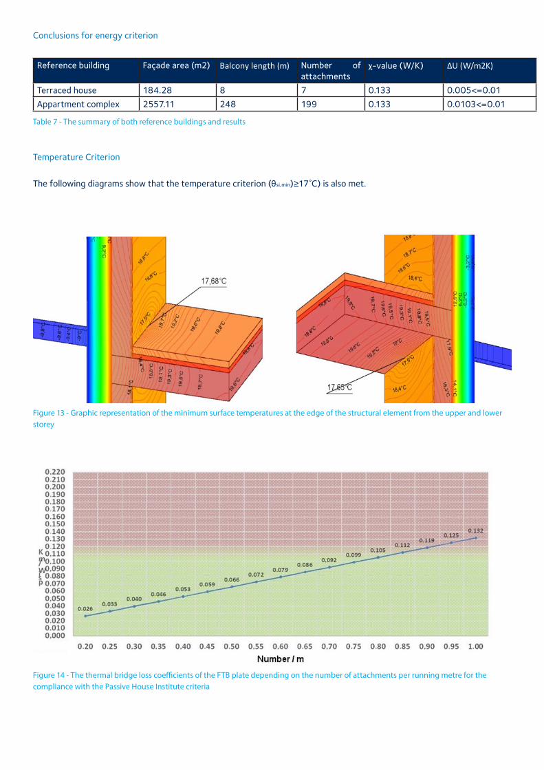
Temperature Criterion
The following diagrams show that the temperature criterion (θsi,min)≥17˚C) is also met.
Figure 13 - Graphic representation of the minimum surface temperatures at the edge of the structural element from the upper and lower storey
Figure 14 - The thermal bridge loss coefficients of the FTB plate depending on the number of attachments per running metre for the compliance with the Passive House Institute criteria
Thermal building physics concolusion
The low thermal conductivity as well as the high compressive strength enable the designer to attach structural elements or sunroofs using a small number of penetrations in the building envelope.
The limiting values of the normative principles, regarding internal surface temperatures and hygienic requirements, are observed and undercut.
Consequently, balcony connections with FTB plates produce even smaller heat losses via the attachment points in comparison with conventional systems. Thereby, not only can heat losses be reduced but undesirable vertical supports can also be negated.
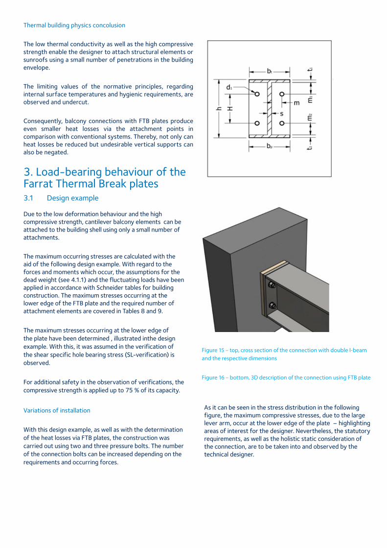
3. Load-bearing behaviour of the Farrat Thermal Break plates3.1 Design example Due to the low deformation behaviour and the high compressive strength, cantilever balcony elements can be attached to the building shell using only a small number of attachments.
The maximum occurring stresses are calculated with the aid of the following design example. With regard to the forces and moments which occur, the assumptions for the dead weight (see 4.1.1) and the fluctuating loads have been applied in accordance with Schneider tables for building construction. The maximum stresses occurring at the lower edge of the FTB plate and the required number of attachment elements are covered in Tables 8 and 9.
The maximum stresses occurring at the lower edge of the plate have been determined , illustrated inthe design example. With this, it was assumed in the verification of the shear specific hole bearing stress (SL-verification) is observed.
For additional safety in the observation of verifications, the compressive strength is applied up to 75 % of its capacity.
Variations of installation
With this design example, as well as with the determination of the heat losses via FTB plates, the construction was carried out using two and three pressure bolts. The number of the connection bolts can be increased depending on the requirements and occurring forces.
Figure 15 – top, cross section of the connection with double I-beam and the respective dimensions
Figure 16 – bottom, 3D description of the connection using FTB plate
As it can be seen in the stress distribution in the following figure, the maximum compressive stresses, due to the large lever arm, occur at the lower edge of the plate – highlighting areas of interest for the designer. Nevertheless, the statutory requirements, as well as the holistic static consideration of the connection, are to be taken into and observed by the technical designer.
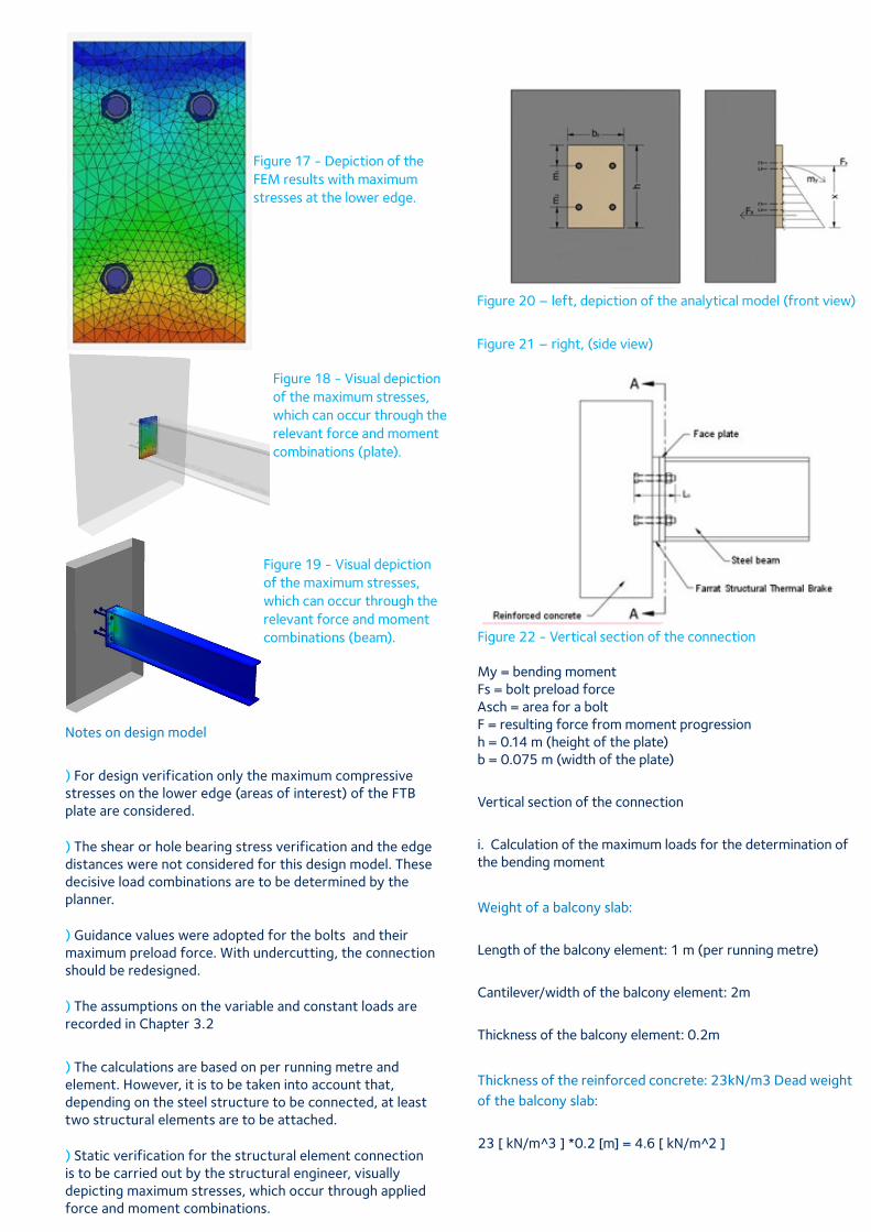
Figure 17 - Depiction of the FEM results with maximum stresses at the lower edge.
Notes on design model
) For design verification only the maximum compressive stresses on the lower edge (areas of interest) of the FTB plate are considered. ) The shear or hole bearing stress verification and the edge distances were not considered for this design model. These decisive load combinations are to be determined by the planner. ) Guidance values were adopted for the bolts and their maximum preload force. With undercutting, the connection should be redesigned. ) The assumptions on the variable and constant loads are recorded in Chapter 3.2
) The calculations are based on per running metre and element. However, it is to be taken into account that, depending on the steel structure to be connected, at least two structural elements are to be attached. ) Static verification for the structural element connection is to be carried out by the structural engineer, visually depicting maximum stresses, which occur through applied force and moment combinations.
Figure 18 - Visual depiction of the maximum stresses, which can occur through the relevant force and moment combinations (plate).
Design example
Figure 20 – left, depiction of the analytical model (front view)
Figure 21 – right, (side view)
Figure 22 - Vertical section of the connection
My = bending moment Fs = bolt preload force Asch = area for a bolt F = resulting force from moment progression h = 0.14 m (height of the plate) b = 0.075 m (width of the plate)
Vertical section of the connection
i. Calculation of the maximum loads for the determination of the bending moment
Weight of a balcony slab:
Length of the balcony element: 1 m (per running metre)
Cantilever/width of the balcony element: 2m
Thickness of the balcony element: 0.2m
Thickness of the reinforced concrete: 23kN/m3 Dead weight of the balcony slab:
23 [ kN/m^3 ] *0.2 [m] = 4.6 [ kN/m 2̂ ]
Figure 19 - Visual depiction of the maximum stresses, which can occur through the relevant force and moment combinations (beam).
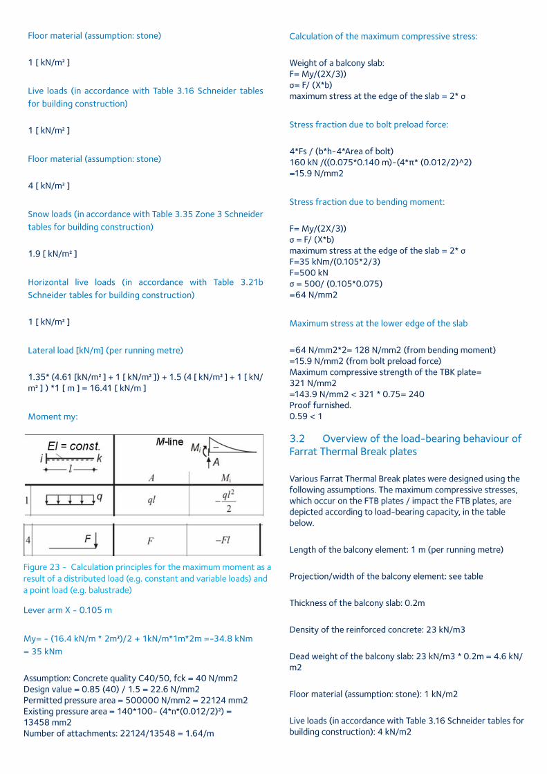
Figure 20 – left, depiction of the analytical model (front view)
Figure 21 – right, (side view)
Figure 22 - Vertical section of the connection
Floor material (assumption: stone)
1 [ kN/m2 ]
Live loads (in accordance with Table 3.16 Schneider tables for building construction)
1 [ kN/m2 ]
Floor material (assumption: stone)
4 [ kN/m2 ]
Snow loads (in accordance with Table 3.35 Zone 3 Schneider tables for building construction)
1.9 [ kN/m2 ]
Horizontal live loads (in accordance with Table 3.21b Schneider tables for building construction)
1 [ kN/m2 ]
Lateral load [kN/m] (per running metre)
1.35* (4.61 [kN/m2 ] + 1 [ kN/m2 ]) + 1.5 (4 [ kN/m2 ] + 1 [ kN/m2 ] ) *1 [ m ] = 16.41 [ kN/m ]
Moment my:
Figure 23 - Calculation principles for the maximum moment as a result of a distributed load (e.g. constant and variable loads) and a point load (e.g. balustrade)
Lever arm X - 0.105 m
My= - (16.4 kN/m * 2m2)/2 + 1kN/m*1m*2m =-34.8 kNm = 35 kNm
Assumption: Concrete quality C40/50, fck = 40 N/mm2 Design value = 0.85 (40) / 1.5 = 22.6 N/mm2 Permitted pressure area = 500000 N/mm2 = 22124 mm2 Existing pressure area = 140*100- (4*n*(0.012/2)2) = 13458 mm2 Number of attachments: 22124/13548 = 1.64/m
Calculation of the maximum compressive stress:
Weight of a balcony slab: F= My/(2X/3)) σ= F/ (X*b) maximum stress at the edge of the slab = 2* σ
Stress fraction due to bolt preload force:
4*Fs / (b*h-4*Area of bolt) 160 kN /((0.075*0.140 m)-(4*π* (0.012/2) 2̂) =15.9 N/mm2
Stress fraction due to bending moment:
F= My/(2X/3)) σ = F/ (X*b) maximum stress at the edge of the slab = 2* σ F=35 kNm/(0.105*2/3) F=500 kN σ = 500/ (0.105*0.075) =64 N/mm2
Maximum stress at the lower edge of the slab
=64 N/mm2*2= 128 N/mm2 (from bending moment) =15.9 N/mm2 (from bolt preload force) Maximum compressive strength of the TBK plate= 321 N/mm2 =143.9 N/mm2 < 321 * 0.75= 240 Proof furnished. 0.59 < 1
3.2 Overview of the load-bearing behaviour of Farrat Thermal Break plates
Various Farrat Thermal Break plates were designed using the following assumptions. The maximum compressive stresses, which occur on the FTB plates / impact the FTB plates, are depicted according to load-bearing capacity, in the table below.
Length of the balcony element: 1 m (per running metre)
Projection/width of the balcony element: see table
Thickness of the balcony slab: 0.2m
Density of the reinforced concrete: 23 kN/m3
Dead weight of the balcony slab: 23 kN/m3 * 0.2m = 4.6 kN/m2
Floor material (assumption: stone): 1 kN/m2
Live loads (in accordance with Table 3.16 Schneider tables for building construction): 4 kN/m2
Snow loads (in accordance with Table 3.35 Zone 3 Schneider tables for building construction)
Horizontal live loads (in accordance with Table 3.21b Schneider tables for building construction) 1 kN/m2
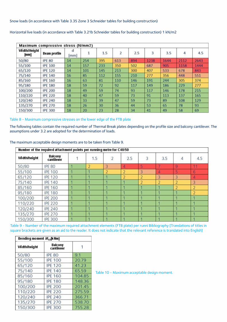
Table 8 - Maximum compressive stresses on the lower edge of the FTB plate
The following tables contain the required number of Thermal Break plates depending on the profile size and balcony cantilever. The assumptions under 3.2 are adopted for the determination of loads.
The maximum acceptable design moments are to be taken from Table 9.
Table 9 - Number of the maximum required attachment elements (FTB plate) per runni Bibliography [Translations of titles in square brackets are given as an aid to the reader. It does not indicate that the relevant reference is translated into English]
Table 10 - Maximum acceptable design moment.
Load-bearing behaviour
Along with the thermal properties, mechanical properties such as high compressive strength and slight deformation behaviour, play an important role with the reduction of transmission heat loss.
The high load-bearing capacities offer the designer the option of securing cantilever structural elements (such as balconies and brise soleil) using a smaller number of penetrations into the building envelope.
For connections with above-average long balconies, the structural safety and the serviceability verification can be satisfied without additional supports.
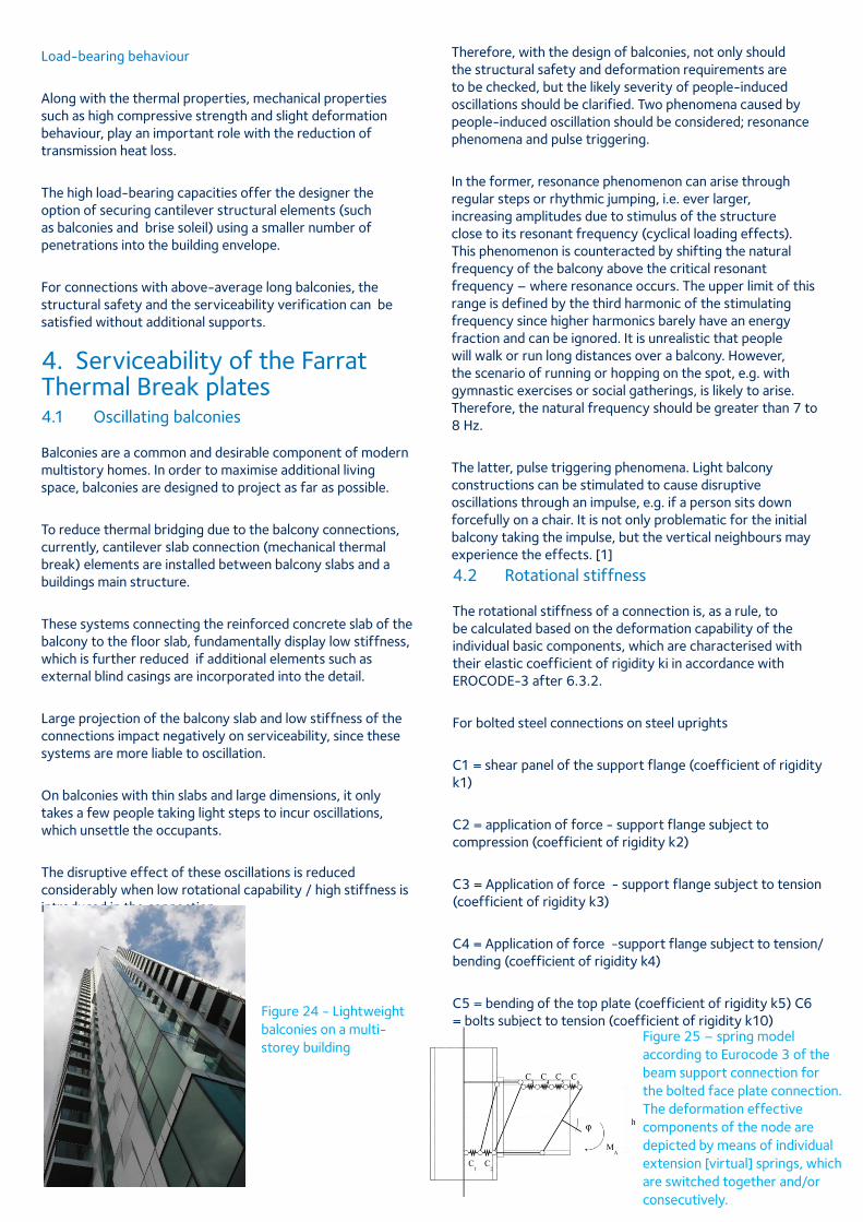
4. Serviceability of the Farrat Thermal Break plates4.1 Oscillating balconies Balconies are a common and desirable component of modern multistory homes. In order to maximise additional living space, balconies are designed to project as far as possible.
To reduce thermal bridging due to the balcony connections, currently, cantilever slab connection (mechanical thermal break) elements are installed between balcony slabs and a buildings main structure.
These systems connecting the reinforced concrete slab of the balcony to the floor slab, fundamentally display low stiffness, which is further reduced if additional elements such as external blind casings are incorporated into the detail.
Large projection of the balcony slab and low stiffness of the connections impact negatively on serviceability, since these systems are more liable to oscillation.
On balconies with thin slabs and large dimensions, it only takes a few people taking light steps to incur oscillations, which unsettle the occupants.
The disruptive effect of these oscillations is reduced considerably when low rotational capability / high stiffness is introduced in the connection.
Figure 24 - Lightweight balconies on a multi-storey building
Therefore, with the design of balconies, not only should the structural safety and deformation requirements are to be checked, but the likely severity of people-induced oscillations should be clarified. Two phenomena caused by people-induced oscillation should be considered; resonance phenomena and pulse triggering.
In the former, resonance phenomenon can arise through regular steps or rhythmic jumping, i.e. ever larger, increasing amplitudes due to stimulus of the structure close to its resonant frequency (cyclical loading effects). This phenomenon is counteracted by shifting the natural frequency of the balcony above the critical resonant frequency – where resonance occurs. The upper limit of this range is defined by the third harmonic of the stimulating frequency since higher harmonics barely have an energy fraction and can be ignored. It is unrealistic that people will walk or run long distances over a balcony. However, the scenario of running or hopping on the spot, e.g. with gymnastic exercises or social gatherings, is likely to arise. Therefore, the natural frequency should be greater than 7 to 8 Hz.
The latter, pulse triggering phenomena. Light balcony constructions can be stimulated to cause disruptive oscillations through an impulse, e.g. if a person sits down forcefully on a chair. It is not only problematic for the initial balcony taking the impulse, but the vertical neighbours may experience the effects. [1]
4.2 Rotational stiffness The rotational stiffness of a connection is, as a rule, to be calculated based on the deformation capability of the individual basic components, which are characterised with their elastic coefficient of rigidity ki in accordance with EROCODE-3 after 6.3.2.
For bolted steel connections on steel uprights
C1 = shear panel of the support flange (coefficient of rigidity k1)
C2 = application of force - support flange subject to compression (coefficient of rigidity k2)
C3 = Application of force - support flange subject to tension (coefficient of rigidity k3)
C4 = Application of force -support flange subject to tension/bending (coefficient of rigidity k4)
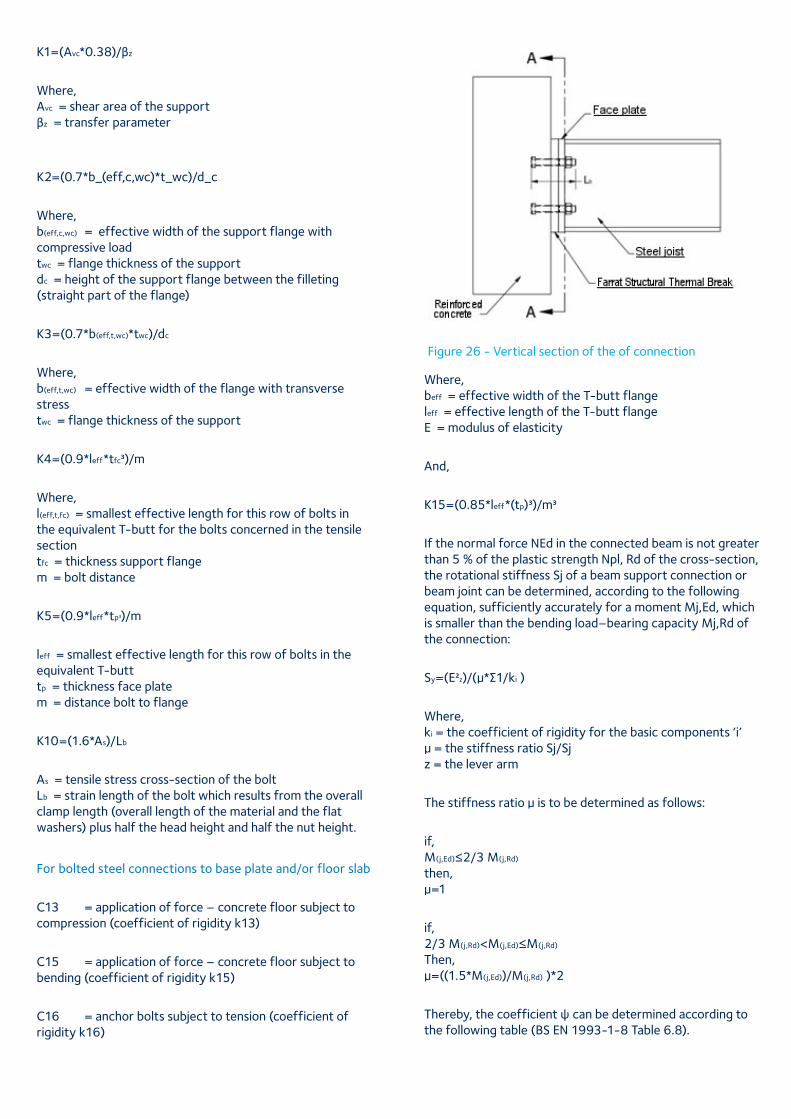
C5 = bending of the top plate (coefficient of rigidity k5) C6 = bolts subject to tension (coefficient of rigidity k10)
Figure 25 – spring model according to Eurocode 3 of the beam support connection for the bolted face plate connection. The deformation effective components of the node are depicted by means of individual extension [virtual] springs, which are switched together and/or consecutively.
K1=(Avc*0.38)/βz
Where, Avc = shear area of the support βz = transfer parameter
K2=(0.7*b_(eff,c,wc)*t_wc)/d_c
Where, b(eff,c,wc) = effective width of the support flange with compressive load twc = flange thickness of the support dc = height of the support flange between the filleting (straight part of the flange)
K3=(0.7*b(eff,t,wc)*twc)/dc
Where, b(eff,t,wc) = effective width of the flange with transverse stress twc = flange thickness of the support
K4=(0.9*leff*tfc3)/m
Where, l(eff,t,fc) = smallest effective length for this row of bolts in the equivalent T-butt for the bolts concerned in the tensile section tfc = thickness support flange m = bolt distance
K5=(0.9*leff*tp3)/m
leff = smallest effective length for this row of bolts in the equivalent T-butt tp = thickness face plate m = distance bolt to flange
K10=(1.6*As)/Lb
As = tensile stress cross-section of the bolt Lb = strain length of the bolt which results from the overall clamp length (overall length of the material and the flat washers) plus half the head height and half the nut height.
For bolted steel connections to base plate and/or floor slab
C13 = application of force – concrete floor subject to compression (coefficient of rigidity k13)
C15 = application of force – concrete floor subject to bending (coefficient of rigidity k15)
C16 = anchor bolts subject to tension (coefficient of rigidity k16)
Figure 26 - Vertical section of the of connection
Where, beff = effective width of the T-butt flange leff = effective length of the T-butt flange E = modulus of elasticity
And,
K15=(0.85*leff*(tp)3)/m3
If the normal force NEd in the connected beam is not greater than 5 % of the plastic strength Npl, Rd of the cross-section, the rotational stiffness Sj of a beam support connection or beam joint can be determined, according to the following equation, sufficiently accurately for a moment Mj,Ed, which is smaller than the bending load–bearing capacity Mj,Rd of the connection:
Sy=(E2z)/(μ*∑1/ki )
Where, ki = the coefficient of rigidity for the basic components ‘i’ μ = the stiffness ratio Sj/Sj z = the lever arm
The stiffness ratio μ is to be determined as follows:
if, M(j,Ed)≤2/3 M(j,Rd) then, μ=1
if, 2/3 M(j,Rd)<M(j,Ed)≤M(j,Rd) Then, μ=((1.5*M(j,Ed))/M(j,Rd) )*2
Thereby, the coefficient ψ can be determined according to the following table (BS EN 1993-1-8 Table 6.8).
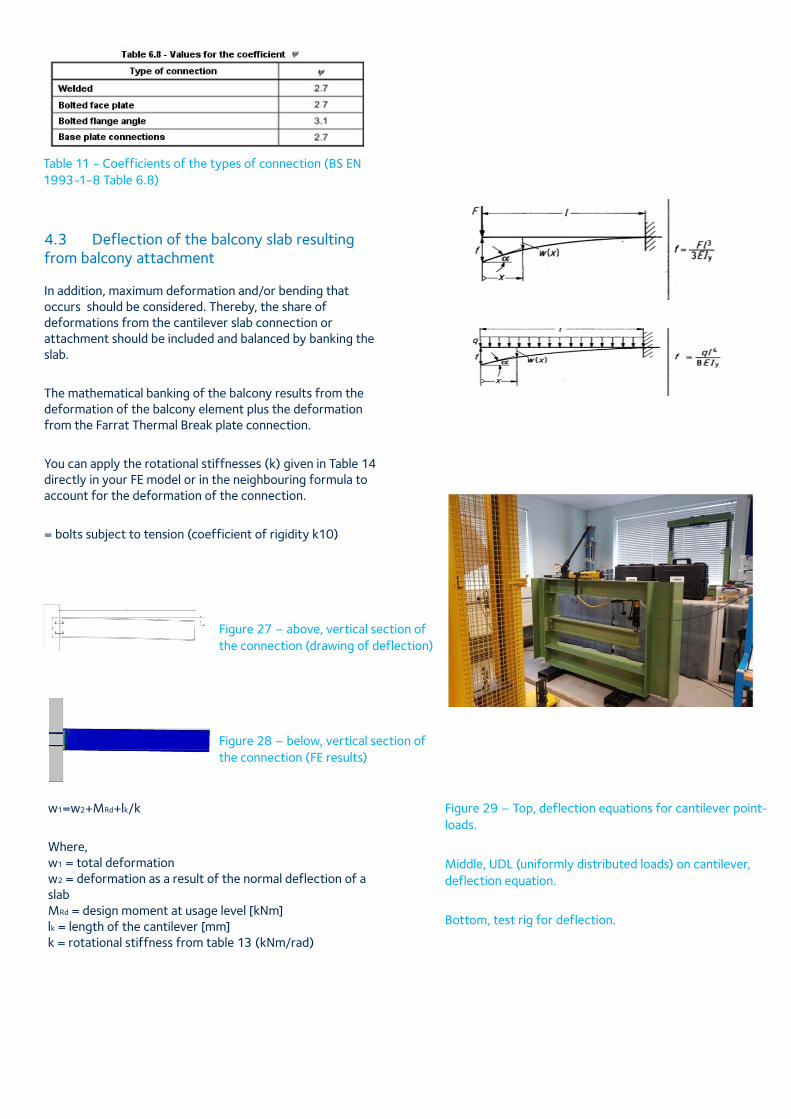
Table 11 - Coefficients of the types of connection (BS EN 1993-1-8 Table 6.8)
4.3 Deflection of the balcony slab resulting from balcony attachment In addition, maximum deformation and/or bending that occurs should be considered. Thereby, the share of deformations from the cantilever slab connection or attachment should be included and balanced by banking the slab.
The mathematical banking of the balcony results from the deformation of the balcony element plus the deformation from the Farrat Thermal Break plate connection.
You can apply the rotational stiffnesses (k) given in Table 14 directly in your FE model or in the neighbouring formula to account for the deformation of the connection.
= bolts subject to tension (coefficient of rigidity k10)
Figure 27 – above, vertical section of the connection (drawing of deflection)
Figure 28 – below, vertical section of the connection (FE results)
w1=w2+MRd+lk/k
Where, w1 = total deformation w2 = deformation as a result of the normal deflection of a slab MRd = design moment at usage level [kNm] lk = length of the cantilever [mm] k = rotational stiffness from table 13 (kNm/rad)
Figure 29 – Top, deflection equations for cantilever point-loads.
Middle, UDL (uniformly distributed loads) on cantilever, deflection equation.
Bottom, test rig for deflection.
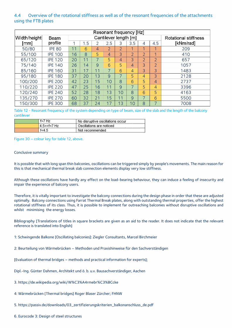
4.4 Overview of the rotational stiffness as well as of the resonant frequencies of the attachments using the FTB plates
Table 12 - Resonant frequency of the system depending on type of beam, size of the slab and the length of the balcony cantilever
Figure 30 – colour key for table 12, above.
Conclusive summary
It is possible that with long span thin balconies, oscillations can be triggered simply by people’s movements. The main reason for this is that mechanical thermal break slab connection elements display very low stiffness.
Although these oscillations have hardly any effect on the load-bearing behaviour, they can induce a feeling of insecurity and impair the experience of balcony users.
Therefore, it is vitally important to investigate the balcony connections during the design phase in order that these are adjusted optimally. Balcony connections using Farrat Thermal Break plates, along with outstanding thermal properties, offer the highest rotational stiffness of its class. Thus, it is possible to implement far outreaching balconies without disruptive oscillations and whilst minimising the energy losses.
Bibliography [Translations of titles in square brackets are given as an aid to the reader. It does not indicate that the relevant reference is translated into English]
1: Schwingende Balkone [Oscillating balconies]: Ziegler Consultants, Marcel Birchmeier
2: Beurteilung von Wärmebrücken – Methoden und Praxishinweise für den Sachverständigen
[Evaluation of thermal bridges – methods and practical information for experts];
Dipl.-Ing. Günter Dahmen, Architekt und ö. b. u.v. Bausachverständiger, Aachen
3. https://de.wikipedia.org/wiki/W%C3%A4rmebr%C3%BCcke
4: Wärmebrücken [Thermal bridges] Roger Blaser Zürcher; FHNW
5. https://passiv.de/downloads/03_zertifizierungskriterien_balkonanschluss_de.pdf
6. Eurocode 3: Design of steel structures
References
Anderson, B. (2006). Conventions for U-value calculations BR 443. Retrieved from https://www.brebookshop.com/archive/index.jsp.
BSI. (2017a). Building components and building elements-Thermal resistance and thermal transmittance-Calculation methods BSI Standards Publication. BS EN ISO 6946:2017.
BSI. (2017b). Thermal bridges in building construction-Heat flows and surface temperatures-Detailed calculations BSI Standards Publication. BS EN ISO 10211:2017.
BSI. (2017c). Thermal bridges in building construction-Linear thermal transmittance-Simplified methods and default values BSI Standards Publication. BS EN ISO 14683:2017.
Energy Saving Trust. (2008). Enhanced Construction Details : introduction and use Contents.
HM Government. (2007). Accredited Construction Details. Retrieved from www.energysavingtrust.org.uk/housing
NBS. (2018). Part L of the Building Regulations. Retrieved December 18, 2018, from https://www.isurv.com/info/35/part_l_of_the_building_regulations
Ward, T. (2006). IP 1/06. Retrieved from http://www.ihsti.com/tempimg/2FAE5FE-CIS888614800277903.pdf
Ward, T., & Sanders, C. (2007). Conventions for calculating linear thermal transmittance and temperature factors.
Farrat Isolevel Ltd Balmoral Road, Altrincham, Cheshire, WA15 8HJ, England, UKT. +44 (0) 161 924 1600 F. +44 (0) 161 924 1616 E. [email protected] www.farrat.com
Note: Although care has been taken to ensure that all the information contained herein is accurate, Farrat Isolevel Ltd assumes no responsibility for any errors or misinterpretations or any losses or damage arising therefrom.
About Farrat
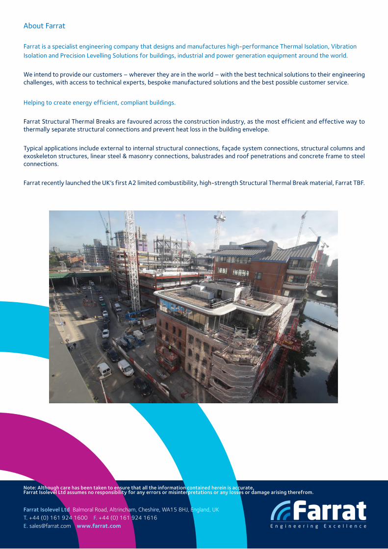
Farrat is a specialist engineering company that designs and manufactures high-performance Thermal Isolation, Vibration Isolation and Precision Levelling Solutions for buildings, industrial and power generation equipment around the world.
We intend to provide our customers – wherever they are in the world – with the best technical solutions to their engineering challenges, with access to technical experts, bespoke manufactured solutions and the best possible customer service.
Helping to create energy efficient, compliant buildings.
Farrat Structural Thermal Breaks are favoured across the construction industry, as the most efficient and effective way to thermally separate structural connections and prevent heat loss in the building envelope.
Typical applications include external to internal structural connections, façade system connections, structural columns and exoskeleton structures, linear steel & masonry connections, balustrades and roof penetrations and concrete frame to steel connections.
Farrat recently launched the UK’s first A2 limited combustibility, high-strength Structural Thermal Break material, Farrat TBF.