Embed Size (px)
Citation preview
Prologue This White Paper contains an elaboration of the discussion from the article, A Flawed and Dangerous U.S. Missile Defense Plan, which was published in May 2010 in Arms Control Today. It is intended for non-specialists who wish to have a more detailed understanding of the fundamental problems associated with the SM-3 and GMD systems discussed in the Arms Control Today article.
Summary of the issues Discussed in this White Paper Both the GMD and SM-3 systems are highly susceptible to massive confusion that leads to complete performance breakdowns when they encounter objects that have characteristics that are unexpected. These unexpected characteristics could include warheads that look different from what is expected, and/or objects that look somewhat like warheads. Even when it was known that false signals could be created by fragments from a chuffing rocket motor, the failure to prepare for it led to the catastrophic failure of the FTG-06 scene recognition program. This unintentional countermeasure that caused the failure of the FTG-06 can be easily replicated in combat by intelligent and resourceful adversaries, and requires technology that is far less complex than the technology needed to build and operate ballistic missiles.
Infrared and radar data from MIT Lincoln Laboratory, a Department of Defense Federally Funded Research and Development Center (FFRDC), shows that it will not be difficult for adversaries to create objects that will confront the scene matching process with targets that can easily be mistaken for warheads. The same MIT Lincoln Laboratory data shows that the SM-3 Block IA kill vehicle, which cannot measure the temperature of objects it observes, will be entirely inadequate if it encounters objects that are small and hot that produce infrared intensities comparable to those from warheads.
Department of Defense data from SM-3 intercept tests shows that kill vehicles can be easily made to miss warhead targets by simply attaching the warheads to pieces of upper rocket stage or by adding inflated appendages to make it impossible for the kill vehicle to know where to maneuver for a direct hit on a warhead.
The Missile Defense Agency found out in mid 1997 and early 1998, when it conducted the IFT-1A and IFT-2 experiments, that the GMD system could not tell the difference between simple balloons that had a diameter of 0.6 meters or cone-shaped objects that were roughly the size and temperature of a mock warhead. In response, the Missile Defense Agency lied to the Congress about the success of the IFT-1A and IFT-2 and cancelled all subsequent flight tests that were scheduled to use the credible decoys. Today, more than ten years after making false claims about the IFT-1A and IFT-2, the Missile Defense Agency has still not conducted a single missile defense flight test that proves the GMD can tell the difference between a mock warhead and the credible decoys flown in the IFT-1A and IFT-2.
The Department of Defense is still using the same people who have a record of turning a blind eye to fraud and of lying to Congress about missile defense capabilities. These individuals have a vested interest to not reveal information that would highlight their past transgressions. If the Congress and the Executive branch continue to ignore this situation, the nation can expect the past history of lying about missile defense performance capabilities to continue unabated into the future.
A Technically Detailed Description of Flaws in the SM-3 and GMD Missile Defense Systems
Revealed by the Defense Department’s Ballistic Missile Test Data By George N. Lewis and Theodore A. Postol
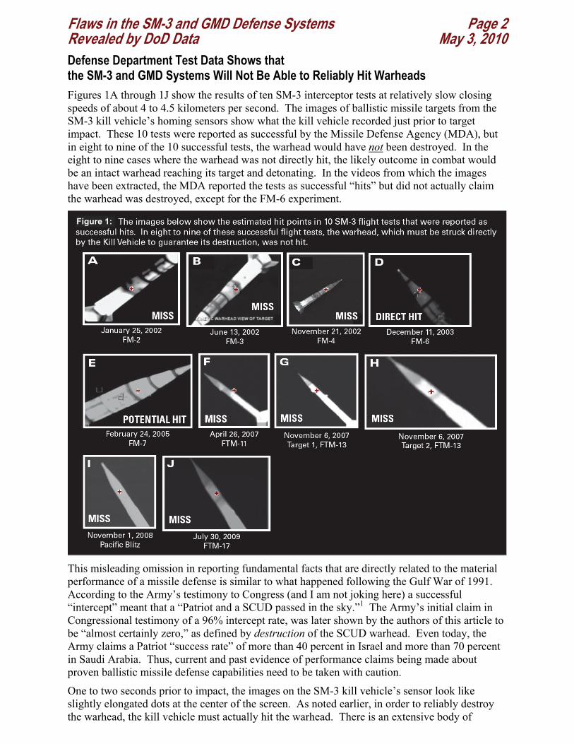
Flaws in the SM-3 and GMD Defense Systems Page 2 Revealed by DoD Data May 3, 2010 Defense Department Test Data Shows that the SM-3 and GMD Systems Will Not Be Able to Reliably Hit Warheads Figures 1A through 1J show the results of ten SM-3 interceptor tests at relatively slow closing speeds of about 4 to 4.5 kilometers per second. The images of ballistic missile targets from the SM-3 kill vehicle’s homing sensors show what the kill vehicle recorded just prior to target impact. These 10 tests were reported as successful by the Missile Defense Agency (MDA), but in eight to nine of the 10 successful tests, the warhead would have not been destroyed. In the eight to nine cases where the warhead was not directly hit, the likely outcome in combat would be an intact warhead reaching its target and detonating. In the videos from which the images have been extracted, the MDA reported the tests as successful “hits” but did not actually claim the warhead was destroyed, except for the FM-6 experiment.
This misleading omission in reporting fundamental facts that are directly related to the material performance of a missile defense is similar to what happened following the Gulf War of 1991. According to the Army’s testimony to Congress (and I am not joking here) a successful “intercept” meant that a “Patriot and a SCUD passed in the sky.”1 The Army’s initial claim in Congressional testimony of a 96% intercept rate, was later shown by the authors of this article to be “almost certainly zero,” as defined by destruction of the SCUD warhead. Even today, the Army claims a Patriot “success rate” of more than 40 percent in Israel and more than 70 percent in Saudi Arabia. Thus, current and past evidence of performance claims being made about proven ballistic missile defense capabilities need to be taken with caution.
One to two seconds prior to impact, the images on the SM-3 kill vehicle’s sensor look like slightly elongated dots at the center of the screen. As noted earlier, in order to reliably destroy the warhead, the kill vehicle must actually hit the warhead. There is an extensive body of
Figure 1:
Flaws in the SM-3 and GMD Defense Systems Page 3 Revealed by DoD Data May 3, 2010 animations, testimony to Congress, and MDA briefings that verify that the MDA recognizes that warheads must be directly hit to guarantee that they will be destroyed. If the kill vehicle instead hits the body of the rocket, it will tend to shatter and pass through the rocket body much like a bullet hitting a thin-walled drinking glass or an empty soda can, leaving the warhead undamaged and still falling towards its target. During the Persian Gulf War of 1991, we found only two engagements where there was clear evidence that a Patriot interceptor actually hit a SCUD ballistic missile, and in both cases the SCUD warhead was observed going on to the ground and detonating. These two engagements showed that even when Patriots actually hit the airframe of SCUDs (all other times, except for these two cases, Patriots completely missed the SCUDs) they destroyed the SCUD airframes, but failed to destroy the warheads, which then went on to the ground and exploded.
In order to find the location of the warhead that must be hit, the kill vehicle’s on-board computer analyzes video images from the interceptor’s infrared sensor as it hurtles towards the volume of space where the threat might be located. Initially, the image of a missile target in the threat volume is no more than a shapeless point of light. If there are other objects in the threat volume, the sensor will also see them as shapeless points of light. Since the interceptor’s ability to maneuver is limited, it must select which point of light to home in on well before it can see any details of a target’s shape.
By the time the sensors image contains information about the shape of different targets, there is only one to two seconds to maneuver. In this very short remaining time, the kill vehicle can only shift its hit point by no more than tens of meters. In the case of the artificially constrained experiments shown in figures 1A to 1J, this is a relatively easy task.
The flight test data in figures 1A to 1J show many striking artificialities that would not be present in actual combat conditions.
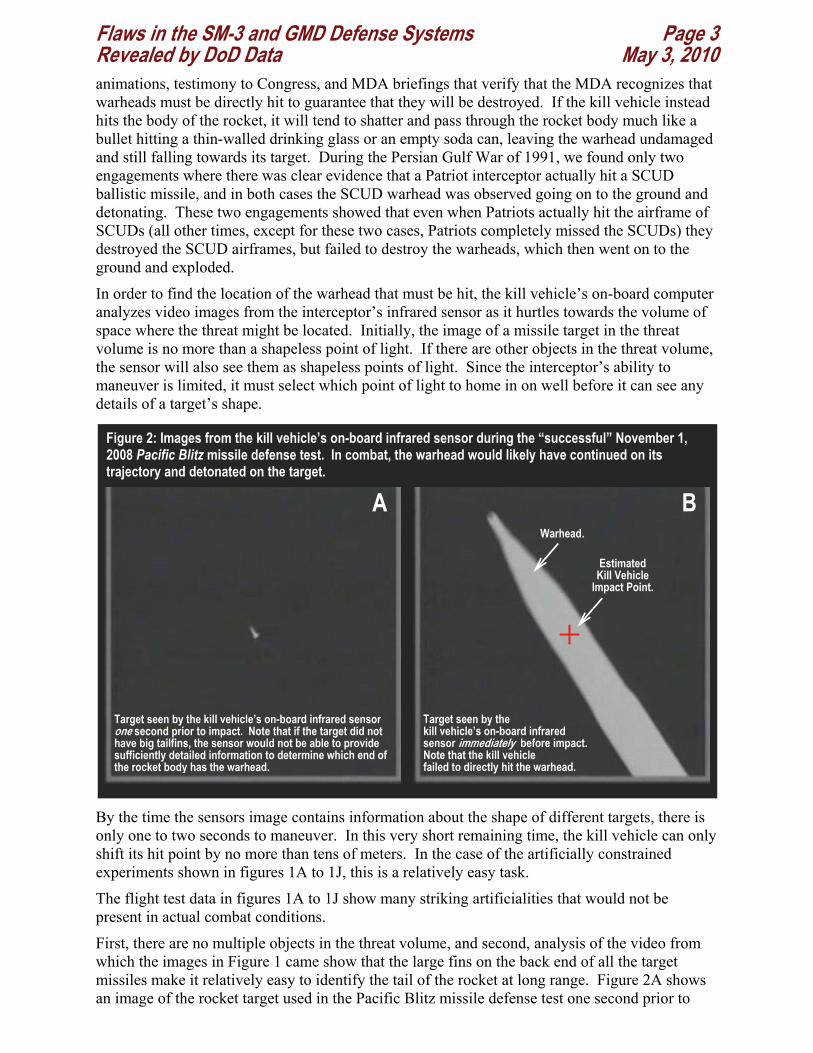
First, there are no multiple objects in the threat volume, and second, analysis of the video from which the images in Figure 1 came show that the large fins on the back end of all the target missiles make it relatively easy to identify the tail of the rocket at long range. Figure 2A shows an image of the rocket target used in the Pacific Blitz missile defense test one second prior to
Figure 2: Images from the kill vehicle’s on-board infrared sensor during the “successful” November 1, 2008 Pacific Blitz missile defense test. In combat, the warhead would likely have continued on its trajectory and detonated on the target.
BA
Estimated Kill Vehicle
Impact Point.
Target seen by the kill vehicle’s on-board infrared sensor one second prior to impact. Note that if the target did not have big tailfins, the sensor would not be able to provide sufficiently detailed information to determine which end of the rocket body has the warhead.
Target seen by the kill vehicle’s on-board infrared sensor immediately before impact. Note that the kill vehicle failed to directly hit the warhead.
Warhead.
Flaws in the SM-3 and GMD Defense Systems Page 4 Revealed by DoD Data May 3, 2010 target impact. As can be seen from the image, if the rocket target did not have tail fins, it would not be possible at such an early stage in the homing process (one to two seconds from impact) to identify which end of the rocket has the warhead.
Also adding to the artificialities in the tests, the target missiles are always side-on to the interceptor, making identification of the aim point much easier than would be the case if the missile were tumbling end over end, or nose-on and tail-on, relative to the interceptor as it approached. The exact geometry of the target missile is also known, so information about the location of the warhead relative to the tail section can be used to help determine the exact location of the warhead relative to the other end of the missile. Yet in spite of the highly choreographed nature of these tests, the Defense Department’s own data show that eight to nine times out of 10 the interceptors would not have hit the warhead, and therefore would not have destroyed it.
These test data show potential adversaries such as North Korea and Iran exactly how to go about defeating the SM-3 and GMD interceptors with technologies they already have flight tested. It also shows that the Department of Defense’s own technical oversight and assessment of the missile defense program, as described by the BMDR, is deeply flawed and unreliable, and is yet another example of why measures need to be taken to provide a truly independent source for the Executive and the Congress to confirm the veracity of claims being made by the Department of Defense and the Missile Defense Agency about missile defense performance.
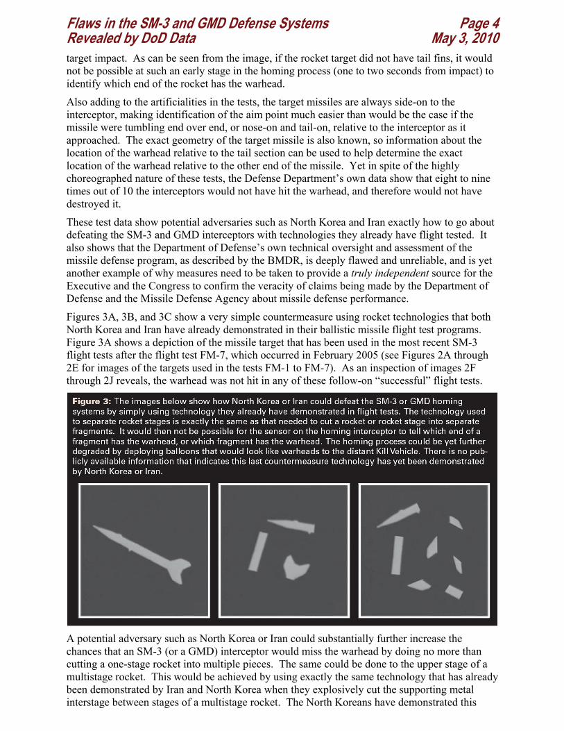
Figures 3A, 3B, and 3C show a very simple countermeasure using rocket technologies that both North Korea and Iran have already demonstrated in their ballistic missile flight test programs. Figure 3A shows a depiction of the missile target that has been used in the most recent SM-3 flight tests after the flight test FM-7, which occurred in February 2005 (see Figures 2A through 2E for images of the targets used in the tests FM-1 to FM-7). As an inspection of images 2F through 2J reveals, the warhead was not hit in any of these follow-on “successful” flight tests.
A potential adversary such as North Korea or Iran could substantially further increase the chances that an SM-3 (or a GMD) interceptor would miss the warhead by doing no more than cutting a one-stage rocket into multiple pieces. The same could be done to the upper stage of a multistage rocket. This would be achieved by using exactly the same technology that has already been demonstrated by Iran and North Korea when they explosively cut the supporting metal interstage between stages of a multistage rocket. The North Koreans have demonstrated this
Flaws in the SM-3 and GMD Defense Systems Page 5 Revealed by DoD Data May 3, 2010 technology in successful stage separations during the launch of the Taepodong 1 in 1998, and during the launch of the Unha-2 in 2009. The Iranians demonstrated this in February 2009, when they launched the Ohmid satellite on the Safir space-launch vehicle and in March of 2009 when they tested the two-stage Sajjil solid propellant ballistic missile.
The images shown in Figure 3 understate the complexity of the scene that would have to be analyzed by the homing kill vehicle, as the images were generated by assuming that the fragments only tumble in the plane perpendicular to the line of sight of the approaching interceptor. It also does not assume that additional false targets have been created by balloons or unfolded objects that might also be deployed as part of this countermeasure.
In the case of the GMD system, which is designed to be able to hit ICBM targets, the problem is essentially the same. Because the sensor must work at long range, there is also little time during the homing process to analyze complexes of multiple targets that could be intentionally, and easily, created by adversaries. In these situations, the closing speeds will be much higher than those encountered in SM-3 tests, about 12 to 15 kilometers per second compared to 4 to 4.5 kilometers per second. The higher speed requires that the kill vehicle see its targets at much longer range, 450 to 600 kilometers. In order to provide adequate time to maneuver to hit the target, the kill vehicle must have a much larger optical aperture to collect signals from the more distant targets, and a much narrower field of view (about 1 degree instead of the roughly 3.5 degrees used in the SM-3 kill vehicle) to be able to get comparably accurate spatial information. In other words, the vulnerabilities of the SM-3 and GMD kill vehicles to countermeasure technologies that have already been demonstrated by Iran and North Korea are the same.
Defense Department Data from the January 31, 2010 GMD Test Shows that the SM-3 and GMD Systems Will Not Be Able to Reliably Find Warheads Among Decoys The January 31, 2010 GMD missile defense flight test, the FTG-06, demonstrated how easy it would be for an adversary to confuse the GMD system. The source of the fundamental system vulnerability demonstrated in the flight test is the same as that revealed in the SM-3 flight test data discussed above – the fundamental inability of ground-based long-range radars and interceptor-based infrared homing sensors to provide images that allow for the unambigous identification of targets. Without such true and unambiguous image data, it is fundamentally not possible to recognize the warhead when it is attached to or surrounded by unexpected objects that also individually appear to be different from what was expected.
On April 6, 2010, Aviation Week reported2 that the Sea Based X-band radar (SBX) being used in the FTG-06 flight test failed to identify the warhead because it encountered “an unfamiliar threat scene.” To understand how revealing this failure is, it is first necessary to understand how the GMD system, or any other high-altitude hit-to-kill ballistic missile defense system, would identify the warhead from other objects that might travel along with it in the near vacuum of space.
The Threat Scene is simply the set of objects observed by a distant sensor. In the case of an ICBM, it might include a nose cone, a warhead, the upper rocket stage or pieces of the upper rocket stage that were created by an adversary who intentionally cut the stage into pieces, balloons that are spherical, or shaped like warheads, and the like.
No matter what sensor is being used, radar or infrared, if the missile defense system knows exactly how the warhead appears to the sensor then it can potentially identify a warhead among many other objects. This, of course, is only possible if the appearance of the warhead is exactly known, and of equal importance, it looks distinctly different from the other objects.
Flaws in the SM-3 and GMD Defense Systems Page 6 Revealed by DoD Data May 3, 2010 If the other objects look like, or nearly look like the warhead, or if the warhead looks different from what is expected, or is made to look different from what is expected, the warhead can only be selected as a target by pure chance. Even if the warhead is by chance correctly selected, hitting it may be problematic if it is attached to something, or enclosed in something, that makes it not possible for the kill vehicle to determine where it must arrive to directly hit the warhead.
In the case of the FTG-06, the solid propellant upper rocket stage, which deploys the warhead, and possibly other objects, exhibited an unexpected phenomenon known as chuffing. When a solid rocket motor burns out, sections of the remaining fuel in the spent rocket stage can spontaneously combust, causing tens or hundreds of mini-explosions per second in the shut down motor. This phenomenon can cause chunks of unburned fuel, insulator material, and the like to be expelled from the shut down rocket. The chunks of expelled rocket motor pieces have dimensions of less than one inch to 6 to 8 inches or more. From the point of view of the motor’s mission, to accelerate a payload to a given velocity and altitude, this is an inconsequential phenomenon.
In the FTG-06, the chuffing rocket motor expelled chunks of material that created numerous radar signals comparable in magnitude to the radar signal from a warhead. The radar signal therefore contained numerous unexpected targets. This “scene data” was passed to computers that were programmed to look for a scene that was expected. Since the scene was totally unexpected, the computer analysis failed catastrophically, resulting in a failure to identify the warhead, and possibly even a failure to properly track the entire complex of targets.
This failure reveals the fundamental vulnerability to catastrophic failure of the GMD and all similar such systems, which we have been writing about for more than a decade.3 The adversary can easily or inadvertently change the scene and target appearance using simple measures, like cutting the upper stage into pieces. The adversary can also change the appearance of the warhead by covering it with radar absorbing materials, or surrounding it with a balloon, or by yet other methods, with totally devastating consequences for the defense.
This same problem was discovered by the Missile Defense Agency more than ten years ago, during the first two flight tests known as the IFT-1A and IFT-2, flown in June 1997 and January 1998. The tests revealed that certain decoys looked enough like the warhead to make it impossible to reliably identify it. In response, the Missile Defense Agency concealed the problem and removed all the decoys that were identified as effective from all subsequent missile flight tests.4 Now, more than ten years later, the same fundamental flaw in the GMD is again revealed, in this case by a chuffing solid rocket motor. It is also worthy of note that the Missile Defense Agency has, now more than ten years later, still not conducted a single GMD intercept flight test against the same combination of warhead and decoys used in the IFT-1A and IFT-2.
Since the pieces of rocket motor from chuffing are small relative the length of the warhead, the failure of the X-band radar to provide data that could have been used for “scene recognition” can be solved by simply rejecting the X-band radar signals from small objects. This “filtering process” would have removed all the false target clutter from chuffing, and possibly would have simplified the resulting scene sufficiently to make it possible to identify the different objects being flown, all of which have been selected to look different from each other and all of which have an appearance that is well known to the radar engineers. This filtering process would, of course, not work if the objects were intentionally created by an adversary to have the same length as the warhead, or if the warhead were made to appear different from what is expected.
In another part of the FTG-06 experiment, it appears that a filtering process involving the kill vehicle’s infrared sensor worked. According to the Aviation Week article, the kill vehicle observed the target complex and picked out the warhead. This is not surprising, since the chuffing debris is physically small and is quite hot relative to the warhead. The infrared sensor on the kill vehicle is designed to recognize that small hot objects have different infrared signals
Flaws in the SM-3 and GMD Defense Systems Page 7 Revealed by DoD Data May 3, 2010 relative to the larger colder warhead and other debris. However, this fact does not mean the kill vehicle could not be defeated, as it is known from the IFT-1A and IFT-2 experiments that even a balloon of 1.5 to 2 feet in diameter would look like the warhead to the kill vehicle.
How Defense Department Data from MIT Lincoln Laboratory Shows How a Chuffing Rocket Motor Led to the Failure of the January 31, 2010 GMD Test, the FTG-06 MIT Lincoln Laboratory is the premiere laboratory for ballistic missile defense research in the United States. It is also a Federally Funded Research and Development Center (FFRDC), created by the US Congress to provide the US Government with high-quality scientific information on matters related to its expertise – which in this case is ballistic missile defense technology. Because of Lincoln Laboratory’s status as an FFRDC, it is granted access to all data needed by the US government for assessments of missile defense technology, including proprietary information that is developed by contractors who are in competition within the missile defense program.
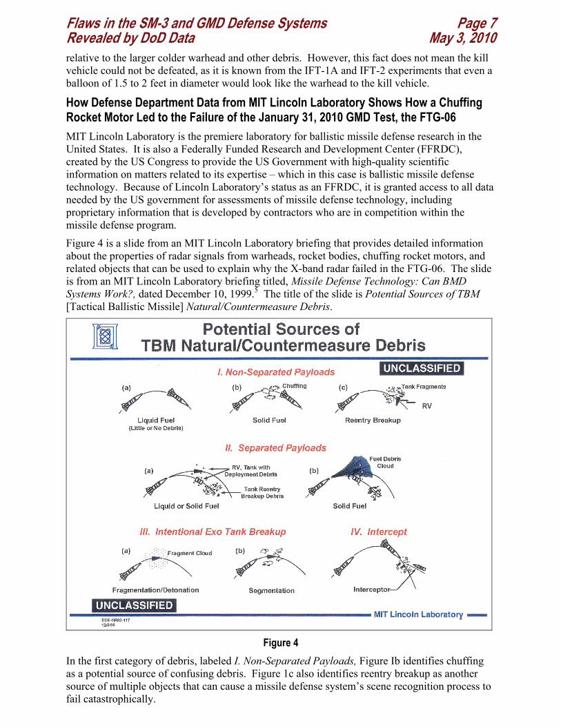
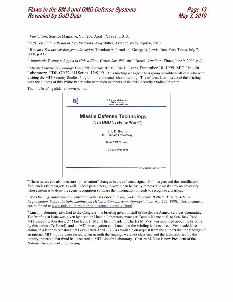
Figure 4 is a slide from an MIT Lincoln Laboratory briefing that provides detailed information about the properties of radar signals from warheads, rocket bodies, chuffing rocket motors, and related objects that can be used to explain why the X-band radar failed in the FTG-06. The slide is from an MIT Lincoln Laboratory briefing titled, Missile Defense Technology: Can BMD Systems Work?, dated December 10, 1999.5 The title of the slide is Potential Sources of TBM [Tactical Ballistic Missile] Natural/Countermeasure Debris.
Figure 4
In the first category of debris, labeled I. Non-Separated Payloads, Figure Ib identifies chuffing as a potential source of confusing debris. Figure 1c also identifies reentry breakup as another source of multiple objects that can cause a missile defense system’s scene recognition process to fail catastrophically.
Flaws in the SM-3 and GMD Defense Systems Page 8 Revealed by DoD Data May 3, 2010 In the third category of debris in figure 4, labeled III. Intentional Exo-Tank Breakup, Figure IIIb identifies “segmentation” of the upper stage of a ballistic missile as a potential countermeasure. This is the inadvertent and unexpected countermeasure that led to the failure of the X-band radar in the FTG06 GMD experiment of January 31, 2009. As shown in Figure 4, even though the phenomenon of chuffing was well known and studied, its unexpected appearance during the FTG-06 caused the collapse of the X-band radar’s scene recognition software. This “accident” in the FTG-06 experiment should be a warning about the fragility and susceptibility of the scene recognition process to both inadvertent and intended countermeasures.
During the Gulf War of 1991, the inadvertent breakup of Al-Husain SCUDs while Patriot interceptors were attempting to home in on previously intact SCUDs completely disrupted Patriot missile defense intercept attempts. In some cases, the confusion created by the breakups of SCUDs was so severe that it caused Patriots to dive to the ground, causing a significant increase in ground-damage in target areas the Patriots were supposed to defend.
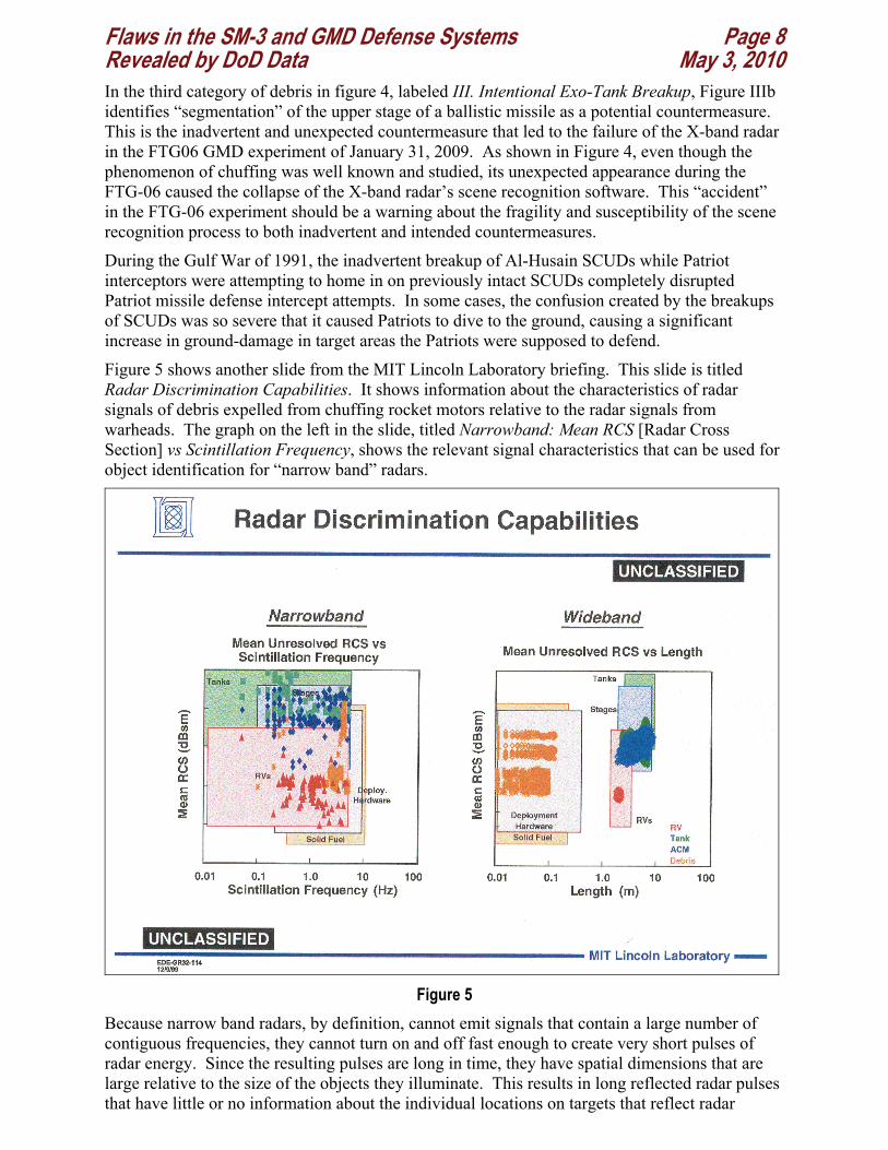
Figure 5 shows another slide from the MIT Lincoln Laboratory briefing. This slide is titled Radar Discrimination Capabilities. It shows information about the characteristics of radar signals of debris expelled from chuffing rocket motors relative to the radar signals from warheads. The graph on the left in the slide, titled Narrowband: Mean RCS [Radar Cross Section] vs Scintillation Frequency, shows the relevant signal characteristics that can be used for object identification for “narrow band” radars.
Figure 5
Because narrow band radars, by definition, cannot emit signals that contain a large number of contiguous frequencies, they cannot turn on and off fast enough to create very short pulses of radar energy. Since the resulting pulses are long in time, they have spatial dimensions that are large relative to the size of the objects they illuminate. This results in long reflected radar pulses that have little or no information about the individual locations on targets that reflect radar
Flaws in the SM-3 and GMD Defense Systems Page 9 Revealed by DoD Data May 3, 2010 signal. This inability to observe the distinct reflection locations on targets makes it impossible to measure the lengths or other details of the objects being illuminated.
Because of this limitation on narrowband radars, they can only reliably measure the strength of the radar reflection from distant objects and short-time fluctuations in the magnitude of the total signal. These short-time signal fluctuations, called scintillations, are due to the tumbling, wobbling, or other motions of the objects being observed.6 As an inspection of the MIT Lincoln Laboratory data shows, the radar signal from some fraction of the objects expelled from a chuffing rocket motor will look the same as those expected from warheads. The MIT Lincoln Laboratory slide shows many of the pieces of propellant generated by chuffing have radar signals as strong as those from warheads and scintillate at comparable frequencies to the signals from warheads. Thus, the warheads do not have a unique signal relative to a large fraction of the objects created by chuffing, and as a result, a chuffing rocket motor can create a confusion of possible targets that will make it difficult or impossible for a narrowband radar to identify warheads from the many other apparently similar objects.
The MIT Lincoln Laboratory slide also shows a graph on the right labeled Wideband: Mean Unresolved RCS [Radar Cross Section] vs Length. Wideband radars, like the Sea-Based X-band and Forward-Based X-band radars, are capable of producing very short pulses, which have dimensions that are small relative to the size of warheads. This makes it possible to see the distinct radar reflections from a warhead, which are typically from the rounded front-nose and the back end of a cone-shaped warhead. When it is possible for the radar to observe these reflections, the radar can measure the length of the warhead and other objects as well. The Sea-Based X-band and Forward-Based X-band radars can produce pulses that are short enough to measure the size of objects to a precision of 10 to 15 centimeters (0.10 to 0.15 meters).
In cases where the radar can measure the length of a cone-shaped warhead relative to the much smaller pieces of chuffing rocket motor, the signals from the smaller pieces of expelled motor debris can be removed (or “filtered” out) before radar data are passed to the scene recognition software. Of course, this filtering is only possible when the radar can measure the length of the warhead.
One way an adversary could make it impossible for the radar to measure the length of a warhead is to simply cover the warhead’s rounded nose with a thin metal cone-shaped sleeve that has a pointy nose. When this is done, the radar reflection from the rounded warhead nose simply disappears, and the only remaining reflection from the warhead will likely be from the aft end (there could also be a radar reflection from the window used for the warhead’s radar fuse, but this can also be covered, as the fuse window is only needed at low altitudes). The aft end reflection can also be reduced by rounding the back of the warhead or putting radar absorbing material round the aft end of the warhead. Photographs and diagrams of US Air Force warheads show that they all have rounded edges at the aft end. These two simple measures would deny the X-band radar the ability to measure the length of the warhead, or even, in many situations, the ability to detect it at all.
Also of importance is that the warhead radar signal must look like the signal that is expected from the warhead. When the characteristics of the radar signal from the warhead are different from what is expected, and the characteristics of the radar signal from the other objects surrounding the warhead are also unexpected, it is fundamentally not possible to determine which signals are from the warhead and which are from debris. Thus, the FTG-06 revealed only a small subset of the many possibilities that could guarantee a failure of the system.
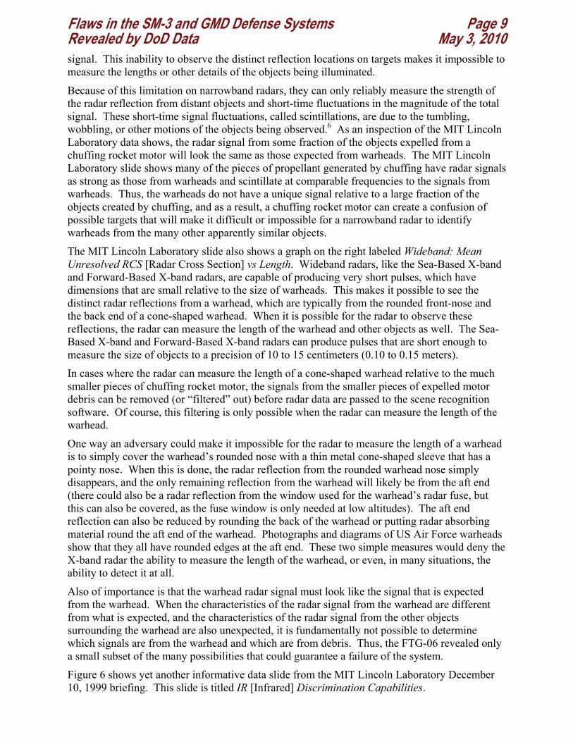
Figure 6 shows yet another informative data slide from the MIT Lincoln Laboratory December 10, 1999 briefing. This slide is titled IR [Infrared] Discrimination Capabilities.
Flaws in the SM-3 and GMD Defense Systems Page 10 Revealed by DoD Data May 3, 2010
Figure 6
The graph on the left of the slide in figure 6 shows infrared intensity versus scintillation frequency data for debris from a chuffing rocket motor. The graph also shows the same properties for warheads, upper rocket stages, and other objects that could be associated with the deployment of payloads from ballistic missiles.
As can be seen from the MIT Lincoln Laboratory data, fragments of debris from a chuffing rocket motor can have infrared intensities and scintillation frequencies similar to those of warheads. These data therefore show that the current SM-3 Block IA interceptor will not be able to tell the difference between small pieces of hot debris and warheads when it tries to home on warheads. Since it would only be able to determine that pieces of hot debris are small relative to the size of warheads two to three seconds before an impact, the kill vehicle would have no time to divert to the real target, even if it was able to recognize it in the last few seconds of homing.
This means that the SM-3 Block IA kill vehicle is even more unreliable and susceptible to catastrophic failures during the homing process than the GMD kill vehicle!
The graph on the right of the slide shown in figure 6 shows the discrimination capabilities of kill vehicles that measure the infrared signals of distant targets at two wavelengths. In this case, the infrared signal at two wavelengths can be used to estimate the temperature of the targets in addition to the intensity. Although many of the pieces of hot debris from a chuffing rocket motor have the same overall brightness as a warhead, they are not at the same temperature. Thus, a kill vehicle that measures the infrared signal at two wavelengths could determine that pieces of debris from the rocket motor that are as bright as the warhead are too hot to be the warhead.
The administration currently is planning to procure SM-3 Block IA kill vehicles that will not be able to tell the difference between hot rocket debris and warheads before it procures Block IB kill vehicles that will be able to determine that such debris are hot relative to warhead targets.
Flaws in the SM-3 and GMD Defense Systems Page 11 Revealed by DoD Data May 3, 2010 What the MDA Concealed After the IFT-1A and IFT-2 Missile Defense Experiments in June 1997 and January 1998 Reveals that is Relevant to the Failure of the January 2010 FTG-06 Missile Defense Experiment The fact that the GMD and later versions of the SM-3 kill vehicles are able to observe two infrared wavelengths and make rough measurements of the temperature of targets does not mean that the kill vehicles are difficult to counter.
In June of 1997 and January of 1998 the Missile Defense Agency ran two flight tests, the IFT-1A and the IFT-2. These two experiments were designed to determine whether a kill vehicle could identify multiple objects that had roughly the same dimensions and temperature of the warhead. The first of the two experiments, the IFT-1A, failed to take any usable data due to multiple engineering failures. These included a failure in the sensor cooling system, a failure in the sensor’s temperature measurement system, and a partial failure in the electrical system associated with the sensor. These multiple engineering failures, most importantly, the failure of the sensor to cool to its proper operating temperature, resulted in a total failure to take usable data on the targets.
The second experiment, the IFT-2, took data that confirmed that certain very simple decoys could not be discriminated from warheads. The particular decoys at issue were two balloons of 0.6 m diameter and two cone-shaped rigid decoys that were geometrically similar in size and shape relative to a mock warhead. Because these extremely simple decoys were at nearly the same temperature as the mock warhead, and they were also of similar size relative to the mock warhead, the infrared signals from the different objects were sufficiently similar that the warhead could not be discriminated from the decoys.
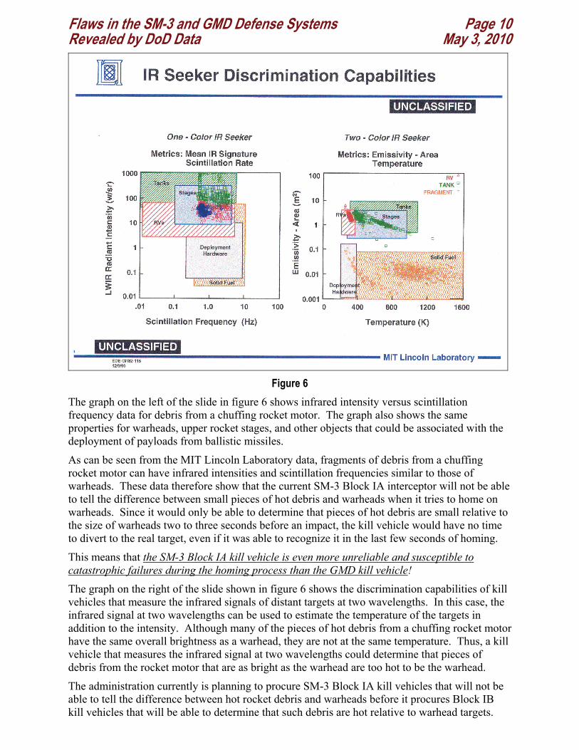
Following these experiments, the Missile Defense Agency removed all the decoys that it determined could defeat the missile defense from all follow-on experiments (see figure 7 below, from endnote 4).
Figure 7
Even now, after more than ten years, the Missile Defense Agency has still not flown any of these decoys in any of the GMD missile defense flight tests. In spite of this clear and unambiguous record of coverup, the Ballistic Missile defense review now claims that the record of missile defense flight tests demonstrates that the United States currently, and for the foreseeable future, has a working ballistic missile defense against ICBMs.
In spite of the total failure of the IFT-1A to take any usable data, and the failure of the IFT-2 to demonstrate that the kill vehicle could tell the difference between a warhead and very simple decoys, the then Director of the Missile Defense Agency, LTG Lester B. Lyles, told the Chair of the Senate Subcommittee on Defense of the Senate Appropriations Committee:7
Flaws in the SM-3 and GMD Defense Systems Page 12 Revealed by DoD Data May 3, 2010
During the past year, Mr. Chairman, we conducted two very successful NMD exoatmospheric kill vehicle - or EKV - flight tests. Two different industry teams supported those efforts and are competing against each other. We demonstrated in those initial tests that we can use an EKV sensor to identify and track objects in space - including threat representative targets and decoys - and allow us to discriminate and determine what is an actual target and what is not.
On july 6, 2009, General Lyles, was appointed as Vice Chairman of the Defense Science Board, the organization that will have direct oversight of the administration’s new missile defense program. Lyles was appointed to this position by Ashton B. Carter, the current Undersecretary of Defense for Acquisition, Technology and Logistics, who had direct technical oversight of the Ballistic Missile Defense Review. Carter was formerly on the oversight board of MIT Lincoln Laboratory when allegations were made that Lincoln Laboratory had fraudulently represented the IFT-1A and IFT-2 to federal investigators as successful experiments.8 Carter took no action to investigate the matter.
It should be no surprise that the Ballistic Missile Defense Review is so deeply flawed and misleading when those responsible for it have had such a startling record of turning a blind eye towards fraud in the missile defense program and of support for individuals who have lied about missile defense to the Congress.
Flaws in the SM-3 and GMD Defense Systems Page 13 Revealed by DoD Data May 3, 2010
1 Patriotisms, Science Magazine, Vol. 256, April 17, 1992, p. 313. 2 GBI Test Failure Result of Two Problems, Amy Butler, Aviation Week, April 6, 2010 3 We can’t Tell the Missiles from the Mylar, Theodore A. Postol and George N. Lewis, New York Times, July 7, 2000, p A19. 4 Antimissile Testing is Rigged to Hide a Flaw, Critics Say, William J. Broad, New York Times, June 9, 2000, p A1. 5 Missile Defense Technology: Can BMD Systems Work?, Eric D. Evans, December 10, 1999, MIT Lincoln Laboratory, EDE-GR32-111Series, 12/9/99. This briefing was given to a group of military officers who were visiting the MIT Security Studies Program for command school training. The officers later discussed the briefing with the authors of this White Paper, who were then members of the MIT Security Studies Program.
The title briefing slide is shown below.
6 These radars can also measure “polarization” changes in the reflected signals from targets and the scintillation frequencies from targets as well. These parameters, however, can be easily removed or masked by an adversary whose intent is to deny the scene recognition software the information it needs to recognize a warhead. 7 See Opening Statement By Lieutenant General Lester L. Lyles, USAF, Director, Ballistic Missile Defense Organization, before the Subcommittee on Defense, Committee on Appropriations, April 22, 1998. This document can be found at www.mda.mil/news/public_statements_archive.html. 8 Lincoln laboratory also lied to the Congress in a briefing given to staff of the Senate Armed Services Committee. The briefing at issue was given by a senior Lincoln Laboratory manager, Dennis Keane et al, to Sen. Jack Reed, MIT Lincoln Laboratory, 27 March 2001. MIT’s then President, Charles M. Vest was informed about the briefing by this author (Te Postol), and an MIT investigation confirmed that the briefing had occurred. Vest made false claims in a letter to Senator Carl Levin dated April 1, 2004 (available on request from the author) that the findings of an internal MIT inquiry were secret, when in truth the findings were not classified and the facts reported by the inquiry indicated that fraud had occurred at MIT Lincoln Laboratory. Charles M. Vest is now President of the National Academy of Engineering.