Embed Size (px)
Citation preview

A TEST OF AUTOMATIC BUILDING CHANGE DETECTION APPROACHES
Nicolas Championa, Franz Rottensteinerb, Leena Matikainenc, Xinlian Liangc, Juha Hyyppäc and Brian P. Olsend
a IGN, MATIS, Saint-Mandé, France – [email protected]
b Institute of Photogrammetry and GeoInformation, Leibniz Universität Hannover, Germany – [email protected]
c FGI, Dept. of Remote Sensing and Photogrammetry, Masala, Finland – {L eena.Matikainen, Xinlian.Liang, Juha.Hyyppa}@fgi.fi
d National Survey and Cadastre (KMS), Copenhagen, Denmark – [email protected]
Commission III, WG III/4
KEY WORDS: Change Detection, Building, 2D Vector Databases, Algorithms Comparison, Quality Assessment ABSTRACT: The update of databases – in particular 2D building databases – has become a topical issue, especially in the developed countries where such databases have been completed during the last decade. The main issue here concerns the long and costly change detection step, which might be automated by using recently acquired sensor data. The current deficits in automation and the lack of expertise in the domain have driven the EuroSDR to launch a test comparing different change detection approaches, representative of the current state-of-the-art. The main goal of this paper is to present the test bed of this comparison and the results that have been obtained for three different contexts (aerial imagery, satellite imagery, and LIDAR). In addition, we give the overall findings that emerged from our experiences and some promising directions to follow for building an optimal operative system in the future.
1. INTRODUCTION
The production of 2D topographic databases has been completed in many industrialised countries. Presently, most efforts in the National Mapping and Cadastral Agencies (NMCAs) are devoted to the update of such databases. As the update process is generally carried out manually by visual inspection of orthophotos, it is time-consuming and expensive. As a consequence, its automation is of high practical interest for the NMCAs. The update procedure can be split into two steps: change detection, in which the outdated database is compared to recently collected sensor data in order to detect changes, and vectorization, i.e. the digitization of the correct geometry of the changed objects. Given the state-of-the-art in automatic object detection (Mayer, 2008), only the automation of the change detection step seems to be possible at this time. The key idea is to focus the operator’s attention on the areas that may have changed. Work is saved because the operator needs not inspect areas classified as unchanged by the automatic procedure. The current deficits in automation and the lack of expertise within the NMCAs have driven the EuroSDR (European Spatial Data Research - http://www.eurosdr.net) to lauch a project about change detection. It also aims at evaluating the feasibility of semi-automatically detecting changes in a 2D building vector database from optical imagery or LIDAR. Three subtopics are investigated in detail, firstly the impact of methodology; secondly, the impact of the type and spatial resolution of input data; lastly, the impact of the complexity of the scene in terms of interfering objects such as roads. The methodology consists in comparing four different algorithms representative for the current state-of-the-art in the field of change detection. First results, achieved for the cases where only aerial and satellite images are used, were presented in (Champion et al., 2008). The results obtained there showed the limitations of change detection methods, especially in relation to the quality of input
data. The main goal of this paper is to present the final results of the project, including a LIDAR dataset, and to give a detailed evaluation of the outcomes delivered by the approaches compared here. After describing the datasets and the evaluation procedure (Section 2), the methods compared in the test are concisely introduced (Section 3). In Section 4, a thorough evaluation is carried out, including an analysis of the performance of change detection with respect to the update status of the buildings and the building size. The weak and strong points are then identified both for the datasets and the methodologies, and they used to give overall findings and recommendations for building an optimal operative system for change detection in the future.
2. INPUT DATA AND TEST SET-UP
Three test areas are used for the comparison: Marseille (France), Toulouse (France), and Lyngby (Denmark). The area covered by the test sites is 0.9 x 0.4 km2 in Marseille, 1.1 x 1.1 km2 in Toulouse, and 2.0 x 2.0 km2 in Lingby. The test areas differ considerably regarding topography, land use, urban configuration and roofing material. The terrain is hilly in Marseille and Toulouse and relatively flat in Lyngby. Marseille features a densely built-up area consisting of small buildings of variable height, all connected to each other and mostly covered with red tile. Toulouse and Lyngby feature a suburban area, mostly composed of detached buildings and characterised by a large variety of roofing materials such as slate, gravel, or concrete. Colour Infrared (CIR) orthophotos and Digital Surface Model (DSMs) are available for all test areas. In Marseille and Toulouse an image matching algorithm (Pierrot-Deseilligny and Paparoditis, 2006) was used to derive the DSM from input images. In Marseille, these images are multiple aerial images having a forward and side overlap of 60%. The Ground
145
In: Stilla U, Rottensteiner F, Paparoditis N (Eds) CMRT09. IAPRS, Vol. XXXVIII, Part 3/W4 --- Paris, France, 3-4 September, 2009 ¯¯¯¯¯¯¯¯¯¯¯¯¯¯¯¯¯¯¯¯¯¯¯¯¯¯¯¯¯¯¯¯¯¯¯¯¯¯¯¯¯¯¯¯¯¯¯¯¯¯¯¯¯¯¯¯¯¯¯¯¯¯¯¯¯¯¯¯¯¯¯¯¯¯¯¯¯¯¯¯¯¯¯¯¯¯¯¯¯¯¯¯¯¯¯¯¯¯¯¯¯¯¯¯¯¯¯¯¯

Sample Distance (GSD) of all input data is 0.2 m. In Toulouse, these images are Pléiades tri-stereoscopic satellite images. The GSD of all input data is 0.5 m. Lastly, the DSM used in Lyngby was derived from first pulse LIDAR data, and the digital orthophoto was generated from a scanned aerial image, both with a GSD of 1 m. For the three test areas, up-to-date vector databases representing the 2D outlines of buildings were available. They served as a reference in the test. In order to achieve an objective evaluation, the outdated databases were simulated by manually adding or removing buildings Thus, 107 changes (out of 1300 buildings in the scene) were simulated in Marseille (89 new and 18 demolished buildings); 40 (out of 200) in Toulouse (23 new, 17 demolished) and 50 (out of 500) in Lyngby (29 new, 21 demolished). The outdated databases were converted to binary building masks having the same GSD as the input data and then distributed to the participants along with input data. Each group participating in the test was asked to deliver a change map in which each building of the vector database is labelled either as unchanged, demolished or new. Because the methods have been developed in different contexts, their designs noticeably differ, for instance regarding the definitions of the classes considered in the final change map – e.g. four classes for (Champion, 2007) and six classes for (Rottensteiner, 2008) – and the format of the input data – e.g. vector for (Champion, 2007) and raster for (Matikainen et al., 2007). As a work-around, it was decided to use the building label image representing the updated version of the building map (cf. Section 3) for the evaluation of those methods that do not deliver the required change map in the way described above. Only the method by (Champion, 2007) delivered such a change map, which was also directly used in the evaluation. In order to evaluate the results achieved by the four algorithms, they are compared to the reference database, and the completeness and the correctness of the results (Heipke et al., 1997) are derived as quality measures:
FPTP
TPsCorrectnes
FNTP
TPssCompletene
+=
+=
(1)
In Equation 1, TP, FP, and FN are the numbers of True Positives, False Positives, and False Negatives, respectively. They refer to the update status of the vector objects in the automatically-generated change map, compared to their real update status given by the reference. In the case where the final change map is directly used for the evaluation, i.e. with (Champion, 2007), a TP is an object of the database reported as changed (demolished or new) that is actually changed in the reference. A FP is an object reported as changed by the algorithm that has not changed in the reference. A FN is an object that was reported as unchanged by the algorithm, but is changed in the reference. In the three other cases, where a building label image representing the updated map is used for the evaluation, the rules for defining an entity as a TP, a FP, or a FN had to be adapted. In these cases, any unchanged building in the reference database is considered a TN if a predefined percentage (Th) of its area is covered with buildings in the new label image. Otherwise, it is considered a FP, because the absence of any correspondence in the new label image indicates a change. A demolished building in the reference database is considered a TP if the percentage of its area covered by any
building in the new label image is smaller than Th. Otherwise, it is considered to be a FN, because the fact that it corresponds to buildings in the new label image indicates that the change has remained undetected. A new building in the reference is considered a TP if the cover percentage is greater than Th. Otherwise, it is considered a FN. The remaining areas in the new label image that do not match any of the previous cases correspond to objects wrongly alerted as new by the algorithm and thus constitute FPs. The quality measures are presented in the evaluation on a per-building basis (rather than on a per-pixel basis), as the effectiveness of a change detection approach is limited by the number of changed buildings that is missed or over-detected and not by the area covered by these buildings. As explained in the Section 4, these quality measures are also computed separately for each change class.
3. CHANGE DETECTION APPROACHES
The four methods tested in this study are concisely presented, ordered alphabetically according to the corresponding author. Champion, 2007: The input of the method is given by a DSM, CIR orthophotos and the outdated vector database. Optionally, the original multiple images can also be used. The outcome of the method is a modified version of the input vector database, in which demolished and unchanged buildings are labelled and vector objects assumed to be new are created. The method starts with the verification of the database, where geometric primitives extracted from the DSM (2D contours, i.e. height discontinuities) and, optionally, from multiple images (3D segments), are collected for each object of the existing database and matched with primitives derived from it. A similarity score is then computed for each object and used to achieve a final decision about acceptance (unchanged) and rejection (changed or demolished). The second processing stage, i.e. the detection of new buildings, is based on a Digital Terrain Model (DTM) automatically derived from the DSM (Champion and Boldo, 2006), a normalised DSM (nDSM), defined as the difference between the DSM and the DTM, and an above-ground mask, processed from the nDSM by thresholding. Appropriate morphological tools are then used to compare this latter mask to the initial building mask derived from the vector database and a vegetation mask computed from CIR orthophotos and an image corresponding to the Normalised Difference Vegetation Index (NDVI), which results in the extraction of new buildings. Matikainen et al., 2007: The building detection method of the Finnish Geodetic Institute (FGI) was originally developed to use laser scanning data as primary data. In this study, it is directly applied to the input DSM and CIR orthophotos. A raster version of the database (for a part of the study area) is used for training. The method includes three main steps. It starts with segmentation and a two-step classification of input data into ground and above-ground, based on a point-based analyisis followed by an object-based analysis and using the Terrasolid1 and Definiens2 software systems. This is followed by the definition of training segments for buildings and trees and the classification of the above-ground segments into buildings and trees. This classification is based on predefined attributes and a classification tree (Breiman et al., 1984). A large number of
1 http://www.terrasolid.fi/. Last visited: 30 June 2009. 2 http://www.definiens.com/. Last visited: 30 June 2009.
146
CMRT09: Object Extraction for 3D City Models, Road Databases and Traffic Monitoring - Concepts, Algorithms, and Evaluation ¯¯¯¯¯¯¯¯¯¯¯¯¯¯¯¯¯¯¯¯¯¯¯¯¯¯¯¯¯¯¯¯¯¯¯¯¯¯¯¯¯¯¯¯¯¯¯¯¯¯¯¯¯¯¯¯¯¯¯¯¯¯¯¯¯¯¯¯¯¯¯¯¯¯¯¯¯¯¯¯¯¯¯¯¯¯¯¯¯¯¯¯¯¯¯¯¯¯¯¯¯¯¯¯¯¯¯¯¯
attributes can be used, e.g. mean values, standard deviations, texture and shape of the segments. The method automatically selects the most useful ones for classification. In the Marseille area, the criteria selected in the tree included only the NDVI. In the Lyngby area, NDVI and a shape attribute were selected. The third stage consists of a post-processing step that analyses the size and neighborhood of building segments and corrects their class accordingly. Building detection results in a building label image which is used for the comparison in our test. Olsen and Knudsen, 2005: The input of the method is given by a DSM, CIR orthophotos and a raster version of the outdated database. The method starts with the generation of a DTM, estimated from the DSM through appropriate morphological procedures, a nDSM and an Object Above Terrain (OAT) mask. This is followed by a two-step classification that aims at distinguishing building from no building objects. This classification is based on criteria that best characterise buildings (especially in terms of size and form) and results in the building label image that is used for the evaluation in this study. The last stage is the actual change detection step, in which the classification outcomes is compared to the initial database in order to extract a preliminary set of potential changes (on a per-pixel basis) that is then post-processed in order to keep only the objects that are assumed to have changed. Rottensteiner, 2008: This method requires a DSM as the minimum input. Additionally it can use an NDVI image, height differences between the first and the last laser pulse, and the existing database, available either in raster or vector format. The workflow of the method starts with the generation of a coarse DTM by hierarchical morphological filtering, which is used to obtain a nDSM. Along with the other input data, the nDSM is used in a Dempster-Shafer fusion process carried out on a per-pixel basis to distinguish four object classes: buildings, trees, grass land, and bare soil. Connected components of building pixels are then grouped to constitute initial building regions and a second Dempster-Shafer fusion process is performed on a per-region basis to eliminate remaining trees. Finally, there is the actual change detection step, in which the detected buildings are compared to the existing map, which produces a change map that describes the change status of buildings, both on a per-pixel and a per-building level. Additionally, a label image corresponding to the new state of the data base is generated. In spite of the thematic accuracy of the change map produced by this method, it was decided to use this building label image for the evaluation in this test.
4. EVALUATION AND DISCUSSION
In our opinion, the effectiveness of a change detection system is related to its capacity to guide the operator’s attention only to objects that have changed so that unchanged buildings do not need to be investigated unnecessarily. These considerations result in the evaluation criteria used in this paper to analyze the change detection performance. On the one hand, to support the generation of a map that is really up-to-date, i.e. to be effective qualitatively, the completeness of the system for buildings classified as demolished and the correctness for unchanged buildings are required to be high. The completeness of new buildings also has to be high if the operator is assumed not to look for any new building except for those which are suggested by the system. (Note that this also holds true for modified buildings, a case not considered in this study because the simulated changes only consisted in new and demolished
buildings). On the other hand, to reduce the amount of manual work required by the operator i.e. to be effective economically, the correctness of the changes highlighted by the system and the completeness of unchanged buildings must be high. However, if a low completeness of unchanged buildings implies that many buildings are checked uselessly, this is not necessarily critical for the application itself, because the updated database is still correct. Moreover, the economical efficiency that could then appear to be low has to be put into perspective according to the size of the building database to update. For instance, if a change detection system reports 60% of a national database as changed, we cannot necessarily conclude about the inefficiency of this system because it still means that 40% of the buildings need not be checked, which amounts to millions of buildings. 4.1 Overall Analysis
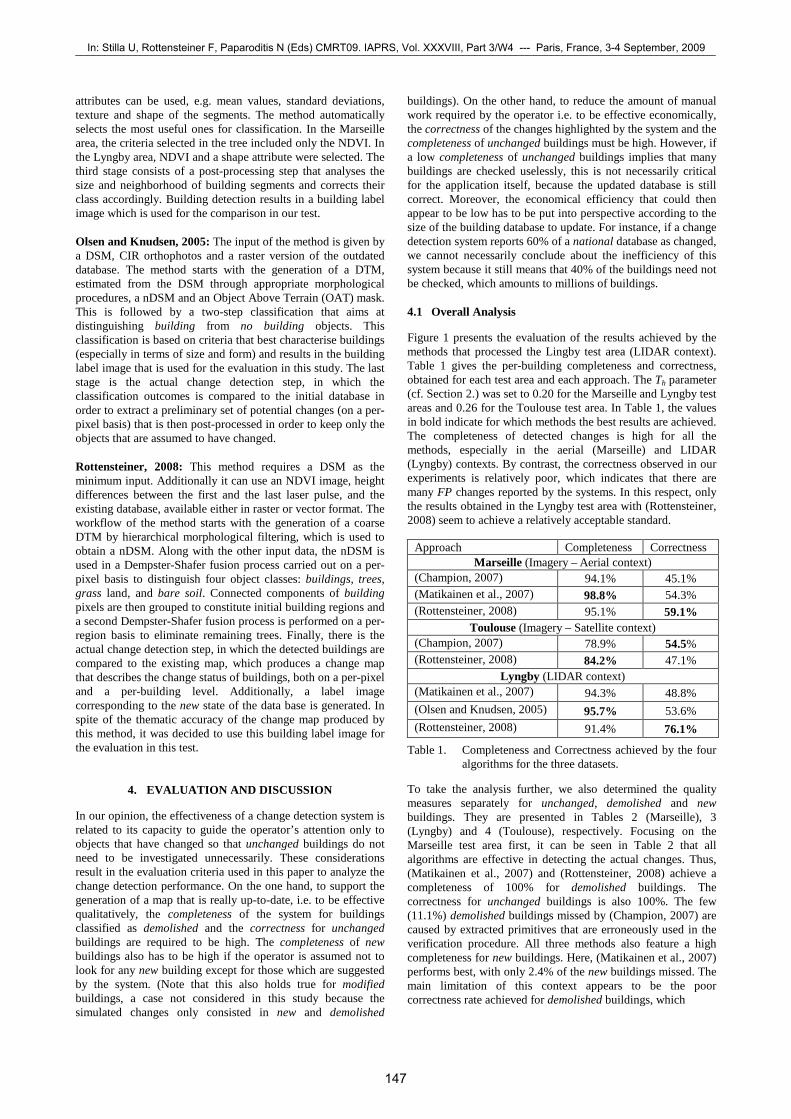
Figure 1 presents the evaluation of the results achieved by the methods that processed the Lingby test area (LIDAR context). Table 1 gives the per-building completeness and correctness, obtained for each test area and each approach. The Th parameter (cf. Section 2.) was set to 0.20 for the Marseille and Lyngby test areas and 0.26 for the Toulouse test area. In Table 1, the values in bold indicate for which methods the best results are achieved. The completeness of detected changes is high for all the methods, especially in the aerial (Marseille) and LIDAR (Lyngby) contexts. By contrast, the correctness observed in our experiments is relatively poor, which indicates that there are many FP changes reported by the systems. In this respect, only the results obtained in the Lyngby test area with (Rottensteiner, 2008) seem to achieve a relatively acceptable standard.
Approach Completeness Correctness Marseille (Imagery – Aerial context)
(Champion, 2007) 94.1% 45.1% (Matikainen et al., 2007) 98.8% 54.3% (Rottensteiner, 2008) 95.1% 59.1%
Toulouse (Imagery – Satellite context) (Champion, 2007) 78.9% 54.5% (Rottensteiner, 2008) 84.2% 47.1%
Lyngby (LIDAR context) (Matikainen et al., 2007) 94.3% 48.8% (Olsen and Knudsen, 2005) 95.7% 53.6% (Rottensteiner, 2008) 91.4% 76.1%
Table 1. Completeness and Correctness achieved by the four algorithms for the three datasets.
To take the analysis further, we also determined the quality measures separately for unchanged, demolished and new buildings. They are presented in Tables 2 (Marseille), 3 (Lyngby) and 4 (Toulouse), respectively. Focusing on the Marseille test area first, it can be seen in Table 2 that all algorithms are effective in detecting the actual changes. Thus, (Matikainen et al., 2007) and (Rottensteiner, 2008) achieve a completeness of 100% for demolished buildings. The correctness for unchanged buildings is also 100%. The few (11.1%) demolished buildings missed by (Champion, 2007) are caused by extracted primitives that are erroneously used in the verification procedure. All three methods also feature a high completeness for new buildings. Here, (Matikainen et al., 2007) performs best, with only 2.4% of the new buildings missed. The main limitation of this context appears to be the poor correctness rate achieved for demolished buildings, which
147
In: Stilla U, Rottensteiner F, Paparoditis N (Eds) CMRT09. IAPRS, Vol. XXXVIII, Part 3/W4 --- Paris, France, 3-4 September, 2009 ¯¯¯¯¯¯¯¯¯¯¯¯¯¯¯¯¯¯¯¯¯¯¯¯¯¯¯¯¯¯¯¯¯¯¯¯¯¯¯¯¯¯¯¯¯¯¯¯¯¯¯¯¯¯¯¯¯¯¯¯¯¯¯¯¯¯¯¯¯¯¯¯¯¯¯¯¯¯¯¯¯¯¯¯¯¯¯¯¯¯¯¯¯¯¯¯¯¯¯¯¯¯¯¯¯¯¯¯¯

Figure 1. Evaluation of change detection in Lyngby, for (a), (b) and (c) Green: TP; red: FN; orange: FP; blue: TN.
Unchanged Demolished New
(Champion, 2007)
Completeness [%] 93.5 88.9 95.2 Correctness [%] 99.8 18.4 63.5 (Matikainen et al., 2007) Completeness [%] 94.7 100 97.6 Correctness [%] 100 23.7 75.6 (Rottensteiner, 2008) Completeness [%] 94.1 100 94.0 Correctness [%] 100 22.0 96.3
Table 2. Completeness and correctness for the Marseille test area, depending on the update status.
Unchanged Demolished New (Matikainen et al., 2007) Completeness [%] 81.7 100 91.8 Correctness [%] 100 22.6 100 (Olsen and Knudsen, 2005) Completeness [%] 87.8 100 93.9 Correctness [%] 100 30.4 82.1 (Rottensteiner, 2008) Completeness [%] 95.9 100 87.8 Correctness [%] 100 56.8 91.8
Table 3. Completeness and correctness for the Lyngby test area, depending on the update status.
Unchanged Demolished New (Champion, 2007) Completeness [%] 82.8 100 75.0 Correctness [%] 100 42.9 65.2 (Rottensteiner, 2008) Completeness [%] 80.2 86.7 82.6 Correctness [%] 97.9 36.1 59.4
Table 4. Completeness and correctness for the Toulouse test area, depending on the update status.
ranges from 18.4% with (Champion, 2007) to 23.7% with (Matikainen et al., 2007). The situation is a bit better for new buildings, with a correctness rate larger than 63% for all the methods and even rising to 96.8% with (Rottensteiner, 2008). In spite of such limitations, all the methods presented here are very efficient in classifying unchanged buildings, for which the completeness rates are higher than 93%, which indicates that a considerable amount of manual work is saved and also
demonstrates the economical efficiency of these approaches in the context of aerial imagery. Analyzing Table 3 leads to similar conclusions for the LIDAR context. The correctness rate for the reported demolished buildings are again poor and only (Rottensteiner, 2008) achieves less than 50% false positives. However, the methods are very effective in detecting demolished buildings and achieve a completeness rate of 100% for this class. Compared to the outcomes obtained in Marseille, the main difference concerns the new buildings, which appear to be more difficult to extract. Thus, between 6.1% (Olsen and Knudsen, 2006) and 12.2% (Rottensteiner, 2008) of the new buildings are missed. If these percentages of missed new buildings can be tolerated, our tests indicate that LIDAR offers a high economical effectiveness and thus may be a viable basis for a future application. If these error rates for new buildings are unacceptable, manual post-process is required to find the missed buildings, at the expense of a lower economical efficiency. The situation is not quite as good with the satellite context (Table 4). The method by (Champion, 2007) is very effective in detecting demolished buildings (100%), but this is achieved at the expense of a low correctness rate (42.9%). The same analysis can be carried out with (Rottensteiner, 2008), but this method even misses quite a few demolished buildings. It has to be noted that, even though the completeness rates for unchanged buildings achieved by both methods are relatively low compared to those obtained in the Marseille and Lyngby test areas, they also indicate that even under challenging circumstances, 80% of unchanged buildings need not be investigated by an operator. The main limitation appears to be the detection of new buildings. As illustrated for an example in Figures 3e and 3f, 17.4% and 25% of new buildings are missed with (Rottensteiner, 2008) and (Champion, 2007) respectively, which is clearly not sufficient to provide a full update of the database and requires a manual intervention in order to find the remaining new buildings. In order to obtain deeper insights into the reasons for failure, in the subsequent sections we will focus our analysis on some factors that affect the change detection performance. 4.2 Impact of the Size of a Change
To analyse the performance of change detection as a function of the change size, we compute the completeness and correctness rates depending on this factor. For that purpose, new and demolished buildings are placed into bins representing classes
(a) Matikainen et al. (2007)
(b) Rottensteiner (2008)
(c) Olsen and Knudsen (2005)
148
CMRT09: Object Extraction for 3D City Models, Road Databases and Traffic Monitoring - Concepts, Algorithms, and Evaluation ¯¯¯¯¯¯¯¯¯¯¯¯¯¯¯¯¯¯¯¯¯¯¯¯¯¯¯¯¯¯¯¯¯¯¯¯¯¯¯¯¯¯¯¯¯¯¯¯¯¯¯¯¯¯¯¯¯¯¯¯¯¯¯¯¯¯¯¯¯¯¯¯¯¯¯¯¯¯¯¯¯¯¯¯¯¯¯¯¯¯¯¯¯¯¯¯¯¯¯¯¯¯¯¯¯¯¯¯¯
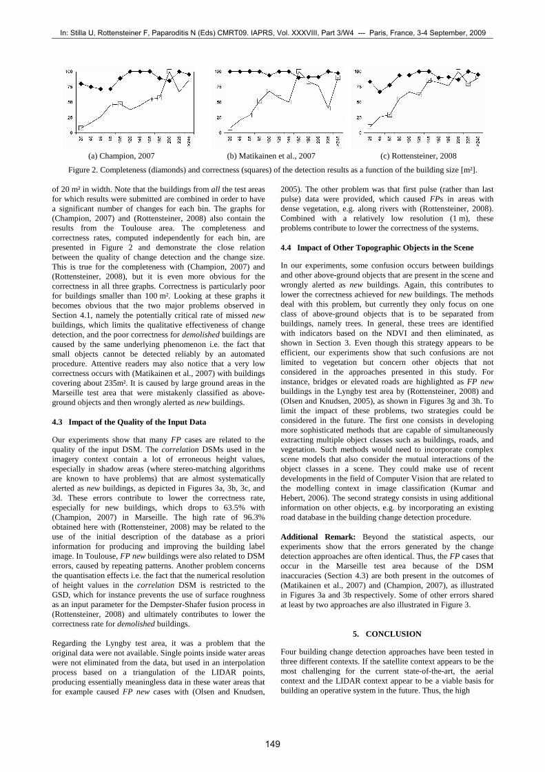
Figure 2. Completeness (diamonds) and correctness (squares) of the detection results as a function of the building size [m²].
of 20 m² in width. Note that the buildings from all the test areas for which results were submitted are combined in order to have a significant number of changes for each bin. The graphs for (Champion, 2007) and (Rottensteiner, 2008) also contain the results from the Toulouse area. The completeness and correctness rates, computed independently for each bin, are presented in Figure 2 and demonstrate the close relation between the quality of change detection and the change size. This is true for the completeness with (Champion, 2007) and (Rottensteiner, 2008), but it is even more obvious for the correctness in all three graphs. Correctness is particularly poor for buildings smaller than 100 m². Looking at these graphs it becomes obvious that the two major problems observed in Section 4.1, namely the potentially critical rate of missed new buildings, which limits the qualitative effectiveness of change detection, and the poor correctness for demolished buildings are caused by the same underlying phenomenon i.e. the fact that small objects cannot be detected reliably by an automated procedure. Attentive readers may also notice that a very low correctness occurs with (Matikainen et al., 2007) with buildings covering about 235m². It is caused by large ground areas in the Marseille test area that were mistakenly classified as above-ground objects and then wrongly alerted as new buildings. 4.3 Impact of the Quality of the Input Data
Our experiments show that many FP cases are related to the quality of the input DSM. The correlation DSMs used in the imagery context contain a lot of erroneous height values, especially in shadow areas (where stereo-matching algorithms are known to have problems) that are almost systematically alerted as new buildings, as depicted in Figures 3a, 3b, 3c, and 3d. These errors contribute to lower the correctness rate, especially for new buildings, which drops to 63.5% with (Champion, 2007) in Marseille. The high rate of 96.3% obtained here with (Rottensteiner, 2008) may be related to the use of the initial description of the database as a priori information for producing and improving the building label image. In Toulouse, FP new buildings were also related to DSM errors, caused by repeating patterns. Another problem concerns the quantisation effects i.e. the fact that the numerical resolution of height values in the correlation DSM is restricted to the GSD, which for instance prevents the use of surface roughness as an input parameter for the Dempster-Shafer fusion process in (Rottensteiner, 2008) and ultimately contributes to lower the correctness rate for demolished buildings. Regarding the Lyngby test area, it was a problem that the original data were not available. Single points inside water areas were not eliminated from the data, but used in an interpolation process based on a triangulation of the LIDAR points, producing essentially meaningless data in these water areas that for example caused FP new cases with (Olsen and Knudsen,
2005). The other problem was that first pulse (rather than last pulse) data were provided, which caused FPs in areas with dense vegetation, e.g. along rivers with (Rottensteiner, 2008). Combined with a relatively low resolution (1 m), these problems contribute to lower the correctness of the systems. 4.4 Impact of Other Topographic Objects in the Scene
In our experiments, some confusion occurs between buildings and other above-ground objects that are present in the scene and wrongly alerted as new buildings. Again, this contributes to lower the correctness achieved for new buildings. The methods deal with this problem, but currently they only focus on one class of above-ground objects that is to be separated from buildings, namely trees. In general, these trees are identified with indicators based on the NDVI and then eliminated, as shown in Section 3. Even though this strategy appears to be efficient, our experiments show that such confusions are not limited to vegetation but concern other objects that not considered in the approaches presented in this study. For instance, bridges or elevated roads are highlighted as FP new buildings in the Lyngby test area by (Rottensteiner, 2008) and (Olsen and Knudsen, 2005), as shown in Figures 3g and 3h. To limit the impact of these problems, two strategies could be considered in the future. The first one consists in developing more sophisticated methods that are capable of simultaneously extracting multiple object classes such as buildings, roads, and vegetation. Such methods would need to incorporate complex scene models that also consider the mutual interactions of the object classes in a scene. They could make use of recent developments in the field of Computer Vision that are related to the modelling context in image classification (Kumar and Hebert, 2006). The second strategy consists in using additional information on other objects, e.g. by incorporating an existing road database in the building change detection procedure. Additional Remark: Beyond the statistical aspects, our experiments show that the errors generated by the change detection approaches are often identical. Thus, the FP cases that occur in the Marseille test area because of the DSM inaccuracies (Section 4.3) are both present in the outcomes of (Matikainen et al., 2007) and (Champion, 2007), as illustrated in Figures 3a and 3b respectively. Some of other errors shared at least by two approaches are also illustrated in Figure 3.
5. CONCLUSION
Four building change detection approaches have been tested in three different contexts. If the satellite context appears to be the most challenging for the current state-of-the-art, the aerial context and the LIDAR context appear to be a viable basis for building an operative system in the future. Thus, the high
(a) Champion, 2007
(b) Matikainen et al., 2007
(c) Rottensteiner, 2008
149
In: Stilla U, Rottensteiner F, Paparoditis N (Eds) CMRT09. IAPRS, Vol. XXXVIII, Part 3/W4 --- Paris, France, 3-4 September, 2009 ¯¯¯¯¯¯¯¯¯¯¯¯¯¯¯¯¯¯¯¯¯¯¯¯¯¯¯¯¯¯¯¯¯¯¯¯¯¯¯¯¯¯¯¯¯¯¯¯¯¯¯¯¯¯¯¯¯¯¯¯¯¯¯¯¯¯¯¯¯¯¯¯¯¯¯¯¯¯¯¯¯¯¯¯¯¯¯¯¯¯¯¯¯¯¯¯¯¯¯¯¯¯¯¯¯¯¯¯¯

Figure 3. Evaluation Details (same colour code as Figure 1). FP new cases related to DSM errors (shadow areas), in Marseille streets (a)-(b) and Toulouse (c)-(d); (e)-(f) FN new cases (small changes); (g)-(h) FP new buildings related to bridges.
completeness rates for demolished buildings and the high correctness for unchanged buildings that could be achieved in these contexts highlight the effectiveness of the presented approaches in verifying the existing objects in the databases. The main limitation in terms of qualitative efficiency concerns the relatively high number of FN new buildings – up to 12.1% in the Marseille test area with (Rottensteiner, 2008) – that are mostly related to the object change size. The economical efficiency of the presented approaches seems to be promising, with 80-90% of the existing buildings requiring no further attention by the operator. These buildings are reported to be unchanged, which saves a considerable amount of manual work. In terms of the economical efficiency, the main limitation is a high number of FP demolished buildings that have to be inspected unnecessarily. Again, this is mainly caused by problems in detecting small changes. Areas of improvement should concern input data and methodologies. Thus, the resolution of LIDAR data (1 point / m²) used in this test appeared to be critical for the change detection performance: using higher density LIDAR data (e.g. 5-10 points / m²) should improve the situation. As far as methodology is concerned, new primitives should be used in the algorithms, in particular 3D primitives (representing e.g. the 3D roof planes or building outlines) that can now be reliably reconstructed with the 3D acquisition capabilities, offered by recent airborne/spaceborne sensors. Another concern should be the improvement of the scene models used in object detection such that they can deal with different object classes and their mutual interactions. By incorporating different object classes and considering context in the extraction process, several object classes could be detected simultaneously, and the extraction accuracy of all interacting objects could be improved. In this project, we learned how difficult it is to compare approaches of very different designs. To carry out a fair test, we chose to use the building label images and to limit the type of changes to demolished and new buildings. In addition, we chose to compare the building label images to the initial vector database, basing on a coverage rate featured by the parameter Th. Further investigations are necessary to study the actual impact of this parameter on the completeness and correctness rates. However, if we are aware of these drawbacks, we think that this scheme was sufficient to bring out some interesting findings. We also hope that our results – in conjunction with
those of e.g. the ARMURS3 project – will be helpful to create a nucleus of interested people, both in academia and private sector, and to speed up the progress in the vector change detection field.
REFERENCES
Breiman, L., Friedman, J. H., Olshen, R. A., Stone, C. J., 1984. Classification and regression trees. The Wadsworth Statistics / Probability Series, Wadsworth, Inc., Belmont, California.
Champion, N., 2007. 2D building change detection from high resolution aerial images and correlation Digital Surface Models. In: IAPRSIS XXXVI-3/W49A, pp. 197–202.
Champion, N., Boldo, D., 2006. A robust algorithm for estimating Digital Terrain Models from Digital Surface Models in dense urban areas. In: IAPRSIS XXXVI-3, pp. 111–116.
N. Champion, L. Matikainen, F. Rottensteiner, X. Liang, J. Hyyppä, 2008. A test of 2D building change detection methods: Comparison, evaluation and perspectives. In: IAPRSIS XXXVII – B4, pp. 297-304.
Heipke, C., Mayer, H., Wiedemann, C., Jamet, O., 1997. Automated reconstruction of topographic objects from aerial images using vectorized map information. In: IAPRS, XXXII, pp. 47–56.
Kumar, S. and Hebert, M.,, 2006. Discriminative random fields. International Journal of Computer Vision 68(2), pp. 179–201.
Matikainen, L., Kaartinen, K., Hyyppä, J., 2007. Classification tree based building detection from laser scanner and aerial image data. In: IAPRSIS XXXVI, pp. 280–287.
Mayer, H., 2008. Object extraction in photogrammetric computer vision. ISPRS Journal of Photogrammetry and Remote Sensing 63(2008), pp. 213-222.
Olsen, B., Knudsen, T., 2005. Automated change detection for validation and update of geodata. In: Proceedings of 6th Geomatic Week, Barcelona, Spain.
Pierrot-Deseilligny, M., Paparoditis, N., 2006. An optimization-based surface reconstruction from Spot5- HRS stereo imagery. In: IAPRSIS XXXVI-1/W41, pp. 73–77.
Rottensteiner, F., 2008 Automated updating of building data bases from digital surface models and multi-spectral images. In: IAPRSIS XXXVII – B3A, pp. 265-270. 3 http://www.armurs.ulb.ac.be. Last visited: 30 June 2009.
(a) Matikainen et al., 2007
(c) Rottensteiner, 2008
(e) Rottensteiner, 2008
(g) Rottensteiner, 2008
(b) Champion, 2007
(d) Champion, 2007
(f) Champion, 2007
(h) Olsen and Knudsen, 2005
150
CMRT09: Object Extraction for 3D City Models, Road Databases and Traffic Monitoring - Concepts, Algorithms, and Evaluation ¯¯¯¯¯¯¯¯¯¯¯¯¯¯¯¯¯¯¯¯¯¯¯¯¯¯¯¯¯¯¯¯¯¯¯¯¯¯¯¯¯¯¯¯¯¯¯¯¯¯¯¯¯¯¯¯¯¯¯¯¯¯¯¯¯¯¯¯¯¯¯¯¯¯¯¯¯¯¯¯¯¯¯¯¯¯¯¯¯¯¯¯¯¯¯¯¯¯¯¯¯¯¯¯¯¯¯¯¯