Embed Size (px)
Citation preview


A text book on Engineering Graphics, Class XII.
PRICE : Rs.
FIRST EDITION 2010 CBSE, IndiaREVISED EDITION 2019, CBSE
COPIES:
PUBLISHED BY : The Secretary, Central Board of Secondary Education,Shiksha Kendra, 2, Community Centre, Preet Vihar,
Delhi-110092
DESIGN, LAYOUT : Vijaylakshmi Printing Works Pvt. Ltd.B-117, Sector-5 Noida-201301, Ph.: 0120-2421977, 2422312
PRINTED BY :
Vijaylakshmi Printing Works Pvt. Ltd.B-117, Sector-5 Noida-201301, Ph.: 0120-2421977, 2422312

Shiksha Kendra, 2, Community Centre, Preet Vihar, Delhi-110 092 India

ACKNOWLEDGEMENTS
Shri Vineet Joshi, Chairman, CBSE
Smt. Chitralekha Gurumurthy, Director (Academics)
Dr. R.P. Chaurisiya, Former Vice Principal, Bharatiya Vidya Bhavan, K.G. Marg, New Delhi
Shri Amrit Pal Singh, Dy. Director Power Training Institute, Badarpur, New Delhi
Dr. S.M. Kapur, Former HOS, Mukherjee Memorial Sr. Secondary School, Shahdara, Delhi
Shri Arvind Kr. Singh Chauhan, Lecturer, Modern School, Vasant Vihar, New Delhi
Smt. G.M. Prema, Lecturer, Shyama Prasad Vidyalaya, Lodi Estate, New Delhi
Shri Hitesh Gupta, Lecturer, G.B. Pant Sarvodaya Bal Vidyalaya, Srinivas Puri, New Delhi
Smt. Soumya N.M., Lecturer, Delhi Kannada Sr. Sec. School, Lodi Estate, New Delhi
Shri Surajit Chatterjee, Lect. Bal Bharati Public School, Ganga Ram Hospital Marg, New Delhi
Shri Pawan Amrut Kumar, Graphics Developer, NIC, New Delhi
Dr. Srijata Das, Education Officer, CBSE, Delhi
CBSE ADVISORS
CONVENOR
EDITING TEAM
DEVELOPMENT TEAM
MEMBER COORDINATOR
Dr. R.P. Chaurisiya, Former Vice Principal, Bharatiya Vidya Bhavan, K.G. Marg, New Delhi

Design is an integral aspect of the world around us. Every day, we are inundated
with images of current generation products such as automobiles, air crafts, and so on.
Design is crucial to each of these products.
Engineering Graphics is the language of communication for all engineers,
architects, interior decorators, apparel designers and many others. This is needed right
from conceiving the design of any product, upto the mass production stage and beyond
for modification and restructuring of Engineering Graphics finds its use in all fields
work relating to various products and their design.
As a first attempt, CBSE has prepared the text book for Class XI in Engineering
Graphics which has been published in June, 2010. Through Class XI text book you have
already gained an insight into the fundamentals of the subject Engineering Graphics.
In this book for class XII, you will learn about the representation of objects, such as
simple geometrical solids, simple machine blocks, in three dimension form i.e.
Isometric Projections of solids.
You will also begin to look afresh at the nature and function of several ordinary
household engineering hardware such as nuts, bolts, screws, washers, rivets etc. that
are essential to make a household run.
In addition, you will learn to assemble the various simple machine blocks correctly
in order to form a functional machine of appropriate use for household purposes or for
industry.
I would like to place on record my deep appreciation for all the subject experts and
practicing teachers who have put in their sincere efforts in the development of this
textbook. Appreciation is also due to Shri Shashi Bhushan, Director (Academics) & Dr.
(Smt.) Srijata Das, Education Officer for planning and execution of the work and
bringing out this publication.
It is hoped that students and teachers will benefit by making the best use of these
text books. Suggestions from the users for further improvement of these textbooks will
be highly appreciated.
Foreword
VINEET JOSHICHAIRMAN


having solemnly resolved to constitute India into a
and to secure to all its citizens :
social, economic and political;
of thought, expression, belief, faith and worship;
of status and of opportunity; and to promote among them all
2assuring the dignity of the individual and the unity and integrity of the Nation;
this twenty-sixth day of November, 1949, do
It shall be the duty of every citizen of India-
(a) to abide by the Constitution and respect its ideals and institutions, the National Flag and the NationalAnthem;
(b) to cherish and follow the noble ideals which inspired our national struggle for freedom;
(c) to uphold and protect the sovereignty, unity and integrity of India;
(d) to defend the country and render national service when called upon to do so;
(e) to promote harmony and the spirit of common brotherhood amongst all the people of India transcendingreligious, linguistic and regional or sectional diversities; to renounce practices derogatory to the dignity ofwomen;
(f) to value and preserve the rich heritage of our composite culture;
(g) to protect and improve the natural environment including forests, lakes, rivers, wild life and to havecompassion for living creatures;
(h) to develop the scientific temper, humanism and the spirit of inquiry and reform;
(i) to safeguard public property and to abjure violence;
(j) to strive towards excellence in all spheres of individual and collective activity so that the nation constantlyrises to higher levels of endeavour and achievement;
1(k) to provide opportunities for education to his/her child or, as the case may be, ward between age of 6 and 14
years.
1. Subs, by the Constitution (Forty-Second Amendment) Act. 1976, sec. 2, for "Sovereign Democratic Republic” (w.e.f. 3.1.1977)
2. Subs, by the Constitution (Forty-Second Amendment) Act. 1976, sec. 2, for "unity of the Nation” (w.e.f. 3.1.1977)
1. Subs. by the Constitution (Eighty - Sixth Amendment) Act, 2002

CONTENTS
ISOMETRIC PROJECTION
40
84
98
121
142
162
DRAWING OF MACHINE PARTS
BEARINGS
ROD JOINTS
TIE-ROD AND PIPE JOINTS
COUPLINGS
PULLEYS
1

ENGINEERING GRAPHICS
1.1 INTRODUCTION
The objects we look, around us, are in 3-Dimensional form. When we try to communicate the
structure of objects to others then we take the help of pictures / pictorial drawings. These
pictorial drawings are 'one plane' drawings because our mode of communication is paper which
has only two dimensions and these drawings show the object approximately as it appears to the
viewer.
In engineering, one plane drawings are extensively used in addition to the orthographic views of
an object to give the best understanding. So the practice of drawing the objects in one plane,
pictorial view, from the orthographic views is essential. There are three methods to draw the
pictorial drawings i.e.
1. Perspective Projection 2. Oblique Projection 3. Axonometric Projection
Perspective projection is mostly used by the artists, professional designers and architects to
show the views as it appears to the human eye. It appears to converge at a point, called vanishing
point. The Oblique projection is mostly used by the mathematicians and furniture
manufacturers. They impart third dimension at an angle to the two dimensional images, to show
the depth. The Axonometric projection differs from the other one plane views on the basis of
rotation angle along one or more of its axes relative to the plane of projection. It is extensively
used in mechanical engineering to show the blocks, machine parts, assemblies etc. It shows an
image of an object from a skew direction.
On the basis of inclination angle of the three principal axes to the plane of projection, the
axonometric projection is classified as, isometric projection, diametric projection and trimetric
projection.In isometric projection, all the angles between principal axes are equal while in
diametric projection, only two angles between three principal axes are equal and over 90°and in
trimetric projection, all the three angles are unequal and not less than 90°. As the principal axes
are inclined to the plane of projection so the measurement along them are also foreshortened.
But the most advantageous point of isometric projection is that it needs a single scale to measure
along each of the three axes. So in general, we use only isometric projection in engineering
practice.
CHAPTER 1

ENGINEERING GRAPHICS
1.2 ISOMETRIC PROJECTION
The isometric projection of an object is a
one plane view drawn with the object so
placed with respect to the plane of
projection that all the three principal
axes appear to be inclined to each other
at an equal angle of 120°.
The isometric scale is used to measure
the foreshortened length of dimensions
of any object to draw the isometric
projection. The steps of construction of
isometric scale are given below ; refer
Fig. 1.2
(i) Draw a horizontal line PQ.
(ii) Draw the true lengths on a
line PM inclined at 45° to
the horizontal line (say up
to 70 mm )
(iii) Draw another line PA at
30° to the horizontal line.
(iv) D r a w t h e v e r t i c a l
projection of all the
points of true length from
PM to PA.
(v) Complete the scale with the details as shown in the figure.
The lengths shown at the line PA are the isometric lengths to be used to draw the isometric
projection.
1.2.1 ISOMETRIC SCALE
Fig. 1.2

ENGINEERING GRAPHICS
1.2.2 POSITIONING OF SOLID
1.2.3 STEPS TO DRAW THE ISOMETRIC PROJECTION
The solids are mostly drawn by placing them as per their specific position with respect to vertical
plane (V.P.) and horizontal plane (H.P.), as discussed earlier in orthographic projection. If not
specified then they are drawn by placement in such a position which describes the shape of the
object in the best manner. Here after drawing the isometric projection we can observe the two
planes i.e. vertical plane and profile plane on two sides of the object, so to specify the direction
of viewing we mark an arrow towards the assumed Front of object as per conditions.
Fig. 1.3
1. Draw the base of the solid "with isometric scale" as per specified condition with
respect to V.P. and H.P. as per the rules of orthographic projection. It is called
Helping Figure.
2. Draw the centre of the helping figure and enclose the helping figure in a suitable
rectangle. Transfer the co-ordinates of centre to the sides of the enclosing rectangle
with centre lines.
3. Draw the three principal axes at 30°, 90° and 30° to the horizontal base line.
4. Copy the length of sides of helping figure's rectangle on the respective principal axis
and the height or length of the object on the third principal axis. It will give a box in
which the object will be perfectly/snugly fitted.
5. Copy the co-ordinates of centre and the vertices of the base on this box.
6. Join the visible edges by thick lines andAxis line by the centre line.
7. Complete the isometric projection with dimensioning and direction of viewing.
Now let us draw the isometric projection of regular solids.

ENGINEERING GRAPHICS
1.3 DRAWING OF ISOMETRIC PROJECTION
The isometric projection of different solids is drawn by keeping the three principal axis at 120° to
each other. The solids are drawn as per the specified condition with respect to V.P. and H.P. In
earlier class we have studied to draw the isometric projection of two dimensional laminae of
regular shapes. Here we will study to draw the isometric projection of single regular solids and
combination of two solids. As per the characteristics of regular solids, we can classify them as
follows:-
(i) Prisms
(ii) Pyramids
(iii) Cylinder and Cone
(iv) Frustum of Pyramids
(v) Sphere and Hemisphere
Prisms are the solids with two bases and rectangular faces. They can be kept horizontal by
resting on face or vertical by resting on base. Let us consider some examples to
understand it better.
A hexagonal prism of base side 30 mm and height of 70 mm resting on its base on
H.P. with two of its base sides parallel to V.P. Draw its isometric projection.
Refer Fig. 1.4 [(i) to (v)]
Steps (i) Draw the hexagon with isometric length of 30 mm.
(ii) Complete the helping figure by enclosing the hexagon in snugly fitted rectangle
and show centre lines of hexagon.
(iii) Draw the isometric box with OA length at the side of direction of viewing, OB
length at the opposite side and OC equal to ISO 70mm, is length of height of prism
on vertical line.
(iv) Copy all the points of hexagon and centre on the box.
(v) Join the visible edges by thick lines and axis by centre lines.
(vi) Complete the isometric projection of hexagonal prism with dimensioning and
direction of viewing.
1.3.1 PRISMS
Example 1:
Solution :

ENGINEERING GRAPHICS
Fig. 1.4

ENGINEERING GRAPHICS
Example 2 :
Solution :
Let us consider more examples of the prisms with the same steps of construction.
Example 3:
Solution :
A hexagonal prism of base side 30 mm and height of 70 mm resting on its face on
H.P. with two of its bases parallel to V.P. Draw its isometric projection.
Refer Fig 1.4 [ (i) to (iii) & (vi) to (vii)]
Steps (i) and (ii) will be same as above in example 1.
(iii) Draw the box with OA length at the side of direction of viewing, OB length on the
vertical line and OC length equal to isometric length of height of prism on the third
principal axis.
(iv), (v) & (vi) will be same as above in example 1.
Draw the isometric projection of a cube of side 50 mm.
Refer Fig. 1.5
In cube all the sides have equal length. So take isometric 50 mm on each principal
axis and complete the cube with thick lines, dimensioning, center line and
direction of viewing.
Fig. 1.5

ENGINEERING GRAPHICS
Example 4 :
Solution : (a)
Draw the isometric projection of square prism of 40 mm base edge and 60 mm axis
resting;
(a) On its base on H.P. keeping one of its base edges parallel to V.P.
(b) On its face on H.P. keeping its base perpendicular to V.P.
Refer Fig. 1.6 (a)
To draw the isometric projection of a vertical square prism with vertical axis and
one base side parallel to V.P., OA & OB equal to ISO 40 mm on each horizontal line
and OC equal to ISO 60 mm, on vertical line. Complete the isometric projection
with thick lines, dimensioning, center lines and direction of viewing.
Fig. 1.6
(b) Refer fig 1.6(b)
To draw the isometric projection of a square prism with horizontal axis and base
perpendicular to V.P. take OB equal to ISO 40 mm on the horizontal line on the side
of direction of viewing, OA equal to ISO 60 mm on another horizontal line and OC
equal to ISO 40 mm on vertical line. Complete the isometric projection with thick
lines, dimensioning, center lines and direction of viewing.

ENGINEERING GRAPHICS
Example 5:
Solution :
Example 6:
Solution:
Draw the isometric projection of an equilateral triangular prism of 50 mm base
side and 75 mm axis resting on its base in H.P. with one of its base edges parallel to
V.P. and near the observer.
Refer Fig 1.7
Steps (i) Draw the helping figure of triangle with iso 50 mm length with one of its base edges
parallel to V.P. in front (near the observer).
(ii) Draw the isometric box with OA and OB from helping figure and OC equal to
isometric 75 mm.
(iii) Copy the points of triangle and co-ordinates of center to isometric box.
(iv) Join the visible edges by thick lines and axis by center lines.
(v) Complete the isometric projection with dimensioning and direction of viewing.
An equilateral triangular prism of 50 mm base side and 70 mm length resting on one
of its rectangular faces on H.P. with its axis perpendicular to V.P. Draw its isometric
projection.
Refer Fig. 1.8
Fig. 1.7
HELPING FIGURE

ENGINEERING GRAPHICS
Steps (i) Draw the helping figure of triangle with iso 50 mm length with one of its base edge
in H.P.
(ii) Draw the isometric box with OA on the horizontal line towards the direction of
viewing, OB on the vertical line and OC equal to isometric 70 mm on another
horizontal line.
(iii) Copy the points of triangle and co-ordinates of centre to isometric box.
(iv) Join the visible edges by thick lines and axis by centre line.
(v) Complete the isometric projection with dimensioning and direction of viewing.
Draw the isometric projection of a pentagonal prism of 30 mm base side and 65 mm
axis. The axis of the prism is perpendicular to H.P. and one of its base edges is
perpendicular to V.P.
Refer Fig. 1.9
(i) Draw the helping figure of pentagon with iso 30 mm length with one of its base
edges perpendicular to V.P.
(ii) Draw the isometric box with OA & OB from helping figure and OC equal to iso 65
mm.
(iii) Copy the points of pentagon and co-ordinates of centre to isometric box.
Example 7:
Solution:
Steps
Fig. 1.8

ENGINEERING GRAPHICS
(iv) Join the visible edges by thick lines and axis by center line.
(v) Complete the isometric projection with dimensioning and direction of viewing.
A Pentagonal prism of base side 25 mm and axis length 55 mm is resting on its face
with its axis parallel to both H.P and V.P. Draw its isometric projection.
Refer fig 1.10
Example 8:
Solution:
Fig. 1.9
HELPING FIGURE
ISOMETRIC PROJECTION
Fig. 1.10
HELPING FIGURE

ENGINEERING GRAPHICS
Steps (i) Draw the helping figure of pentagon with iso 25 mm length with one of its base
edges in H.P.
(ii) Draw the isometric box with OA on the horizontal line parallel to the direction of
viewing, OB on the vertical line and OC equal to iso 55 mm on another horizontal
line.
(iii) Complete the isometric projection of pentagonal prism in this isometric box using
the same steps discussed in earlier examples.
Pyramids are the solids with a base and slant triangular faces. These faces meet at a point
called apex of the pyramid. In pyramids if they are kept on their base then they are called
upright / vertical pyramids but if they are kept on their vertex on H.P. then they are called
inverted pyramids.
Let us draw some examples.
Draw the isometric projection of a pentagonal pyramid of base side 35 mm and axis of 75
mm resting on its base on H.P. with one of its base sides parallel to V.P. and nearer to the
observer.
Refer Fig. 1.11 [(i) to (v)]
Steps (i) Draw the pentagon with iso 35 mm length and one of its base edges parallel to V.P.
and nearer to the observer.
(ii) Complete the helping view/figure by enclosing the pentagon in a snugly fitted
rectangle and show center lines of pentagon.
(iii) Copy the dimensions of helping figure i.e. OA and OB on the horizontal line as
shown and draw the center lines of pentagon in it.
(iv) Draw the vertical axis in upright position from the center of pentagon equal to iso
75 mm.
(v) Join the visible edges, starting from the vertex to base corners by thick lines.
(vi) Complete the isometric projection of pentagonal pyramid with direction of
viewing and dimensioning.
Draw the isometric projection of an inverted vertical pentagonal pyramid of base
side 35 mm and axis of 75 mm with one of its base sides parallel to V.P. and nearer
to the observer.
1.3.2 PYRAMIDS
Example 9:
Solution :
Example 10:

ENGINEERING GRAPHICS
Fig. 1.11

ENGINEERING GRAPHICS
Solution :
Example 11:
Solution :
Example12:
Solution:
Refer Fig. 1.11 [(i) to (iii) & (vi) to (vii)]
Steps (i) to (iii) will be same, as the previous example.
(iv) Draw the vertical axis in downward direction from the center of pentagon equal to
iso 75 mm.
(v) & (vi) will be same, as the previous example.
Draw the isometric projection of a square pyramid of base edge 50 mm and axial
height of 80 mm kept in inverted position with two of its base sides parallel to V.P.
Refer Fig. 1.12
A right triangular pyramid of base edge 50 mm and axial height of 80 mm is kept on
its base keeping one of its base sides parallel to V.P. and away from it. Draw its
isometric projection.
Refer Fig. 1.13
Fig. 1.12
ENGINEERING GRAPHICS
Fig. 1.13
Draw the isometric projection of an inverted triangular pyramid of base side 50
mm and axis of 80 mm keeping one of its base sides parallel to V.P. and nearer the
observer.
Refer Fig. 1.14
Example:13:
Solution :
HELPING FIGURE
Fig. 1.14
HELPING FIGURE
ISOMETRIC PROJECTION
ISOMETRIC PROJECTION

ENGINEERING GRAPHICS
Example 14:
Solution:
Example 15 :
Solution:
Draw the isometric projection of a hexagonal pyramid having base edge of 40 mm
and axis 70 mm resting on its base keeping two of its base sides parallel to the V.P.
Refer Fig. 1.15
Fig. 1.15
Draw the isometric projection of an inverted hexagonal pyramid of base edge 30
mm and height of 60 mm keeping two of its base sides parallel to V.P.
Refer Fig. 1.16
HELPING FIGURE
Fig. 1.16

ENGINEERING GRAPHICS
1.3.3 FRUSTUM OF PYRAMID
Example 16 :
Solution :
Example 17 :
Solution:
We are well aware about the frustum of pyramids that they are the truncated lower
portion of the pyramid. So, the frustum of pyramid has one end with shorter base edge and
the other end with longer base edge. To draw the isometric projection of the frustum of
pyramid, we have to draw the helping figures for both the ends.
Let us draw some examples.
Draw the isometric projection of a frustum of square pyramid of shorter base
edge 30 mm and longer base edge 50 mm with the axial height of 60 mm, kept on
H.P. on its longer end and two of its base edges are parallel to V.P.
Refer Fig 1.17 [(i) to (v)]
Steps (i) Draw the helping figures of both the base ends with iso 30 mm and iso 50 mm.
(ii) Complete the helping figures by enclosing rectangle and centre lines.
(iii) Draw the isometric box with OA length on the side of direction of viewing, OB
length on the another horizontal line and OC equal to iso 60 mm, height of
frustum of pyramid on vertical line.
(iv) Draw the center lines on the upper end of the isometric box and mark centre as M.
(v) Copy the lengths of helping figures of shorter end 'oa' and 'ob' by placing 'm' on 'M'.
(vi) Mark all the points of shorter end helping figure on the upper end of isometric box
and all the points of longer end helping figure on the lower end of isometric box.
(vii) Join the visible edges by thick lines and axis by center line.
(viii) Complete the isometric projection of frustum of square pyramid with
dimensioning and direction of viewing.
Draw the isometric projection of a frustum of square pyramid of shorter base
edge 30 mm and longer base edge 50 mm with the axial height of 60 mm, kept on
H.P. on its shorter end and two of its base edges are parallel to V.P.
Refer Fig 1.17 [(i) to (iii) & (vi) & (vii)]
Steps (i) to (iii) will be same as the previous example.
(iv) Draw the center lines of the lower end of the isometric box as the shorter end of
the given frustum of pyramid is at lower end and mark center as M.
(v) will be same as the previous example.
(vi) Mark all the points of shorter and helping figure on the lower end of isometric box
and all the points of longer end helping figure on the upper end of isometric box.
(vii) & (viii) will be same as the previous example.

ENGINEERING GRAPHICS
Fig. 1.17
HELPING FIGURE
HELPING FIGURE
(i)(ii)
(iii)
(iv)(v)
(vi) (vii)

ENGINEERING GRAPHICS
Example 18 :
Solution:
Example 19 :
Solution:
Draw the isometric projection of the frustum of triangular pyramid having top
base edge 40 mm and bottom base edge 50 mm with a height of 75 mm resting on
its longer base keeping one of its base sides parallel to the V.P. and nearer to the
observer.
Refer Fig. 1.18
Fig. 1.18
A frustum of an inverted hexagonal pyramid of shorter base side 20 mm and
longer base side 40 mm and axial height of 65 mm is resting on its shorter end on
H.P. with two of its base sides perpendicular to V.P. Draw its isometric projection.
Refer Fig. 1.19
HELPING FIGURE HELPING FIGURE
Fig. 1.19
HELPING FIGURE
HELPING FIGURE

ENGINEERING GRAPHICS
Example 20 :
Solution :
1.3.4 CYLINDERAND CONE
Example 21:
Solution:
Draw the isometric projection of frustum of pentagonal pyramid having longer
base side 40 mm and shorter base side 30 mm with axis of 70 mm resting on its
longer base side keeping one of its base sides parallel to V.P. and nearer to the
observer.
Refer Fig. 1.20
Fig. 1.20
Cylinder and cone are the solids in which base is a circle. In our earlier class we have
studied that the circle is drawn in isometric projection by different methods. We can use
the “four centre method” or “circular arc method” to draw the circle in isometric
projection. The cylinders and cones are drawn with the same steps of prism and pyramids
except one additional step for drawing the ISO projection of circle.
Let us draw some examples.
Draw the isometric projection of a cylinder of diameter 40 mm and axial length of
70 mm lying on the H.P. keeping its axis parallel to H.P. and V.P.
Refer Fig. 1.21
HELPING FIGURE
HELPING FIGURE

ENGINEERING GRAPHICS
Steps (i) Draw the isometric box of a square prism of 40 mm base side and 70 mm axis by
keeping the axis parallel to both H.P. and V.P.
(ii) In the two rhombuses draw the ellipses by four center method (as learnt in
class XI).
(iii) Draw two common tangents to the two ellipses.
(iv) Draw the visible lines and curves by thick lines.
(v) Complete the isometric projection of cylinder with dimensioning and direction of
viewing.
Fig. 1.21
Draw the isometric projection of a cylinder of height of 75 mm and diameter of 50
mm resting on its base keeping the axis parallel to V.P.
Refer Fig. 1.22
Example 22 :
Solution:

ENGINEERING GRAPHICS
Fig. 1.22
Draw the isometric projection of cone of diameter 40 mm and axis of 60 mm
resting on its base on H.P. and its axis is perpendicular to H.P. and parallel to V.P.
Refer Fig. 1.23
Example 23 :
Solution :
Fig. 1.23

ENGINEERING GRAPHICS
Example24 :
Solution:
Example 25 :
Solution:
Draw the isometric projection of an inverted cone of diameter 50 mm and axis of
80 mm keeping its axis perpendicular to H.P.
Refer Fig 1.24
Fig. 1.24
Draw the isometric projection of a frustum of a cone of diameter 30 mm at
smaller end, diameter 50 mm at bigger end and the axial height is 80 mm. It is
resting on its bigger end on H.P. keeping its axis vertical.
Refer Fig 1.25
Fig. 1.25

ENGINEERING GRAPHICS
1.3.5 SPHERESAND HEMISPHERES
Example 26 :
Solution :
Spheres are the solids without any edge or vertex. When they are visualized from any
direction they look like a circle. Due to this unique characteristic of sphere, they have
only one point of contact with the plane of rest. This point of contact will not be visible in
isometric projection of sphere.
Let us draw some examples.
Draw the isometric projection of a sphere of diameter 50 mm.
Refer Fig. 1.26
Steps (i) Draw isometric projection of square in horizontal plane with side of ISO 50 mm
length.
(ii) Draw the center lines of this square.
(iii) Take a point O in vertically upward direction equal to ISO 25 mm (Isometric length
of radius of sphere) from the center of the square drawn in step 2.
(iv) Taking this point O as a center and TRUE 25 mm as the radius, draw a circle.
(v) This drawn circle is the isometric projection of the given sphere.
Note: Isometric projection of a sphere is always a circle of true-radius whose centre is located by
taking height = isometric radius.
Fig. 1.26

ENGINEERING GRAPHICS
Example 27 :
Solution:
Draw the isometric projection of a hemisphere of 60 mm diameter resting on its
curved surface on H.P.
Refer Fig. 1.27
Steps (i) Draw the isometric projection of a circle of 60 mm diameter ie. ellipse by four
center method in H.P. (as learnt in class XI).
(ii) Draw an arc with O as center and half of the major axis of ellipse as radius towards
lower half of the ellipse.
(iii) Complete the hemisphere with dimensioning, center lines and direction of
viewing, using conventional lines.
1. Draw an isometric projection of a triangular prism having base edge of 65 mm and axial
height of 85 mm, resting on one of its rectangular faces on H.P. keeping its base
perpendicular to V.P.
2. Draw an isometric projection of a pentagonal prism of base side of 35 mm and axial length
of 60 mm kept on one of its face edges on H.P. with one rectangular face parallel to H.P. on
top and axis is perpendicular to V.P.
3. A square pyramid is resting on its base, having base edge 60 mm and axial height of 70 mm
with its base edge parallel to V.P. Draw its isometric projection.
4. Draw an isometric projection of a hexagonal pyramid having base edge 35 mm and axis of
65 mm resting on its base on H.P. Keep two of its base sides perpendicular to V.P.
EXERCISE
Fig. 1.27

5. Draw an isometric projection of a frustum of hexagonal pyramid of shorter base side 25
mm and longer base side 45 mm and height 75 mm. It is resting on its larger base on H.P.
with two of its base sides parallel to V.P.
6. Draw an isometric projection of a hemisphere of 50 mm diameter kept with circular face
on H.P.
We have already studied and learnt the isometric projection of single geometrical solids in
vertical position and horizontal position by using box method from the helping figure of the solid.
Now we will learn to draw isometric projection of two geometrical solids placed together i.e. one
resting (either vertical or horizontal) on top of the other solid (either vertical or horizontal). This
is known as ‘combination of solids’. As per the course content in our syllabus we are going to
restrict our combination using two solids only, excluding the frustums.
The study of the combination of solids will help us in understanding the machine blocks to be done
in isometric projection and assembly drawings of the functional machine components at a later
stage in Engineering Graphics.
Draw an Isometric Projection of a square prism having side of the square = 30 mm
and height = 54 mm standing (upright) and centrally on a flat square slab of
thickness = 26 mm and its base side = 52 mm.
1.4 COMBINATION OF TWO SOLIDS
Example : 28
Fig. 1.28

ENGINEERING GRAPHICS
Steps:
Example: 29
1. Draw an isometric projection of the square slab.
2. Indicate the center of the top face with centre lines.
3. Around the centre ‘O’ draw the rhombus of the square prism and lift it upto its
required height.
4. Join all the visible edges (no hidden lines) of the two solids by using thick lines.
5. Complete the isometric projection of the two solids with dimensioning, direction
of viewing and their common axis using convention lines.
Draw an Isometric Projection of 32 mm cube resting centrally on the top face of
an equilateral triangular prism having 50 mm base side and height = 30 mm. One
rectangular face of the prism is away from the observer and kept parallel to the
V.P.
HELPING FIGURE
Fig. 1.29

ENGINEERING GRAPHICS
Steps:
Example: 30
1. Draw an isometric projection of the box that encloses an equilateral triangular
prism having one of its rectangular face at the back.
2. Indicate the centre of the top face with convention lines.
3. Around the centre ‘O’draw the rhombus of cube and lift it upto its height equal to
the side of cube.
4. Join all the visible edges (no hidden lines) of the two solids by using thick lines.
5. Complete the isometric projection of the two solids with dimensioning, direction
of viewing and their common axis using conventional lines.
Draw an Isometric Projection of a square pyramid resting vertically and centrally
on the top pentagon face of a pentagonal prism, having one rectangular face
parallel to V.P. while closer to the observer. Side of the square base = 30 mm,
height of pyramid = 50 mm, side of the pentagon = 34 mm and height of the prism
= 52 mm.
Fig. 1.30

ENGINEERING GRAPHICS
Steps:
Example: 31
1. Draw an isometric projection of the box that encloses pentagonal prism having
one of its rectangular face, in front, parallel to V.P.
2. Indicate the centre of the top face with conventional lines.
3. Around the centre ‘O’ draw the rhombus of the square base of the pyramid. Draw
the axis of the pyramid from the centre to apex.
4. Join all the visible edges (no hidden lines) of the two solids by using thick lines.
5. Complete the isometric projection of the two solids with dimensioning, direction
of viewing and their common axis using conventional lines.
Draw an Isometric Projection of an equilateral triangular pyramid resting
vertically and centrally with one base edge, at the back, parallel to V.P. on the
top face of a hexagonal prism having two of its rectangular faces parallel to V.P.
Side of the triangle = 34 mm, height of pyramid = 50 mm, side of the hexagon = 30
mm and height of the prism = 60 mm.
HELPING FIGURE
Fig. 1.31
HELPING FIGURE

ENGINEERING GRAPHICS
Steps:
Example: 32
1. Draw an isometric projection of the box that encloses hexagonal prism having
two faces parallel to V.P.
2. Indicate the centre of the top hexagon face with conventional lines.
3. Around the centre ‘O’ draw the equilateral triangle base of the pyramid. Raise
the axis of the pyramid from the center to apex.
4. Join all the visible edges (no hidden lines) of the two solids by using thick lines.
5. Complete the isometric projection of the two solids with dimensioning, direction
of viewing and their common axis using conventional lines.
Draw an Isometric Projection of a vertical regular pentagonal pyramid resting
centrally, having one base edge away from the observer parallel to V.P., on top of
a vertical cylinder. Side of the pentagon = 32 mm, height of pyramid = 50 mm,
diameter of cylinder = 80 mm and height of cylinder = 40 mm.
HELPING FIGURE
Fig. 1.32

ENGINEERING GRAPHICS
Steps:
Example: 33
1. Draw an isometric projection of the box that encloses a cylinder. Use four centre
method to form the top elliptical face of the cylinder.
2. Indicate the centre of the top face with conventional lines.
3. Around the centre ‘O’ draw a pentagonal base of the pyramid. Draw the axis of
the pyramid from the centre to apex.
4. Join all the visible edges (no hidden lines) of the two solids by using thick lines.
5. Complete the isometric projection of the two solids with dimensioning, direction
of viewing and their common axis using conventional lines.
Draw an Isometric Projection of a right circular cone resting vertically and
centrally on the top of pentagonal slab having one of its rectangular face
perpendicular to the observer. Side of pentagon = 46 mm, thickness of slab = 30
mm, diameter of cone = 40 mm and height of cone = 60 mm.
HELPING FIGURE
Fig. 1.33

ENGINEERING GRAPHICS
Steps:
Exmple : 34
1. Draw an isometric projection of the box that encloses a pentagonal prism having
one rectangular face perpendicular to V.P.
2. Indicate the centre of the top pentagonal face with conventional lines.
3. Around the centre ‘O’ draw a rhombus for the circular base of cone. Using four
centre method draw an ellipse inside. Draw the axis of the cone from the centre
of base to apex.
4. Join all the visible edges (no hidden lines) of the two solids by using thick lines.
5. Complete the isometric projection of the two solids with dimensioning, direction
of viewing and their common axis using conventional lines.
Draw an Isometric Projection of hemisphere resting centrally on its curved
surface, on the top horizontal rectangular face of an equilateral triangular prism,
keeping two triangular ends parallel to the V.P. Side of equilateral triangle = 50
mm, length of the prism = 70 mm and diameter of the hemisphere = 60 mm.
HELPING FIGURE
Fig. 1.34

ENGINEERING GRAPHICS
Steps:
Example: 35
1. Draw an isometric projection of the horizontal box that encloses an equilateral
triangular prism with a rectangular face on top.
2. Indicate the centre of the top rectangular face with conventional lines.
3. From the centre ‘O’ draw the axis equal to isometric radius of the hemishphere to
point P. Around the centre ‘P’ draw rhombus. Use four center method to form the
top elliptical face. Draw an arc to complete the curved surface.
4. Join all the visible edges (no hidden lines) of the two solids by using thick lines.
5. Complete the isometric projection of the two solids with dimensioning, direction
of viewing and their axes as applicable, using conventional lines.
Draw an Isometric Projection of a sphere resting centrally on a rectangular face
of a horizontal hexagonal prism having its hexagonal ends perpendicular to V.P.
Side of hexagon = 30 mm, length of the prism = 80 mm and diameter of sphere = 60
mm.
HELPING FIGURE
Fig. 1.35

ENGINEERING GRAPHICS
Steps:
Example: 36
1. Draw an isometric projection of the horizontal box that encloses a hexagonal
prism having rectangular face on top.
2. Indicate the centre of the top rectangular face with conventional lines.
3. From the centre ‘O’ draw the axis equal to isometric radius of sphere to point
‘O1’. From the centre ‘O1’ draw a full circle equal to true radius of sphere.
4. Join all the visible edges (no hidden lines) of the two solids by using thick lines.
5. Complete the isometric projection of the two solids with dimensioning, direction
of viewing and their axes, as applicable, using conventional lines.
Draw an Isometric Projection of a right circular cone resting vertically and
centrally on the top horizontal rectangle of a pentagonal prism having its axis
parallel to H.P. and V.P. both. Side of pentagon = 34 mm, length of the prism = 80
mm, diameter of the cone = 44 mm and height of cone = 60 mm.
HELPING FIGURE
Fig. 1.36

ENGINEERING GRAPHICS
Steps:
Example: 37
1. Draw an isometric projection of horizontal box that encloses a pentagonal prism
having one rectangular face on top.
2. Indicate the centre of the top rectangular face with conventional lines.
3. Around the centre 'O' draw a rhombus of the circular base of cone. Using four
centre method draw an ellipse inside. Draw the axis of cone from the centre to
the apex.
4. Join all the visible edges (no hidden lines) of the two solids by using thick lines.
5. Complete the isometric projection of the two solids with dimensioning, direction
of viewing and their axes as applicable, using conventional lines.
Draw an Isometric Projection of a vertical regular hexagonal pyramid resting
vertically and centrally having two of its base edges perpendicular to V.P. on the
top rectangular face of a horizontal square prism with its square ends
perpendicular to V.P. Side of the square = 50 mm, length of the prism =100 mm,
side of the hexagon = 30 mm and height of the pyramid = 60 mm.
HELPING FIGURE
Fig. 1.37

ENGINEERING GRAPHICS
Steps:
1. Draw an isometric projection of square prism in horizontal position.
2. Indicate the centre of the top rectangular face with conventional lines.
3. Around the centre 'O' draw hexagonal base of the pyramid. Draw the axis of the
pyramid from the centre to the apex.
4. Join all the visible edges (no hidden lines) of the two solids by using thick lines.
5. Complete the isometric projection of the two solids with dimensioning, direction
of viewing and their axes, as applicable, using conventional lines.
1. BELOW: HEMISPHERE 2. BELOW: HEXAGONAL SLAB
ABOVE: CYLINDER ABOVE: PENTAGONAL PRISM
COMMONAXIS: VERTICAL COMMONAXIS: VERTICAL
Draw the isometric projection of combination of solids as given below. Draw the axis of each solid.

ENGINEERING GRAPHICS
3. BELOW: CIRCULAR SLAB 4. BELOW: CIRCULAR SLAB
ABOVE: HEXAGONAL PRISM ABOVE: PENTAGONALPRISM
COMMONAXIS : VERTICAL AXIS: VERTICAL AND HORIZONTAL
5. BELOW: CIRCULAR SLAB 6. BELOW: CUBE
ABOVE: EQUILATERALTRIANGULAR PRISM ABOVE: CONE
AXIS: VERTICAL AND HORIZONTAL COMMONAXIS: VERTICAL

ENGINEERING GRAPHICS
7. BELOW: CIRCULAR SLAB 8. BELOW: EQUILATERAL HORIZONTAL
TRIANGULAR PRISM
ABOVE: HEXAGONALPRISM ABOVE: SQUARE PYRAMID
AXIS: VERTICAL AND HORIZONTAL AXIS: HORIZONTAL AND VERTICAL
9. BELOW: EQUILATERALTRIANGULAR SLAB 10. BELOW: HEXAGONAL SLAB.
ABOVE: CYLINDER ABOVE: HEMISPHERE
COMMONAXIS : VERTICAL COMMON AXIS : VERTICAL

ENGINEERING GRAPHICS
11. BELOW: CIRCULAR SLAB 12. BELOW: HORIZONTALHEXAGONAL PRISM
ABOVE: PENTAGONAL PYRAMID ABOVE: CYLINDER
COMMON AXIS : VERTICAL AXIS: HORIZONTAL AND VERTICAL
13. BELOW: EQUILATERALTRIANGULAR SLAB 14. BELOW: HEMISPHERE
ABOVE: HEXAGONALPYRAMID ABOVE: SPHERE
COMMONAXIS : VERTICAL COMMONAXIS : VERTICAL

ENGINEERING GRAPHICS
15. BELOW: CIRCULAR SLAB 16. BELOW: HORIZONTAL HEXAGONAL PRISM
ABOVE: HEXAGONAL PYRAMID ABOVE: RIGHT CIRCULAR CONE
COMMONAXIS : VERTICAL AXIS: HORIZONTAL AND VERTICAL

ENGINEERING GRAPHICS
2.1 INTRODUCTION
2.2 SCREW THREAD
In our day to day life, we come across many objects where bolts and nuts are used to join two
pieces together. For example we use wooden furnitures like desks, stools, tables etc. in school,
showing bolts, nuts and screws. Such machine parts which are used to connect two pieces
together are called as fasteners. There are two types of fasteners, viz, temporary fasteners and
permanent fasteners. Threaded fasteners like bolt and nut are temporary fasteners. The process
of joining different machine parts of machine or engineering products is called as fastening.
Permanent fastening such as welding, riveting etc. join two parts together permanently and they
cannot be separated without breaking the fastening, but in the case of temporary fastening, the
parts are joined together temporarily and can be separated easily without breaking the
fastening.
A continuous helical groove cut along the outer circumference of a cylindrical surface is called a
screw thread. A screw thread is an operating element of temporary fastening. Screw thread
occurs on practically all engineering products. Fig. 2.1 shows a screw thread/helical groove on a
cylindrical rod.
2
Fig. 2.1
Screw threads are widely used for temporary fastening as well as for transmission of power from
one machine part to another
SCREW THREAD

ENGINEERING GRAPHICS
Fig.2.2
2.3 TERMS USED IN THREADS / SCREW THREADS
The various terms in connection with screw threads are given below. Refer Fig.2.2
(i) EXTERNALTHREAD
It is a continuous helical groove or ridge cut along the external surface of the
cylinder, e.g. threads on bolts, studs, screws etc. Fig. 2.2(a) shows an external
thread.
(ii) INTERNALTHREAD
It is a thread on the internal surface of a hollow cylinder. Fig. 2.2(b) shows the
internal threads, e.g. threads of a nut.
(iii) SCREW PAIR
The bolt and nut together are called a screw pair. One or more such pairs are used
to join two parts.

ENGINEERING GRAPHICS
(iv) PARALLEL AND TAPER THREAD
Athread formed on the surface of a cylinder is called as parallel or straight thread.
Refer Fig 2.3(A)
(v) RIGHT HANDAND LEFT HAND THREADS
Consider any nut and bolt. Hold the bolt firmly in left hand and rotate the nut
clockwise by the right hand, the nut will ‘screw-on’ the bolt, these threads are
right handed (RH) threads.Anut with left hand screw thread when assembled with
a stationary mating bolt, ‘screw-off’ the bolt for clockwise rotation. It is
abbreviated as LH thread.
Observe that mostly the bolts and nuts that we use in daily life have RH thread.
Also we can observe that all the jewellery mating pieces have LH thread.
(vi) PITCH, P
It is "the distance between the corresponding points on the adjacent thread
surface, measured parallel to the axis". Refer Fig. 2.2 (A)
Fig. 2.3
A thread formed on the surface of a cone called as taper thread. Refer Fig. 2.3(B)

ENGINEERING GRAPHICS
(vii) LEAD,L
It is "the distance moved by a nut or bolt in the axial direction in one complete
rotation".
(viii) SINGLE STARTAND MULTI STARTTHREADS
When only one helix, forming the thread runs on a cylinder, it is called as single
start thread. If more then one helices run on a cylinder, it is called as multi start
threads.
i.e. L=P in the case of single start
L=2P in the case of double start
L=3P for triple start and so on.
(ix) CREST
It is the edge of the thread surface farthest from the axis, in case of external
thread and nearest to the axis, in case of internal thread
(x) ROOT
It is the edge of the thread surface nearest to the axis in case of external thread
and farthest from the axis, in case of internal thread.
(xi) FLANK
The surface connecting crest and root is called as flank.
(xii) THREADANGLE
It is "the angle between the flanks measured in an axial plane".
(xiii) MAJOR DIAMETER OR OUTSIDE DIAMETER
It is the diameter of an imaginary coaxial cylinder just touching the crest of
external threads or roots of internal threads. It is the largest diameter of a screw
thread.
(xiv) MINOR DIAMETER OR ROOT DIAMETER OR CORE DIAMETER
It is the diameter of an imaginary co-axial cylinder just touching the roots of
external threads or crest of internal threads.
(xv) NOMINALDIAMETER
It is the diameter of the cylinder from which external threads are cut out. The
screw/bolt is specified by this diameter.

ENGINEERING GRAPHICS
(xvi) FORM / PROFILE OF SCREWTHREAD
Fig. 2.4
The section of a thread cut by a plane containing the axis is known as the form of the screw thread.
It is also called the profile of the thread. Refer Fig. 2.4
2.4 STANDARD PROFILE / FORM OF SCREW THREADS
There are two basic screw thread profiles. viz.
(a) Triangular or 'V' thread
(b) Square thread.
When the thread has a triangular or V-cross section, it is called as V-threads. All types of
V-threads have inclined flanks making an angle between them. In the practical use of the
threads, a clearance must be provided between the external and internal threads.
V-threads are used "to tighten two parts together" as in bolts and nuts, studs and nuts,
screws etc.
For interchangeability between the screws and nuts of the same nominal diameter and
form, various countries have standardized V-thread profiles. A few such standard thread
forms are given in our syllabus namely
(i) B.S.W. thread
(ii) Metric thread
(a) TRIANGULAR OR 'V' THREAD

ENGINEERING GRAPHICS
(b) SQUARE THREAD
2.4.1 PROFILE OF B.S.W. THREAD
Example 1:
Solution
When the thread has square cross section it is called as square thread. Flanks of square
threads are vertical and parallel to each other. “Square threads are used for power
transmission” on feed mechanism of machine tools, screw jacks etc, as they offer less
frictional resistance. In our syllabus we are going to study about the standard profile/
form of a few square threads viz.
(i) Square thread
(ii) Knuckle thread
British standard whitworth (B.S.W.) thread is the most widely used form in British
practice. Let us now learn to draw the standard profile of B.S.W. thread.
Draw to scale 1:1, standard profile of B.S.W. thread, taking pitch = 40 mm. Give
standard dimensions.
Fig. 2.5

ENGINEERING GRAPHICS
Steps Involved
2.4.2 METRIC THREAD
Example 2:
(i) Draw vertical centre lines separated by the distance of P/2, (P/2=20 mm).
(ii) Draw two horizontal lines separated by a distance of major diameter D=0.96P.
(iii) One sixth of 'D' is cut off parallel to the axis of the screw at top and bottom, to draw
the horizontals for minor diameter, d= 0.64P.
(iv) Draw the basic or fundamental triangles within the D lines, such that the angle
between the flanks is 55°.
(v) Draw arcs at crest and roots, to make it round by any suitable method. The method
is shown clearly in Fig. 2.5, or radius of the arc can be taken as r= 0.137P.
(vi) Complete the profile and hatching is done as shown in Fig. 2.5, to represent the
external thread.
(vii) Standard dimensions are to be done as shown in the above figure.
The Bureau of Indian standards (BIS) has recommended the adoption of ISO (INTERNATIONAL
ORGANISATION FOR STANDARDISATION) profile with the metric screw thread system. In metric
thread, the external and internal thread vary in shape. It can also be called as unified thread. In
general, this ISO-metric thread will be specified using the basic designation.
The basic designation consist of the letter M followed by the nominal size (major diameter in mm)
and followed by the pitch in mm. For example M20 x 1.5 means the major diameter of the metric
thread is 20mm and the pitch is 1.5mm. Let us now draw the standard profiles of metric screw
thread.
Draw to scale 1:1, the standard profile of metric screw thread (external) taking
enlarged pitch as 50mm. Give standard dimensions.

ENGINEERING GRAPHICS
Solution:
(i) Draw vertical centre lines P/2 apart i.e. 50/2=25mm apart.
(ii) Draw horizontals to indicate D, (D=0.866), apart.
(iii) Cut off one eighth of D at the top and one sixth of D at the bottom or draw
horizontals to indicate d=0.61P.
(iv) Draw the slanting lines representing the sides of the thread. Here the angle
between the flanks is 60°.
(v) Make the crest flat and roots round. Roots are made round by any suitable method.
(vi) Hatching is done as shown in Fig. 2.6. This lower hatched profile shows the basic
form of the bolt.
(vii) Dimensioning is done as shown is Fig. 2.6
Fig. 2.6

ENGINEERING GRAPHICS
Fig. 2.7
Example 3 :
Solution :
Draw to scale 1:1, the standard profile of metric screw thread (internal) taking
enlarged pitch as 50mm. Give standard dimensions.
Refer Fig 2.7
Steps involved are similar to the previous example. Here the upper hatched profile shows the
basic form of nut.
Mechanisms of machine tools, valves, spindles, vice screws etc. are generally provided with
square threads. A square thread (SQ) is specified by nominal diameter and pitch. For example a
square thread of nominal diameter = 40 mm and pitch = 4mm is designated as SQ 40 X 4.
Let us now learn to draw the standard profile of a square thread, taking enlarged pitch as 60mm.
Refer Fig. 2.8
2.4.3 SQUARE THREAD
Solution :

ENGINEERING GRAPHICS
Steps Involved
(i) Draw two horizontals, P/2 apart i.e. 60/2= 30mm apart.
(ii) Draw a number of perpendiculars, 30mm apart so as to have a row of squares.
(iii) Hatching and dimensioning is done as shown in Fig. 2.8
Fig. 2.8
Knuckle thread is a modified form of square thread. Knuckle thread is a special purpose thread. It
is used in railway carriage coupling screws and on the neck of glass bottles.
Let us now draw the standard profile of Knuckle thread.
Draw to scale, 1:1, the standard profile of a Knuckle thread, taking enlarged pitch
as 40mm
2.4.4 KNUCKLE THREAD
Example 5 :

ENGINEERING GRAPHICS
Solution :
Steps Involved
Exercises
Refer Fig.2.9
Fig. 2.9
(i) Draw a thin centre line.
(ii) On either side of the centre line draw a row of tangential semi circles as shown
clearly in Fig. 2.9 Care should be taken in free flowing of semi circles into one
another.
(iii) Hatching and dimensioning is done as shown in Fig. 2.9.
1. Draw to scale 1:1, the standard profile of BSW thread, taking enlarged pitch as
30mm. Give standard dimensions.
2. Draw to scale 1:1, the standard profile of metric thread (external) taking enlarged
pitch as 60mm. Give standard dimensions.
3. Draw to scale 1:1, the standard profile of metric thread (internal) taking enlarged
pitch as 60mm. Give standard dimensions.
4. Draw to scale 1:1, the standard profile of square thread, taking enlarged pitch as
40mm. Give standard dimensions.
5. Draw to scale 1:1, the standard profile of knuckle thread, taking enlarged pitch as
60mm. Give standard dimensions.

ENGINEERING GRAPHICS
2.5 CONVENTIONAL REPRESENTATION OF THREADS
In actual projection, the edges of threads would be represented by helical curves. It takes a lot of
time to draw them. So, for convenience sake threads are generally shown by conventional
methods as recommended by B.I.S
The Bureau of Indian standards has recommended a very simple method of representing V-
threads. Fig 2.9 shows the simplified representation of external V-threads. According to
this convention, two continuous thick lines and two continuous thin lines are drawn to
represent crest and roots of the thread respectively. The limit of useful length of the
thread is indicated by a thick line perpendicular to the axis.
Fig. 2.9
2.5.1 CONVENTIONALREPRESENTATION OF EXTERNALTHREADS
2.5.2 CONVENTIONALREPRESETATION OF INTERNALTHREADS
Fig. 2.10 shows the representation of internal V-threads. It shows the sectional view of a
threaded hole in the front view. Thick line indicates the crest and thin line indicates the
root. Section (hatching) lines are extended up to thick lines. The side view shows a thick
circle representing the crest and roots by thin incomplete circle
Fig. 2.10
Exercise
1. Sketch freehand the conventional representation of internal and external threads,
given d = 30 mm.

ENGINEERING GRAPHICS
2.6 BOLTS
In day to day life, we can observe many machine parts joined by bolt and nut. Now, let us study
about the bolts.
A bolt consists of a cylindrical body with one end threaded and the other end converted into a
head. It is passed through clearance holes (diameter slightly more than nominal diameter of bolt)
in two or more aligned parts. A nut is screwed on the threaded end of the bolt to tighten the parts
together. Different types of bolts are used for different purposes. The shape of the head also
depends upon the purpose for which the bolt is used. The length of a bolt is its total length,
"excluding the height or thickness of bolt head". Bolt has external thread. An external thread is
represented by "discontinuous, minor diameter circle".
Fig. 2.11
We are going to study about the following types of bolts
(i) Hexagonal headed bolt
(ii) Square headed bolt
(iii) Tee headed bolt
(iv) Hook bolt
It is the most commonly used form of bolt. The head of a hexagonal
bolt is a hexagonal prism with a conical chamfer rounded off at an
angle of 30° on the outer end face. Chamfering is done to remove
sharp corners to ensure the safety of the user. The approximate
height/thickness of the bolt head is 0.8d (d is the diameter of the
bolt). A little portion (about 3 mm) of the threaded end should
remain outside the nut.
Let us now learn to draw the views of a hexagonal headed bolt.
2.6.1 HEXAGONALHEADED BOLT
Fig. 2.12

ENGINEERING GRAPHICS
EXAMPLE 6:
Solution:
Steps Involved
Draw to scale 1:1, the front view and side view of a hexagonal headed bolt of
diameter 30mm, keeping the axis parallel to H.P and V.P.
Refer Fig. 2.13a
Fig. 2.13a
(i) "Start with the view where circles are seen". Here the side view shows the circles
representing the shank. So, start with the side view.
(ii) Draw a circle of given diameter, d= 30mm
(iii) Draw another circle of diameter 0.8d (24mm), which is shown as
broken/discontinuous circle. (Broken part is shown in first quadrant) 'This inner
broken circle indicates that the thread on the bolt is an external thread'.
(iv) Draw another circle of diameter 1.5d+3 mm
(48 mm) to indicate the chamfering circle.
(v) Circumscribe hexagon around the chamfering
circle as in Fig. 2.13b using 30°— 60° degree
set square and minidrafter.
(vi) After completing the side view, the front view
will be drawn by taking projections. Project
the shank diameter (d= 30 mm) from the side
view. Draw a rectangle for the shank.
Fig. 2.13 b

ENGINEERING GRAPHICS
(vii) The end of the bolt is rounded and is done with the radius equal to the diameter of
the bolt. (R = d = 30mm)
(viii) Indicate the threaded portion (by projecting the 0.8d = 24mm circle with "thin
continuous lines") at the end of the shank for the length of 2d+6 mm =66mm
(ix) Draw the head of the bolt in the front view, by projecting the hexagon from the side
view. Size A/C (across corners) will be projected to get the width of the head.
Height of the head is taken as 0.8d= 24mm.
(x) The three faces of the hexagonal head with chamfering arcs is drawn by any of the
appropriate method.
(xi) The centers of chamfering arcs for the three faces may be located as shown in the
Fig. 2.13a
Keep in your mind that, in the front view, showing "three faces" of the hexagonal
head, show the upper corners of the head chamfered. In the front view showing
"two faces" of the hexagonal head, show the upper corners square.
It is also the common form of the bolt and is
generally used where the head of the bolt is
to be accommodated in a recess. The recess
itself is in the form of square in which the
head rests having a little clearance. The
square recess prevents the head from
rotating when the nut is screwed on or off.
Let us now learn how to draw the views of a
square headed bolt.
Draw to scale 1:1 the Elevation
and Plan of a square head bolt
when it axis is perpendicular
to H.P. Take the diameter of
the bolt as 24mm, and length
as 110 mm.
Refer Fig 2.15
2.6.2 SQUARE HEADED BOLT
Example 7 :
Solution :
Fig. 2.14

ENGINEERING GRAPHICS
Steps Involved
(i) Since the circles are seen in the top
view, start with the top view. Draw a
circle of diameter, d= 24 mm.
(ii) Within the ‘d’ circle, draw an another
discontinuous/broken circle of
diameter = 0.8d say 19.2 mm to the
bolt.
(iii) Draw the chamfering circle of
diameter =1.5d+3 mm, say 39 mm.
(iv) Circumscribe square around the
chamfering circle.
(v) Project the Front view from the top
view. Construct a rectangle of size
d x length of the bolt, 24x110mm.
The end of the bolt is rounded and is
done with the radius equal to the
diameter of the bolt. (R = d = 24 mm)
Indicate the threaded portion at the
end of the shank for the length of 2d+6
mm = 54 mm.
(vi) Bolt head is drawn by projecting the
front view. Construct a rectangle of
(1.5d+3)x0.8d say 39x19.2 mm.
(vii) Chamfering arc is drawn with radius of
R = 2d = 48 mm.
(viii) All the standard dimensions are given
as shown in the Fig. 2.14
Fig. 2.14

ENGINEERING GRAPHICS
Fig. 2.17
2.6.3 T-BOLT
Example 8 :
Solution:
The head of this bolt is just like the English alphabet 'T' Fig 2.16(I). It is "used in machine
tool tables". Corresponding T-slots are cut into the table [see Fig 2.16 (II)] to
accommodate the T-head of the bolt.Asquare neck is usually provided with the head.
Fig. 2.16
Draw to scale 1:1, the front view and side view of a T-Headed bolt of diameter
20mm. Keep the axis parallel to V.P and H.P.
Refer Fig. 2.17

ENGINEERING GRAPHICS
Steps Involved
2.6.4 HOOK BOLT/J-BOLT
Example 9 :
Solution :
(i) Start with the side view where circles are seen. Draw outer and inner circle of
diameter, d= 25 mm and 0.8d= 20 mm respectively, with inner circle discontinuous
or broken.
(ii) Then the front view is drawn with the shank and bolt head as shown clearly in the
Fig. 2.17.
Observe that the square cross section is shown by drawing thin cross lines.
(iii) Then complete the side view by projecting the T-head.
(iv) Dimensioning is done as shown in the Fig. 2.17.
Fig 2.18(b) shows the pictorial view of a Hook bolt. The head is in the form of a hook (J-
shape) which projects only in the side of the shank. The shank of the bolt passes through a
hole in one part only. The other part to be joined comes under the head of the bolt.Ahook
bolt is usually provided with a square neck to prevent its rotation while tightening.
Fig. 2.18
Draw to scale 1:1, the front view and plan of hook bolt with diameter 20 mm,
keeping the axis vertical. Give standard dimensions.
Refer Fig. 2.19

ENGINEERING GRAPHICS
Steps Involved
Exercises
(i) Start with the view having
circles. Here start with the
top view. Draw centre lines
and draw outer and inner
circle of diameter d= 20mm
and 0.8d= 16mm respectively.
To indicate the external
thread of the bolt, 0.8d circle
is drawn broken.
(ii) Complete the shank portion of
the front view as shown
clearly in the Fig. 2.19
(iii) Head portion of the front view
is complete and the square
cross section is shown as thin
cross lines.
(iv) Complete the hook portion of
the top view by projecting the
front view.
(v) Dimensioning is done as shown
in the Fig. 2.19
1. Draw to scale 1:1, the Front view and side view of a hexagonal head bolt of diameter
30 mm, keeping the axis parallel to H.P and V.P. The two opposite sides of the hexagonal
head is parallel to V.P. The length of the bolt is 120 mm.
2. Draw to scale 1:1, the Front view and top view of a hexagonal headed bolt of diameter
20mm, keeping the axis perpendicular to V.P. Give standard dimensions.
3. Draw to scale 1:1, the Front view and Side view of a hexagonal headed bolt of diameter
24mm, keeping the axis parallel to V.P and H.P. Two opposite sides of the hexagonal head is
perpendicular to V.P. Take the following dimensions.
Length of the bolt = 120mm
Threaded length of the bolt = 80mm
Fig. 2.19

ENGINEERING GRAPHICS
4. Draw to scale full size, the Front view and Side view of a square head bolt of diameter
24mm, keeping its axis horizontal.
5. Draw to scale 1:1, the Elevation and Plan of a square head bolt of diameter 30mm, when
its axis is perpendicular to H.P. Give standard dimensions.
6. Draw to scale 1:1, the Front elevation and Plan of a tee head bolt of diameter 24mm,
keeping the axis perpendicular to H.P.
7. Draw to scale 1:1, the Front view, Side view of a hook bolt with diameter 25mm, when its
axis parallel to V.P and H.P. Give standard dimensions.
2.7 NUTS
A nut is a machine element having a threaded hole that engages with the threaded end of the
bolt. There are different types of nuts in use. In our syllabus, we are going to study about
hexagonal nut and square nut.
Refer Fig. 2.20
The most commonly used type of nut is the
hexagonal nut. It is a hexagonal prism
provided with a threaded hole. Upper
corners of a nut are “chamfered” or
“rounded- off”. The angle of chamfer is
usually "30° with the base of the nut". The
chamfering gives arcs on the vertical faces
of the nut and circle on the top surface of
the nut. The chamfering circle on the top
surface touches the mid points of all the
sides of the nut which can be seen in the
top view. All dimensions of hexagonal bolt
and hexagonal nut are same except the height/thickness of the hexagonal head.
Let us now learn to draw the views of a hexagonal nut.
2.7.1 HEXAGONALNUT
Fig. 2.20

ENGINEERING GRAPHICS
Example 10 :
Solution
Steps Involved
Draw to scale 1:1, the front view, top view and side view of a hexagonal nut of size
M30, keeping the axis perpendicular to H.P. Give standard dimensions.
Refer Fig 2.21
Fig. 2.21
(i) Start with the top view, where circles are
seen. Draw a circle of diameter d = 30mm.
Describe this circle as discontinuous circle
to indicate the internal thread of a nut.
(ii) Draw an another circle of diameter 0.8d =
24mm
(iii) Draw the third circle which is of chamfering
circle of diameter 1.5d+3 = 48mm.
(iv) Circumscribe a hexagon around the
chamfering circle using the 30° - 60° degree
set square and mini drafter as shown in
Fig. 2.22.
NOTE : The size of chamfer
circle can be taken 1.5d
or 1.5d+3 in square / hex.
head bolt and nut.
Fig. 2.22

ENGINEERING GRAPHICS
Fig. 2.23
(v) Project the top view to get front view. Front view has three faces if nut is placed
across corner (A/C) and front view has two faces if the nut is placed across flats
(A/F). The common position for the nut isA/C.
(vi) Chamfering arcs in the front view may be done by any suitable method. One of the
methods is clearly shown in figure 2.21.
The alternate method is given below for your reference.
• On the front view, describe arc ABC [Fig.2.23] of radius 1.2d = 3mm. It cuts
the verticals inAand C. Here d = 25mm.
• Bisect the chord between D andAand between C and E.
• On the bisectors we shall expect to find the center of the arcs which pass
through DKAand CE.
• Join DK and bisect at right angles, thus locating the center of arc DKA.
Note that arc CE will also have the same radius.
(vii) Side view is projected from front view and top view. Side view and front view have
same height but different width.
(viii) Give the standard dimensions as shown in Fig 2.21.

ENGINEERING GRAPHICS
2.7.2 SQUARE NUT
Example 11:
Solution:
Steps Involved
A square nut is also one of the main forms of nut. It is a square prism provided with a
threaded hole. The upper corners of a square nut are chamfered in the same way as that of
a hexagonal nut. The dimensions of square head are same as that of square bolt except the
height/thickness. Now, let us learn to draw the views of a square nut.
Draw to scale 1:1, the Front elevation and Plan of a square nut of diameter 25mm,
keeping its axis vertical and two of the opposite edges of the square face parallel
to V.P.
Refer Fig 2.25
(i) Start with the top view. With same point as center, draw three circles of diameter d
= 25 mm, 0.8d = 20 mm, 1.5d =37.5 mm respectively.
Indicate the internal thread of the nut by drawing Ød circle discontinuous.
(ii) Circumscribe square around the chamfering circle of diameter 1.5d (37.5 mm)
(iii) Project the top view to get the front view. Front view is a rectangle of size
(1.5dxd) 37.5x25 mm.
(v) Chamfering arc in the front view is drawn with the radius R = 2d = 50 mm.
NOTE: If one face of the square nut is seen in the front view, make the corners squared.
(at 90° degree)
(v) Dimensioning is done as shown in Fig. 2.25.
Fig 2.24

ENGINEERING GRAPHICS
Fig. 2.26
Fig. 2.25
Draw to scale full size the Front View and Top View of a square nut of diameter
25mm, keeping its axis vertical with the diagonal on the square face parallel to V.P.
Example 12 :

ENGINEERING GRAPHICS
Solution :
Steps Involved :
Exercises :
Refer Fig. 2.26
(i) Start with the top view. Describe three circles of diameter d = 25mm, 0.8d = 20mm,
1.5d = 37.5mm respectively. (Ød circle is broken to represent the internal thread
of the nut.)
(ii) Circumscribe square around the chamfering circle as shown in Fig 2.26.
(iii) Project the Top View to draw the Front View
(iv) Complete the Front View as shown in Fig. 2.26.
NOTE: When two faces of square nut are seen in front view, the corners are chamfered.
ADDITIONAL INFORMATION
The hexagonal nut takes preference over the other nuts. A spanner is used to turn
the nut on or off the bolt. The jaws of the spanner come across the opposite flats of
the nut. The angle through which the spanner will have to be turned to get another
hold is only 60° in case of a hexagonal nut but 90° for a square nut. Though the
angle is 45° in case of the octagonal nut, it is rarely used due to its complicated
process of construction. So, it is more convenient to screw on a hexagonal nut than
a square nut in a limited space for turning the spanner.
NOTE :Assume missing dimensions proportionately
1. Draw to scale 1:1, the front elevation and plan of a hexagonal nut keeping axis
vertical, when two of the opposite sides of the hexagon are parallel to V.P. Give
standard dimensions, taking the diameter of bolt = 24 mm.
2. Draw to scale 1:1, the Plan and Front View of a hexagonal nut, taking nominal
diameter of the bolt = 30mm, keeping the axis perpendicular to H.P and two
opposite sides of the hexagon perpendicular to V.P. Give standard dimensions.
3. Draw to scale 1:1, the Front View and Top View of a square nut, taking nominal
diameter =30mm, keeping the axis perpendicular to H.P and two opposite sides of
the square perpendicular to V.P. Give standard dimensions.
4. Draw to scale 1:1, the front view and plan of a square nut, taking d = 30mm,
keeping the axis perpendicular to H.P and the diagonal of the square face parallel
to V.P. Give standard dimensions.

ENGINEERING GRAPHICS
Fig. 2.28
2.8 WASHER
You must have seen the circular plate called washer fitted in your mini drafter. Even, in jewellery
item like ear tops/studs, washer may be used to tighten the screw. There are two main kinds of
washer used in machinery, namely
(i) Plain washer.
(ii) Spring washer.
We are going to study only about the plain washer in our syllabus.
A plain washer see Fig. 2.27 is a circular plate
having a hole in its centre. It is placed below the
nut to provide a flat smooth bearing surface. The
use of a washer is recommended where the
surface of the machine part is rough for a nut to
seat. Washer also prevents the nut from cutting
into the metal thus allowing the nut to be
screwed more tightly.
Draw to scale 1:1, the front view and top view of a washer, taking the nominal
diameter of the bolt on which the washer is used = 25mm. Keep the circular face of
the washer parallel to V.P
Refer Fig. 2.28
2.8.1 PLAIN WASHER
Example 13:
Solution:
Fig. 2.27

ENGINEERING GRAPHICS
Steps Involved
(i) Start with the Front View, which comprises of two circles with diameter d+1 =
25mm, 2d+3 = 53mm.
(ii) Project the front view to get the Top View which is a rectangle of size,
[(2d+3) x d/8], 53x3 mm. Complete the Top View as shown in the Fig. 2.28
In common machineries used at home, we might have observed the assembly of bolt, nut and
washer to connect two parts together. See Fig 2.29.
2.9 COMBINATION OF BOLT, NUT AND WASHER FOR ASSEMBLING TWO
PARTS TOGETHER
Fig. 2.29
In the earlier topics, we learnt how to draw the views of bolt, nut and washer separately. Now, we
will draw the views of the assembly of bolt, nut and washer.
Draw to scale 1:1, the Front View, Top View and side view of a hexagonal headed
bolt of diameter 25mm with hexagonal nut and washer, keeping the axis parallel to
V.P and H.P
Refer Fig. 2.30.
Example 14:
Solution:
Bolt
Nut
Washer

ENGINEERING GRAPHICS
Fig. 2.30
(i) Since the axis is parallel to both V.P and H.P, the side view reveals more
information about the shape of the object. So start with side view, where circles
are seen.
(ii) Draw two circles of diameter d = 25mm and 0.8d = 20mm, in dotted lines to
indicate the invisible feature from left side.
(iii) Draw the chamfering circle of diameter, 1.5d + 3mm =40.5mm
(iv) Circumscribe hexagon around the chamfering circle, using set-square and
minidrafter.
(v) Then draw a circle of diameter 2d + 3mm = 53mm for washer.
(vi) Project the side view to front view and top-view.
(vii) Both the views are completed as shown in the Fig. 2.30.
Steps Involved:

ENGINEERING GRAPHICS
Example 15:
Solution:
Draw to scale 1:1, the Front View and Side View of an assembly of a square bolt of
diameter 25 mm and a square nut, keeping the axis parallel to V.P and H.P. Take
length of the bolt as 100 mm.
Refer Fig 2.31
The figure is self explanatory.
Fig. 2.31
Exercises :
1. Draw to scale 1:1, the front view and side view of an assembly of hexagonal headed
bolt of 30mm diameter with hexagonal nut and washer, keeping the axis parallel to
V.P and H.P. Give standard dimensions.
2. Draw to scale 1:1, the front view and side view of a square headed bolt of size M24,
fitted with a square nut and a washer, keeping their common axis parallel to V.P.
and H.P.
3. Draw to scale 1:1, the front view and side view of the assembly of square headed
bolt with a hexagonal nut and a washer, with the diameter of bolt as 30mm,
keeping their axis parallel to V.P and H.P and two of the opposite sides of the
square head of the bolt and of the hexagonal nut, parallel to V.P.

ENGINEERING GRAPHICS
Fig 2.33
2.10 STUDS
A stud is a cylindrical piece of metal having threads at both ends and is a plain cylinder or plain
cylinder with square cross section/ square neck or with collar in the central portion.
For connecting two parts, one end (metal end) of the stud is screwed into a threaded hole in one
part and the other end (nut end) is passed through a clearance hole in the other part, so that the
plain portion of the stud remains within this hole. A nut is screwed on the open end of the stud.
The portion of the stud where nut is screwed on is called nut end and the other end of the stud is
called metal end or stud end.
Stud is a headless bolt and is used where sufficient
space for bolt head is not available. The following
Fig 2.33 shows the view of a plain stud, stud with
square neck and stud with collar.
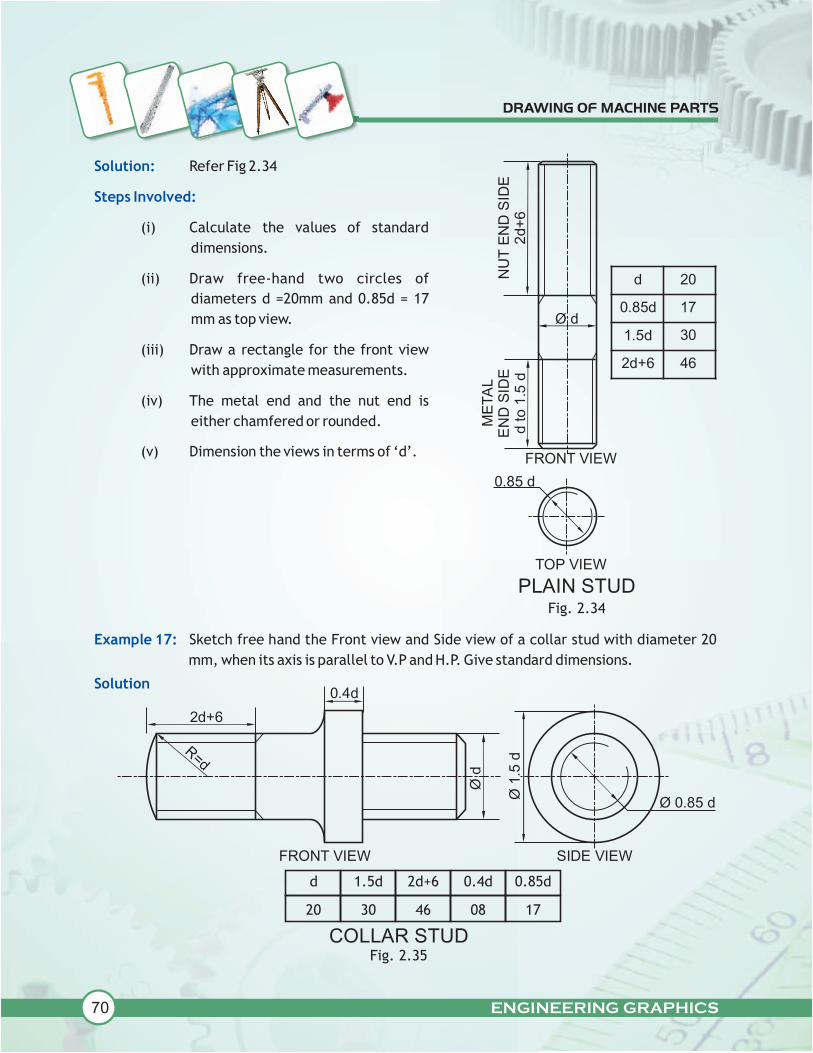
Example 16: Sketch freehand the Front view and Top view of a Plain stud of diameter
= 20mm, keeping its axis vertical.
Fig 2.32
ENGINEERING GRAPHICS
Solution:
Steps Involved:
Refer Fig 2.34
(i) Calculate the values of standard
dimensions.
(ii) Draw free-hand two circles of
diameters d =20mm and 0.85d = 17
mm as top view.
(iii) Draw a rectangle for the front view
with approximate measurements.
(iv) The metal end and the nut end is
either chamfered or rounded.
(v) Dimension the views in terms of ‘d’.
Example 17:
Solution
Sketch free hand the Front view and Side view of a collar stud with diameter 20
mm, when its axis is parallel to V.P and H.P. Give standard dimensions.
Fig. 2.35
Fig. 2.34
d
20
1.5d
30
2d+6
46
0.4d
08
0.85d
17
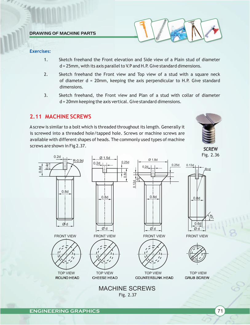
ENGINEERING GRAPHICS
Exercises:
1. Sketch freehand the Front elevation and Side view of a Plain stud of diameter
d = 25mm, with its axis parallel to V.P and H.P. Give standard dimensions.
2. Sketch freehand the Front view and Top view of a stud with a square neck
of diameter d = 20mm, keeping the axis perpendicular to H.P. Give standard
dimensions.
3. Sketch freehand, the Front view and Plan of a stud with collar of diameter
d = 20mm keeping the axis vertical. Give standard dimensions.
A screw is similar to a bolt which is threaded throughout its length. Generally it
is screwed into a threaded hole/tapped hole. Screws or machine screws are
available with different shapes of heads. The commonly used types of machine
screws are shown in Fig 2.37.
2.11 MACHINE SCREWS
Fig. 2.36SCREW
Fig. 2.37

ENGINEERING GRAPHICS
Example 18:
Solution:
Sketch freehand the front view and top view of a cheese head screw of size M2O,
keeping its axis vertical. Give standard dimensions.
Refer Fig. 2.38
CHEESE HEAD SCREWFig. 2.38
d 20
0.2d
0.85d
04
17
0.25d
0.8d
05
16
1.5d 30

ENGINEERING GRAPHICS
Example 21:
Solution:
Sketch freehand the front view and top view of a 90 flat counter sunk machine
screw of size M20, keeping its axis vertical. Give standard dimensions.
Refer Fig. 2.39
d 20
0.2d 4
0.25d 5
d/8 2.5
0.85d 17
1.8d 36
Fig. 2.39
Exercises
1. Sketch freehand the Front view and Side view of a round head screw of size M10,
keeping its axis horizontal. Give standard dimensions.
2. Sketch freehand the Front view and Side view of cheese head machine screw of
size M10, keeping its axis horizontal and parallel to V.P. and H.P. Give standard
dimensions.
3. Sketch freehand the Front view and Top view of a 90 degree flat counter sunk
machine screw of size M10, keeping its axis vertical. Give standard dimensions.
4. Sketch freehand the Front view and Side view of a hexagonal socket head machine
screw of size M20, keeping its axis parallel to V.P and H.P. Give standard
dimensions.
5. Sketch freehand the Front view and Top view of a grub screw of size M10, keeping
its axis vertical. Give standard dimensions.

ENGINEERING GRAPHICS
2.12 RIVETSAND RIVETED JOINTS.
We are familiar with riveted joints with our kitchen
wares likes pressure cooker and frying pan. In
pressure cooker, the handle is joined to the body by
means of rivets. We can even notice the rivets fitted,
in shoes, belts etc.
Rivets are one of the permanent fasteners and is
used widely in steel structures. Rivets are used in
bridges, boilers and other engineering works. A rivet
is a simple round rod having head at its one end (see
Fig. 2.40 (i) and the other end is made in the form of
head when it is assembled to fasten the parts.
Rivet heads are of many shapes.
RIVETFig. 2.40 (i)
2.12.1 TYPES OF RIVETS
Fig. 2.41 shows views of some of the types of rivets given in our syllabus.
Fig. 2.41
Fig. 2.40 (ii)

ENGINEERING GRAPHICS
Fig. 2.42
d 20
0.7d 14
0.8d
1.6d 32
16
Example 24:
Solution:
Sketch freehand the front view and top view of a pan head rivet of diameter
20mm, keeping its axis vertical. Give standard dimensions.
Refer Fig 2.43
Fig. 2.43
d 20
0.7d 14
1.6d 32
Example 23:
Solution:
Sketch freehand the Front view and Top view of a snap head rivet of diameter
20mm, keeping its axis vertical. Give standard dimensions.
Refer Fig 2.42

ENGINEERING GRAPHICS
EXERCISES
1. Sketch freehand the Front view and Top view of a snap head rivet of diameter
25mm, keeping its axis vertical. Give standard dimensions.
2. Sketch freehand the Front elevation and Plan of a pan head rivet of diameter
25mm, keeping its axis vertical. Give standard dimensions.
3. Sketch freehand the Front view and Top view of a 60° counter sunk flat head rivet
of diameter 20mm, keeping its axis vertical. Give standard dimensions.
4. Sketch freehand the Front view and Top view of a flat head rivet of diameter
20mm, keeping its axis vertical. Give standard dimensions.
2.12.2 RIVETED JOINTS
ORTHOGRAPHIC VIEWS OF SINGLE RIVETED LAP JOINT
Example 17:
Riveted joints are of two types namely
(i) Lap joint
(ii) Butt joint
Lap joints may be single, double and multiple riveted. In class XII, we are going to study the views
of "single" riveted lap joint.
In single riveted lap joint, the plates to be joined together overlap each other and "a single
row of rivets" passes through both the plates.
Fig. 2.44
Let us now learn how to draw the views of single riveted lap joint.
Draw to scale 1:1, the top view and sectional front view of single riveted lap joint,
when the thickness of the plates to be joined = 16mm.

ENGINEERING GRAPHICS
Fig. 2.44
Solution: Refer Fig. 2.44
Steps Involved:
Before starting the view, the standard dimensions are to be calculated as follows.
Let't' be the thickness of the plates to be be joined. Here t =16mm
The empirical formula for calculating the diameter'd' of the rivet to be used is given as
d = 6t = 24mm.
The margin 'm' is "the distance from the centre of the rivet to the nearest edge of the
plate", and is taken as m = 1.5d = 36 mm.
The pitch 'p' is the distance between the centres of the adjacent rivets, and is taken as
P = 3d = 72 mm
The angle 10 degree is made by the fullering tool (a special punch or chisel) to make the
joint leak proof. (The process of fullering is beyond the scope of this book.)
Then the top view and the sectional front view are to be done as shown clearly in Fig 2.44.
The edges of the plates in the top view are shown in wavy lines to represent a part of
plates.

ENGINEERING GRAPHICS
Exercises :
1. Draw to scale full size, the full sectional front view of a single riveted lap joint,
taking thickness of the plates as 9mm. Give standard dimensions.
2. Draw to scale 1:1, the front view in section and plan of a single riveted lap joint,
taking the thickness of the plates as 25mm. Give standard dimensions.
2.13 KEYS
Key is piece of metal which is used to fasten two parts together, specially to join two circular parts
together. For example, pulleys, flywheels etc. are joined to the shaft by means of a key. Key is one
of the temporary fasteners as it can be removed easily whenever required. The groove cut on the
shaft to accommodate a key is called key seat and the corresponding groove in the matting piece
is called key way.
Fig. 2.45
2.13.1 TYPES OF SUNK KEYS
Sunk key means, half of the thickness (0.5T) (measured at the side not on centre line)
lies within the key seat and the other half thickness (0.5T) lies within the keyway (see
Fig 2.46 (a).Asunk key is designated by its width X thickness X length (W X T X L). There are
different types of sunk keys viz.
(i) rectangular taper key
(ii) woodruff key
(iii) double head feather key
Let us now learn how to draw the views of these sunk keys.

ENGINEERING GRAPHICS
2.13.1.1 RECTANGULAR TAPER KEY
Rectangular sunk taper key is of rectangular cross section, with the thickness not uniform
throughout the length of the key. See Fig 2.46
RECTANGULAR TAPER KEY (IN POSITION)Fig. 2.46 (a)
Fig. 2.46 (b)
Example :
Sketch freehand the front view, side view and top view of a rectangular taper key for a
shaft of diameter 40mm. Give standard dimension.
Fig. 2.47

ENGINEERING GRAPHICS
Drawing proportions for a rectangular taper key are as follows.
Let 'D' be the diameter of the shaft, then width of the key, W=D/4
Thickness of the key, T=D/6
Length=1.5D to 2D, Taper = 1 in 100
The taper key prevent relative rotational as well as axial movement between the two
mating pieces. Generally, the upper surface of the key is tapered and hence the keyway is
also correspondingly tapered. The tapered end is hammered to remove the key from the
joint.
2.13.1.2 WOODRUFF KEY
Woodruff key is a special sunk key. It looks like a segment of a circular disc. The key seat is
semi circular in shape but the keyway is rectangular. The keyway is smaller in size than the
key seat. The advantage of woodruff key is that it can be easily adjusted in the recess. It is
largely used in machine tools and automobile works.
Fig. 2.48 (a)
Fig. 2.48 (b)

ENGINEERING GRAPHICS
Example 26:
Solution:
Sketch freehand the Front view, Top view and Side view of a woodruff key, suitable
for a shaft of diameter 40mm. Give standard dimensions.
Refer Fig 2.49
Fig. 2.48 (c)
40
D
6.7 13.4 10
0.25TT =D6
R = 2T
Fig. 2.49

ENGINEERING GRAPHICS
2.13.1.3 DOUBLE HEAD FEATHER KEY WITH GIB HEAD ON BOTH ENDS
Feather key is a kind of sunk parallel key.
In a parallel key, the thickness remains
same throughout the length of the key. Fig
2.51 shows a feather key with gib head. A
double head feather key with gib head on
both ends grips the hub between its
heads. Fig. 2.50
Fig. 2.51 (b)
Fig. 2.51 (1)

ENGINEERING GRAPHICS
Exercises:
1. Sketch freehand the Front view, Side view and Plan of a rectangular taper key for a
shaft of diameter 60mm. Give standard dimensions.
2. Sketch freehand the Front view, Side view and Plan of a woodruff key for a shaft of
60mm diameter. Give standard dimensions.
3. Sketch freehand the Front view, Top view and Side view of a double head gib key
for a shaft of 40 mm diameter. Give standard dimensions.
D 60
15
10
W
T
1.5T
1.75T 17.5
15
Fig. 2.52
Example 28:
Solution:
Sketch freehand the front view, side view and plan of a double-head gib key for a
shaft of diameter 60mm. Give standard dimensions.
Refer Fig 2.52
3.1 INTRODUCTION
3.2 JOURNAL BEARINGS
All of you have seen a bicycle and most of you may know how to ride it. Do you know how a
bicycle runs so smoothly and easily? The reason is that friction is greatly reduced by using
bearings in the moving parts and you must have oiled/ greased these bearings from time to time.
In the industry also, the bearings are used to help in smooth running of the shafts. There shaft is
a rotating circular rod and which is used to transmit power from one machine to another.
So a shaft bearing is a mechanical component used to support or guide a shaft and allow
rotational or sliding motion between two or more machine parts. They are widely used in
mechanical and industrial applications including automotive, aerospace, industrial machinery
etc.
These are broadly classified according to the type of motion as:
1. Plain/sliding contact bearings.
2. Anti-Friction bearings/Rolling Bearings.
We will learn about some of the plain/sliding contact bearings. They have a rotating shaft which
has a sliding contact with the bearing which is held stationary. They do best when materials in
contact are dissimilar.
Plain/sliding contact bearings are further classified according to leading conditions as:
1. Journal bearings
2. Thrust bearing
3. Pivot bearing
In this chapter, we shall learn about Journal bearings, where load on the bearing is normal to
the shaft axis. The term ‘journal’ refers to that part of the shaft which is in contact in the
bearing.
Some examples of Journal bearings are:
1. Open bearing
2. Bush bearing
In our syllabus, the assembly and Dis-assembly of such machines are prescribed.
As machines have more than one or numerous components, these components need to be fit in
proper position or assembled.
3
ENGINEERING GRAPHICS

Similarly, to understand & manufacture each individual machine part, the machine has to be
disassembled. So let us learn about assembly & dis-assembly with respect to the machines we
study.
This type of journal bearing consists of a ‘U’ shaped cast iron body with a similar shaped
collared brass, bronze or gun-metal bush. The bush can be replaced with a new one when worn
out. The base plate or sole in the body is recessed leaving a standing material all around, known
as padding which helps in the stability of the sole on the resting surface and also reduces the
machining area. Usually elongated drilled holes are provided in the sole plate to facilitate any
misalignment or lateral adjustments of bolts while fitting the bearing in position on base/floor.
This bearing is used for linear and zigzag shafts, which rotate at slow speeds. Now let us
understand the different parts shown in Fig. 3.1
3.2.1 OPEN BEARING
ENGINEERING GRAPHICS
Example:
The figure given below (Fig:3.2) shows the details of an 'Open bearing'. Assemble these
parts correctly and then draw its following views to scale1 :1
a. Front view, right half in section.
b. Top view.
Write heading and scale used. Draw projection symbol. Give '6' important dimensions.
Fig. 3.1

ENGINEERING GRAPHICS
Fig: 3.2
Fig: 3.3
Solution:

ENGINEERING GRAPHICS
Exercise:
The given figure shows the details of the parts of an OPEN BEARING. Assemble these parts
correctly, and then draw the following views to scale 1:1
(a) Front view, left half in section
(b) Left Side view
Print the titles and scale used. Draw the symbol of projection. Give six important dimension.
Fig: 3.4

Example :
The figure given below (fig 3.12) shows the assembly of an 'Open Bearing'. Disassemble the
parts and draw the following views to scale 1:1 :
(a) BODY
(i) Front view, left half in section.
(ii) Top view, without section.
(b) BUSH
(i) Front view, left half in section.
(ii) Side view, viewing from left.
Print titles of both and the scale used. Draw the projection symbol. Give '6' important
dimensions.
ENGINEERING GRAPHICS
Example :
The figure given below shows the assembly of an ‘Open Bearing’. Dis assemble the parts
correctly and then draw the following views of the following parts to scale 1:1, keeping the
same position of Body and Bush, with respect to V.P. and H.P.
(a) Body
(i) Front view left half in section
(ii) Top view
(b) Bush
(i) Front view left half in section
(ii) Left side view
Print titles and the scale used. Draw the projection symbol. Give six important dimensions.
Fig. 3.5

ENGINEERING GRAPHICS
Solution:
Fig. 3.6

ENGINEERING GRAPHICS
Exercise:
The figure given below shows the assembly of an OPEN BEARING. Disassemble the parts and
then draw the following views of the following parts to scale 1:1, keeping the same position
of both the Base and the Bush, with respect to H.P. and V.P.
(a) BASE
(i) Front view, showing left half in section
(ii) Top view
(b) BUSH
(i) Front view, showing right half in section
(ii) Top view
Print titles and the scale used. Draw the projection symbol. Give six important dimensions.
Fig. 3.7
FRONT VIEW SIDE VIEW

ENGINEERING GRAPHICS
3.2.2 BUSH BEARING
It is a journal bearing in which the bush is made of some soft material such as brass, bronze
or gun metal. This bearing is useful for higher loads at medium speed. The bush is tightly
fitted into a bored hole in the body of the bearing. The inside of the bushes is bored as a fit
for the shaft. The sole is recessed for better stability on the surface.
A counter sunk hole is drilled at the top of the body to pour the lubricant which helps to
reduce friction between the shaft and bush. The holes for the bolts in the sole plate are
elongated towards the width. This bearing is generally placed only at or near the ends of the
shaft, as the shaft can be inserted end wise only.
Fig. 3.8

ENGINEERING GRAPHICS
Example :
The figure given below shows the details of the parts of a Bush Bearing. Assemble these parts
correctly and then draw its following views to a scale 1:1
a. Front view, right half in section
b. Top view
Print titles and the scale used. Draw the projection symbol. Give six important dimensions.
Fig. 3.9

ENGINEERING GRAPHICS
Solution :
Fig. 3.10

ENGINEERING GRAPHICS
Exercise :
The given figure shows the details of the parts of a BUSH BEARING. Assemble these parts
correctly, and then draw to scale 1:1, the following views.
(a) Front view, left half in section
(b) Right side view
Print titles and the scale used. Draw the projection symbol. Give six important dimensions.
Fig. 3.11

ENGINEERING GRAPHICS
Example :
The figure given below shows the assembled front view and the side view of a Bush Bearing.
Disassemble the body and the bush and draw the following views to a scale 1:1, keeping the same
position of both the body and the bush, with respect to H.P. and V.P.
a. BODY – Front view, showing right half in section and its Top view.
b. BUSH – Front view, showing left half in section and its Top view.
c. Print titles of both and scale used. Draw the projection symbol. Give 8 important dimensions.
Note : Take R4 Radius forAll FilletsAnd Rounds.
Fig. 3.12

ENGINEERING GRAPHICS
Solution :
Fig. 3.13

ENGINEERING GRAPHICS
Exercise :
The figure given below shows the front view and side view of the assembly of Bush Bearing.
Disassemble the parts and draw the views of the following parts to scale 1:1. Keep the same
position of the parts with respect to H.P. and V.P.
(a) BODY
(i) Front view, left half in section
(i) Side view
(b) BUSH
(i) Front view, right half in section
(ii) Top view
Print titles and the scale used. Draw the projection symbol. Give six important dimensions.
Fig. 3.14

4.1 INTRODUCTION
All of you have seen a tractor and its trolley/ trailer. The trolley can be easily joined or removed
from the tractor as per the need. Have you ever noticed that how this trolley is joined or detached
from the tractor? This work is made so simple by a joint between the tractor and the trolley using
a pin or a cotter. There is a fork end at the back of the tractor and an eye end in front of the
trolley. A round pin is inserted in between these two to make the joint. In industry also different
rod joints are used, some of these we shall learn in the following paragraphs. But first we shall
learn about the cotter.
4
4.2 COTTER
4.3 COTTER JOINT
A cotter is a temporary fastener which is used to connect rigidly two rods, whose axes are
collinear and subjected to axial forces only. It is a wedge shaped piece of mild steel block which is
uniform in thickness but tapered in width. The tapering is done on one side of the cotter and is
usually 1 in 30. The taper on the cotter helps in insertion into the position and its withdrawal. It
also helps in the lateral adjustment of the connected parts.
A joint in which cotter is used to lock two rods together is called cotter joint. Here, we shall study
about cotter joints for joining two round rods viz.
(a) Sleeve and cotter joint (using two cotters)
(b) Socket and spigot joint (using one cotter)
We shall also study about a cotter joint for joining two square rods viz.
(c) Gib and cotter joint (using one gib and one cotter)
ENGINEERING GRAPHICS
Fig 4.1 (a) Use of Rod Joint Fig 4.1 (b) Cotter

ENGINEERING GRAPHICS
4.3.1 SLEEVEAND COTTER JOINT:
Sleeve and cotter joint is used to connect two round rods. The rods are forged and increased in
diameter to some length just to compensate for the loss of material for making rectangular hole
to accommodate the rectangular tapered cotter in each rod. The ends of both the rods are
chamfered to avoid burring and easy insertion in the hollow steel sleeve (socket/cylinder/muff).
Both the rods are of the same dimensions.Ahollow sleeve is passed over both the rods and has two
rectangular holes for the insertion of cotter at right angle to the axes of the rods. The cotters are
automatically adjusted due to the extra margin given for the clearance in the rod and the sleeve.
The relative position of slots is such that the driving in of the cotters tends to force the rods
towards each other in the socket or hollow sleeve. When sleeve and rods are subjected to axial
tensile force the cotter is subjected to shearing force. These joints are useful for light
transmission of axial loads.

ENGINEERING GRAPHICS
Example:
Figure given below (Fig : 4.3) shows the parts of a Sleeve and Cotter Joint. Assemble these parts
correctly and then draw the following views to scale 1 : 1.
(a) Front view, upper half in section.
(b) Side view, viewing from the left.
Print title and scale used. Draw the projection symbol. Give '8' important dimensions.
Fig 4.3
Solution:
Fig: 4.4

ENGINEERING GRAPHICS
Exercise:
The given figure shows the details of parts of a sleeve and cotter joint. Assemble these parts
correctly and then draw the following views to scale 1:1.
(a) Front view lower half in section
(b) Left side view
Fig 4.5

Example:
The figure given below shows the assembly of a Sleeve and Cotter Joint. Disassemble thefollowing parts and draw the following views to a full size scale.
(a) Sectional front view of the Sleeve and Side viewviewing from left.
(b) Front view of RodAand Side view viewing from left.
(c) Front view of Cotter B in vertical position and Top view.
Print titles and scale used. Draw the projection symbol. Give 8 important dimensions.
ENGINEERING GRAPHICS
Solution :
Fig 4.7
Fig 4.6

ENGINEERING GRAPHICS
Exercise:
The figure given below shows the assembly of a Sleeve and Cotter joint. Disassemble the parts
and draw the following views of the following parts, to scale 1:1. Keep the position of the parts
same with respect to V.P. and H.P.
(a) SLEEVE
(i) Front view, upper half in section
(ii) Side view, looking from left
(b) COTTER B
(i) Front view
(ii) Side view
Fig 4.8

ENGINEERING GRAPHICS
Exercise:
The figure given below shows the assembly of a Sleeve and Cotter joint. Disassemble the parts
and draw the following views of the following parts, to scale 1:1. Keep the position of the parts
same with respect to V.P. and H.P.
(a) SLEEVE
(i) Front view, lower half in section
(ii) Side view, looking from right
(b) RODA
(i) Front view
(ii) Side view looking from right

ENGINEERING GRAPHICS
4.3.2 SOCKETAND SPIGOT JOINT
Socket and Spigot Cotter Joint connects two rods in such a way that it can transfer axial
compression or tensile load. In this case one end of the first rod is enlarged in diameter to some
length, just to compensate the loss of material due to rectangular hole made in it to
accommodate a cotter.Acollar is provided at the end of the enlarged end. This is known as spigot.
One end of the second rod is formed into a socket or box having an appropriate inner diameter to
fit the spigot along with a collar. For simplicity socket can be considered as a hollow pipe having
one side solid and the other hollow, while the spigot is a solid rod. The solid spigot is nearly of the
size of the internal radii of the socket, where it can fit. They have a rectangular cavity of tapering
construction through both the parts, i.e., spigot and socket where the cotter is inserted. This
cavity or slot is kept slightly out of alignment so that driving in of the cotter tends to pull the slots
in a line, thus making the joint perfectly tight and rigid. A clearance of 2 to 3 mm is made in these
joints for the proper functioning of the cotter.
Fig 4.10

Example:
The details of a Socket and Spigot joint are shown below.Assemble these parts correctly and then
draw its following views to scale full size.
(a) Front view upper half in section.
(b) Side view, as viewed from right.
Print heading and scale used. Draw projection symbol. Give six important dimensions
Fig 4.11
ENGINEERING GRAPHICS

Solution:
ENGINEERING GRAPHICS
Exercise:
The given figure shows the details of parts of a SPIGOT AND SOCKET JOINT. Assemble these
parts correctly, and then draw the following views to scale 1:1
(a) Front view, lower half in section
(b) Right side view
Fig 4.12

Example:
The following figure shows the assembly of a Socket and Spigot Cotter Joint. Disassemble the
following parts and draw the following views to a full size scale.
SOCKET
(a) Front view upper half in section
(b) Left side view
ENGINEERING GRAPHICS

ENGINEERING GRAPHICS
COTTER
(a) Front view
(b) Right side view

ENGINEERING GRAPHICS

Exercise:
The figure given below shows the assembly of Socket and Spigot joint. Dis assemble the parts and
draw the views of the following parts to scale 1:1. Keep the same position of the parts with
respect to H.P. and V.P.
(a) SOCKET
(i) Front view, lower half in section
(ii) Side view, looking from left.
(b) SPIGOT
(i) Front view, upper half in section
(b) Side view, looking from right.
ENGINEERING GRAPHICS

Exercise:
The following views of a Socket and Spigot Joint are given. Disassemble the parts as given below
and draw the following views :
(a) SPIGOT
(i) Front view lower half in section.
(ii) Side view from left.
(b) SOCKET
(i) Front view upper half in section
(ii) Right side view.
Print headings and scale used. Draw projection symbol. Give 8 important dimensions
ENGINEERING GRAPHICS
Fig 4.17

4.3.3 GIBAND COTTER JOINT
This joint is used to join two rods of square or rectangular in cross section. The end of one rod is
forged in the form of a fork or strap. The height of the other rod is increased for compensating the
loss of material in making the slot for cotter. The Gib is made up of mild steel and has the same
thickness as that of the cotter. The Gib has projections at the top and bottom ends which act like
hooks. While connecting two rods the Gib is inserted first and pushed towards the end of the fork
and then the cotter is hammered over. The tapering sides of the Gib and the cotter mate with
each other, while their outer sides are parallel to each other and perpendicular to the common
axis of the rods. Hence, when a Gib is used with a cotter, the opposite faces of the slots in the rods
are parallel to each other. The Gib increases the tearing area of the cotter and prevents
slackening of the joint besides holding the jaws of the strap or fork from opening wide when the
cotter is inserted. The use of Gib and Cotter enables the parallel holes to be used. Here Gib and
Cotter both have taper on one edge. This joint is useful to fasten connecting rods of a steam
engine or marine engine.
Fig. 4.18 (b)
Fig. 4.18 (a)
ENGINEERING GRAPHICS

Example:
The figure given below shows the detail drawings of different parts of a Gib and Cotter Joint for
joining two square rods.Assemble all the parts correctly and draw the following views to scale 1:1
(a) Front view, upper half in section.
(b) Side view, viewing from the left hand side.
(c) Print title, scale used and draw the projection symbol. Give '6' important
dimensions.
ENGINEERING GRAPHICS
Fig 4.19

ENGINEERING GRAPHICS
Solution:
Fig
.4.2
0

ENGINEERING GRAPHICS
Exercise:
The figure given below shows the detail drawings of different parts of a Gib and Cotter Joint for
joining two square rods.Assemble all the parts correctly and draw the following views to scale 1:1
(a) Front view, lower half in section.
(b) Side view, viewing from the left hand side.
(c) Print title, scale used and draw the projection symbol. Give '6' important
dimensions.
Fig 4.21

ENGINEERING GRAPHICS
Example:
The figure given below shows the assembly of a Gib and Cotter joint. Disassemble the following
parts and draw the following views to a full size scale.
(i) STRAP (FORK)
(a) Front view lower half in section
(b) Top view
(ii) GIB
(a) Front view
(b) Top view

ENGINEERING GRAPHICS
Solution:

ENGINEERING GRAPHICS
Exercise:
The figure shows the front view of the assembly of a Gib and Cotter Joint for square rods. Dis
assemble the parts and then draw the following views of the following parts to scale 1:1,
keeping the parts in the same position, with respect to H.P. and V.P.
(1) STRAP (FORK)
(i) Upper half sectional front view
(ii) Top view
(2) GIB
(i) Front view
(ii) Top view
Print title, scale used and draw the projection symbol. Give '6' important dimensions.

Exercise:
The orthographic views of a Gib and Cotter Joint assembly are given below. Disassemble the parts
and draw the following views of the following parts to scale 1:1, keeping the parts in the same
position with respect to H.P. and V.P.
(a) FORK END
(i) Front view lower half in section (ii) Top view
(b) EYE END
(i) Front view lower half in section (ii) Top view
(c) GIB
(i) Front view (ii) Top view
(d) COTTER
(i) Front view (ii) Top view.
Print headings of the above views and scale used. Draw projection symbol. Give six important
dimensions.
ENGINEERING GRAPHICS
Fig 4.25

5.1 INTRODUCTION
5.2 TIE-ROD JOINT/TURNBUCKLE
Machines use various parts which are joined in several ways for the machine to function as a
whole. We have learnt about some devices like fasteners (temporary & permanent) and some
simple joints to join two rods in the previous chapters. Let us now learn some more miscellaneous
joints which are commonly used, viz.
(a) TIE-ROD JOINT/TURNBUCKLE
(b) FLANGE PIPE JOINT
In our day to day life, we may come across
rods/machine parts which are subjected to push
and pull and this joints need to be tightened or
loosened as in the case of wires of electric poles,
cables, a sailboat's standing, rigging wires or
even in boxing rings.
In such cases, an adjustable joint known as
'turnbuckle' is used. Turnbuckle/Tie-rod Joint is
an adjustable temporary joint, which connects
the ends of two rods axially when they are subjected to push/pull (tensile) forces. It serves as a
joining device between the ropes and the posts or rods.
5
(a) Commercial Type Turnbuckle.
(c) In boxing rings
Fig.5.1
(b) In electric poles.
ENGINEERING GRAPHICS

The 'turnbuckle' consists of an elongated metal tube (body) which is cylindrical in shape and has
tapered ends. Its central portion has a slot to aid tightening and loosening of rods by tomy bar.
Each tapered end of the body has threaded holes with opposite internal screw threads, i.e. right
hand (RH) threads at one end and left-hand (LH) threads at the other, as shown in Fig 5.2.
Fig. 5.2
(We have discussed about the right hand and left hand screw threads (RH & LH) in Chapter 2).
Even the two rods / ring bolts have threads of opposite hand, which are screwed in and out of the
body simultaneously to adjust the pull/ push (tension) or length, without twisting the wires or
attached cables.
Fig. 5.3
ENGINEERING GRAPHICS

Now, let us understand their orthographic views, with the help of an example and move on to
assembly of different parts of the `Turnbuckle' and then drawing of the required sectional views.
The Fig 5.4 shows details of the parts of a Turnbuckle. Assemble these parts
correctly and then draw its following views to scale 1:1, inserting 50mm
threaded portion of each rod inside the body of Turnbuckle.
(a) Front view, upper half in section.
(b) Top view.
(c) Side view as viewed from left.
Write heading and scale used. Draw projection symbol. Give important
dimensions.
Example :
Fig. 5.4
ENGINEERING GRAPHICS

ENGINEERING GRAPHICS
Solution:
Points to remember :
(1) Only 50mm of the threaded portion of the rods will be inside the turnbuckle, the
remaining 30mm portion will be shown outside the body as can be seen in the
Fig. 5.5 below.
(2) It can also be noticed that the width of the edges of the slots can be obtained
from the side view.
(3) In the sectional front view, the rods need not be locally sectioned as no intricate
inner details are present, as in the previous chapter.
Let us consider another example, and draw the orthographic views of the assembled
parts.
The Fig 5.6 shows the details of the parts of a Turnbuckle. Assemble these parts
correctly, and then draw its following views to scale 1:1, inserting 60mm
threaded portion of each rod inside the body of the Turnbuckle.
(a) Front view, lower half in section.
(b) Side- viewas viewed from the right.
Print title and scale used. Draw projection symbol. Give six important
dimensions.
Example :
Fig. 5.5

ENGINEERING GRAPHICS
ASSEMBLED ORTHOGRAPHIC VIEWS OF A TURNBUCKLEFig. 5.7
Solution:
Fig. 5.6

ENGINEERING GRAPHICS
Exercise:
The given figure shows the details of the parts of a Turnbuckle.Assemble these parts correctly and
then draw the following views using scale 1:1, inserting 55 mm threaded position of each rod
inside the body of the turnbuckle.
(a) Front view, upper half in section
(b) Left hand side view.
Fig. 5.8

ENGINEERING GRAPHICS
Exercise :
Figure 5.9 and shows the disassembled views of the parts of a Turn Buckle. Assemble the parts
correctly, and then draw the following views to scale 1:1, inserting 50 mm threaded portion of
each rod inside the body of the Turn Buckle.
(a) Lower half sectional elevation.
(b) Plan.
Print the title and scale used. Give six important dimensions.
FRONT VIEW UPPER HALF IN SECTION
(a) BODY
Fig.5.9

ENGINEERING GRAPHICS
Example:
The given figure shows the assembly of parts of a TURNBUCKLE. Dis-assemble the parts and then
draw the following views of the following components to scale 1:1, keeping them in the same
position with respect to H.P. and V.P.
(a) BODY
(i) Front view, lower half in section
(ii) Top view
(b) ROD-B
(i) Front view
(ii) Left hand side view

ENGINEERING GRAPHICS
Solution:

ENGINEERING GRAPHICS
Exercise :
The given figure shows the assembly of a Turn Buckle. Disassemble the parts and then draw the
following views, to scale 1:1, keeping the same position of the parts with respect to H.P. and V.P.
(a) BODY
(i) Front view upper half in section
(ii) Top view
(b) ROD B
(i) Front view
(ii) Left side view

ENGINEERING GRAPHICS
5.3 PIPE-JOINTS
Those long hollow cylinders or 'pipes' are a regular feature, be it the pipes that bring water from
treatment plants to your home or the drainage pipes or even the roadside long gas pipe-line.
Fig. 5.13 (b)
Since ages, we know pipes have been extensively used as carriers of fluids like water, oil, steam
gas, waste, for water supply systems, oil refineries, chemical plants, sewage piping system etc.
And these pipes may be made of different materials like cast-iron, steel, wrought iron, plastic or
concrete as per the requirement; but they "can't be made of a desired length" for a particular use,
due to constraints of manufacturing, transportation, storing and handling difficulties. So pipes of
standard length are taken and joined together, depending upon the material and purpose for
which it is used.
The most common among them is the 'Cast Iron Flange Pipe Joint' which we will discuss in detail.
As the name suggests, this type of joint is used for cast-iron (C.I.) pipes, which are usually of large
diameter not less then 50 mm and used mostly for low-pressure applications, such as underground
sewer pipes, water and gas lines and drainage in buildings. We can also see this type of joint in the
water outlet pipes installed in several schools as a fire safety measure.
In this type of joint, both the hollow cylindrical pipes have a projected circular ring/ flared rim on
their ends, which is known as 'flange', as shown in fig 5.14. It serves to hold the pipe in place, give
it strength and also attach to another flange. The flanges are made thicker than the pipe-walls for
strength. Greater strength may be required when pressure is high; so the thickness of the pipe-
walls is increased for short lengths in steps, as indicated in the fig 5.14. We also know pipes carry
liquids and gases and they need to be tight and leak-proof. In order to do so, a mechanism similar
Fig. 5.13 (a)

ENGINEERING GRAPHICS
to the one, we use in pressure cookers is utilized i.e., here also we have a similar thin circular
packing ring/gasket of soft material, such as Indian rubber, canvas etc. coated with red lead. This
is placed in between the faces of the two flanges. For perfect alignment, these faces are
machined at right angle to the axes of the pipes. Then these flanges with the gasket in between
are connected together by means of nuts and bolts which are fitted through the holes in the
flanges. (The bolts and nuts may be square-headed or hexagonal-headed in shape.)
Thus, it can be seen that flange joints help in easy and fast disassembly to withstand higher
pressures.
Fig. 5.14

ENGINEERING GRAPHICS
Let us now understand the orthographic views of different parts of the Flange Pipe Joint and learn
to assemble them correctly. And then draw the sectional view & other orthographic views of the
assembly.
Figure 5.16 shows the details of the parts of a Flanged Pipe Joint. Assemble these parts correctly
and then draw to scale 1:1, its following views:
(a) Front view, upper half in section.
(b) Side view, as viewed from left.
Write heading and scale used. Draw projection symbol. Give six important dimensions
Example :
Fig. 5.15

ENGINEERING GRAPHICS
Fig. 5.16

ENGINEERING GRAPHICS
Let us consider another example, to understand the assembled views correctly.
Fig 5.18 shows the details of a Flange Pipe Joint. Assemble these parts correctly, and then draw
the following views to a scale full size:
(a) Front view, showing bottom half in section
(b) Side view as seen, from the right.
Print title and scale used. Draw the projection symbol. Give important dimensions.
Example :
Fig. 5.17
Solution:

ENGINEERING GRAPHICS
Fig. 5.19
Solution:
Fig. 5.18

ENGINEERING GRAPHICS
Exercise :
The given figure shows the details of parts of Flange Pipe joint. Assemble these parts and draw to
scale 1:1, the following views of the assembly.
(a) Front view lower half in section
(b) Left side view
Fig. 5.20

ENGINEERING GRAPHICS
Fig. 5.21
Exercise :
Figure 5.19 shows the details of parts of the Flange Pipe Joint.Assemble these parts correctly and
then draw the following views to full-size scale:
(a) Upper half sectional front view
(b) Left-hand side view.
Print title and the scale used. Draw the projection symbol. Give six important dimensions.

ENGINEERING GRAPHICS
Example :
Figure shows the assembly of parts of a FLANGE PIPE JOINT. Dis-assemble the parts and then draw
the following view of the following components to scale 1:1, keeping them in the same position
with respect to H.P. and V.P.
(a) FLANGE B
(i) Front view, upper half in section
(ii) Right hand side view
(b) GASKET
(i) Full sectional front view
(ii) Left hand side view

ENGINEERING GRAPHICS
Solution :

ENGINEERING GRAPHICS
Exercise :
The given figure shows the assembly of a flange pipe joint. Disassemble the parts and then
draw the following views to scale 1:1, keeping the same position of the parts with respect to
H.P. and V.P.
(a) FLANGE A
(i) Front view top half in section
(ii) Left side view
(b) HEXAGONAL NUT
(i) Front view
(ii) Right side view


ENGINEERING GRAPHICS
Fig. 6.3
To avoid such mishaps, the shape of the flange is slightly modified, which will be discussed further
in the next type of flange coupling.
The faces of the two flanges are then held together with the help of bolts and nuts (4 or more ).
These may be square headed or hexagonal headed. The bolts should be an exact fit, so that the
power can be transmitted properly from one shaft and flange to another.
It can also be noticed, as shown in Fig. 6.3 that the bolt and nuts lie outside, (exposed) and during
rotation of shafts as well as flanges, they are not visible to the workers. This might hurt them or
their clothes may get entangled. Hence this flange coupling get the name as ‘Unprotected Flange
Coupling’.

ENGINEERING GRAPHICS
Example :
Fig 6.4 shows the details of an 'Unprotected Flange Coupling'. Assemble the details and draw the
following views of the assembly using scale full size.
a. Front view, top half in section.
b. Left side view.
Print title and scale used. Draw the projection symbol. Give important dimensions
Fig. 6.4

ENGINEERING GRAPHICS
Solution:
Example :
Fig 6.6 shows the parts of an Unprotected Flange Coupling (having socket and spigot
arrangement). Assemble these parts correctly and then draw the following views to a scale full
size:
a. Front view, upper half in section
b. Side view, as seen from right.
Print title and scale used. Draw the projection symbol. Give important dimensions.
Fig. 6.5

ENGINEERING GRAPHICS
Fig. 6.7
DETAILS OF AN UNPROTECTED FLANGE COUPLINGFig. 6.6
Solution:

ENGINEERING GRAPHICS
Exercise :
Fig 6.8 shows details of an unprotected Flange Coupling. Assemble these parts and draw the
following orthographic views to scale 1:1.
a. Front view, upper half in section
b. Right hand side view, without section.
Show the dimensions properly. Print title and scale used and draw the projection symbol.
Fig. 6.8

ENGINEERING GRAPHICS
Exercise :
The given figure shows the details of the parts of Unprotected Flange Coupling. Assemble these
parts and draw to scale 1:1, the following views of the assembly.
(a) Front view, lower half in section
(b) Right side view
Fig. 6.9
Example :
Figure shows the assembled views of an UNPROTECTED FLANGE COUPLING. Dis-assemble the
parts and then draw the following views of the following parts to full size scale, keeping them in
the same position with respect to H.P. and V.P.
(a) FLANGE-A
(i) Upper half sectional front view
(ii) Right-hand side view
(b) KEY-A
(i) Front view
(ii) Top view
(ii) LH side view

ENGINEERING GRAPHICS
Fig
.6.1
0

ENGINEERING GRAPHICS
Fig. 6.11
Solution:

ENGINEERING GRAPHICS
Exercise :
The figure given below shows the assembly of Unprotected Flange Coupling. Disassemble the
parts correctly and then draw to scale 1:1, the following views of the components, keep the same
position of both FlangeAand hexagonal nut with respect to V.P. and H.P.
(a) FLANGE-A
(i) Front view lower half in section
(ii) Side view, looking from left
(b) HEXAGONALNUT
(i) Front view
(ii) Side view
Fig. 6.12

ENGINEERING GRAPHICS
6.2.2 Protected Flange Coupling
We know, the previous type of flange coupling (Unprotected) has a shortcoming. To over
come it, we need to shield/cover the protruding nuts or bolt heads. And this can be done
by slightly altering the shape of the flanges. So in this type of Flange Coupling the flanges
have a flared and flattened rim i.e. a projected outer ring (shroud) as shown in the figure.
This overhangs over the bolt heads and nuts and minimizes accidents and ensures safety.
Hence it is named as a 'Protected Flange Coupling'.
Fig. 6.13
This type of coupling may be sometimes used as belt pulley.
The ‘Protected type Flange Coupling’ contains the same parts and is assembled in the same way as
an ‘Unprotected type Flange Coupling’. The only difference lies in the shape of the flange with its
projected ring (shroud) as shown in Fig. 6.14.

ENGINEERING GRAPHICS
Fig. 6.14
Fig. 6.15

ENGINEERING GRAPHICS
Example :
Figure 6.16 shows details of the parts of a Protected Flange Coupling. Assemble these parts
correctly and draw the following views to scale full- size:
a. Elevation, Top - half in section
b. End view, as seen from right.
Print title, scale used. Draw the projection symbol. Give main dimensions.
Fig. 6.16

ENGINEERING GRAPHICS
Solution:
Let us assemble the different parts and draw required views in the similar manner as done in the
previous example.
A slight variation is seen in the spigot and socket arrangement. It can be seen that a gap
(Clearance) of 3 mm is present between them as shown in fig 6.17.
Exercise :
1. Fig. 6.18 shows the details of the parts of a ‘Protected Flange Coupling’. Assemble
them correctly and draw the following views to scale 1:1.
a. Lower half - sectional front view
b. Left hand side view
Print the title and scale used. Draw the projection symbol. Give important dimensions.
ASSEMBLY OF A PROTECTED FLANGE COUPLING
Fig. 6.17

ENGINEERING GRAPHICS
Fig
.6.1
8

ENGINEERING GRAPHICS
Example :
Figure shows the assembly of parts of a PROTECTED FLANGE COUPLING. Dis-assemble the parts
and then draw the following views of the following components to scale 1:1, keeping them in the
same position with respect to H.P. and V.P.
(a) FLANGE-A
(i) Front view upper half in section
(ii) Left hand side view
(b) SHAFT-B
(i) Front view
(ii) LH side view
Print titles, scale used. Draw the projection symbol. Give main dimensions.
Ø10
10 8
R4
Ø30

ENGINEERING GRAPHICS

ENGINEERING GRAPHICS
Exercise :
The figure given below shows the orthographic views of the assembly of a Protected Flange
Coupling. Disassemble the parts and then draw the following views of the following parts to scale
1:1, keeping the same positions of both the Flange B and the Shaft B, with respect to V.P. and H.P.
(a) FLANGE-B
(i) Front view, showing upper half in section
(ii) Side view, viewed from the right
(b) SHAFT-B
(i) Front view
(ii) Side view, viewed from the left
Print titles, scale used. Draw the projection symbol. Give main dimensions.

ENGINEERING GRAPHICS
Exercise :
The figure given below shows the assembly of a Protected Flange Coupling. Disassemble the parts
and then draw its views of the the following parts to scale 1:1, keeping the same positions of both
the FlangeAand rectangular sunkTaper Key-Awith respect to H.P. and V.P.
(a) FLANGE-A
(i) Front view, lower half in section
(ii) Side view looking from left
(b) RECTANGULAR SUNK TAPER KEY-A
(i) Front view
(ii) Top view
Print titles, scale used. Draw the projection symbol. Give main dimensions.

ENGINEERING GRAPHICS
7.1 INTRODUCTION
In every machine or toy, we use power to operate and perform its function. This power is obtained
mostly by the motor, run on electricity or battery. To transfer the power from the motor to the
operational part of the machine, we use a combination of pulleys and belt (flexible connector).
Pulleys are used in very small sizes to be fitted in wrist watches and tape recorders, as well as
quite big in size as in ships.
The pulley used, with the motor shaft is called driver and with machine shaft is called driven. The
size of driver and driven pulleys define the ratio of speed transferred as reduced or increased. If
both the driver and driven pulley are of same diameter then the speed of the shaft / spindle will
be same, if driver is of small diameter with respect to driven then the speed will be reduced at
operating shaft and vice versa.
Outer cylindrical surface of the pulley used to
hold the belt is called RIM, while the inner
cylindrical part to be mounted on the shaft is
called HUB. The RIM and the HUB are joined
together with solid web or spokes or splines
depending upon the size of the pulley. In the
pulleys of diameter up to 200 mm a solid web is
provided. The pulley is attached to the shaft
either by the key or by a set screw of the suitable
size and type.
The driver pulley and driven pulley are connected
with different type of endless belts i.e. Flat Belt,
Rope Belt, V-Belt etc. The material of the belt
must be strong in tension yet flexible and
relatively light in weight i.e. canvas, leather,
rubber and so on.
Pulley - drive is very easy to install and require
minimum maintenance. The power is transmitted
from one shaft to another by means of friction
between the belt and the rim. The losses in power
transmission are negligible in V-belt pulley rather
7
Fig. 7.1 (A)
Fig. 7.1 (B)

ENGINEERING GRAPHICS
Pulleys
Type of BeltNo. of
Groove
Flat-Belt
Pulley
Rope
Pulley
Single Groove
Pulley
Double Groove
Pulley
Multiple Groove
Pulley
V-Belt
Pulley
than flat-belt pulley. However power transmission capacity
reaches its limit when the belt starts to slip.
Now we understand that pulleys allow us to
1. Lift loads up, down and sideways.
2. Rotate things at different speeds.
Pulleys are classified as follows :
Fig. 7.1 (C)
So pulley is a simple machine used in our day to day life to complete the work with less efforts. In
this class we will study Flat Belt Pulley, upto 200 mm diameter in detail.
The rim of the flat belt pulley is not flat, it is slightly convex and this is known as the crowning.
Actually the rotating belt around the pulley has a tendency to rise to the highest point of the rim.
In case of a flat rim, there are chances of the slipping off of belt along the side of the pulley. But
the crowning (convex curvature) tends to keep the belt in the middle of the rim.
The pulley is rigidly held to the shaft by key. The keyway is cut with half thickness in hub and half
in shaft. The hub is having thickness to bear the rotational torque of pulley. The out side of the
hub and the inside of the rim are slightly tapered to facilitate the removal of the pattern from the
mould at the time of casting.
7.2 FLAT BELT (SOLID C.I.) PULLEY

ENGINEERING GRAPHICS
(C.I.)
Fig. 7.3
Fig. 7.2

ENGINEERING GRAPHICS
Example :
The figure given below shows the parts of a Solid C.I. Pulley. Assemble them and draw the
following views to scale 1:1
(a) Front View, upper half in section.
(b) Side View.
Write title and scale used. Draw projection symbol. Give '6' important dimensions.
Fig. 7.4

ENGINEERING GRAPHICS
Solution :
Fig. 7.5

ENGINEERING GRAPHICS
Exercise :
The figure given below shows the parts of a Solid C.I. Pulley. Assemble them and draw the
following views to scale 1:1
(a) Front view, lower half in section
(b) Side view, seen from left.
Write title and scale used. Draw projection symbol. Give '6' important dimensions.
Ø14
0
Ø13
0
Ø10
0
Ø20
10
5
10
Ø40
KEYWAY5X2
50
2
Ø10
5
4 HOLES
2

ENGINEERING GRAPHICS
Example :
The figure given below shows the assembly of a Solid Web Cast Iron Pulley. Disassemble the
following parts and draw the following views to a full size scale.
PULLEY
(a) Front view upper half in section
(b) Left side view
SHAFT
(a) Front view
(b) Left side view
Write title and scale used. Draw projection symbol. Give '6' important dimensions.

ENGINEERING GRAPHICS
Exercise :
The given figure shows the assembled view of a Solid C.I. Pulley. Disassemble the parts and draw
the following views to scale 1:1, keeping the same position of the parts, with respect to H.P. and
V.P.
(a) PULLEY
(i) Lower half Sectional front view
(ii) RH Side view
Solution :

ENGINEERING GRAPHICS
(b) KEY
(i) Front view
(ii) Top view
Write title and scale used. Draw projection symbol. Give '6' important dimensions.

FOLLOW THE GIVEN
DIMENSIONS
ONLY
TO DRAW THE FIGURES.