Embed Size (px)
Citation preview

農業 気 象(J.Agr.Met.)42(4):337-347,1987
A Theoretical Investigation of Heat Extraction from a Compost Bed
by Using a Multi-Heat-Pipe Heat Exchanger
Hirakazu SEKI and Tomoaki KOMORI
Department of Civil Engineering, Faculty of Technology,
Kanazawa University, Kanazawa 920
Abstract
A buried-tube-type heat exchanger is typical and simple for extracting heat from a compost bed
except the requirement of some tedious works such as removing and retubing the tubes in remixing the compost materials. In order to simplify the above tedious works, a unique heat extraction method by a multi-heat-pipe heat exchanger was proposed. The analytical solutions of the tempera-
ture in the bed and the temperature of medium at the outlet of the heat exchanger were obtained. These solutions were mathematically similar to those for the buried-tube-type heat exchanger. Then, the heat extraction ability of the multi-heat-pipe heat exchanger was calculated from the solutions.
1. Introduction
A method of extracting the heat generated in a compost bed by water flowing into tubes buried in the bed was presented by Seki and Komori
[1984, 1985a]. In such a buried-tube-type heat exchanger, since the medium fluid was surrounded by the compost materials almost completely, there was no loss of heat in transmission of heat to the
medium fluid through the walls of the buried tubes from the compost bed. Therefore, it was suggested that the buried-tube-type heat exchanger would be available for heat extraction from thecompost bed.
Generally, the composting reactions proceed very slowly and the composting process requiresa long period, moreover, the oxygen stored in the compost bed is consumed successively, so that the rate of heat generation usually decreases gradually with declining the activity of thermophilic aerobic microorganisms due to the oxygen shortage in the bed. Then, to activate the composting reaction
by supplying oxygen, the compost materials mustbe remixed artificially in the composting process. The works, remixing and retubing the tubes for
the medium fluid, for remixing are inconvenientand tedious for the case of the buried-tube-type
heat exchanger. Taking account of convenience
for the above works, Komori et al [1983] proposed another method for heat extraction from the compost bed with a single-heat-pipe heat extractor. For the single-heat-pipe heat extractor, the heat
generated in the compost materials is pumped upto the top of the heat-pipe inserted into the bed, then, the heat is transferred to the medium fluid by convection. The heat-pipe has both functions
of pumping up heat from the bed and of heat exchange.
Since the primitive heat-pipe-type heat ex-changer has only a single element of heat-pipe, it would not be applicable to the practical heat extraction directly, however, the concept of the heat-pipe-type heat exchanger is unique and involves an interest in utilizing a characteristic of
the heat-pipe, which has an excellent heat transfer ability.
In this investigation, for application of the heat-
pipe-type heat exchanger to the practical cases, a multi-heat-pipe heat exchanger is introduced. The
problem of heat extraction from the compost bedby the multi-heat-pipe heat exchanger is solve analytically with suitable boundary conditions,
upon the several assumptions. The calculated results of heat extraction ability for the multi-heat-pipe heat exchanger are compared with those
for the case of the buried-tube-type heat exchanger.
Read at Annual Meeting on 31 May, 1985 Received 15 October, 1986
337

農 業 気 象
2. Mechanism of heat transmission and overall heat transfer coefficient of heat-pipe
The heat-pipe has been applied to many practical engineering fields such as electronic devices, space
ships, stabilization of the permafrost soil andothers [Chi, 1976].
A heat-pipe transfers heat by repeating the
cyclic process of vaporization and condensationof the working fluid sealed in the metalic tubeand it is an excellent heat conductor.
When the bottom portion of a heat-pipe is maintained at higher temperature and the top
portion is kept at lower temperature, the axialtemperature profile of the heat-pipe may be
schematically shown in Fig. 1 [Sun and Tien, 1975]. Heat is rapidly transferred from the
bottom towards the top of the heat-pipe by
vaporizing the working fluid, even though there is
a relatively small temperature difference between
the top and bottom portions.
Supposing that a multi-heat-pipe heat exchanger
is set in the compost bed, as shown in Fig. 2, the
schematic representation of the local temperature
profiles of the compost bed and of the medium fluid contacting with a heat-pipe in the multi-heat-
pipe heat exchanger may be shown as Fig. 3. Theheat generated in the compost bed is conducted
to the bottom portion of the heat-pipe, the heat
input region, through a small gap between the
heat-pipe and compost materials. Therefore, a
temperature at the surface of the heat input region
Te is not equal to the apparent temperature of the compost bed at the interface T|r=r1, exactly.
By introducing a heat transfer coefficient he
corresponding to the heat resistance at the surface
of the heat-pipe, the rate of heat transfer at the
surface of the bottom portion of the heat-pipe is
given by
(1)
The heat conducted to the heat input region of the heat-pipe is rapidly transferred to the top
portion by vaporizing the working fluid. Then, the rate of heat transfer to the axial direction of the heat-pipe is [Komori et al, 1983]
(2)
where Te-Tc is the temperature difference be-Fig. 1 Axial temperature profile of
a heat-pipe
(a) Whole view of an apparatus for heat extraction (b) Details of the water flow pattern in a heat exchanger
Fig. 2 Sketch of a multi-heat-pipe heat exchanger for extraction of heat from the compost bed
338

H. Seki and T. Komori: Heat Extraction from a Compost Bed by a Multi-Heat-Pipe Heat Exchanger
Fig. 3 Schematic representation of the local tem-
perature profiles of the compost bed and of the medium fluid contacting with a heat-pipe
tween the bottom and the top of the heat-pipe and h is an effective heat transfer coefficient of the heat-pipe [Chi, 1976].
The rate of heat transfer to the medium fluid flowing through the heat exchanger is
(3)
where hc is a liquid-film heat transfer coefficient
based on the outer surface of the heat-pipe.
Supposing that the loss of heat in the heat
transmission process of the system is ignored, Q1
is related to Q2 and Q3 as the following equation:
Q1=Q2=Q3. (4)
Accordingly, by using the apparent driving force of temperature T|r=r1-Tl, and by introducing an overall heat transfer coefficient Uh based on
the outer surface of the heat input region, the rate
of heat transfer can be written in a form of
(5)
where Uh is expressed as follows:
(6)
3. Mathematical treatment for the heat
transfer process and analytical solutions
3.1 Differential equations, boundary and initial
conditions governing the heat extraction
process
In the heat extraction process by the multi-heat-
pipe heat exchanger, there are two mechanisms of heat transfer. One is the conduction of heat in a
compost bed and the other is the forced convective heat transfer in the heat exchanger. These mecha-nisms are combined through the heat-pipe, whichis a carrier of heat transport. Therefore, the heat conduction equation for the compost bed and a
heat balance equation for the heat exchanger must be solved simultaneously by using the suitable boundary and initial conditions.
Generally, it is difficult to obtain the exact
analytical solutions for the heat extraction problem of the compost bed. Then, for simplification ofthe problem, the following several assumptions
are made. 1) Conduction of heat in the compost bed
takes place only in the radial direction around the heat-pipe (r-direction).
2) Heat-pipes are arranged in square pitches at
equal spaces, and temperature profiles of the compost around any adjacent heat-pipes are the same.
3) Thermal physical properties of the compost bed are independent of temperature during the heat extraction process.
4) The heat generation term in the conduction
equation is small and ignored, compared with the terms of conduction and accumulation [Seki and Komori, 1984].
5) The axial temperature profiles of the heat-
pipe are uniform in the top and bottom portions, respectively.
Upon these assumptions, the conduction equa-
tion for the compost bed is
(7)
The boundary condition at the surface of the
bottom portion of the heat-pipe is
at r=r1. (8)
According to the assumption 2), there is no flow
of heat at r=r2, therefore, the boundary condition at r=r2 is
at r=r2, (9)
339
農 業 気 象
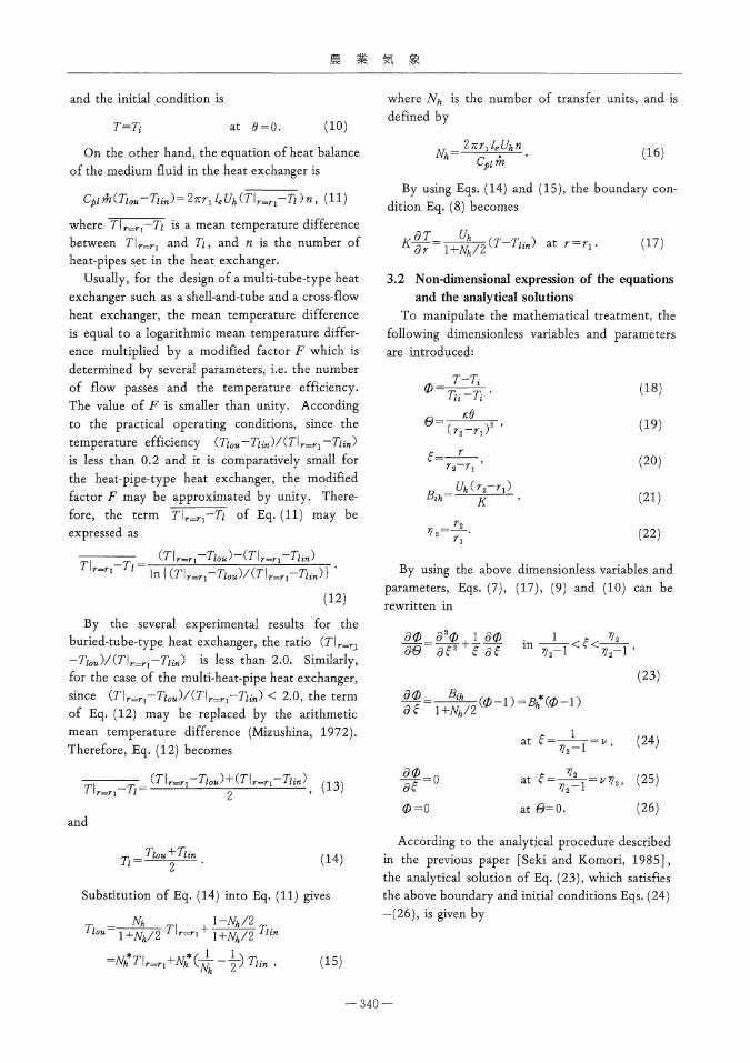
and the initial condition is
T=Ti at Į=0. (10)
On the other hand, the equation of heat balance
of the medium fluid in the heat exchanger is
where T I1-Ti is a mean temperature difference between T|r=r1 and Tl, and n is the number of heat-pipes set in the heat exchanger.
Usually, for the design of a multi-tube-type heat
exchanger such as a shell-and-tube and a cross-flow heat exchanger, the mean temperature differenceis equal to a logarithmic mean temperature differ-
ence multiplied by a modified factor F which isdetermined by several parameters, i.e. the number of flow passes and the temperature efficiency. The value of F is smaller than unity. According
to the practical operating conditions, since the temperature efficiency (Tlou-Tlin)/(T| r=rl-Tlin)
is less than 0.2 and it is comparatively small for the heat-pipe-type heat exchanger, the modifiedfactor F may be approximated by unity. There-fore, the term T|r=r1-Tl of Eq. (11) may be expressed as
(12)
By the several experimental results for the buried-tube-type heat exchanger, the ratio (T r=rl -Tl ou)/(T|r=rl-Tlin) is less than 2.0. Similarly, for the case of the multi-heat-pipe heat exchanger,
since (T|r=r1-Tlou)/(T|r=r1-Tlin) < 2.0, the term of Eq. (12) may be replaced by the arithmetic mean temperature difference (Mizushina, 1972). Therefore, Eq, (12) becomes
(13)
and
(14)
Substitution of Eq. (14) into Eq. (11) gives
(15)
where Nh is the number of transfer units, and is
defined by
(16)
By using Eqs. (14) and (15), the boundary con-
dition Eq. (8) becomes
(17)
3.2 Non-dimensional expression of the equations
and the analytical solutions
To manipulate the mathematical treatment, the
following dimensionless variables and parameters
are introduced:
(18)
(19)
(20)
(21)
(22)
By using the above dimensionless variables and
parameters, Eqs. (7), (17), (9) and (10) can berewritten in
(23)
(24)
(25)
(26)
According to the analytical procedure describedin the previous paper [Seki and Komori, 1985],
the analytical solution of Eq. (23), which satisfies the above boundary and initial conditions Eqs. (24) -(26) , is given by
340
H. Seki and T. Komori: Heat Extraction from a Compost Bed by a Multi-Heat-Pipe Heat Exchanger
(27)
and, Tlou is
(28)
where Zm(x) and Bm(x) are expressed by Eqs. (29) and (30), respectively, and ct iss the n-th positive root of Eq. (31):
(29)
(30)
(31)
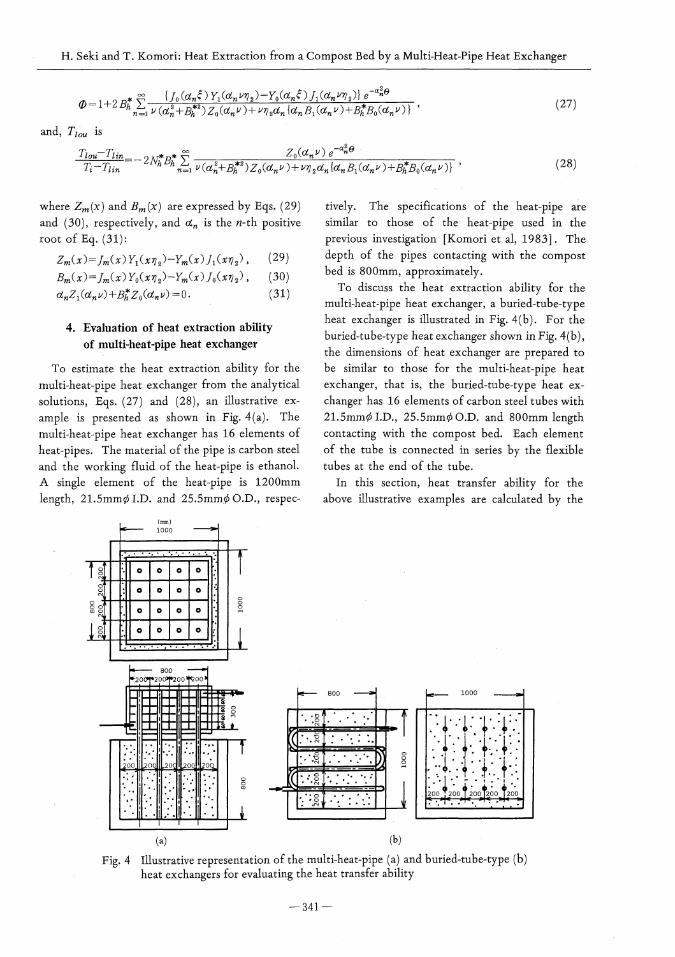
4. Evaluation of heat extraction ability
of multi-heat-pipe heat exchanger
To estimate the heat extraction ability for the
multi-heat-pipe heat exchanger from the analytical
solutions, Eqs. (27) and (28), an illustrative ex-
ample is presented as shown in Fig. 4(a). The
multi-heat-pipe heat exchanger has 16 elements of
heat-pipes. The material of the pipe is carbon steel
and the working fluid of the heat-pipe is ethanol.
A single element of the heat-pipe is 1200mm
length, 21.5mmƒÓI.D. and 25.5mmƒÓ O.D., respec-
tively. The specifications of the heat-pipe are
similar to those of the heat-pipe used in the
previous investigation [Komori et al, 1983]. The
depth of the pipes contacting with the compost
bed is 800mm, approximately.
To discuss the heat extraction ability for the
multi-heat-pipe heat exchanger, a buried-tube-type
heat exchanger is illustrated in Fig. 4(b). For the
buried-tube-type heat exchanger shown in Fig. 4(b),
the dimensions of heat exchanger are prepared to
be similar to those for the multi-heat-pipe heat
exchanger, that is, the buried-tube-type heat ex-
changer has 16 elements of carbon steel tubes with
21.5mmƒÓ I.D., 25.5mmƒÓ O.D. and 800mm length
contacting with the compost bed. Each element
of the tube is connected in series by the flexible
tubes at the end of the tube.
In this section, heat transfer ability for the
above illustrative examples are calculated by the
(a) (b)
Fig. 4 Illustrative representation of the multi-heat-pipe (a) and buried-tube-type (b) heat exchangers for evaluating the heat transfer ability
341

農 業 気 象
analytical solutions under the several operating conditions. 4.1 Overall heat transfer coefficient
As mentioned above, the analytical solutions for the multi-heat-pipe heat exchanger are similar to the approximate analytical solutions for theburied-tube-type heat exchanger. Therefore, theheat extraction ability may be evaluated by com-
paring the values of the overall heat transfer coefficient for the two exchangers.
For the case of the multi-heat-pipe heat ex-changer, the overall heat transfer coefficient Uh is given by Eq, (6). The overall heat transfer coefficient Ub for the buried-tube-type heat
exchanger is [Seki and Komori, 1984]
(32)
Generally, the flow rate and temperature of
medium in the heat exchanger have influence on
the heat transfer coefficients h~ in Eq. (6) and h1 in Eq. (32). In the practical heat extraction
process from the compost bed, since the tempera-ture of the medium rises to the maximum limit within 30°C at the outlet of heat exchanger [Seki
and Komori, 1985b], consequently, h~ and h1 aredependent on the flow rate of medium fluid only. In the illustrative examples, h~ could be estimated by Hilpert's equation for the forced convective
heat transfer at the outer surface of the circular tube [JSME, 1985], and h1 was evaluated from Colburn's equation [Uchida, 1972].
The values of several heat transfer coefficients and thermal conductivity of wall material of the buried tube or heat-pipe are shown in Table 1.
Table 2 summarizes the calculated results of the overall heat transfer coefficients by Eqs. (6) and
(32) with the flow rate of the medium fluid. The overall heat transfer coefficients increases gradually with the flow rate of the medium fluid, and there
Table 1 Values of the several heat transfer coefficients and thermal conductivity of wall material of the buried tube or heat-pipe
Table 2 Calculated results of hi, hc, Ub, Uh and Uh f Ub for some values of the flow rate of medium fluid
342

H. Seki and T. Komori: Heat Extraction from a Compost Bed by a Multi-Heat-Pipe Heat Exchanger
is a small variation of the values of Ub and Uhagainst the flow rate of water. According to the calculated results for the case of the buried-tube-type heat exchanger, the thermal resistance at the
tube-compost interface is dominant, and Ub is equivalent to hs. For the case of the multi-heat-
pipe heat exchanger, the resistance of the heat-pipe (2le/r1)/h is almost equal to the thermal resistance at the heat-pipe-compost interface 1/he, and the overall heat transfer coefficient Uh becomes 1/2 Ub approximately.
4.2 Period for heat extraction, water tempera-ture at the outlet of heat exchanger and
rate of heat extraction The heat extraction ability may be evaluated by
the calculated results of three items, the period available for heat extraction Bext, the average
temperature of water at the outlet of the heat exchanger Tlou , and the average, of the rate of heat extraction from the compost bed per unit volume of compost gext.
As described in Section 3.2, the analytical solu-tions of the temperatures of the compost bed and the medium fluid for the case of the multi-heat-
pipe heat exchanger are similar to the approximate solutions for the buried-tube-type heat exchanger, so that Tlou and gext may be expressed as follows:
(33)
(34)
and Įext is a root of the following equation [Seki and Komori, i985]:
(35)
Fig. 5 Calculated results of Bext, Tiou and gext
plotted against the flow rate of water under
the operating conditions of Ti = 65•Ž and
Tlin =10•Ž, and for the physical properties
of the compost bed K=0.6kcal/mhr•Ž,
Cp = 0.76kcal/kg•Ž and p = 700kg/m3
In Fig. 5, the calculated results of Įext, Tiou
and gext are plotted against the flow rate of
medium fluid at Ti=65•Ž and Tlin=10•Ž. From
Fig. 5, it is clear that gext and Tlou-Tlin for the
multi-heat-pipe heat exchanger are about 30%
smaller than those for the buried-tube-type heat
exchanger. On the other hand, the amount of heat
possible to extract from the compost bed is pro-
portional to Ti-Tavf , and the following relation-
ship between qext and Įext holds in the heat
extraction process:
(36)
In this illustrative example, Įext for the multi-
heat-pipe heat exchanger is about 50% larger than
that for the buried-tube-type heat exchanger.
4.3 A simple calculation method for comparison
of the heat extraction ability of the heat
exchangers
As mentioned above, in Section 4,2, the items
gext , Bext and Tiou , which are index parameters
of the heat extraction ability of the heat exchanger,
can be estimated theoretically by Eqs. (33), (34)
and (35), however, the calculation of these items
by the above equations is very complicated. Only
for estimation of guide on heat extraction per-
343

農 業 気 象
formance of the heat exchangers, it is advisable to
simplify the calculation method for comparison
of the heat extraction ability. Then, simplification
of the calculation method is described here.
Now, by introducing a factor H similar to a
heat conductance, the rate of heat transfer from
the compost bed to the wall o£ the heat-pipe is
expressed as follows:
(37)
By applying the analytical solution Eq, (27) toEq. (37), Hh is obtained by
(38)
Similarly, a factor Hb for the buried-tube-typeheat exchanger is equivalent to Eq. (38) by chang-ing a subscript h into a subscript b. As is obvious
from Eq. (38), Hh depends on time, Fig. 6 showsthe changes of Hh and Hb with the dimensionlesstime. The values of Hh and Hb significantly
change during the period from to, however, these factors become constant for
. From the calculated results, it is suggested that heat penetrates rapidly toward the wall of the heat-pipe or the tube from the compost bed at
the beginning of heat extraction. For >0.25 the change of Q with time gradually becomes small, and the heat transfer in the compost bedreaches the quasi-steady state. Therefore, assuming
that heat conduction in the compost bed may be maintained at the quasi-steady state approximately, a factor Uc corresponding to a heat conductanceof the compost bed may be given by the following equation (Appendix) :
(39)
The value of Uc is 29.5 kcal/m2 hr•Ž in this
illustrative example. According to Fig. 7, the range
of Hh or Hb is from 33.3 to 33.6 kcal/m2 hr•Ž for
> 0.25, and the values of Hh and Hb are almost
equal to the value of Uc . Therefore, Hh and Hb
may be replaced by Uc for >0.25, and the rate
of heat transfer Q for both of the multi-heat-pipe
and buried-tube-type heat exchangers may be
written by the following simple forms, using a
temperature difference Tav-Tl as a total driving
Fig. 6 Changes of factors Hh and Hb with time for the both cases of the multi-heat-pipe and buried-tube-type heat exchangers [(a) at m =150kg/hr, (b) at m=300kg/hr, (c) at m=600kg/hr]
Fig. 7 Comparison of the average value of totaltemperature difference Tav-Tl for the multi-heat-pipe heat exchanger with that for the buried-tube-type heat exchanger
344

H. Seki and T. Komori: Heat Extraction from a Compost Bed by a Multi-Heat-Pipe Heat Exchanger
force of temperature over the heat transfer
processes:
for multi-heat-pipe heat exchanger, (40)
for buried-tube-type heat exchanger, (41)
where UTh and UTb are defined by total heat
conductances over the heat transfer processes, and
are expressed as
(42)
(43)
From the calculated results, since there is a
slight difference in Tav-Tl between the two
exchangers as shown in Fig. 7, the value of qexth /
qextb is almost equal to the ratio of the total heat conductance UTh/UTb . Consequently, UT is a
representative term for estimation of the heat
extraction ability of the heat exchanger. At the
beginning of the heat extraction process, since Hh
or Hb is a function of time and UT is not available
for estimating Tav and Tiou exactly.
5. Conclusions
The problem of heat extraction from the com-
post bed with a multi-heat-pipe heat exchanger was solved analytically. The heat extraction ability
was calculated numerically by the analytical solu-
tions, using the illustrative examples of heat
extraction for the multi-heat-pipe and buried-tube-
type heat exchangers. The following results were
obtained.
1. For the heat extraction from the compost
bed with the multi-heat-pipe heat exchanger, the
solutions of the temperature profile in the compost
bed and the temperature of water at the outlet of
the heat exchanger were obtained, and the solu-
tions were similar to the approximate analytical
solutions for the buried-tube-type heat exchanger.
2. For the several operating conditions, the
overall heat transfer coefficient Uh of the multi-
heat-pipe heat exchanger was about 50% of the
overall heat transfer coefficient Ub for the buried-
tube-type heat exchanger, and the rate of heat
extraction was approximately 30% smaller than
that of the buried-tube-type heat exchanger.
3. The heat extraction ability of the two heat
exchangers can be estimated by a total heat conductance UT for qext. An evaluation of the
heat transfer ability by UT is convenient and simple.
4. For the heat extraction from the compost by the multi-heat-pipe heat exchanger, the timerequired to extract the heat will be larger compared
with that for heat extraction by the buried-tube-type heat exchanger. However, a steady compost-ing reaction or methabolism of thermophilic
aerobic microorganisms will be maintained during the heat extraction process without a rapid change of the temperature in the compost materials around the heat-pipe.
5. The multi-heat-pipe heat exchanger does not require the troublesome works, removing andretubing the tubes for medium fluid in remixing
the compost materials, so that it will be one of the available heat extractors for extraction of heat from the compost bed.
Appendix Derivation of Eq. (39)
For the case of steady state, supposing that
T=T|r=r1 at r=r1, T=T2 at r=r2, the temperature
profile of a hollow cylinder is (Carslaw and Jaeger, 1959)
(A-1)
The average temperature of a hollow cylinder is
(A-2)The heat flux at r=r1 is
(A-3)
Substitution of Eq. (A-2) into Eq. (A-3) gives
(A-4)
From Eq. (A-4), Uc is
(A-5)
345
農 業 気 象
Nomenclature
Bi = Biot number [-]
Cp = heat capacity of compost bed [kcal/kg•Ž]
H = factor corresponding to heat conductance
of compost bed [kcal/m2 hr•Ž]
h = effective heat transfer coefficient of heat-
pipe [kcal/m2 hr•Ž]
hc = liquid film heat transfer coefficient at
water-heat-pipe interface [kcal/m2 hr•Ž]
he = heat transfer coefficient at compost-heat-
pipe interface [kcal/m2 hr•Ž]
hi = liquid film heat transfer coefficient at
water-tube interface [kcal/m2 hr•Ž]
hs = heat transfer coefficient at compost-tube
interface [kcal/m2 hr•Ž]
K = effective thermal conductivity of compost
bed [kcal/mhr•Ž]
Kw = thermal conductivity of material of tube
for medium fluid [kcal/mhr•Ž]
lc = length of heat output region of heat-pipe
[m]
le = length of heat input region of heat-pipe
[m]
m = mass velocity of medium fluid passing
through heat exchanger [kg/hr]
N = number of transfer units [-]
n = number of heat-pipes set in heat
exchanger [-]
Q = rate of heat transfer [kcal/hr]
Q1 = rate of heat transfer from compost bed
to heat-pipe [kcal/hr]
Q2 = rate of heat transfer to axial direction of
heat-pipe [kcal/hr]
Q3 = rate of heat transfer from compost bed
to medium fluid [kcal/hr]
gext = average of rate of heat extraction per unit
volume of compost bed [kcal/m3 hr]
r = distance in radial direction [m]
r1 = outer radius of heat-pipe [m]
r2 = apparent radius o£ compost bed available
for heat extraction [m]
T = temperature in compost bed [•Ž]
Tav = average temperature in compost bed [•Ž]
Tavf = average temperature in compost bed at
the end of water supply [•Ž]
Tc = temperature at the wall of cooler portion
of heat-pipe [•Ž]
Te = temperature at the wall of warmer portion
of heat-pipe [•Ž]
Ti = initial temperature in compost bed [•Ž]
Tl = temperature of water in heat exchanger
[•Ž]
Tlin = temperature of water at the inlet of heat
exchanger [•Ž]
Tiou = temperature of water at the outlet of heat
exchanger [•Ž]
Tiou = average of Tiou over the period of heat
extraction [•Ž]
U = overall heat transfer coefficient
[kcal/m2 hr•Ž]
Uc = heat conductance of compost bed
[kcal/m2 hr•Ž]
UT = total heat conductance for heat extraction
process [kcal/m2 hr•Ž]
V = volume of compost bed [m3]
ƒ³ = dimensionless temperature of compost
bed [-]
= dimensionless time [-]
Į = time [hr]
Įext = period available for heat extraction [hr]
k = effective thermal diffusivity of compost
bed [m2 /hr]
ƒÌ= dimensionless distance in r direction [-]
ā2 = dimensionless parameter defined by
Eq. (22) [-]
ƒÏ = apparent density of compost bed [kg/m3]
subscripts
b = buried-tube-type heat exchanger
h = multi-heat-pipe heat exchanger
References
Carslaw, H. S. and Jaeger, J. C., 1959: Conduction of heat in solids, 2nd ed. Clarendon Press, Oxford, 189.
Chi, S. W., 1976, translated into Japanese by Ohshima, K., Matsushita, T, and Murakami, M., 1978: Heat pipe theory and practice. JATEC Shuppan, Tokyo, 37-167.
JSME, 1976: Data on heat transfer engineering, third ed. JSME, 35 (in Japanese).
Komori, T., Seki, H. and Chikata, Y., 1983: Heat extraction from a compost bed by using a heat-
pipe. Proc. of Hokuriku Chapter of Agr. Met. Soc., 8, 35-42 (in Japanese).
Mizushina, T., 1972: Chapter 3 Heat transfer. In Theory and calculation of chemical engineering (ed. by S. Kamei). Sangyo tosho, Tokyo, 73-116 (in Japanese).
346

H. Seki and T. Komori; Heat Extraction from a Compost Bed by a Multi-Heat-Pipe Heat Exchanger
Seki, H. and Komori, T., 1984: A proposal and trial of heat extraction from a compost bed by water flowing through the pipe buried in the bed. J. Agr. Met., 40(3), 219-228 (in Japanese).
Seki, H. and Komori, T., 1985a: A proposal and trial of heat extraction from a compost bed by water flowing through the pipe buried in the bed (Part 2. An investigation on approximate solutions and operating conditions). J. Agr. Met., 41(1), 57-61 (in Japanese).
Seki, H, and Komori, T., 1985b: A Study of
Extraction and Accumulation of the Heat Generated in Composting Process (Part 1. Ex-
periments for Heat Extraction and Accumulation by Water Circulation). J. Agr. Met., 41(3), 257-264 (in Japanese).
Sun, K. H, and Tien, C. L., 1975: Thermal per-formance characteristics of heat pipes. Int. J Heat Mass Transfer, 18, 363-380.
Uchida, H., 1972: Heat transfer engineering, Shokabo, Tokyo, 129-146 (in Japanese).
マルチ ・ヒー トパイプ熱交換器 による
堆肥発酵熱抽 出に関す る理論的研究
関 平 和 ・小 森 友 明
(金沢大学工学部土木建設工学科)
要 約
埋設管型熱交換 器を用 いる方法は,堆 肥そ うか らの熱
抽 出において典 型的で簡単な方法 であるが,混 合素材の
切返 しを行 う際に埋設 管の取 り外 し,再 配管な どの煩雑
な作業を必要 とする。 このよ うな煩雑な作業を簡単 にす
るため にマルチ ・ヒー トパ イプ熱交換器を用いたユニー
クな熱抽 出方法を提示 し,熱 抽 出過程 におけ る堆肥 そう
内温度及 び熱交換器 出口における熱媒体 の温度 の解析解
を導 いた。 これ らの解 は埋設管型熱交換器 に対す る解 と
数学的 に同一であった。そ して,解 析解 に基 づき,マ ル
チ ・ヒー トパ イプ熱交換器の熱抽出能力 を計算 した。
347