Embed Size (px)
Citation preview
A Tool for Simplified Creation of MPEG4-Based Virtual Talking Heads
F R E D R I K H E D B E R G
Master of Science Thesis Stockholm, Sweden 2006

A Tool for Simplified Creation of MPEG4-Based Virtual Talking Heads
F R E D R I K H E D B E R G
Master’s Thesis in Speech Communication (20 credits) at the School of Media Technology Royal Institute of Technology year 2006 Supervisor at CSC was Jonas Beskow Examiner was Björn Granström TRITA-CSC-E 2006:057 ISRN-KTH/CSC/E--06/057--SE ISSN-1653-5715 Royal Institute of Technology School of Computer Science and Communication KTH CSC SE-100 44 Stockholm, Sweden URL: www.csc.kth.se

Abstract
The aim of this master’s thesis was to develop a tool for easier creation of animated talking heads, using the latest animation platform developed at the department of Speech, Music and Hearing at KTH. This animation platform is based on the new, international MPEG4-standard for face- and body animation and it allows for arbitrary static face models to be animated and used for speech synthesis. To animate a static face model with the platform, some features of the face model have to be defined manually by the user. These features include definition of 38 feature points scattered across the face. The tool created within this thesis improves the system and makes this definition process easier than before. It also closes the gaps between the different parts of the system and achieves a relatively seamless environment for creation of animated talking heads. The tool is implemented as a plug-in for the open-source 3D-modelling software Blender.

Ett verktyg för konstruktion av MPEG4-baserade
talande huvuden Sammanfattning
Syftet med det här examensarbetet var att ta fram ett verktyg som underlättar skapandet av animerade, tredimensionella talande huvuden med det senast framtagna animeringssystemet på institutionen för Tal, Musik och Hörsel på KTH. Det är ett system som är baserat på den nya, internationella MPEG4-standarden för ansikts- och kroppsanimering och det kan ta en godtycklig, tredimensionell ansiktsmodell och animera denna för användning inom talsyntes. För att systemet ska kunna animera en statisk ansiktsmodell så behöver det viss information om ansiktets geometri och form. Den största delen av den här informationen består i 38 s.k. feature punkter, spridda över ansiktet och som användaren måste definiera manuellt. Det framtagna verktyget gör den här definitionen, taggningen, av feature punkterna till en snabbare och enklare process än vad som var fallet från början. Verktyget binder också samman systemets olika delar så att en relativt sömlös utvecklingsmiljö erhålles. Verktyget är implementerat som en plug-in till det fria 3D-modelleringsprogrammet Blender.

Table of Contents Introduction ................................................................................................................................. 1 Background................................................................................................................................... 3
Facial animation ...................................................................................................................... 3 Interpolation........................................................................................................................ 3 Performance-based animation .......................................................................................... 4 Muscle-based animation .................................................................................................... 4 Direct parameterization ..................................................................................................... 5
Parameterization...................................................................................................................... 5 MPEG-4 based facial animation........................................................................................... 6
Face Animation Parameters, FAPs .................................................................................. 6 Facial Definition Parameters, FDPs ................................................................................ 7 Face Animation Parameter Units, FAPUs...................................................................... 8 The ideal parameterization and MPEG-4....................................................................... 9
The MPEG-4 based FA-system at KTH........................................................................... 10 Requirements on a MPEG-4 implementation ............................................................. 10 Structure of the pf-star animation platform ................................................................. 11
Modelcreation............................................................................................................... 12 Engine............................................................................................................................ 16 JFacePlayer.................................................................................................................... 16
Limitations......................................................................................................................... 16 The purpose ...................................................................................................................... 17
Method........................................................................................................................................ 18 Addressing the problem....................................................................................................... 18
Blender ............................................................................................................................... 18 Python ................................................................................................................................ 19 Blender and obj-files ........................................................................................................ 20
Description of the plug-in ................................................................................................... 21 The first plug-in: feature point tagging.......................................................................... 21 The second plug-in: defining hierarchy and creating the scene................................. 24
XML-RPC..................................................................................................................... 25 Summary ............................................................................................................................ 26
Results ......................................................................................................................................... 27 The overall result................................................................................................................... 27 Tested models........................................................................................................................ 27
Don..................................................................................................................................... 27 James .................................................................................................................................. 28 Kattis .................................................................................................................................. 28
Analysis ....................................................................................................................................... 31 Limitations of Blender.......................................................................................................... 31
Correct .OBJ-files ............................................................................................................. 31 Limitations of the tool.......................................................................................................... 31
The server .......................................................................................................................... 31 Multiple files...................................................................................................................... 31
Limitations of the animation system.................................................................................. 32 Correct .OBJ-files ............................................................................................................. 32
Further development ............................................................................................................ 32 Conclusion.................................................................................................................................. 33 References................................................................................................................................... 34 A. Glossary.......................................................................................................................... 35

Introduction
1
Introduction
Multimodal speech synthesis and computer-based facial animation are not at all new endeavors. Research on how to represent human faces by using computers has been going on for well over 30 years, but in the recent years the interest in facial animation has increased, an interest awakened predominantly by the entertainment industry with an explosion of computer animated movies, but also computer games with higher and higher demands on visually realistic characters (Parke et al., 1996).
The face is one of the most important elements in human communication. When speaking face to face with other humans, a significant part of the conversational information is obtained through interpreting the flood of subtle facial cues and signs produced by the other participants. These cues tell us a great deal: they tell us what mood a person is in; they give expressional information and they show how the other participants are reacting to the conversation; they can emphasize statements; they can give information that keep the conversation smooth, such as turn-taking cues. Most important for this thesis though, are the cues that carry information about the speech production. By watching the teeth, lips and tongue of a speaking person, we obtain information that we can add to the perceived audio signal and hereby increase the chance of interpreting the information correctly. This makes it possible to keep conversation in noisy environments and it makes it possible for hearing impaired to participate in conversations (Beskow 2003).
The research on how to produce realistic speech using computers has been going on for over 40 years and this research has now lead to dialogue systems and other applications that are used by people on a daily basis.
Combining these two fields of science gives us multimodal speech synthesis; a research branch that is now attracting an increased interest from outside the scientific community. The emergence of interactive agents on the internet, the growing popularity of dynamically animated characters in computer games and the desire to develop improved helping aids for hearing disabled have helped to fuel this interest.
To this date, the main focus of the research has been on developing interactive avatars, or talking heads, for spoken dialogue systems. An avatar is used in a dialogue system to emphasize the audio information given by the system. The tasks of the animated avatar are to support the conversation by producing recognizable facial cues to the human user. At the department of Speech, Music and Hearing on KTH several dialogue systems have been developed through out the years, with ever increased quality, both of the speech synthesis and of the facial animation. The increased quality of the facial animation depends to a large extent on better use and understanding of the facial cues used in conversation mentioned above. Of course, new technology with improved hardware, animation algorithms and new renderers also adds to that increased quality.
The latest addition to this line of systems is an animation platform born under the EU-project pf-star. This new animation platform, developed at KTH is based on Java, OpenGL, XML and the MPEG-4 facial animation standard, launched by the MPEG-group (2002a). It makes use of sophisticated animation- and rendering techniques and can produce high-quality facial animations (Granström, 2005). The real breakthrough with this platform though, is the possibility to create a facial animation from any arbitrary, static, three-dimensional face model. This means that, provided the animation platform gets the

Introduction
2
information necessary, anyone of the existing, three-dimensional face models can be used for facial animation and speech synthesis with this platform. What that necessary information consists of is, to a large extent, reference points of different features in the face. The animation platform needs to know certain feature points of the face, so that the face’s proportions and key features become known. This definition of the reference points have to be done manually by the user. Unfortunately though, this has been a quite tedious and time-demanding work the way the system was originally built. Certain limitations in the system have had the effect that the system has not made use of its full potential.
The aim of this master’s thesis was to modify the system and overcome these limitations. I was asked to develop a tool, to make the creation of MPEG-4 based virtual talking heads with the system, easier.
The demands were to develop a tool to make the definition of the reference points easier and faster; preferably an easy-to-use, intuitive, graphical tool.
Another demand was to integrate the different parts of the system into a seemingly seamless unity to make the animation process as swift and smooth as possible.
Background
3
Background
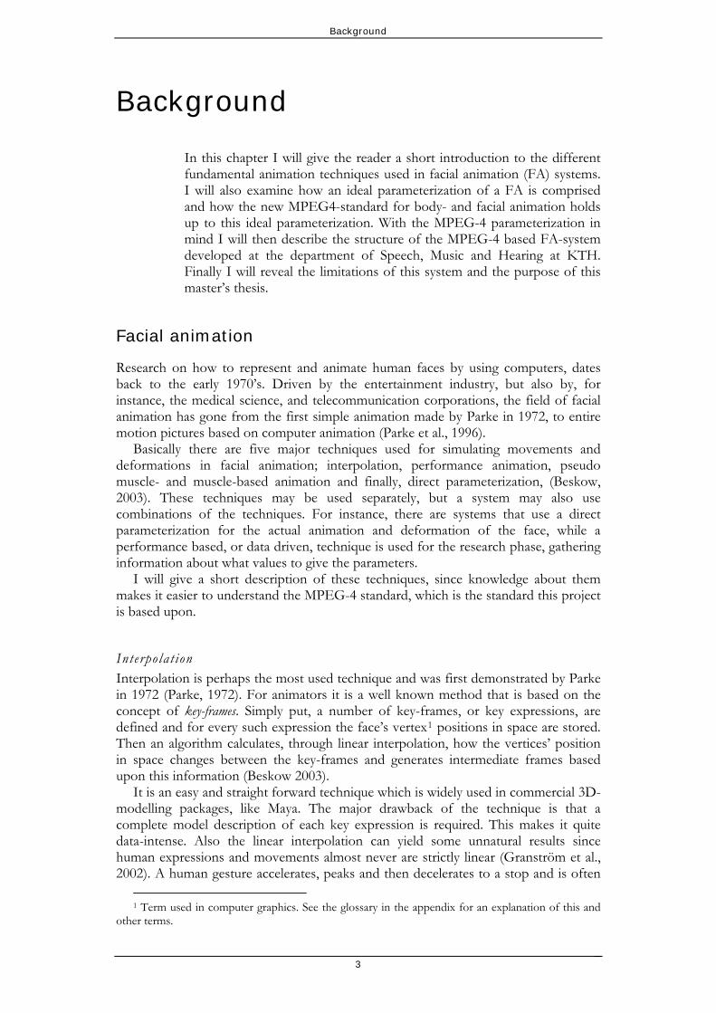
In this chapter I will give the reader a short introduction to the different fundamental animation techniques used in facial animation (FA) systems. I will also examine how an ideal parameterization of a FA is comprised and how the new MPEG4-standard for body- and facial animation holds up to this ideal parameterization. With the MPEG-4 parameterization in mind I will then describe the structure of the MPEG-4 based FA-system developed at the department of Speech, Music and Hearing at KTH. Finally I will reveal the limitations of this system and the purpose of this master’s thesis.
Facial animation
Research on how to represent and animate human faces by using computers, dates back to the early 1970’s. Driven by the entertainment industry, but also by, for instance, the medical science, and telecommunication corporations, the field of facial animation has gone from the first simple animation made by Parke in 1972, to entire motion pictures based on computer animation (Parke et al., 1996).
Basically there are five major techniques used for simulating movements and deformations in facial animation; interpolation, performance animation, pseudo muscle- and muscle-based animation and finally, direct parameterization, (Beskow, 2003). These techniques may be used separately, but a system may also use combinations of the techniques. For instance, there are systems that use a direct parameterization for the actual animation and deformation of the face, while a performance based, or data driven, technique is used for the research phase, gathering information about what values to give the parameters.
I will give a short description of these techniques, since knowledge about them makes it easier to understand the MPEG-4 standard, which is the standard this project is based upon.
Interpolat ion Interpolation is perhaps the most used technique and was first demonstrated by Parke in 1972 (Parke, 1972). For animators it is a well known method that is based on the concept of key-frames. Simply put, a number of key-frames, or key expressions, are defined and for every such expression the face’s vertex1 positions in space are stored. Then an algorithm calculates, through linear interpolation, how the vertices’ position in space changes between the key-frames and generates intermediate frames based upon this information (Beskow 2003).
It is an easy and straight forward technique which is widely used in commercial 3D-modelling packages, like Maya. The major drawback of the technique is that a complete model description of each key expression is required. This makes it quite data-intense. Also the linear interpolation can yield some unnatural results since human expressions and movements almost never are strictly linear (Granström et al., 2002). A human gesture accelerates, peaks and then decelerates to a stop and is often
1 Term used in computer graphics. See the glossary in the appendix for an explanation of this and
other terms.
Background
4
better described with a nonlinear function. To overcome this, a nonlinear interpolation is required.
Performance-based animation Performance-based (or data-driven) techniques use information obtained from measuring real human facial movements and actions to drive animated, synthetic faces. This information may be obtained in a number of different ways, of which motion tracking of reference points attached to the object, with video or laser-systems, is the most common. For some animation purposes, information about how the articulatory organs move inside the body during speech is required. For this, electromyography (EMG), electropalatography (EPG) or electromagnetic articulography (EMA) can be used (Beskow 2003).
The information used in data-driven animation needs to have a high spatial resolution in order to generate a natural looking animation (Beskow 2003).
Muscle -based animation Perhaps the most natural and accurate way to animate a synthetic face would be to mimic the human anatomy of the face. With simulated muscles a control scheme, or a set of rules, which follows the anatomical limitations of the human face can be obtained. This control scheme can be used to achieve an anatomical correct deformation and translation of the face’s vertices. The biggest advantage of this technique is that no unnatural or physiologically impossible deformations of the face can be created.
The simplest case of muscle-based animation, pseudo-muscle based animation, is a direct parameterized method that simply uses the muscle structure of the face to limit the values of the parameters and hence limit the possible translations and deformations of the face vertices. The soft tissues of the face, such as the skin, fat and cartilage are not taken into consideration with this method (Parke et al, 1996).
An enhanced technique that includes simulation of the skin and the other soft tissues of the face was introduced by Platt and Badler (Platt et al., 1981). To simulate the skin’s elasticity they inter-connected the vertices of the face with virtual springs; the skin was thought of as a mesh of springs. In addition, this mesh of springs was attached to the underlying bone structure of the face by modeled pseudo-muscles. When the forces from these muscles were applied to a vertex in the mesh, the movement of that vertex propagated through the mesh to nearby vertices; the virtual skin of the face was deformed and this way, different facial expressions could be obtained.
An even more detailed simulation of the anatomical structure of the face was presented by Waters (1987). He also tried to model the effects of muscle action upon skin, but with a different approach than Platt and Badler. Waters introduced a model where two different muscle types were simulated; linear muscles that contracts and elliptic sphincter muscles that squeeze around certain facial features; the eye or the mouth for instance. The linear muscles are attached on one end to the bony structure of the face and on the other end to the simulated skin. The amount and direction of the translation of a vertex on the skin is determined as a function of the position of the vertex relative to the muscle’s attachment area. The further from the attachment area the vertex is, the lesser the muscle’s influence over the vertex (Parke et al., 1996).
Since it is difficult to measure the actions of real muscles, setting the parameters for the simulated muscles can be very difficult (Noh et al., 1998). It is also a quite data-intense method and for real-time applications, such as interface agents or avatars, this is a major drawback (Granström et al., 2002).

Background
Direc t parameter izat ion The direct parameterization method was introduced as an attempt to overcome the problems associated with the interpolation-based method; i.e. the need to store a large number of key expressions. The desire was instead to be able to control facial expressions with a relatively small, data efficient, set of control parameters (Parke et al., 1996). These parameters simply describe translations and displacements of the face’s surface and do not model any underlying structures or anatomy, such as muscles, tissues or bones. This makes the method data-efficient. The parameters are obtained through observation of real human faces (Beskow, 2003).
The first parameterization models were presented by Parke and he described a set of parameters divided into two parts, expression and conformation. The expression set includes parameters such as mouth width, upper-lip position, jaw rotation and eyelid opening and with these the animator can control the facial expressions of the face. To describe the anatomy and shape of the actual face the conformation set is used and it includes parameters such as jaw width, nose length, eye size and face proportions (Parke et al., 1996).
A drawback with direct parameterization is that unpredictable results may occur when manipulating multiple parameters at the same time (Granström, et al. 2002).
Parameterization
Whatever technique is used for the low-level face animation described above, a suitable set of control parameters for the high-level animation is required. These control parameters should be defined in such ways that the animation process can be kept at a high-level; the animator should only have to worry about modeling facial expressions, not about how to translate and deform single vertices. A somewhat edited taxonomy of a FA-system is shown in Figure 1 (Pandzic et al., 2002b).
Low-level FA High-level FA
Face animation (FA)
Interpolation of vertex motion
Direct parameterization
Pseudo-muscle models Simulate visual effects of muscles
Muscle models Physical simulation of bone, tissue, muscle and skin
Data-driven animation Capture performance of real actor
Control parameterization
Figure 1: An edited taxonomy of Facial Animation. The control parameters should be defined in such ways that the animator only has to deal with the high-level animation.
Parke described the features of an ideal control parameterization and made a list of the requirements on the parameters in such a parameterization. Pandzic and Forchhemier then extended that list to include the following requirements (Pandzic et al., 2002b):
5

Background
6
Any face with any expression should be possible to express. The parameterization has to be easy to use. This demand conflicts with the
first demand since a wide range of possible expressions requires a more complex parameterization. Keeping the number of parameters down and making them intuitive is the best way of making the parameterization easy to use.
Subtle expressions have to be expressible. When looking at a face we perceive very small movements, a slightly raised brow, a twitch of the corner of the mouth, and interpret them as signs of different emotions. These are a vital part of the communication process.
One parameter should not affect another parameter. The parameters need to be orthogonal.
The result of a parameter change, or a combination of parameters, has to be predictable.
Portability. When applying the same parameters to different face models, the visual result should be the same.
To allow for data-driven animation, the parameters need to be defined in such ways that they are measurable with a high degree of accuracy. They also have to be able to be derived from a natural face.
For streaming and real-time applications, a bandwidth-efficient stream of parameters is desirable.
Depending on the nature of the application though, the demands on the parameterization can be quite different and all of these demands may not have to be met (Beskow, 2003).
MPEG-4 based facial animation
For a very long time, there existed no standard control parameterization. The different FA-systems developed used their own parameterizations and without a standard it was difficult to exchange data and results between the various systems.
The first actual facial control parameterization standard was developed by the Moving Picture Expert Group (MPEG); the MPEG-4 Face and Body Animation standard; a standard which contains specifications on how to animate human bodies and faces. The most important part is the standard set of animation parameters (AP), both low-level and high-level, that are defined. These APs are scalable and can be normalized to an arbitrary face, a property which makes the standard highly portable over different faces and platforms. This has now made it easy for the scientific community to exchange and compare data with each other (Nordenberg, 2005).
In addition, as long as the set of standardized set of parameters are defined for the model, any underlying technique may be used for the actual deformation of the model, for example interpolation, direct parameterization or muscle-models, (Preda et al., 2002).
Face Animation Parameters , FAPs As mentioned above, the most important part of the standard is the set of animation parameters. The MPEG-4 standard for face animation (the part of the standard concerning body animation will not be dealt with in this text) specifies a number of
Background
7
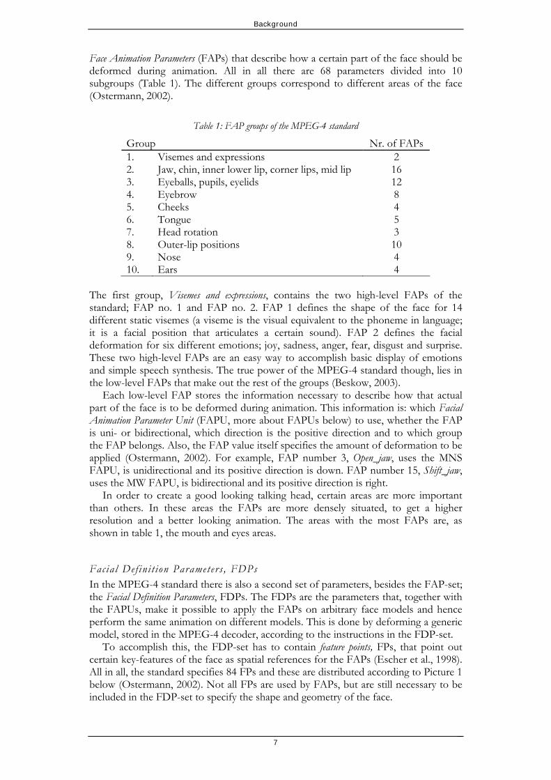
Face Animation Parameters (FAPs) that describe how a certain part of the face should be deformed during animation. All in all there are 68 parameters divided into 10 subgroups (Table 1). The different groups correspond to different areas of the face (Ostermann, 2002).
Table 1: FAP groups of the MPEG-4 standard
Group Nr. of FAPs 1. Visemes and expressions 2 2. Jaw, chin, inner lower lip, corner lips, mid lip 16 3. Eyeballs, pupils, eyelids 12 4. Eyebrow 8 5. Cheeks 4 6. Tongue 5 7. Head rotation 3 8. Outer-lip positions 10 9. Nose 4 10. Ears 4
The first group, Visemes and expressions, contains the two high-level FAPs of the standard; FAP no. 1 and FAP no. 2. FAP 1 defines the shape of the face for 14 different static visemes (a viseme is the visual equivalent to the phoneme in language; it is a facial position that articulates a certain sound). FAP 2 defines the facial deformation for six different emotions; joy, sadness, anger, fear, disgust and surprise. These two high-level FAPs are an easy way to accomplish basic display of emotions and simple speech synthesis. The true power of the MPEG-4 standard though, lies in the low-level FAPs that make out the rest of the groups (Beskow, 2003).
Each low-level FAP stores the information necessary to describe how that actual part of the face is to be deformed during animation. This information is: which Facial Animation Parameter Unit (FAPU, more about FAPUs below) to use, whether the FAP is uni- or bidirectional, which direction is the positive direction and to which group the FAP belongs. Also, the FAP value itself specifies the amount of deformation to be applied (Ostermann, 2002). For example, FAP number 3, Open_jaw, uses the MNS FAPU, is unidirectional and its positive direction is down. FAP number 15, Shift_jaw, uses the MW FAPU, is bidirectional and its positive direction is right.
In order to create a good looking talking head, certain areas are more important than others. In these areas the FAPs are more densely situated, to get a higher resolution and a better looking animation. The areas with the most FAPs are, as shown in table 1, the mouth and eyes areas.
Facial Def ini t ion Parameters , FDPs In the MPEG-4 standard there is also a second set of parameters, besides the FAP-set; the Facial Definition Parameters, FDPs. The FDPs are the parameters that, together with the FAPUs, make it possible to apply the FAPs on arbitrary face models and hence perform the same animation on different models. This is done by deforming a generic model, stored in the MPEG-4 decoder, according to the instructions in the FDP-set.
To accomplish this, the FDP-set has to contain feature points, FPs, that point out certain key-features of the face as spatial references for the FAPs (Escher et al., 1998). All in all, the standard specifies 84 FPs and these are distributed according to Picture 1 below (Ostermann, 2002). Not all FPs are used by FAPs, but are still necessary to be included in the FDP-set to specify the shape and geometry of the face.

Background
Picture 1: The distribution of feature points across the face.
.
The FDP-set can also, but it is not necessary, contain texture coordinates, a Face Scene Graph and Face Animation Tables (FATs, will not be described in this text).
The Face Scene Graph includes a 3D-polygonal mesh of the face, the texture (if any) and the material properties of the face. The 3D-mesh is not the actual model though, but a definition of the shape of the face, used as a calibration model. When adapting the generic model to the input face, the vertices of the generic model are aligned, stretched out, to fit the surface of the calibration model. If no Face Scene Graph is included in the FDP, the FP’s are used to animate the generic model directly instead (Escher et al., 1998).
Face Animation Parameter Units , FAPUs As mentioned above, the MPEG-4 standard allows for arbitrary face models to be animated, regardless of their size or shape. I have described how the FDPs are made to achieve this, but they actually need the help of another small set of parameters; the Face Animation Parameter Units, FAPUs. The FAPUs makes the FAPs scalable between arbitrary face models by defining five different distances between certain points of the face, when the face is in its neutral state2. Their definitions are the following (Ostermann, 2002):
2 A face’s neutral state is when all face muscles are relaxed, the eyes look straight forward, the
eyelids are tangent to the iris, the diameter of the pupil is one third of the diameter of the iris, the mouth is closed and the lips and the upper- and lower teeth are in contact.
8

Background
9
Table 2: The different Face Animation Parameter Units of the MPEG-4 standard.
FAPU Definition 1. IRISD0 Iris diameter, distance between upper and lower eyelid. 2. ES0 Eye separation, distance between the pupils. 3. ENS0 Eye-nose separation, length of the nose. 4. MNS0 Mouth-nose separation, distance between upper lip and
lower end of the nose. 5. MW0 Mouth width.
The ideal parameter izat ion and MPEG-4 I have now described the most essential parts of the MPEG-4 standard and it is now possible to examine how the MPEG-4 parameterization holds up compared to the ideal parameterization mentioned earlier. Pandzic and Forchheimer conclude that (Pandzic et al., 2002b):
Since the FDPs allows for a face to be reshaped in any manner, almost any
face can be represented. The FAPs can be used for expressing a wide range of emotions and gestures.
The FAPs of the MPEG-4 standard are intuitive and, despite that most of them are very low-level, easy to use. There are also the two high-level parameters that allow basic speech animation in a very simple way.
Subtlety can be obtained. The FAPs are not completely independent, or orthogonal. When moving the
chin point FAP for example, other FAPs on and around the jaw are bound to move too.
You can only predict the movements of the FPs, the result of the entire parameter set is more difficult to predict. With the FATs though, you can achieve full predictability.
Since the FAPs are scalable they can be applied to any new face. They are indeed portable.
Almost all parameters of the standard can be measured very exactly. When sending only the high-level FAPs the bit rate of the data stream is
merely 0.3 kbit/s. Sending all FAPs generates a bit stream of 3-6 kbit/s. These low bit rates are achieved by only transmitting the parameters that actually are in use.
In many aspects the MPEG-4 standard holds up to the demands of an ideal parameterization, but not to all. Still it is closer than any other parameterization yet presented and the most important fact is that there actually exists a standard now (Pandzic et al., 2002b).
Background
10
The MPEG-4 based FA-system at KTH
Since the launch of the MPEG-4 standard a number of implementations of it have been made and they all have their own advantages and drawbacks. One of these implementations has been developed at the department of Speech, Music and Hearing at KTH and I made a brief presentation of this in the introduction. This is the animation platform developed under the pf-star project and it is the implementation I have been developing my tool for during the work on this thesis.
Requirements on a MPEG-4 implementat ion Mikael Nordenberg (2005) describes what the main concerns were when this system was developed. He identifies the disadvantages of a number of other implementations and the requirements necessary to overcome these. The five requirements on a MPEG-4 compatible model/animation algorithm that Nordenberg describes are:
1. The algorithm must, based on the FAPs, be able to reproduce the feature
points positions, obtained from a data-driven recording, in an exact manner.
2. In the MPEG-4 standard, FAP values must be kept model independent and the algorithm must strive to obtain this independency.
3. No discontinuities or edge artifacts must be caused by the deformation method. The FAPs must deform the model in a smooth way.
4. Adjacent FAPs must be made to work together. 5. The model should be able to animate in real time, preferably through the
hardware acceleration of a graphic card.
The implementation developed at the department of Speech, Music and Hearing addressed and solved these five issues and I will give a brief review of Nordenberg’s paper on how it was achieved.
The first requirement was solved simply by ensuring that all FAPs were mutually independent (how that was done is explained below). Having established this independency, all that needs do be done to extract a FAP-value from the motion tracking recording, is to measure the offset of the marker in the current position in relation to the marker’s neutral position. With this FAP-value the animation algorithm can then reproduce the FP’s position in an exact manner. If requirement two is to be fulfilled, the applied set of FAPs must keep the relative positions of the FPs the same, regardless of the model; the positions of the FPs have to be deterministic and predictable.
In regions were the feature points are densely situated, such as the mouth region, a feature point may be affected by multiple FAPs at the same time. This is not a problem as long as the FAPs do not affect the feature point in the same direction. If a FP is affected in the same direction by multiple FAPs, the FP’s position ceases to be deterministic; it becomes impossible to predict the position and the FAPs are not mutually independent.
To overcome this problem and make the FAPs mutually independent, the movements in unwanted directions by the FAPs were cancelled by applying the same amount of movement in the negative direction.
Background
To achieve a smooth deformation of the model, to partly fulfill requirement three, each FAP has to be allowed to affect not only the targeted FP, but also the surrounding vertices. To accomplish this, a weight map is defined for each FAP in which the amount of influence of the FAP on each vertex in the model is specified. By choosing a function, that decreases the influence of the FAP with an increased distance to the targeted FP exponentially, a smooth deformation of the model can be achieved.
The standard way of determining the distance between the FP and a surrounding vertex is by calculating the Euclidian distance, the “straight” distance, between the points. In facial areas with cavities though, such as the eyes or the mouth, the Euclidian distance is not very well suited because even though the distance between a feature point on the lower eye-lid and a vertex on the upper eye-lid is very small, the feature point should not affect the other vertex. A weight map based on the Euclidian distance would cause artifacts. The approach used by the team at KTH was to calculate the weight map using the edge distance instead. The edge distance is the minimum distance between two vertices following the polygon edges that connect the vertices. This approach makes the distance between a vertex on the lower eye-lid and a vertex on the upper eye-lid much greater than the Euclidian distance and a more appropriate weight map, that does not cause artifacts and thereby fulfill requirement three, can be obtained.
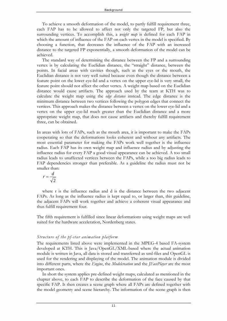
In areas with lots of FAPs, such as the mouth area, it is important to make the FAPs cooperating so that the deformations looks coherent and without any artifacts. The most essential parameter for making the FAPs work well together is the influence radius. Each FAP has its own weight map and influence radius and by adjusting the influence radius for every FAP a good visual appearance can be achieved. A too small radius leads to unaffected vertices between the FAPs, while a too big radius leads to FAP dependencies stronger than preferable. As a guideline the radius must not be smaller than:
2dr =
where r is the influence radius and d is the distance between the two adjacent
FAPs. As long as the influence radius is kept equal to, or larger than, this guideline, the adjacent FAPs will work together and achieve a coherent visual appearance and thus fulfill requirement four.
The fifth requirement is fulfilled since linear deformations using weight maps are well suited for the hardware acceleration, Nordenberg states.
Structure o f the pf -s tar animation plat form The requirements listed above were implemented in the MPEG-4 based FA-system developed at KTH. This is Java/OpenGL/XML-based where the actual animation module is written in Java, all data is stored and transferred as xml-files and OpenGL is used for the rendering and displaying of the model. The animation module is divided into different parts, where the Engine, the Modelcreation and the JFacePlayer are the most important ones.
In short the system applies pre-defined weight maps, calculated as mentioned in the chapter above, to each FAP to describe the deformation of the face caused by that specific FAP. It then creates a scene graph where all FAPs are defined together with the model geometry and scene hierarchy. The information of the scene graph is then
11

Background
outputted as an xml-file which in turn can be played back by the JFacePlayer, with assistance of the Engine. I will describe the parts more thoroughly below.
Modelcreation The Modelcreation-part is responsible for creating the output scene, from the information provided by the input files. It applies the pre-defined weight maps to the FAPs, defines other FAP-data and defines the hierarchy and structure of the scene, as described below.
The modelcreation-module needs three different files as input, shown in Figure 2. From these three files the scene is created.
Model description file
Geometry file - obj
Scene specification - xml
Model-creation Scene - xml
Figure 2: The input files required by the modelcreation-module.
Model description file The model description file contains information about:
Feature points. All FPs required by the system, 38 in the current implementation, need to be defined. Each vertex in the face model has got a unique index number and these index numbers are used to define the FPs.
FAPUs. All five FAPUs need to be defined. Rotation centers (markers). The rotation centers of the eyes and the jaw are
needed. These are given as positions in space. Geometry description. The geometry of the model is described in a separate
geometry file, but due to some imperfections in the export function of the XSI-software, an additional description of the model’s vertices and faces is required in the model description file. The problem with XSI is that the indexation used by XSI to identify the vertices does not correspond to the indexation used by the animation system. So the additional model description is used to map the XSI-indices to the system-indices.
In the original implementation of this FA-system, a 3D-software called XSI was used to do the feature point definitions of the face. The information of the model description file was exported from XSI by a JavaScript.
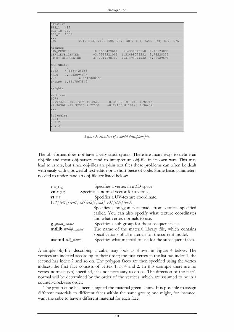
To be compatible with the modelcreation-module, the model description file must have the structure described in Figure 3 below (where Clusters are the feature points).
Geometry file The geometry file contains a complete geometrical description of the face model. The format used is OBJ, a text-based standard used for describing 3D-models. Obj-files can be imported and exported by many different 3D-applications. Since understanding the obj-format is important in order to use the animation platform, I will give a more in depth explanation of it.
12
Background
Clusters FP2_1 487 FP2_10 330 FP2_2 1053 ... JAW 211, 213, 219, 220, 267, 487, 488, 525, 670, 672, 676 Markers JAW_CENTER -0.0665429681 -6.4386072158 1.16673898 LEFT_EYE_CENTER -3.7229321003 1.31498074532 5.76228332 RIGHT_EYE_CENTER 3.72214198112 1.31498074532 5.66029596 FAP_units ES0 7.5 ENS0 7.4892160629 MNS0 2.2082094806 MW0 6.9642000198 IRISD0 1.6517567549 Weights Vertices 1078 -0.97323 -10.17294 10.2627 -0.35929 -0.1018 0.92764 -2.34966 -11.37310 9.22130 -0.24100 0.10928 0.96432 ... Triangles 2024 0 1 2 0 1 3
...Figure 3: Structure of a model description file.
The obj-format does not have a very strict syntax. There are many ways to define an obj-file and most obj-parsers tend to interpret an obj-file in its own way. This may lead to errors, but since obj-files are plain text files these problems can often be dealt with easily with a powerful text editor or a short piece of code. Some basic parameters needed to understand an obj-file are listed below:
v x y z Specifies a vertex in a 3D-space. vn x y z Specifies a normal vector for a vertex. vt u v Specifies a UV-texture coordinate. f v1/[vt1]/[vn1] v2/[vt2]/[vn2] v3/[vt3]/[vn3] Specifies a polygon face made from vertices specified
earlier. You can also specify what texture coordinates and what vertex normals to use.
g group_name Specifies a sub-group for the subsequent faces. mtllib mtllib_name The name of the material library file, which contains
specifications of all materials for the current model. usemtl mtl_name Specifies what material to use for the subsequent faces.
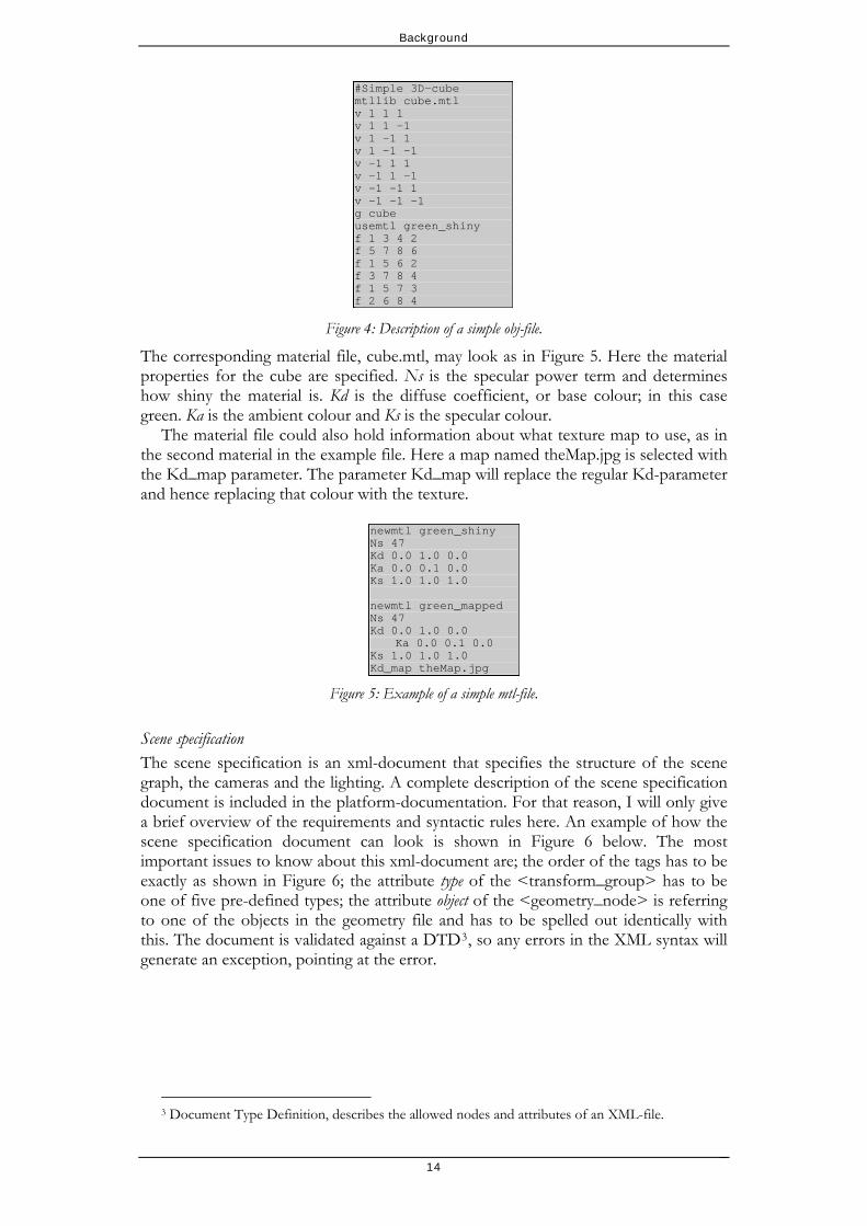
A simple obj-file, describing a cube, may look as shown in Figure 4 below. The vertices are indexed according to their order; the first vertex in the list has index 1, the second has index 2 and so on. The polygon faces are then specified using the vertex indices; the first face consists of vertex 1, 3, 4 and 2. In this example there are no vertex normals (vn) specified, it is not necessary to do so. The direction of the face’s normal will be determined by the order of the vertices, which are assumed to be in a counter-clockwise order.
The group cube has been assigned the material green_shiny. It is possible to assign different materials to different faces within the same group; one might, for instance, want the cube to have a different material for each face.
13
Background
#Simple 3D-cube mtllib cube.mtl v 1 1 1 v 1 1 -1 v 1 -1 1 v 1 -1 -1 v -1 1 1 v -1 1 -1 v -1 -1 1 v -1 -1 -1 g cube usemtl green_shiny f 1 3 4 2 f 5 7 8 6 f 1 5 6 2 f 3 7 8 4 f 1 5 7 3 f 2 6 8 4
Figure 4: Description of a simple obj-file.
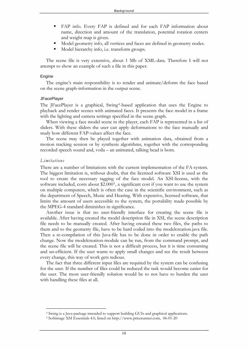
The corresponding material file, cube.mtl, may look as in Figure 5. Here the material properties for the cube are specified. Ns is the specular power term and determines how shiny the material is. Kd is the diffuse coefficient, or base colour; in this case green. Ka is the ambient colour and Ks is the specular colour.
The material file could also hold information about what texture map to use, as in the second material in the example file. Here a map named theMap.jpg is selected with the Kd_map parameter. The parameter Kd_map will replace the regular Kd-parameter and hence replacing that colour with the texture.
newmtl green_shiny Ns 47 Kd 0.0 1.0 0.0 Ka 0.0 0.1 0.0 Ks 1.0 1.0 1.0 newmtl green_mapped Ns 47 Kd 0.0 1.0 0.0
Ka 0.0 0.1 0.0 Ks 1.0 1.0 1.0 Kd_map theMap.jpg
Figure 5: Example of a simple mtl-file.
Scene specification The scene specification is an xml-document that specifies the structure of the scene graph, the cameras and the lighting. A complete description of the scene specification document is included in the platform-documentation. For that reason, I will only give a brief overview of the requirements and syntactic rules here. An example of how the scene specification document can look is shown in Figure 6 below. The most important issues to know about this xml-document are; the order of the tags has to be exactly as shown in Figure 6; the attribute type of the <transform_group> has to be one of five pre-defined types; the attribute object of the <geometry_node> is referring to one of the objects in the geometry file and has to be spelled out identically with this. The document is validated against a DTD3, so any errors in the XML syntax will generate an exception, pointing at the error.
3 Document Type Definition, describes the allowed nodes and attributes of an XML-file.
14

Background
<!DOCTYPE scene_desc SYSTEM "scene_description.dtd"> <scene_desc> <geometry_file location="g:/projects/don.obj"/> <model_desc location="g:/projects/don_export.txt"/> <scene_graph> <transform_group name="head" type="head"> <geometry_node name="skin" object="Skin"/> <geometry_nodename="upper_inner_mouth" object="Upper_inner_mouth"/> <geometry_node name="upper_teeth" object="Upper_teeth"/> <transform_group name="left_eye_group" type="left_eye"> <geometry_node name="left_eye" object="Left_eye"/> </transform_group> <transform_group name="right_eye_group" type="right_eye"> <geometry_node name="right_eye" object="Right_eye"/> </transform_group> <transform_group name="jaw" type="jaw"> <geometry_node name="lower_teeth" object="Lower_teeth"/> <geometry_nodename="lower_inner_mouth" object="Lower_inner_mouth"/> </transform_group> <transform_group name="tongue_group" type="tongue"> <geometry_node name="tongue" object="Tongue"/> </transform_group> </transform_group> </scene_graph> <cameras> <camera> <name>Main camera</name> <position> <vec3 x="0" y="0" z="125"/> </position> <direction> <vec3 x="0" y="0" z="-1"/> </direction> <up> <vec3 x="0" y="1" z="0"/> </up> <vertical_fov>30</vertical_fov> <aspect_ratio>1.33</aspect_ratio> <depth_range> <near>50</near> <far>300</far> </depth_range> </camera> </cameras> <lights> <directional> <direction> <vec3 x="1" y="0" z="1"/> </direction> <color> <rgb r="1" g="1" b="1"/> </color> <intensity>0.8</intensity> </directional> <ambient> <color> <rgb r="1" g="1" b="1"/> </color> <intensity>0.3</intensity> </ambient> </lights> </scene_desc>
Figure 6: A scene specification document, describing a scene with model hierarchy, cameras and lighting.
The output scene When the modelcreation-module has processed the input files, the final output scene file is created. This is another xml-file that contains all information needed to animate the scene in the Engine and the JFacePlayer:
Camera and lighting info. Texture info.
15
Background
16
FAP info. Every FAP is defined and for each FAP information about name, direction and amount of the translation, potential rotation centers and weight map is given.
Model geometry info, all vertices and faces are defined in geometry nodes. Model hierarchy info, i.e. transform groups.
The scene file is very extensive, about 1 Mb of XML-data. Therefore I will not
attempt to show an example of such a file in this paper.
Engine The engine’s main responsibility is to render and animate/deform the face based
on the scene graph-information in the output scene.
JFacePlayer The JFacePlayer is a graphical, Swing4-based application that uses the Engine to playback and render scenes with animated faces. It presents the face model in a frame with the lighting and camera settings specified in the scene graph.
When viewing a face model scene in the player, each FAP is represented in a list of sliders. With these sliders the user can apply deformations to the face manually and study how different FAP-values affect the face.
The scene may then be played together with animation data, obtained from a motion tracking session or by synthesis algorithms, together with the corresponding recorded speech sound and, voíla – an animated, talking head is born.
Limitat ions There are a number of limitations with the current implementation of the FA-system. The biggest limitation is, without doubt, that the licensed software XSI is used as the tool to create the necessary tagging of the face model. An XSI-license, with the software included, costs about $2.0005, a significant cost if you want to use the system on multiple computers, which is often the case in the scientific environment, such as the department of Speech, Music and Hearing. With expensive, licensed software, that limits the amount of users accessible to the system, the portability made possible by the MPEG-4 standard diminishes in significance.
Another issue is that no user-friendly interface for creating the scene file is available. After having created the model description file in XSI, the scene description file needs to be manually created. After having created these two files, the paths to them and to the geometry file, have to be hard coded into the modelcreation.java file. Then a re-compilation of this Java-file has to be done in order to enable the path change. Now the modelcreation-module can be run, from the command prompt, and the scene file will be created. This is not a difficult process, but it is time consuming and un-efficient. If the user wants to apply small changes and see the result between every change, this way of work gets tedious.
The fact that three different input files are required by the system can be confusing for the user. If the number of files could be reduced the task would become easier for the user. The most user-friendly solution would be to not have to burden the user with handling these files at all.
4 Swing is a Java-package intended to support building GUIs and graphical applications. 5 Softimage XSI Essentials 4.0, listed on http://www.pricerunner.com, 06-01-20

Background
17
The purpose The purpose of this master’s thesis was to create a tool to overcome these limitations of the FA-system at the department of Speech, Music and Hearing at KTH and to make the system more efficient and less time consuming. There were four demands:
Find a replacement for XSI as a tool for tagging the static face model. Preferably an open-source software.
Create a user-friendly, interactive tool for the tagging. Make the system seamless; tagging, creating the model description, scene
description and scene file should be able to be done directly from the tool. The user should not have to hard-code pathways into files and re-compile manually.
Produce a proof-of-concept model to show that the tool works as intended.

Method
Method
The goal of this project was, as mentioned, to come up with a tool that makes creating new, animated face models with the department’s animation system easier and less time consuming. There was also a desire to get away from the expensive Wavefront XSI software and instead use an open source application. In this chapter I will describe how this was done. The application chosen was Blender, an open source 3D-modelling software. Blender allows the users to write their own scripts, using the Python-language and this turned out to be a suitable language for developing the tool. To connect the tool in Blender with the MPEG-4 Java-platform XML-RPC was used.
Addressing the problem
The flow of data when creating an animated face model with the animation platform can be described as in Figure 7 below. The face model is imported into a 3D-modeling software where all feature points are tagged. Somehow the 3D-software also has to compute the FAPU’s, export the face model to a compatible obj-file and create a complete scene description xml-file with the model’s group hierarchy, cameras, lights, etc. To achieve this it is obvious that the software needs to have a built-in programming- or scripting language of some sort, where a tool for this can be created. Since the tool has to be interactive and user-friendly, the language should preferably support an easy graphical user interface (GUI) creation.
Figure 7: A general view of the data flow in the MPEG-4 face animation system
Somehow the tool has to be able to communicate with the Java-platform. The best solution to this problem would be if the tool could “speak Java” and initiate the modelcreation-class, which creates the scene, from inside the 3D-software. The solution to this problem will be described in a later chapter.
As the number of open-source 3D-modeling software on the market is quite low, there were not too many possible softwares to choose from. As proposed by the department, the choice fell on a software called Blender.
Blender Blender is an open source application for 3D-modeling and animation, created by Ton Roosendaal and his Blender Foundation. It is completely free of use for both educational and commercial purposes as long as the user follows the guidelines of the GNU Public License (Roosendal, 2004).
18

Method
Blender is based on an object-oriented programming language called Python. In Blender there is a built-in Python-interpreter that allows for Python-scripts to be both written and run inside Blender. This makes it possible for the user to extend the functionality of Blender by writing his own scripts and plug-ins. This is an ability that suited the demands of this project.
Another useful ability is that Blender also includes an OpenGL wrapper, called BGL, which makes it possible to use parts of the OpenGL library for 3D-graphic and GUIs.
Blender is not as powerful as Maya or 3D Studio Max, but for the purposes of this project, it is powerful enough. Its main advantages over more powerful systems are ease of use, flexibility and relatively low hardware demands. The ability for the users to write their own scripts and plug-ins for Blender makes the program even more versatile.
Python Since the project is written almost entirely in Python, I will give a short description of it. Python is an easy-to-use, interpreted, object-oriented programming language and was created back in 1990 by Guido van Rossum. It is now an open-source project, just as Blender, and is managed by the Python Software Foundation (Python.org, 2006).
Python’s syntax is easy to learn and very easy to read. A short, Blender related, example is shown in Figure 8 below.
import Blender def getObjects(): objects=[] scene = Scene.getCurrent() for ob in scene.getChildren(): objects.append(ob.getName()) print str(objects) return objects
Figure 8: A short piece of Python-code.
This short method puts the names of all objects in the current scene into a list, prints the list and returns it. Note that indentations are used to mark different code blocks and that end-of-line marks the end of statements. This syntax makes Python-coding fast, but when you are used to languages like Java or C/C++ it is easy to make errors. Still, Python’s ease of use makes it a very good scripting language. Its object-oriented capabilities really make it quite powerful. Having established what 3D-software to use for the project and having decided that the tool was going to be implemented as a Blender plug-in, the coding-phase started. Having investigated the structure of the MPEG-4 platform as described above and taking into account the goal of the project, I came up with a set of requirements the tool needed to fulfil:
Create and export an obj-model that is compatible with the modelcreation-
module. The export may not be required if the model is not altered inside Blender.
Create a compatible FP-description, i.e. model description file, containing a list of all user defined FP’s and markers, calculations of the FAPU’s and an additional description of all vertices and faces.
Generate a valid XML-scene description. Make sure that all three output files are compatible with each other and the
animation system.
19

Method
It took some trial-and-error to fulfill the first requirement. To export an obj-compatible model was easy enough, but to find out precisely how the system needs the obj-model to look like was not that easy. It did not take too long to discover the most important requirement of all; the order of the groups in the obj-file has to be the same as the order of the geometry nodes in the scene description-file! I had to make sure the obj-export script and the scene description generator used the same group order to fulfill this requirement.
It also appeared that Blender has its own peculiar ways of importing obj-files and this will affect the ability to export a system-compatible file.
Blender and obj - f i l e s Blender has actually no built-in support for importing obj-files. Instead this is done through scripts. There is one obj-import script among the scripts that come with the Blender 2.37a version, the one I used for this project, but this is, it appeared, not suitable for this project.
As mentioned above, due to the lack of strict rules regarding how to parse an obj-file, different parsers can interpret an obj-model quite differently. It turned out that the import script that came with this Blender version did not handle the obj-files in a way appropriate for my tool. Since this is an important issue to know about in order to be able to use this tool properly, I will explain it more in depth. As an example I will use a model that is called Don. The structure of the don.obj file looks as described in Figure 9 below.
o Scene_Root mtllib don.mtl g skin v (all vertices for the skin) vn vt usemtl skin f (all faces for the skin) g left_eye v (all vertices for the left eye) vn vt usemtl eye f g right_eye v, vn, vt, usemtl and f used as above… g upper_inner_mouth v, vn, vt, usemtl and f used as above… g lower_inner_mouth g upper_teeth g lower_teeth g tongue
Figure 9: Structure of the Don obj-file.
The Don-model is divided into different subgroups where each subgroup should be considered as an independent object of the face. It is necessary that it is possible to move the eyes around, for instance, independently of the other parts of the face. For the animation system to be able to generate an animated face from the obj-file, this structure is necessary.
So what is the problem with the Blender standard import script? This is what the scene structure looks like after having used this import script on the Don-model:
20

Method
Picture 2: The object structure after importing with built-in obj-importer in Blender.
The parser has ignored the sub-grouping and chunked up all groups into one object, called “Mesh”. This model would be useless to put into the animation system. It is possible to sub-group the different parts of the face in Blender after the import, but that’s a tedious work and takes a significant amount of time! Better to use another import script that actually takes sub-grouping into consideration. It is worth noticing that the above script produced a 3D-model that looked correct in Blender, it was the underlying hierarchy that was wrong.
Another script6 produced the following scene structure from the same Don-model:
Picture 3: The object structure after importing with another script.
Now every sub-group has become an object of its own and this is the how it should be.
Description of the plug-in
The coding-phase was filled with trial-and-error, as most coding is, but eventually the tool had been created into something that resembled my original vision described at page 20.
The tool is divided into two semi-separate plug-ins that work together. The two steps of the tagging process; tagging the face and defining the hierarchy of the model demands two quite different GUIs and I thought it best to create two separate plug-ins.
The f i rs t p lug- in : f eature point tagg ing The first plug-in lets the user tag the feature points and rotation centers of the face. When the tagging is done the FAPUs are calculated. Finally the model description text file is made, consisting of the indices of the tagged FPs, the spatial position of the eyes- and jaw rotation centers, the FAPUs and an additional description of all vertices and faces of the
6 This script is written by Campbell Barton, is called ‘Wavefront (.obj) import’. In Blender versions later
than 2.37a this script is included with the installation package.
21

Method
model. With Blender this extra description is no longer required. The problem with XSI was, as mentioned in an earlier chapter, that the indexation used by XSI did not correspond to the indexation used by the animation system. Blender does not have this flaw, but even though the indices now are correctly exported with Blender, the animation system has not been updated or changed; therefore it still demands an additional description of the FPs.
I decided to represent each feature point in the plug-in with a button, labeled with the feature point’s name. To tag a feature point the user simply selects the desired vertex (in Blender this is done with the right mouse button) and presses the corresponding feature point-button. A green ‘X’ appears at the button to let the user know that the tagging of the point was successfully accomplished.
Since there are 38 FPs to be tagged, the screen would become overcrowded with buttons if the plug-in were to show them all at the same time. To overcome this I divided the buttons into groups, corresponding to which facial area they belong; mouth, jaw, chin, cheeks, eyes, eyebrows and nose. The preferred part is chosen from a drop-down menu and only the buttons belonging to the chosen part are shown.
In addition, for each different facial area, a picture describing the FP-distribution is shown as a guide. The names of the FPs are not very describing and it is probably not possible for new users to know where, for instance, FP3_1 is to be placed. Also for more experienced users the visual descriptions of the FP-distribution add to usability and may speed up the work flow. A screenshot of the first plug-in, showing one of the FP-distribution pictures is shown in Picture 4 below.
Picture 4: Screenshot of the first plug-in. FP8_1-5 has been tagged and 8_6 is about to be tagged.
There are three rotation centres for the user to define; one for each eye and one for the jaw. Rotation centres are often placed far from vertices, in centres of objects; in the middle of a sphere for instance. Therefore the rotation centre often can not be defined by a vertex; it has to be defined solely as a position in space. To select any arbitrary position in space, Blender’s 3D-cursor is used. The 3D-cursor is placed with the left mouse button and can be positioned at any location in space. When the cursor is in the desired position, the user
22

Method
presses the corresponding Marker-button in the plug-in, the rotation centre is tagged and the green ‘X’ appears to confirm this.
A feature point does not necessarily have to consist of only one vertex. In models with a small number of polygons for instance, there might be no vertex at the position where a feature point is desired. This may happen with the FP3_2, centre of the upper eyelid, for instance. This feature point should be placed in the symmetry line of the pupil, but as shown in Picture 5, this is not always possible. The solution to this is to tag multiple vertices for this feature point, in this case the vertex to the right and the vertex to the left of the symmetry line. When the modelcreation-module receives a feature point with references to multiple vertices, it calculates the mean position of the vertices and places the feature point there.
Picture 5: Illustration of a situation where multiple vertices are required for defining a feature point.
When all feature points and rotation centres have been defined, the plug-in can calculate the five FAPUs. If the user tries to calculate the FAPUs before the required FPs are defined, an error message will pop up.
Since the FAPUs are simply fractions of distances between different features of the face, the standard equation for Euclidian distance can be used:
( ) ( ) ( )221
221
221 zzyyxxd −+−+−=
where d is the distance and ( , , ) and ( , , ) are two vertices in space. 1x 1y 1z 2x 2y 2z
Upon completion of the FAPU-calculation the model description file is ready to be written. As mentioned, the animation system is not very flexible and the input files must follow a strict syntax. As a result of this, the appearance and order of the different data in the model description file is crucial. The output from the first plug-in is a model description file, having the same structure as Figure 3.
An additional function was added after having received some feed-back from a user trying out the plug-in. It became obvious that a save- and load function was vital to give the plug-in any kind of usability at all. The fact that a model had to be tagged from scratch every time made the tool far from user friendly. So I implemented a save function that saves the information of the tagged FPs at any stage and a load function that restores a previous tagging-session. The saved information is stored as a text-file with the rsl-suffix.
I have tried to visualize the structure and the data flow of the first plug-in with the flowchart in Figure 10 below.
23

Method
Figure 10: Structure of the first plug-in.
The second plug- in: de f ining hierarchy and creat ing the s cene With the second plug-in the user is allowed to define the hierarchy of the current model, i.e. to define what parts of the face that belong to each transform group. From this information the scene description file is constructed. The model is then exported into an system-compatible obj-file. Finally a XML-RPC call is made to the modelcreation-module, creating the scene with the model description-, the scene description- and the exported obj-file as input files.
There are five pre-defined transform groups that the different parts (objects) of the face need to be associated with; Head, Tongue, Jaw, Left_eye and Right_eye. This information is needed to construct the scene description xml-file. I decided to present the user with a button-matrix consisting of five columns, one for each transform group, and one row for
24

Method
each facial object. To associate an object with a transform group, the user simply presses the corresponding toggle-button in the correct column (see Picture 6). Each object of the face can only belong to one transform group and the plug-in gives a warning if the user is trying to associate an object to multiple transform groups.
Picture 6: Screenshot of the second plug-in.
When the hierarchy is properly set, the user presses the “Export…”-button and the scene description file is constructed and written. The model is also exported into an system-compatible obj-file. This export is necessary even though the model has not been altered after the import, since the order of the groups in the obj-file has to be the same as the hierarchy order in the xml-file.
At the bottom of the GUI, the path to the model description file created in the first plug-in is showed. Next to this is a button used to define this path. It is not necessary to use this function if the two plug-ins are run together in the intended order, but if the user have done the tagging of the face on another occasion and only wants to run the second plug-in, it is necessary to specify what model description file to use.
Upon completion of this step, the information necessary for the modelcreation-module to create the scene has been provided by the user. All that is left to do now is to make the plug-in able to speak with the Java-based modelcreation-module.
XML-RPC To be able to make the Python script in Blender talk to the modelcreation-module, a remote procedure call protocol called XML-RPC is used. It is a simple protocol that uses XML to encode the calls from the sender and HTTP to transfer them to the receiver.
In order to make a Python program talk to a Java program two XML-RPC components are needed; one for Python and one for Java. The procedure calls from Python are encoded into XML by the XML-RPC for Python-component, sent to the Java program via a local HTTP-server and then decoded into Java by the XML-RPC for Java-component.
When using the Blender plug-in, the user has to start the HTTP-server manually, from the OS-command prompt. This is done by executing the JavaServer.java file.
If this is done successfully, all the user has to do to create the scene is to press the “Create the scene”-button in the plug-in. A procedure call, with the three input files as parameters, is then sent to the CreateScene-class in the modelcreation-module. The module will try to create the scene and if this is successful, a positive message is returned to the plug-in. If something goes wrong, a negative message is returned and the user is notified through a pop-up message. The output scene, called output.xml will be created in the same directory as the exported obj-file.
The structure and the data-flow of the second plug-in is described in the flow-chart below.
25

Method
Figure 11: Structure of the second plug-in.
Summary The structure of the tool is now explained and the picture of the data flow presented at the beginning of chapter can now be extended with the added components:
Figure 12: The data flow and the applications used.
26

Results
27
Results
The result of this project is a functional tool that makes the creation of animated talking heads with the MPEG-4 animation platform easier and faster. To evaluate the tool a number of different models have been run through it. These models differ in origin and composition and that diversity helped to reveal bugs and imperfections in the tool. In this chapter I will describe how these models were processed and how they revealed weaknesses in the system.
The overall result
The procedure of animating a static face model has become quicker and easier with this new tool. If the obj-file has the correct structure, the time for creating an animated face with the new structure of the system ranges from 5 minutes for the experienced user, i.e. me, to about 30-40 minutes for the beginner. These times are estimations obtained by observing two users trying out the system.
The requirements I listed in an earlier chapter served as goals at first – and these were achieved – but during the development, new goals and ideas of new, desired functions appeared. It became obvious, for instance, when a user tested the tool, that a save/load-function was essential to make the tool user-friendly, or actually usable at all. This was implemented; the user is now able to save the tagging process at any time and recover the process at another session.
It was also obvious that the system needed better feed-back to the user on what FPs and markers that had actually been tagged. At first this feed-back was given through the Blender command prompt, but this proved to be quite user un-friendly. Instead I decided to use the green ‘X’-markers next to a tagged FP-button.
Tested models
When testing the system on different models, a quite diverse plethora of problems arose. I will describe them and how to overcome them below. Hopefully this will serve as a guide for potential users to overcome similar problems when using the system.
One of the requirements on this project was to produce a proof-of-concept model, to show that the new system actually works. To show this, I have created a number of models with the system, from scratch. If one model is to be chosen as the proof-of-concept model, I choose Don.
Don Don has been the reference model used during the development of this tool. This is a high quality, textured model with a quite high number of polygons, about 6.300 (Picture 7). Don was experimented with in the old, XSI-based system, so the structure of the data in these old files served as templates on how to structure the data exported from the new tool.
When importing Don into Blender for the first time I discovered that Blender does not support very long material names. The material names are specified in the .mtl-file and in the original don.mtl they had names like “Skin.Scene_Material”. Names like these proved to be too long for Blender to handle and these materials were not imported. The solution to this was to rename and shorten the material names in the .mtl-file. Other than that, no

Results
particular problems were encountered using Don as model.
Picture 7: To the left the Don-model, to the right the James-model.
James James was my attempt of importing a high quality, about 17.000 polygons, model from Poser, a software used for modeling and animating human bodies (Picture 7). I wanted to see how easy it was to create a model from scratch, import it to Blender and run it through the FA-system. As it turned out, it showed, as with Don, that the most demanding part is to make a proper import into Blender.
The biggest problem encountered when working with James was the tiny size of the model. To fit the camera- and lighting settings of the JFacePlayer, James had to be scaled up about 200 times. The proper size of the face model should be about 40 x 30 units. I found it easier to scale the models to a standard size, than to modify the camera settings for every new model. Actually I wrote a simple script that scaled the model to the correct size and translated it to the correct position with just a mouse click; a good example of how handy it is to use a modeling software that supports scripting.
Another problem with James was that his teeth actually were too large for making a proper talking head animation. The teeth were so big that there were not enough separation between the upper- and lower teeth; the mouth never opened even though the jaw was translated as far down as possible. This made his speech look very unnatural. To overcome this I scaled down the teeth on the y-axis and increased the separation of the upper- and lower teeth in the neutral state of the face.
This tool has made it possible to see how older models, used in previous FA-systems at the department of Speech, Music and Hearing, behave in the new, MPEG-4 based system. By converting them from their old gub-format into the obj-format, an easy conversion since they are both text-based formats, they could be imported into Blender and tagged using the new tool.
Katt i s Kattis is an old, non-textured model with a small number of polygons, about 2.600 (Picture 8). Since the number of vertices were low in this model, the tagging was quite easy; with models such as Don and James the high density of vertices can make it difficult to find the correct vertex for each feature point, especially around the corners of the mouth.
28

Results
Picture 8: The Kattis-model.
Of course, problems arose with this model as well. Since it is a non-textured model, the appearance of Kattis face is decided by the colors of the different materials. When viewing the model in Blender, the face looks fine, but after tagging and exporting the scene to the player the colors and materials of the face are wrong. It took some effort to find out the reason for this, but it turned out that the animation system does not handle non-textured models very well. An example: the different parts of Kattis’ skin consist of her eyebrows, her lips and her actual skin; all these parts have different materials and colors. The system will not animate the face properly if these three parts of the face are divided into separate groups in the obj-structure; the lips and the eyebrows will not follow the deformations of the skin, even if they belong to the same transform group. So these three parts of the face need to be in the same obj-group to be animated properly; in the same group, but with different materials. As explained in an earlier chapter, generally it is not a problem to assign multiple materials to faces in the same group in an obj-model, but, and this is what it all comes down to, the animation system does not support multiple materials in a single group. What happens is that the group gets the material properties of the material that is assigned last in the group; the color of the eyebrows and lips of Kattis’ face will always be the same as the rest of the face. For instance, the color of all the objects in the skin group shown below would be the color of the flesh.
g skin v v … usemtl lips f f usemtl eyebrow f f usemtl flesh f f
Figure 13: All the parts of the skin group will be assigned the flesh-material.
There is one exception to this though; when it comes to the eye-transform group, the system can indeed animate multiple objects in a coherent way. Kattis’ eye consists of four different objects; iris, fringe, pupil and eye white, all with their own material and color. These groups need to be kept separate, so that the eyes will have its proper visual appearance with the right colors, but at the same time they need to belong to the same transform group, left_eye or right_eye, since they have to follow when the eye-transform group is translated or rotated. In this case, as opposed to the skin-transform group, the system will perform a
29
Results
30
correct, unified animation of the objects. The reason for this difference is that the eye-transform group is only translated or rotated, never deformed as the skin-transform group. Were the eye to be deformed, similar errors would probably occur here too.
I used Kattis to do a small comparison between the result of the new MPEG-4 based animation platform and the result of and older speech synthesis/animation platform implemented as a Wavesurfer plug-in (Beskow, 1997) Kattis looked quite different with the MPEG-4 system since the scene is rendered with a more advanced renderer compared to the Wavesurfer plug-in. If the fact that Kattis has not got any eyebrows or lips is ignored (the reason for this explained above), the new renderer makes the model looks a bit more realistic, the skin does not look as plastic and dead. The appearance is not, however, close to the naturalness obtained when using a texture.
Comparing the two systems’ animation results is not easy considering that the old system only animates the mouth and the other articulators, while the MPEG-4 based system animates the whole face and tries to express emotions as well. If only speech intelligibility and the ability to create understandable visemes are considered, I think the old, rule-based, system produces a slightly more comprehensible animation; it is easier to see the different visemes. In general though, the new system, driven here by recorded animation data, produces a much more realistic and human-like animation!
The final problem with Kattis is regarding the direction of the normals for the teeth and tongue objects. The directions for these objects were, it turned out, negative instead of positive, which had the effect that they did not show up in the player. To overcome this problem the normals has to be flipped and this is easily done inside Blender. It is worth noting though that the objects looked correct in Blender, even with their normals in the wrong direction.
The problem with flipped normals becomes apparent when working with all models in the same generation as Kattis. This is due to some small bug when the models were converted into obj-files.

Analysis
31
Analysis
By analyzing the results described, some limitations and flaws with the system that this new tool has not overcome or brought solutions to, can be identified. These limitations lie in all parts of the system; in Blender, in the MPEG-4 animation platform and in the new tool. To overcome the limitations within Blender and the animation platform, would take quite some effort would and those efforts were found to be outside the scope of this project.
Limitations of Blender
Quite often when working with Blender it becomes obvious that it is an open-source tool under constant development. There are some minor bugs that are annoying and some of the scripts that come with the installation package do not seem finished and ready for release.
Correc t .OBJ- f i l e s The one limitation that will affect the user of the FA-system the most is that the obj-files need to have the correct structure when importing them into Blender. As mentioned in 2.2.1 it is essential to use an import script that imports the structure in a correct way and does not alter it. In Blender releases newer than 2.37a, the standard import script has been improved and it seems to be able to handle the group hierarchy in a correct manner.
Limitations of the tool
Even though I have put my best efforts into creating this tool, there still are some issues that restrict the usability of the plug-ins.
The server It turned out that the only way to start the XML-RPC-server for communication between Blender and the animation system, is from the command prompt of the operating system. This means that the process is not entirely seamless and kept inside Blender, the user have to start the server manually outside Blender.
Mult ip le f i l e s The tool still handles and produces multiple files and even though the user in most cases do not have to worry about it, the more files involved, the bigger the chance of bugs. To lessen the files involved would require a non-trivial modification of the animation system and I consider that to be outside the scope of this project.
To make clear one final time what files that are produced by the tool, I will list them below:
Model description file; output from the first plug-in; user chooses name; .dat Save file; used for saving the status of the tagging process in the first plug-in;
same name as the model description file, but with .rsl suffix. Scene description file; output from the second plug-in; always named
scene_desc_exp.xml Exported obj-file; output from the second plugin; user chooses name; .obj

Analysis
32
Exported material-file; output form the second plug-in; same name as the exported obj-file, but with the .mtl suffix.
Output scene; the final output from the second plug-in; always called output.xml.
Limitations of the animation system
The final part of the system, the animation system, also has its limitations; one being the inability to handle multiple materials in the same sub-group.
The system is also very inflexible. If the input files do not follow the exact structure and includes all information needed by the system, errors will occur. Although this is not a problem for the user, the scripts in the plug-ins make sure all syntactic rules are followed and that the necessary information is included in the different files, a more flexible animation platform would be desired, I think. It could be adopted for use in different environments and to perform different tasks; for instance different scientific research projects where the desired input/output information may vary.
In some ways the system is already quite versatile. The render data in the scene graph, for instance, allows for any renderer to be used together with the animation system.
Correc t .OBJ- f i l e s As mentioned before, Blender may display obj-models that are incompatible with the MPEG-4 system in a correct way, while the output from the JFacePlayer is corrupt; for instance when the normals are flipped. This is a limitation that lies within the system and when these errors occur, they can be quite confusing since everything looks okay in Blender.
Further development
Taking these limitations into account, it is easy to find ideas how to develop this system further. The animation system could be made more flexible and made to handle un-texture models in a better way for instance. Perhaps the most obvious and probably the most effective measure to improve the efficiency and usability of the system would be to limit the multitude of files involved.
The ultimate solution to this would be to let Blender take over the tasks of the modelcreation-module altogether and create the scene-xml output itself. With a capable, object-oriented language like Python, this is probably a fully feasible solution. To accomplish this, the tool in Blender would have to incorporate all the algorithms used by the modelcreation-module for creating the output scene, but my belief is that Python is a competent tool enough to handle this. With this solution there would be only one output file from Blender and this would make the whole process more stable and user-friendly.

References
33
Conclusion In review, the goals of this project were to create a tool:
that will act as a replacement for XSI. for tagging feature points and exporting data. that is user-friendly, interactive and able to make the whole procedure of creating
an animation from a static face model seamless. and produce a proof-of-concept model.
By using Blender, with support for Python-scripts, the first requirement was fulfilled. Blender runs on a number of platforms and the fact that its hardware demands are relatively low, the number of computers that are able to run Blender, and thus also the new tool, should be high. The Python-scripts for the tool are also platform independent; a good solution for use in the scientific community.
The tool allows the user to tag the feature points necessary to create an animated talking head. It also creates the necessary input-files, with correct structure, content and hierarchy, necessary to create a scene with the modelcreation-module and to play it with the JFacePlayer. Requirement two is also fulfilled.
It is an interactive tool with a GUI to support a swift and easy tagging of the model. Features have been added to make the tool user-friendly and to make the learning curve as gentle as possible. The fact that there are two plug-ins and that an external server is needed, makes the seamlessness of the system somewhat reduced, but it is still a strong improvement compared to the original system, I think.
A proof-of-concept model was produced, showing the capability of the system and thus fulfilling requirement four.
To examine the strengths and weaknesses of the system, a number of different models were run through it and this test showed that models with different origin may require different handling within the system.

References
34
References • Beskow, J. (1997), Animation of Talking Agents. In: Proceedings of AVSP’97, ESCA
Workshop on Audio-Visual Speech Processing, pp. 149-152. Rhodes, Greece, September 1997.
• Beskow, J. (2003), Talking Heads – Models and Applications for Multimodal Speech Synthesis. Diss. Department of Speech, Music and Hearing, KTH Stockholm 2003.
• Escher, M., Pandzic, I., Magnenat Thalmann, N. (1998), Facial Deformations for MPEG-4. In: Computer Animation, pp. 56, 1998.
• Granström, B. (2005), Multimodal talsyntes. Unpublished, Centre for Speech Technology, KTH, Stockholm.
• Granström, B., House, D., Beskow, J. (2002), Speech and Gestures for Talking Faces In Conversational Dialogue Systems. In: Multimodality in Language and Speech Systems, pp. 209-241. 2002 Kluwer Academic Publishers, Netherlands.
• Noh, J., Neumann, U. (1998), A Survey of Facial Modeling and Animation Techniques. Integrated Media Systems Center, University of Southern California, USA.
• Nordenberg, M (2005). Creating Robust MPEG-4 Face Models. Unpublished, Department of Speech, Music and Hearing, KTH, Stockholm, Sweden
• Ostermann, J. (2002). Face Animation in MPEG-4. In: Pandzic, I., Forchheimer, R.(Eds.), MPEG-4 Facial Animation – The Standard, Implementation and Applications, Chichester, West Sussex, England: John Wiley & Sons. pp. 17-56.
• Pandzic, I., Forchheimer, R. (2002a), MPEG-4 Facial Animation – The Standard, Implementation and Applications. Chichester, West Sussex, England: John Wiley & Sons.
• Pandzic, I., Forchheimer, R. (2002b), The Origins of the MPEG-4 Facial Animation Standard. In: Pandzic, I., Forchheimer, R.(Eds.), MPEG-4 Facial Animation – The Standard, Implementation and Applications, Chichester, West Sussex, England: John Wiley & Sons. pp. 3-13.
• Parke, F.I. (1972), Computer Generated Animation of Faces. Master’s thesis, University of Utah, Salt Lake City, USA, June 1972.
• Parke, F.I., Waters, K. (1996), Computer Facial Animation. Wellesley, Massachusetts: A K Peters.
• Platt, S., Badler, N. (1981), Animating Facial Expressions. In: Computer Graphics,Vol. 15, No. 3, pp. 245-252, 1981.
• Preda, M., Preteux, F. (2002), Critic Review on MPEG-4 Face and Body Animation. International Conference on Image Processing, volume 3, 24-28 June 2002, pp. 505 – 508
• Python.org, What is Python?, (Online), <http://www.python.org>/what is python? (last accessed 4 February 2006)
• Roosendal, T., History, (Online), <http:://www.blender3d.org>/about/history (last updated 16 April 2004)
• Waters, K. (1987), A Muscle Model for Animating Three-Dimensional Facial Expression. In: Computer Graphics, 21:17-24, 1987.

Glossary
35
A. Glossary
Diffuse color The color of the diffuse, or matte, reflection of an object. The diffuse reflection is considered to be the main color of the object.
Edge Another word for a line segment drawn between two
vertices. Face Another word for the polygon’s surface. Normal A vector perpendicular to the polygon’s face. Is used in
computer graphics to define front- and backside of polygons.
OpenGL A specification and API for creating 3D computer graphics. Polygon A planar area, defined by the line segments drawn between
at least three vertices. Scene graph In computer graphics often a collection of object-nodes,
gathered in a tree-structure that describes the hierarchy of the objects.
Specular color The color of the specular reflection in an object. The
specular reflection is the small, bright spot of light that may appear on reflective surfaces.
Specular power Defines how reflective a surface is. Texture/texture map Rasterized image that is projected onto the polygon faces. Vertex Defines a position in a 3D-space. The fundamental structure XML Extensible Markup Language. A popular markup language to
use when transferring data between different applications and platforms. Can describe many kinds of data, such as text, images and audio.

TRITA-CSC-E 2006:057 ISRN-KTH/CSC/E--06/057--SE
ISSN-1653-5715
www.kth.se