Embed Size (px)
Citation preview

i
A Tour Beyond BIOS Creating the Intel® Firmware Support Package (2.0) with the EFI Developer Kit II
May 2016 White Paper
Jiewen Yao, Intel Corporation
Vincent J. Zimmer, Intel Corporation
Giri Mudusuru, Intel Corporation
Satya Yarlagadda, Intel Corporation
Ravi Rangarajan, Intel Corporation
Maurice Ma, Intel Corporation

i
This paper is for informational purposes only. THIS DOCUMENT IS PROVIDED "AS IS" WITH NO WARRANTIES WHATSOEVER, INCLUDING ANY WARRANTY OF MERCHANTABILITY, NONINFRINGEMENT, FITNESS FOR ANY PARTICULAR PURPOSE, OR ANY WARRANTY OTHERWISE ARISING OUT OF ANY PROPOSAL, SPECIFICATION OR SAMPLE. Intel disclaims all liability, including liability for infringement of any proprietary rights, relating to use of information in this specification. No license, express or implied, by estoppel or otherwise, to any intellectual property rights is granted herein.
Intel, the Intel logo, Intel. leap ahead. and Intel. Leap ahead. logo, and other Intel product name are trademarks or registered trademarks of Intel Corporation or its subsidiaries in the United States and other countries.
*Other names and brands may be claimed as the property of others.
Copyright © 2016 by Intel Corporation. All rights reserved

3
Executive Summary
This paper presents how to create Intel® Firmware Support Package (FSP) 2.0 binary by using in EDKII [EDK2], then the Intel FSP binary can be integrated into any boot loader [FSP Consumer].
Prerequisite This paper assumes that the audience has EDKII/UEFI firmware development experience. He or she should be familiar with UEFI/PI firmware infrastructure (e.g., SEC, PEI), and know the UEFI/PI firmware boot flow (e.g., normal boot, S3, Capsule update, recovery) [UEFI][UEFI Book].

4
Table of Contents Executive Summary ........................................................................................................................................................................................ 3
Prerequisite ..................................................................................................................................................................................... 3
Table of Contents ........................................................................................................................................................................................... 4
Overview ............................................................................................................................................................................................................ 5
Introduction to FSP ....................................................................................................................................................................................... 5
Introduction to FSP 2.0 ................................................................................................................................................................................ 6
Introduction to EDKII ..................................................................................................................................................................................... 8
FSP Produce/Consumer ............................................................................................................................................................................... 9
FSP infrastructure ......................................................................................................................................................................................... 10
Binary layout .................................................................................................................................................................................................. 10
FSP runtime data structure ...................................................................................................................................................................... 11
FSP API Flow ................................................................................................................................................................................................... 13
Step 1 – Put silicon initialization module to PI PEI ......................................................................................................................... 15
Silicon code V.S. Generic code V.S. Platform code ......................................................................................................................... 15
Silicon Initialization Module V.S. Silicon Function Module ......................................................................................................... 15
Put silicon initialization module to PEI ................................................................................................................................................ 15
Step 2 – Expose silicon configuration .................................................................................................................................................. 17
Expose configuration - UPD ..................................................................................................................................................................... 17
Prebuild - GenCfgOpt ................................................................................................................................................................................. 19
User configuration - BSF/BCT ................................................................................................................................................................. 21
Step 3 – Build with IntelFsp2Pkg .................................................................................................................................................................. 23
FSP Description File ..................................................................................................................................................................................... 23
FSP_INFO_HEADER ..................................................................................................................................................................................... 23
Convert UPD to Policy ................................................................................................................................................................................ 25
MemoryDiscoveredPpiNotifyCallback for FSP 2.0 ......................................................................................................................... 26
Notify Phase .................................................................................................................................................................................................... 28
Postbuild - PatchFv ..................................................................................................................................................................................... 28
Step 4 – Release it ........................................................................................................................................................................................ 31
Package content ........................................................................................................................................................................................... 31
Conclusion ....................................................................................................................................................................................................... 32
Glossary ............................................................................................................................................................................................................ 33
References ........................................................................................................................................................................................................ 35
5
Overview
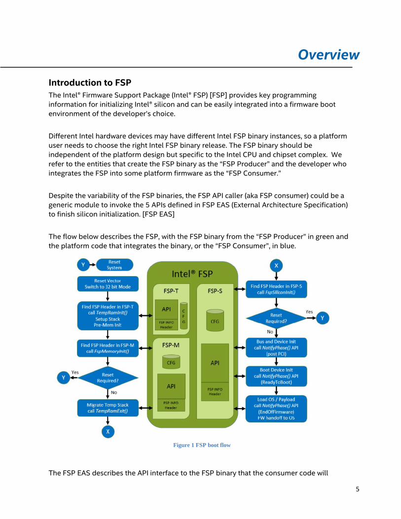
Introduction to FSP The Intel® Firmware Support Package (Intel® FSP) [FSP] provides key programming information for initializing Intel® silicon and can be easily integrated into a firmware boot environment of the developer’s choice.
Different Intel hardware devices may have different Intel FSP binary instances, so a platform user needs to choose the right Intel FSP binary release. The FSP binary should be independent of the platform design but specific to the Intel CPU and chipset complex. We refer to the entities that create the FSP binary as the “FSP Producer” and the developer who integrates the FSP into some platform firmware as the “FSP Consumer.”
Despite the variability of the FSP binaries, the FSP API caller (aka FSP consumer) could be a generic module to invoke the 5 APIs defined in FSP EAS (External Architecture Specification) to finish silicon initialization. [FSP EAS]
The flow below describes the FSP, with the FSP binary from the “FSP Producer” in green and the platform code that integrates the binary, or the “FSP Consumer”, in blue.
Figure 1 FSP boot flow
The FSP EAS describes the API interface to the FSP binary that the consumer code will

6
invoke, and it also describes the hand off state from the execution of the FSP binary. The latter information is conveyed in Hand-Off Blocks, or HOB’s. The FSP uses many of the data structures defined in the PI Specification including HOBs, Firmware Volumes, Firmware Files, etc.
The FSP binary can be integrated into any firmware solution, such as UEFI firmware (EDK2), or coreboot.
The topic of this paper is Intel FSP binary. We will discuss how to create Intel FSP binary (the producer) by using EDKII environment in more detail.
Introduction to FSP 2.0 FSP 1.x specification defines FSP APIs in one FSP binary. This is OK for SPI/NOR flash, because all the flash region can be mapped by the silicon during the system power on. However if the flash part is an NVMe/NAND flash, not all the flash region can be mapped during the system power on by default. The flash part has to be mapped step by step. For example, the first part – the TempRam (system SRAM or CPU cache) initialization code is mapped during the system power on. Then the second part – the memory initialization code is loaded to the TempRam by an early stage boot loader. Finally the third part – the silicon initialization code is loaded to the system DRAM by a later stage boot loader. FSP 1.x cannot support this model.
FSP 2.0 specification resolves this architecture limitation. The FSP binary may have multiple binary components:
FSP-T is for the TempRam initialization phase.
FSP-M is for the memory initialization phase.

7
FSP-S is for the silicon initialization phase.
Besides those standard components, FSP 2.0 specification also defines below optional components:
FSP-O for OEM extension component.
Figure 2 FSP component logical view
FSP 1.x specification defines AfterPciEnumeration and ReadyToBoot notify phase. However, some firmwares may enable some devices in PCI mode at BIOS phase and enable devices in ACPI mode at OS runtime phase. It need a hook point to switch the device mode. ReadyToBoot is still too early because these devices may stop working due to lack of driver in firmware phase if the device mode is switched. The proper place is ExitBootServices in UEFI firmware. FSP 2.0 defines EndOfFirmware notify phase to support this model switch.

8
FSP 1.x specification defines both VPD and UPD as configuration data. FSP2.0 simplifies the concept and regards all configuration data to be the UPD. A FSP consumer may copy the default UPD data, update it and pass the new data as the FSP API parameter to override the default one.
Introduction to EDKII EDKII is open source implementation for UEFI firmware, which can boot multiple UEFI OS. This document will introduce how to use EDKII as FSP producer module, to build an FSP binary.
Summary This section provided an overview of Intel FSP and EDKII.

9
FSP Produce/Consumer
In EDKII, there are 2 different FSP related packages. One is the producer, IntelFsp2Pkg, which is used to produce an FSP binary together with other EDKII core and silicon packages. The other is the consumer, IntelFsp2WrapperPkg, which will consume the FSP API’s exposed by the FSP binary.
Since FSP 2.0 specification is not backward compatible with the FSP 1.1 specification, IntelFspPkg and IntelFspWrapperPkg support is limited to FSP 1.1 specification and FSP 2.0 specification support is provided by separate IntelFsp2Pkg and IntelFsp2WrapperPkg.
This paper only focuses on how IntelFsp2Pkg creates an FSP binary. This paper will not describe on how IntelFsp2WrapperPkg consumes the FSP.bin, which is described in [FSP Consumer].
Figure 2 FSP producer/consumer
Summary This section describes the FSP producer/consumer in EDKII.

10
FSP infrastructure
Binary layout According to the FSP EAS, an FSP binary contains:
1) FSP_INFO_HEADER structure providing information about FSP.
It can be found in firmware section data of 1st firmware file in the FSP firmware volume.
2) Initialization code needed by the Intel silicon supported by the FSP.
The silicon initialization process is exposed by APIs defined in FSP_INFO_HEADER. For example, FSP_INFO_HEADER has offset of FspMemoryInit API. The caller can find the API offset and use C-style function to call FspMemoryInit, then FSP API completes the intended memory initialization and returns to the caller.
3) Configuration data region that allows the bootloader developer to customize some of
the settings.
The configuration region is exposed by CfgRegionOffset in FSP_INFO_HEADER.
Figure 3 FSP_INFO_HEADER layout

11
An FSP.bin may include FSP-T, FSP-M, and FSP-S. Each component has its own FSP_INFO_HEADER, code and configuration data region.
FSP runtime data structure Current FSP binary is built in a flash region and can be executed in flash region. On SPI NOR flash, those data can be accessed directly via MMIO. On NAND flash, those data must be loaded by other component. For example, the FSP-T is loaded by Initial Boot Loader; the FSP-M is loaded by an early loader; the FSP-S is loaded by a later loader.
In FSP_INFO_HEADER, (https://github.com/tianocore/edk2- IntelFsp2Pkg/tree/master/Include/FspInfoHeader.h) ImageBase is a pointer to FSP binary base address. CfgRegion is a pointer to configuration region. And the offsets for the 5 API entry points are also in the FSP header. (TempRamInit, NotifyPhase, FspMemoryInit, TempRamExit, FspSiliconInit). These entry points will be invoked during boot. (We will discuss detailed API flow in next section, and we will discuss how to build FSP_INFO_HEADER in “step 4 – Build with IntelFsp2Pkg”)
Each FSP module (FSP-T, FSP-M, FSP-S) contains its own configurable data region which will be used by the respective FSP component during initialization. This configuration region is a data structure called the Updateable Product Data (UPD) and will contain the default parameters for the FSP initialization.
The UPD parameters can be statically customized using a separate Binary Configuration Tool (BCT). There will be a Boot Setting File (BSF) [BSF] provided along with FSP binary to describe the configuration options within the FSP. This file contains the detailed information on all configurable options, including the description, the help information, the valid value range and the default value. (We will discuss the detail on how to expose the silicon configuration in “step 3 – Expose silicon configuration”)

12
During runtime, FspSecCore
Figure 4 FSP runtime data structure

13
(https://github.com/tianocore/edk2/tree/master/IntelFsp2Pkg/FspSecCore) will setup an FSP Global Data. The Global Data area contains below important data structures:
1) CoreStack – This is the context stack used by FSP. The context includes all general purpose registers, so that the FSP API can do a SetJump/LongJump-like context switch to the original FSP API caller provided stack, from the FSP internal stack.
2) PlatformData – This area records the Microcode and CodeCache region passed from TempRamInit API. Also an FSP specific implementation can save its own private data pointer to “DataPtr” field of PlatformData.
3) FspInfoHeader – This is a pointer to the FSP Information header. 4) TempRamInitUpdPtr , MemoryInitUpdPtr , SiliconInitUpdPtr – This is a pointer to the
user provided UPD region. It is used to override the default UPD data region in the FSP configuration area. If a caller provides the valid value for the UpdPtr, this new UPD will be used. If the UpdPtr is NULL, the FSP will consume the default UPD at the CfgRegion. Each FSP component should follow this way to put the default configuration data there.
5) API Index – This is the Index of FSP API 6) PerfData – This is used to record the performance data. Totally 32 entries are available.
The location of this Global Data area is recorded into PcdGlobalDataPointerAddress. (defined in https://github.com/tianocore/edk2/blob/master/IntelFsp2Pkg/IntelFsp2Pkg.dec) In most current platforms, it is an MMIO based scratch register.
FSP API Flow After the system power on, a bootloader finds FSP-T, and calls FSP TempRamInit API in the FspSecCore (https://github.com/tianocore/edk2/blob/master/IntelFsp2Pkg/FspSecCore/Ia32/FspApiEntryT.na sm), before the memory and stack are available. This FSP API loads the microcode, enables the code caching for a region specified by the bootloader and sets up a temporary stack to be used prior to the main memory being initialized.
Then the bootloader sets up a stack in temporary ram, runs C code, finds FSP-M and calls FspMemoryInit API. (https://github.com/tianocore/edk2/blob/master/IntelFsp2Pkg/FspSecCore/Ia32/FspApiEntryM.n asm ) After the FspMemoryInit API initializes the memory subsystem, it gives control back to the bootloader and let the bootloader migrate its own stack and heap data from the temporary ram to the system memory. Then the bootloader finds FSP-S and calls TempRamExit API to teardown the temporary ram set up by TempRamInit API.
Since FSP needs to return to the caller after FspMemoryInit, this work must be done in a platform defined MemoryDiscoveredPpiNotifyCallback() function. This function does switch stack back to the bootloader after the memory initialization done. After the bootloader calls 2nd API - TempRamExit in the SecCore, this API switches back to MemoryDiscoveredPpiNotifyCallback, runs the next instruction to reset cache, and switches back to the bootloader again.
Finally, the bootloader finds FSP-S and calls FspSiliconInit API

14
(https://github.com/tianocore/edk2/blob/master/IntelFsp2Pkg/FspSecCore/Ia32/FspApiEntryS.na sm) to initialize the processor and the chipset including the IO controllers in the chipset to enable normal operation of these devices.
Inside of FSP, FspNotifyPhase (https://github.com/tianocore/edk2/tree/master/IntelFsp2Pkg/FspNotifyPhase) reinstalls DXE_IPL PPI. After the PeiCore finishes dispatching all PEIM, it calls into FspNotifyPhase. Then FspNotifyPhase installs EndOfPei PPI, it means FSP initialization is done. Then FspNotifyPhase uses switch stack to 1) save current execution context, 2) jump back to the bootloader stack, and return to the bootloader.
Then the bootloader continues the device and bus initialization, and notifies NotifyPhase FSP API on AfterPciEnumeration, ReadyToBoot, and EndOfFirmware phase. The entrypoint of NotifyPhase API is still in FspSecCore, and it uses switch stack again, to 1) save caller context, 2) jump to previous context –FspNotifyPhase. Then FspNotifyPhase continues running code to notify silicon module on AfterPciEnumeration, ReadyToBoot, and EndOfFirmware.
Figure 5 FSP API Flow
Summary This section has a generic overview of FSP binary infrastructure, including the FSP binary layout, the runtime data structure, and the API flow for FSP 2.0.
In next sections, we will discuss the detail step by step on how to create a FSP binary and release it.

15
Step 1 – Put silicon initialization module to PI PEI
Silicon code V.S. Generic code V.S. Platform code Since an FSP is for silicon initialization, so the first step is to find what and where is silicon code.
There is one way to identify silicon code. If the code is written according to Intel silicon external design specification, most likely it is silicon code. For example, MemoryInit, CpuInit, SmartTimer, and Smbus are the silicon code. The silicon code might need rewritten if the silicon hardware is upgraded. And it should be same if only platform or board is changed.
Generic code means the code can be used on almost all silicons or platforms. For example, PEI Core, PCI Bus, and USB bus are generic code.
Platform code is the code binding to the platform board hardware. For example, GPIO setting and ACPI table are the platform code. The platform code can also be the generic code used for some platforms, but not for all platforms. For example, we treat the EfiVariable and SetupBrowser drivers to be platform code, because an OEM platform may have its own way to manage UEFI variable and setup page on the screen.
Here for an FSP, we only focus on first category “silicon code”.
Silicon Initialization Module V.S. Silicon Function Module There are 2 types of silicon code – initialization module and function module.
Initialization module means the module to initialize the memory subsystem, the processor and the chipset including the IO controllers in the chipset to enable the normal operation of these devices. For example, MemoryInit and CpuInit are initialization modules. The code runs once. After initialization, the code is never used any more.
Function module means the module to provide the functionality of a chipset. For example, SmartTimer provides EFI_TIMER_ARCH_PROTOCOL service abstraction, SMBUS provides EFI_PEI_SMBUS2_PPI service abstraction. These services are always available in memory after they are provided.
Here for an FSP, we only focus on first category “silicon initialization module”.
Put silicon initialization module to PEI After we find out silicon initialization modules, we need put these modules into the PEI phase. For UEFI/PI BIOS, there might be some cases that the original initialization code is in the DXE phase. For example, part of Platform Control Hub (PCH) initialization and System

16
Agent (SA) initialization are in the DXE phase. If so, these modules must be ported from DXE to PEI.
Summary This section describes how to find the silicon initialization modules and put them into the PEI phase.

17
Step 2 – Expose silicon configuration
Expose configuration - UPD The silicon initialization might need some configuration or policy. For example, SMRAM TSEG size, or UART debug enable/disable. These data can be set in the FSP configuration region.
Each FSP module (FSP-T, FSP-M, FSP-S) contains its own configurable data region which will be used by the FSP during initialization. This configuration region is a data structure called the Updateable Product Data (UPD) and will contain the default parameters for the FSP initialization.
The UPD parameters can be statically customized using a separate Binary Configuration Tool (BCT). There will be a Boot Setting File (BSF) provided along with the FSP binary to describe the configuration options within the FSP. This file contains the detailed information on all configurable options, including the description, the help information, the valid value range and the default value.
The UPD data can also be dynamically over ridden by the bootloader during runtime in addition to the static configuration. In most cases, if a configuration can be set by an end user via a bootloader setup page, it should be dynamically overridden in the UPD region. For example, SMRAM TSEG size can be changed from 8M to 16M by a user for validation purposes.
The UPD data is organized as a structure. The TempRamInit(), FspMemoryInit() and FspSiliconInit() API parameters include a pointer which can be initialized to point to the UPD data structure. If this pointer is initialized to NULL when these APIs are called, the FSP will use the default built-in UPD configuration data in the respective FSP components. However, if the bootloader needs to update any of the UPD parameters, it is recommended to copy the whole UPD structure from the FSP component to memory, update the parameters and initialize the UPD pointer to the address of the updated UPD structure. The FSP API will then use this data structure instead of the default configuration region data for the platform initialization. The UPD data structure is a project specific structure. Please refer to the Integration Guide for the details of this structure.
Below is an example of UPD configuration.
PlatformFsp.dsc: ====================================== [PcdsDynamicVpd.Upd]
# Global definitions in BSF # !BSF PAGES:{KBL:"Silicon System Agent", MRC:"Memory Reference Code", SPT:"PCH"} # !BSF BLOCK:{NAME:"XXX Platform", VER:"0.1"}
# !BSF FIND:{KBLUPD_T} # !HDR COMMENT:{FSP_UPD_HEADER:FSP UPD Header} # !HDR EMBED:{FSP_UPD_HEADER:FspUpdHeader:START} # FsptUpdSignature: {KBLFSP_T} gSiliconFspPkgTokenSpaceGuid.Signature | 0x0000 | 0x08 | 0x545F4450554C424B

18
gSiliconFspPkgTokenSpaceGuid.Revision | 0x0008 | 0x01 | 0x00 # !HDR EMBED:{FSP_UPD_HEADER:FspUpdHeader:END}
# !HDR COMMENT:{FSPT_CORE_UPD:Fsp T Core UPD}
# !HDR EMBED:{FSPT_CORE_UPD:FsptCoreUpd:START} # Base address of the microcode region. gSiliconFspPkgTokenSpaceGuid.MicrocodeRegionBase | 0x0020 | 0x04 | 0x00000000
# Length of the microcode region. gSiliconFspPkgTokenSpaceGuid.MicrocodeRegionSize | 0x0024 | 0x04 | 0x00000000
# !HDR EMBED:{FSPT_CORE_UPD:FsptCoreUpd:END}
......
################################################################################ # # UPDs consumed in FspMemoryInit Api # ################################################################################ # !BSF FIND:{KBLUPD_M} # !HDR COMMENT:{FSP_UPD_HEADER:FSP UPD Header} # !HDR EMBED:{FSP_UPD_HEADER:FspUpdHeader:START} # FspmUpdSignature: {KBLUPD_M} gSiliconFspPkgTokenSpaceGuid.Signature | 0x0000 | 0x08 | 0x4D5F4450554C424B gSiliconFspPkgTokenSpaceGuid.Revision | 0x0008 | 0x01 | 0x00 # !HDR EMBED:{FSP_UPD_HEADER:FspUpdHeader:END}
# !HDR COMMENT:{FSPM_ARCH_UPD:Fsp M Architecture UPD} # !HDR EMBED:{FSPM_ARCH_UPD:FspmArchUpd:START} gSiliconFspPkgTokenSpaceGuid.Revision | 0x0020 | 0x01 | 0x01
# !HDR STRUCT:{VOID *} gSiliconFspPkgTokenSpaceGuid.NvsBufferPtr | 0x0024 | 0x04 | 0x00000000
# !HDR STRUCT:{VOID *} gSiliconFspPkgTokenSpaceGuid.StackBase | 0x0028 | 0x04 | 0x00000000
gSiliconFspPkgTokenSpaceGuid.StackSize | 0x002C | 0x04 | 0x00000000
gSiliconFspPkgTokenSpaceGuid.BootLoaderTolumSize | 0x0030 | 0x04 | 0x00000000
gSiliconFspPkgTokenSpaceGuid.BootMode | 0x0034 | 0x04 | 0x00
# !HDR EMBED:{FSPM_ARCH_UPD:FspmArchUpd:END}
# !HDR COMMENT:{FSP_M_CONFIG:Fsp M Configuration} # !HDR EMBED:{FSP_M_CONFIG:FspmConfig:START} # !BSF PAGE:{MRC} # !BSF NAME:{Platform Reserved Memory Size} TYPE:{Combo} # !BSF OPTION:{0x400000 : 0x400000} # !BSF HELP:{The minimum platform memory size required to pass control into DXE} gPlatformFspPkgTokenSpaceGuid.PlatformMemorySize | 0x0040 | 0x08 | 0x400000
# !BSF NAME:{Tseg Size} TYPE:{Combo} # !BSF OPTION:{0x0400000:4MB, 0x01000000:16MB} # !BSF HELP:{Size of SMRAM memory reserved. 0x400000 for Release build and 0x1000000 for Debug
build} !if $(TARGET) == DEBUG
gSiliconFspPkgTokenSpaceGuid.TsegSize | 0x009C | 0x04 | 0x01000000 !else gSiliconFspPkgTokenSpaceGuid.TsegSize | 0x009C | 0x04 | 0x0400000
!endif ......
################################################################################ # # UPDs consumed in FspSiliconInit Api # ################################################################################ # !BSF FIND:{KBLUPD_S}

19
# !HDR COMMENT:{FSP_UPD_HEADER:FSP UPD Header} # !HDR EMBED:{FSP_UPD_HEADER:FspUpdHeader:START} # FspsUpdSignature: {KBLUPD_S}
gSiliconFspPkgTokenSpaceGuid.Signature | 0x0000 | 0x08 | 0x535F4450554C424B gSiliconFspPkgTokenSpaceGuid.Revision | 0x0008 | 0x01 | 0x00 # !HDR EMBED:{FSP_UPD_HEADER:FspUpdHeader:END} gSiliconFspPkgTokenSpaceGuid.Reserved | 0x0009 | 0x17 | {0x00}
# !HDR COMMENT:{FSP_S_CONFIG:Fsp S Configuration} # !HDR EMBED:{FSP_S_CONFIG:FspsConfig:START} # !BSF PAGE:{SKL} # !BSF NAME:{Logo Pointer} TYPE:{Combo} # !BSF OPTION:{0 : 0} # !BSF HELP:{Points to PEI Display Logo Image} gSiliconFspPkgTokenSpaceGuid.LogoPtr | 0x0020 | 0x04 | 0x00000000
# !BSF NAME:{Logo Size} TYPE:{Combo} # !BSF OPTION:{0 : 0} # !BSF HELP:{Size of PEI Display Logo Image} gSiliconFspPkgTokenSpaceGuid.LogoSize | 0x0024 | 0x04 | 0x00000000
# !BSF NAME:{Graphics Configuration Ptr} TYPE:{Combo} # !BSF OPTION:{0 : 0} # !BSF HELP:{Points to VBT} gSiliconFspPkgTokenSpaceGuid.GraphicsConfigPtr | 0x0028 | 0x04 | 0x00000000
# !HDR EMBED:{FSP_S_CONFIG:FspsConfig:END} gSiliconFspPkgTokenSpaceGuid.ReservedFspsUpd | 0x0770 | 0xD | {0x00}
======================================
Finally, in the FDF file, each FSP components includes its own configuration data. PlatformFsp.fdf: ====================================== [FV.FSP-T] FILE RAW = $(FSP_T_UPD_FFS_GUID) {
SECTION RAW = $(OUTPUT_DIRECTORY)/$(TARGET)_$(TOOL_CHAIN_TAG)/FV/$(FSP_T_UPD_TOOL_GUID).bin } [FV.FSP-M] FILE RAW = $(FSP_M_UPD_FFS_GUID) {
SECTION RAW = $(OUTPUT_DIRECTORY)/$(TARGET)_$(TOOL_CHAIN_TAG)/FV/$(FSP_M_UPD_TOOL_GUID).bin } [FV.FSP-S] FILE RAW = $(FSP_S_UPD_FFS_GUID) {
SECTION RAW = $(OUTPUT_DIRECTORY)/$(TARGET)_$(TOOL_CHAIN_TAG)/FV/$(FSP_S_UPD_TOOL_GUID).bin }
======================================
Prebuild - GenCfgOpt After the UPD is defined in the dsc file, the GenCfgOpt.py tool (https://github.com/tianocore/edk2/blob/master/IntelFsp2Pkg/Tools/GenCfgOpt.py ) will create the corresponding UDP header file for the boot loader developer.
1) Generate PCD information text file. ====================================== python %WORKSPACE%/IntelFsp2Pkg/Tools/GenCfgOpt.py UPDTXT ^
%WORKSPACE%\%FSP_PKG_NAME%\%FSP_PKG_NAME%.dsc ^ %WORKSPACE%\%OUT_DIR%\%FSP_PKG_NAME%\%BD_TARGET%_%TOOL_CHAIN_TAG%\FV ^ %WORKSPACE%\%FSP_PKG_NAME%\%FSP_PKG_NAME%Config.dsc ^ %WORKSPACE%\%FSP_PKG_NAME%\%FSP_PKG_NAME%ExtConfig.dsc ^ %BD_MACRO%
======================================

20
2) Convert the PCD information text file to binary. ====================================== %WORKSPACE%\BaseTools\Bin\Win32\BPDG.exe ^
%WORKSPACE%\%OUT_DIR%\%FSP_PKG_NAME%\%BD_TARGET%_%TOOL_CHAIN_TAG%\FV\%FSP_T_UPD_GUID%.txt ^ -o %WORKSPACE%\%OUT_DIR%\%FSP_PKG_NAME%\%BD_TARGET%_%TOOL_CHAIN_TAG%\FV\%FSP_T_UPD_GUID%.bin ^ -m %WORKSPACE%\%OUT_DIR%\%FSP_PKG_NAME%\%BD_TARGET%_%TOOL_CHAIN_TAG%\FV\%FSP_T_UPD_GUID%.map
%WORKSPACE%\BaseTools\Bin\Win32\BPDG.exe ^
%WORKSPACE%\%OUT_DIR%\%FSP_PKG_NAME%\%BD_TARGET%_%TOOL_CHAIN_TAG%\FV\%FSP_M_UPD_GUID%.txt ^ -o %WORKSPACE%\%OUT_DIR%\%FSP_PKG_NAME%\%BD_TARGET%_%TOOL_CHAIN_TAG%\FV\%FSP_M_UPD_GUID%.bin ^ -m %WORKSPACE%\%OUT_DIR%\%FSP_PKG_NAME%\%BD_TARGET%_%TOOL_CHAIN_TAG%\FV\%FSP_M_UPD_GUID%.map
%WORKSPACE%\BaseTools\Bin\Win32\BPDG.exe ^
%WORKSPACE%\%OUT_DIR%\%FSP_PKG_NAME%\%BD_TARGET%_%TOOL_CHAIN_TAG%\FV\%FSP_S_UPD_GUID%.txt ^ -o %WORKSPACE%\%OUT_DIR%\%FSP_PKG_NAME%\%BD_TARGET%_%TOOL_CHAIN_TAG%\FV\%FSP_S_UPD_GUID%.bin ^ -m %WORKSPACE%\%OUT_DIR%\%FSP_PKG_NAME%\%BD_TARGET%_%TOOL_CHAIN_TAG%\FV\%FSP_S_UPD_GUID%.map
======================================
3) Generate the .h UPD header file. ======================================
python %WORKSPACE%/IntelFsp2Pkg/Tools/GenCfgOpt.py HEADER ^
%WORKSPACE%\%FSP_PKG_NAME%\%FSP_PKG_NAME%.dsc ^ %WORKSPACE%\%OUT_DIR%\%FSP_PKG_NAME%\%BD_TARGET%_%TOOL_CHAIN_TAG%\FV ^ %WORKSPACE%\%FSP_PKG_NAME%\Include\BootLoaderPlatformData.h ^ %WORKSPACE%\%FSP_PKG_NAME%\%FSP_PKG_NAME%Config.dsc ^ %WORKSPACE%\%FSP_PKG_NAME%\%FSP_PKG_NAME%ExtConfig.dsc ^ %BD_MACRO%
4) Generate a FSP BSF file. ====================================== python %WORKSPACE%/IntelFsp2Pkg/Tools/GenCfgOpt.py GENBSF ^
%WORKSPACE%\%FSP_PKG_NAME%\%FSP_PKG_NAME%.dsc ^ %WORKSPACE%\%OUT_DIR%\%FSP_PKG_NAME%\%BD_TARGET%_%TOOL_CHAIN_TAG%\FV ^ %WORKSPACE%\%FSP_BIN_PKG_NAME%\Fsp.bsf ^ %WORKSPACE%\%FSP_PKG_NAME%\%FSP_PKG_NAME%Config.dsc ^ %WORKSPACE%\%FSP_PKG_NAME%\%FSP_PKG_NAME%ExtConfig.dsc ^ %BD_MACRO%
======================================
The content in FSP UPD header file is similar to the below: FsptUpd.h: ====================================== typedef struct {
UINT32 MicrocodeRegionBase; UINT32 MicrocodeRegionSize;
...... } FSPT_CORE_UPD; typedef struct {
FSP_UPD_HEADER FspUpdHeader; FSPT_CORE_UPD FsptCoreUpd;
...... } FSPT_UPD; ======================================

21
FspmUpd.h:
====================================== typedef struct {
UINT64 PlatformMemorySize; UINT32 TsegSize;
...... } FSP_M_CONFIG; typedef struct {
FSP_UPD_HEADER FspUpdHeader; FSPM_ARCH_UPD FspmArchUpd; FSP_M_CONFIG FspmConfig;
...... } FSPM_UPD; ====================================== FspsUpd.h: ====================================== typedef struct {
UINT32 LogoPtr; UINT32 LogoSize; UINT32 GraphicsConfigPtr;
...... } FSP_S_CONFIG; typedef struct {
FSP_UPD_HEADER FspUpdHeader; FSP_S_CONFIG FspsConfig;
...... } FSPS_UPD; ======================================
This GenCfgOpt.py tool runs before the formal EDKII build. That is why we call it as a pre- build tool.
For the more detail, please refer to the user manual (https://github.com/tianocore/edk2/blob/master/IntelFsp2Pkg/Tools/UserManuals/GenCfgOptUs erManual.docx )
Figure 7 Prebuild tool – GenCfgOpt.py
User configuration - BSF/BCT The GenCfgOpt.py tool also creates a BSF configuration file [BSF] so that a user can use a BCT tool (www.intel.com/fsp) to do the configuration after an FSP binary is generated.

22
The content in BSF file is like below. FSP.bsf: ====================================== /* UPD data region*/ Find "FSPM_UPD" Skip XX bytes $gPlatformFspPkgTokenSpaceGuid_PlatformMemorySize 8 bytes
$_DEFAULT_ = 0x400000 $gSiliconFspPkgTokenSpaceGuid_TsegSize 4 bytes
$_DEFAULT_ = 0x0400000 ......
Find "FSPS_UPD" Skip XX bytes $gSiliconFspPkgTokenSpaceGuid_LogoPtr 4 bytes
$_DEFAULT_ = 0x00000000 $gSiliconFspPkgTokenSpaceGuid_LogoSize 4 bytes
$_DEFAULT_ = 0x00000000 $gSiliconFspPkgTokenSpaceGuid_GraphicsConfigPtr 4 bytes
$_DEFAULT_ = 0x00000000 ...... /* Show configuration */ Page “Memory Reference Code"
Combo $gPlatformFspPkgTokenSpaceGuid_PlatformMemorySize, "Platform Reserved Memory Size", &gPlatformFspPkgTokenSpaceGuid_PlatformMemorySize,
Help "The minimum platform memory size required to pass control into DXE"
Combo $gSiliconFspPkgTokenSpaceGuid_TsegSize, "Tseg Size", &gSiliconFspPkgTokenSpaceGuid_TsegSize,
Help "Size of SMRAM memory reserved. 0x400000 for Release build and 0x1000000 for Debug build" Page "Silicon System Agent"
Combo $gSiliconFspPkgTokenSpaceGuid_LogoPtr, "Logo Pointer", &gSiliconFspPkgTokenSpaceGuid_LogoPtr,
Help "Points to PEI Display Logo Image" Combo $gSiliconFspPkgTokenSpaceGuid_LogoSize, "Logo Size",
&gSiliconFspPkgTokenSpaceGuid_LogoSize, Help "Size of PEI Display Logo Image"
Combo $gSiliconFspPkgTokenSpaceGuid_GraphicsConfigPtr, "Graphics Configuration Ptr", &gSiliconFspPkgTokenSpaceGuid_GraphicsConfigPtr,
Help "Points to VBT" ...... ======================================
Summary This section describes how to use the UPD infrastructure to expose the silicon configuration in an FSP package.

23
Step 3 – Build with IntelFsp2Pkg
The FSP leverages the build process of the EDK2 firmware. The FSP binary is built as a Firmware Device (FD) and requires a DSC and FDF files that the EDK2 build process uses to build the FSP.
The FSP binary includes silicon modules, FspSecCore and FspNotifyPhase in IntelFsp2Pkg. (https://github.com/tianocore/edk2/tree/master/IntelFsp2Pkg ). In addition to these, the FSP should include below components to make it to be a full solution.
FSP Description File The FSP binary may optionally include an FSP description file. This file will provide the information about the FSP, including the information about different silicon revisions the FSP supports. See below sample in FDF file.
PlatformFspPkg.fdf: ====================================== [FV.FSP-M] # # Description file # INF RuleOverride = FSPHEADER $(FSP_PACKAGE)/FspHeader/FspHeader.inf ======================================
FSP_INFO_HEADER The FSP_INFO_HEADER must be the 1st firmware file within the FSP firmware volume. We can use the method below as a way to ensure that layout.
First, we define a FSP_INFO_HEADER structure in a C style file and use .ASLC as file name extension. We must define a ReferenceAcpiTable() function referring to this global data structure, or this global data will be optimized at link phase. We also need FSP_INFO_EXTENDED_HEADER for FSP2.0.
FSP_PATCH_TABLE is an FSP implementation specific table. It is put here because we want to reserve space in the FSP binary to let the platform refer to the patch information.
FspHeader.aslc: ====================================== typedef struct{
FSP_INFO_HEADER FspInfoHeader; FSP_INFO_EXTENDED_HEADER FspInfoExtendedHeader; FSP_DATA_TABLE FspDataTable; FSP_PATCH_TABLE FspPatchTable; UINT32 PatchData[1];
}TABLES; TABLES mTable = {

24
{ // FspInfoHeader FSP_INFO_HEADER_SIGNATURE, // UINT32 Signature (FSPH) sizeof(FSP_INFO_HEADER), // UINT32 HeaderLength; {0x00, 0x00, 0x00}, // UINT8 Reserved1[3]; FixedPcdGet8(PcdFspHeaderRevision), // UINT8 HeaderRevision; FixedPcdGet32(PcdFspImageRevision), // UINT32 ImageRevision;
UINT64_TO_BYTE_ARRAY( FixedPcdGet64(PcdFspImageIdString)), // CHAR8 ImageId[8];
FixedPcdGet32(PcdFspAreaSize), // UINT32 ImageSize; FixedPcdGet32(PcdFspAreaBaseAddress), // UINT32 ImageBase;
FixedPcdGet16(PcdFspImageAttributes), // UINT16 ImageAttribute; FixedPcdGet16(PcdFspComponentAttributes),// UINT16 ComponentAttribute; 0x12345678, // UINT32 CfgRegionOffset; 0x12345678, // UINT32 CfgRegionSize; 0x00000000, // UINT32 Reserved2;
0x00000000, // UINT32 NemInitEntry; 0x00000000, // UINT32 Reserved3; 0x00000000, // UINT32 NotifyPhaseEntry; 0x00000000, // UINT32 FspMemoryInitEntry; 0x00000000, // UINT32 TempRamExitEntry; 0x00000000, // UINT32 FspSiliconInitEntry;
}, { // FspExtendedHeader
FSP_INFO_EXTENDED_HEADER_SIGNATURE, // UINT32 Signature (FSPE) sizeof(FSP_INFO_EXTENTED_HEADER), // UINT32 Length; FSPE_HEADER_REVISION_1, // UINT8 Revision; 0x00, // UINT8 Reserved; {FSP_PRODUCER_ID}, // CHAR8 FspProducerId[6]; 0x00000001, // UINT32 FspProducerRevision; 0x00000000, // UINT32 FspProducerDataSize;
}, {
FSP_DATA_SIGNATURE, // UINT32 Signature (FSPD) sizeof(FSP_DATA_TABLE), // UINT32 Length; FixedPcdGet32(PcdFlashFvFsptBase), // UINT32 FsptBase; FixedPcdGet32(PcdFlashFvFspmBase), // UINT32 FspmBase; FixedPcdGet32(PcdFlashFvFspsBase), // UINT32 FspsBase;
}, { // FspPatchTable
FSP_FSPP_SIGNATURE, // UINT32 Signature (FSPP) sizeof(FSP_PATCH_TABLE), // UINT16 HeaderLength; FSPP_HEADER_REVISION_1, // UINT8 HeaderRevision; 0x00, // UINT8 Reserved; 1, // UINT32 PatchEntryNum;
}, {0xFFFFFFFC} // UINT32 Patch FVBASE at end of FV
}; VOID* ReferenceAcpiTable ( VOID )

25
{ // // Reference the table being generated to prevent the optimizer from // removing the data structure from the executable // return (VOID*)&mTable;
} ======================================
After that we need create an INF file and use the USER_DEFINED as the MODULE_TYPE. FspHeader.inf ======================================
MODULE_TYPE = USER_DEFINED ======================================
Then we add this module in FDF file as first module of FSP FV, and use build rule override FSPHEADER to extract the global data section only. PlatformFspPkg.fdf: ====================================== [FV.FSP-T] INF RuleOverride = FSPHEADER $(FSP_PACKAGE)/FspHeader/FspHeader.inf [FV.FSP-M] INF RuleOverride = FSPHEADER $(FSP_PACKAGE)/FspHeader/FspHeader.inf [FV.FSP-S] INF RuleOverride = FSPHEADER $(FSP_PACKAGE)/FspHeader/FspHeader.inf [Rule.Common.USER_DEFINED.FSPHEADER]
FILE RAW = $(NAMED_GUID) { RAW BIN |.acpi
} ======================================
Convert UPD to Policy Then we need a platform module to the convert UPD data to the silicon policy PPI. The UPD data pointer is saved to ApiParameter in FspCommonLib SetFspApiParameter(). Then a platform may use GetFspApiParameter() to get the UPD data pointer.
(https://github.com/tianocore/edk2/blob/master/IntelFsp2Pkg/Include/Library/FspCommonLib.h )
Some sample code to consume GetFspApiParameter () below: ====================================== EFI_STATUS FspInitPreMemEntryPoint (
IN EFI_PEI_FILE_HANDLE FileHandle, IN CONST EFI_PEI_SERVICES **PeiServices )
{ FspmUpdDataPtr = (FSPM_UPD *) GetFspApiParameter (); FspUpdatePeiPchPolicyPreMem (SiPreMemPolicyPpi, FspmUpdDataPtr); FspUpdatePeiCpuPolicyPreMem (SiPreMemPolicyPpi, FspmUpdDataPtr);

26
FspUpdatePeiSaPolicyPreMem (SiPreMemPolicyPpi, FspmUpdDataPtr); }
EFI_STATUS FspInitEntryPoint (
IN EFI_PEI_FILE_HANDLE FileHandle, IN CONST EFI_PEI_SERVICES **PeiServices )
{ FspsUpd = (FSPS_UPD *)GetFspApiParameter (); FspUpdatePeiPchPolicy (SiPolicyPpi, FspsUpd); FspUpdatePeiCpuPolicy (SiPolicyPpi, FspsUpd); FspUpdatePeiSaPolicy (SiPolicyPpi, FspsUpd);
} ======================================
MemoryDiscoveredPpiNotifyCallback for FSP 2.0 In FSP 2.0, we need use the Pei2LoaderSwitchStack API defined in the FspSwitchStackLib. (https://github.com/tianocore/edk2/blob/master/IntelFsp2Pkg/Include/Library/FspSwitchStackLi
b.h ) to switch back to the bootloader.
Some sample code for MemoryDiscoveredPpiNotifyCallback() can be found below: ======================================
EFI_STATUS ReportAndInstallNewFv (
VOID )
{ EFI_FIRMWARE_VOLUME_EXT_HEADER *FwVolExtHeader; FSP_INFO_HEADER *FspInfoHeader; EFI_FIRMWARE_VOLUME_HEADER *FvHeader; UINT8 *CurPtr; UINT8 *EndPtr;
FspInfoHeader = GetFspInfoHeaderFromApiContext(); if (FspInfoHeader->Signature != FSP_INFO_HEADER_SIGNATURE) {
DEBUG ((DEBUG_ERROR, "The signature of FspInfoHeader getting from API context is invalid.\n"));
FspInfoHeader = GetFspInfoHeader(); }
CurPtr = (UINT8 *)FspInfoHeader->ImageBase; EndPtr = CurPtr + FspInfoHeader->ImageSize - 1;
while (CurPtr < EndPtr) {
FvHeader = (EFI_FIRMWARE_VOLUME_HEADER *)CurPtr; if (FvHeader->Signature != EFI_FVH_SIGNATURE) {
break; }
if (FvHeader->ExtHeaderOffset != 0) {
// // Searching for the silicon FV in the FSP image. // FwVolExtHeader = (EFI_FIRMWARE_VOLUME_EXT_HEADER *) ((UINT8 *) FvHeader + FvHeader-
>ExtHeaderOffset); if (CompareGuid(&FwVolExtHeader->FvName, &gFspSiliconFvGuid)) {
PeiServicesInstallFvInfoPpi ( NULL, (VOID *)FvHeader, (UINTN) FvHeader->FvLength, NULL,

27
NULL );
} } CurPtr += FvHeader->FvLength;
}
return EFI_SUCCESS; }
EFI_STATUS EFIAPI MemoryDiscoveredPpiNotifyCallback (
IN EFI_PEI_SERVICES **PeiServices, IN EFI_PEI_NOTIFY_DESCRIPTOR *NotifyDescriptor, IN VOID *Ppi )
{
DEBUG ((DEBUG_INFO | DEBUG_INIT, "Memory Discovered Notify invoked ...\n"));
......
// // Migrate BootLoader data before destroying CAR // FspMigrateTemporaryMemory ();
// // Calling use FspMemoryInit API // Return the control directly // HobListPtr = (VOID **)GetFspApiParameter2 (); if (HobListPtr != NULL) {
*HobListPtr = (VOID *)GetHobList (); }
// // This is the end of the FspMemoryInit API // Give control back to the boot loader // DEBUG ((DEBUG_INFO | DEBUG_INIT, "FspMemoryInitApi() - End\n"));
SetFspApiReturnStatus (EFI_SUCCESS); Pei2LoaderSwitchStack ();
if (GetFspApiCallingIndex () == TempRamExitApiIndex) {
// // Disable CAR and resets fixed and variable MTRR values. // ResetCacheAttributes ();
// // This is the end of the TempRamExit API // Give control back to the boot loader // DEBUG ((DEBUG_INFO | DEBUG_INIT, "TempRamExitApi() - End\n"));
SetFspApiReturnStatus (EFI_SUCCESS); Pei2LoaderSwitchStack ();
}
// // MTRRs are not already programmed in FSP. // if (!CheckIfMtrrsProgrammed ()) {
ProgramCacheAttributes (); DEBUG ((DEBUG_INFO | DEBUG_INIT, "MTRR programming:\n")); PrintMtrrs ();
}

28
// // Install FSP silicon FV // ReportAndInstallNewFv ();
DEBUG ((DEBUG_INFO | DEBUG_INIT, "Memory Discovered Notify completed ...\n"));
}
======================================
Notify Phase Once the boot loader calls the FSP NotifyPhaseApi, the FspNotifyPhase PEIM, BaseFspPlatformLib, FspNotificationHandler() (https://github.com/tianocore/edk2/blob/master/IntelFsp2Pkg/Library/BaseFspPlatformLib/FspPl atformNotify.c ) will install the corresponding PPI (gEfiPciEnumerationCompleteProtocolGuid, gEfiEventReadyToBootGuid, gFspEventEndOfFirmwareGuid) to notify all the PEIMs. The silicon code may register some PPI notifications to handle the final silicon initialization.
Postbuild - PatchFv Finally, an FSP.FD will be generated. But it is not enough. We need patch the pointer referenceded in the binary.
1) Patch FSP-T
====================================== echo Patch FSP-T Image ... python %WORKSPACE%\IntelFsp2Pkg\Tools\PatchFv.py ^
%WORKSPACE%\%OUT_DIR%\%FSP_PKG_NAME%\%BD_TARGET%_%TOOL_CHAIN_TAG%\FV ^ FSP-T:KBLFSP ^ "0x0000, _BASE_FSP-T_,
@Temporary Base" ^ "<[0x0000]>+0x00AC, [<[0x0000]>+0x0020],
@FSP-T Size" ^ "<[0x0000]>+0x00B0, [0x0000],
@FSP-T Base" ^ "<[0x0000]>+0x00B4, ([<[0x0000]>+0x00B4] & 0xFFFFFFFF) | 0x0001,
@FSP-T Image Attribute" ^ "<[0x0000]>+0x00B6, ([<[0x0000]>+0x00B6] & 0xFFFF0FFC) | 0x1000 | %FSP_BUILD_TYPE%
| %FSP_RELEASE_TYPE%, @FSP-T Component Attribute" ^ "<[0x0000]>+0x00B8, 70BCF6A5-FFB1-47D8-B1AE-EFE5508E23EA:0x1C - <[0x0000]>,
@FSP-T CFG Offset" ^ "<[0x0000]>+0x00BC, [70BCF6A5-FFB1-47D8-B1AE-EFE5508E23EA:0x14] & 0xFFFFFF - 0x001C,
@FSP-T CFG Size" ^ "<[0x0000]>+0x00C4, FspSecCoreT:_TempRamInitApi - [0x0000],
@TempRamInit API" ^ "0x0000, 0x00000000,
@Restore the value" ^ "FspSecCoreT:_FspInfoHeaderRelativeOff, FspSecCoreT:_AsmGetFspInfoHeader - {912740BE-2284-
4734-B971-84B027353F0C:0x1C}, @FSP-T Header Offset"
======================================
2) Patch FSP-M ====================================== echo Patch FSP-M Image ... python %WORKSPACE%\IntelFsp2Pkg\Tools\PatchFv.py ^
%WORKSPACE%\%OUT_DIR%\%FSP_PKG_NAME%\%BD_TARGET%_%TOOL_CHAIN_TAG%\FV ^ FSP-M:KBLFSP ^

29
"0x0000, _BASE_FSP-M_, @Temporary Base" ^
"<[0x0000]>+0x00AC, [<[0x0000]>+0x0020], @FSP-M Size" ^
"<[0x0000]>+0x00B0, [0x0000], @FSP-M Base" ^
"<[0x0000]>+0x00B4, ([<[0x0000]>+0x00B4] & 0xFFFFFFFF) | 0x0001, @FSP-M Image Attribute" ^
"<[0x0000]>+0x00B6, ([<[0x0000]>+0x00B6] & 0xFFFF0FFC) | 0x2000 | %FSP_BUILD_TYPE% | %FSP_RELEASE_TYPE%, @FSP-M Component Attribute" ^
"<[0x0000]>+0x00B8, D5B86AEA-6AF7-40D4-8014-982301BC3D89:0x1C - <[0x0000]>, @FSP-M CFG Offset" ^
"<[0x0000]>+0x00BC, [D5B86AEA-6AF7-40D4-8014-982301BC3D89:0x14] & 0xFFFFFF - 0x001C, @FSP-M CFG Size" ^
"<[0x0000]>+0x00D0, FspSecCoreM:_FspMemoryInitApi - [0x0000], @MemoryInitApi API" ^
"<[0x0000]>+0x00D4, FspSecCoreM:_TempRamExitApi - [0x0000], @TempRamExit API" ^
"FspSecCoreM:_FspPeiCoreEntryOff, PeiCore: ModuleEntryPoint - [0x0000], @PeiCore Entry" ^
"0x0000, 0x00000000, @Restore the value" ^
"FspSecCoreM:_FspInfoHeaderRelativeOff, FspSecCoreM:_AsmGetFspInfoHeader - {912740BE-2284- 4734-B971-84B027353F0C:0x1C}, @FSP-M Header Offset"
======================================
3) Patch FSP-S ====================================== echo Patch FSP-S Image ... python %WORKSPACE%\IntelFsp2Pkg\Tools\PatchFv.py ^
%WORKSPACE%\%OUT_DIR%\%FSP_PKG_NAME%\%BD_TARGET%_%TOOL_CHAIN_TAG%\FV ^ FSP-S:KBLFSP ^ "0x0000, _BASE_FSP-S_,
@Temporary Base" ^ "<[0x0000]>+0x00AC, [<[0x0000]>+0x0020],
@FSP-S Size" ^ "<[0x0000]>+0x00B0, [0x0000],
@FSP-S Base" ^ "<[0x0000]>+0x00B4, ([<[0x0000]>+0x00B4] & 0xFFFFFFFF) | 0x0001,
@FSP-S Image Attribute" ^ "<[0x0000]>+0x00B6, ([<[0x0000]>+0x00B6] & 0xFFFF0FFC) | 0x3000 | %FSP_BUILD_TYPE%
| %FSP_RELEASE_TYPE%, @FSP-S Component Attribute" ^ "<[0x0000]>+0x00B8, E3CD9B18-998C-4F76-B65E-98B154E5446F:0x1C - <[0x0000]>,
@FSP-S CFG Offset" ^ "<[0x0000]>+0x00BC, [E3CD9B18-998C-4F76-B65E-98B154E5446F:0x14] & 0xFFFFFF - 0x001C,
@FSP-S CFG Size" ^ "<[0x0000]>+0x00D8, FspSecCoreS:_FspSiliconInitApi - [0x0000],
@SiliconInit API" ^ "<[0x0000]>+0x00CC, FspSecCoreS:_NotifyPhaseApi - [0x0000],
@NotifyPhase API" ^ "0x0000, 0x00000000,
@Restore the value" ^ "FspSecCoreS:_FspInfoHeaderRelativeOff, FspSecCoreS:_AsmGetFspInfoHeader - {912740BE-2284-
4734-B971-84B027353F0C:0x1C}, @FSP-S Header Offset"
======================================
The FSP_INFO_HEADER data fields are patched in each FSP components. The FspInfoHeaderRelativeOff is the symbol in the FspSecCore.
(https://github.com/tianocore/edk2/blob/master/IntelFsp2Pkg/FspSecCore/Ia32/FspHelper.nasm ) It is used to calculate the FspBaseAddress.
This PatchFv.py tool runs after the formal EDKII build and it will patch the final FD binary. That is why we call it as postbuild tool.

30
For the more detail, please refer to the user manual (https://github.com/tianocore/edk2/blob/master/IntelFsp2Pkg/Tools/UserManuals/PatchFvUserM anual.docx )
Figure 8 Postbuild tool – PatchFv.py
Summary
This section describes the additional components and steps needed to build an FSP binary.

31
Step 4 – Release it
Package content Finally, the release package should include, but is not limited to:
1) Binary file – FSP.fd
2) Source header files – FspUpd.h, FsptUpd.h, FspmUpd.h, FspsUpd.h
3) Tool configuration file – FSP.bsf
4) Document - <Silicon>_FSP_Integration_Guide Congratulations!!!

32
Conclusion
The Firmware Support Package (FSP) provides a simple silicon initialization solution that reduces time-to-market, and it is economical to build. IntelFsp2Pkg is the core infrastructure of the FSP producer in EDKII to support building a FSP binary. This paper describes the detailed work flow and how to use IntelFsp2Pkg to build an FSP binary.

33
Glossary
ACPI – Advanced Configuration and Power Interface. Describe system configuration that is not discoverable and provide runtime interpreted capabilities
BCT – Binary Configuration Tool. The tool to patch FSP binary. BSF – Boot Setting File. The configuration file used by BCT tool. BFV – Boot Firmware Volume. See [UEFI PI Specification].
CAR – Cache-As-RAM. Use of the processor cache as a temporary memory / stack store DEC – EDKII Package Declaration File. See [EDKII specification]
DSC – EDKII Platform Description File. See [EDKII specification]
FD – EDKII Flash Device binary image, defined in FDF.
FDF – EDKII Flash Descirption File. See [EDKII specification]
FFS – firmware file system, describes the organization of files and (optionally) free space within the firmware volume. See [UEFI PI Specification]
FSP – Intel Firmware Support Package
FSP Consumer – the entity that integrates the FSP.bin, such as EDKII or other firmware like coreboot
FSP Producer – the entity that creates the FSP binary, such as the CPU and chipset manufacturer (e.g., “Silicon Vendor”).
Bootloader – another name for an “FSP Consumer”, as distinct from a MBR-based loader for PC/AT BIOS or the OS loader as a UEFI Executable for UEFI [UEFI Overview]
FV – Firmware Volume, a logical firmware device. See [UEFI PI Specification]. INF – EDKII Module Information File. See [EDKII specification]
PCD – Platform Configuration Database. See [UEFI PI Specification]. PI – Platform Initialization. Volume 1-5 of the UEFI PI specifications. SMM – System Management Mode. x86 CPU operational mode that is isolated from and transparent to the operating system runtime.

34
UEFI – Unified Extensible Firmware Interface. Firmware interface between the platform and the operating system.
UPD – Updatable Product Data. Configuration data region in FSP binary, which can only be configured statically for default value, but also can be overwritten during boot at runtime. See [FSP EAS]
VTF – Volume Top File, a file that must be located such that the last byte of the file is also the last byte of the firmware volume. See [UEFI PI Specification]
35
References
[ACPI] Advanced Configuration and Power Interface, vesion 6.0, www.uefi.org
[BSF] Boot Setting File (BSF) Specification https://firmware.intel.com/sites/default/files/BSF_1_0.pdf
[COREBOOT] coreboot firmware www.coreboot.org [EDK2] UEFI Developer Kit www.tianocore.org
[EDKII specification] A set of specification describe EDKII DEC/INF/DSC/FDF file format, as well as EDKII BUILD. http://tianocore.sourceforge.net/wiki/EDK_II_Specifications
[FSP] Intel Firmware Support Package http://www.intel.com/content/www/us/en/intelligent- systems/intel-firmware-support-package/intel-fsp-overview.html
[FSP EAS] FSP External Architecture Specification http://www.intel.com/content/www/us/en/embedded/software/fsp/fsp-architecture-spec-v2.html
[FSP Consumer] Yao, Zimmer, Rangarajan, Ma, Estrada, Mudusuru, “A_Tour_Beyond_BIOS_Using_the_Intel_Firmware_Support_Package_with_the_EFI_Develop er_Kit_II_(FSP2.0)” https://github.com/tianocore/tianocore.github.io/wiki/EDK-II-white-papers
[UEFI] Unified Extensible Firmware Interface (UEFI) Specification, Version 2.5 www.uefi.org
[UEFI Book] Zimmer,, et al, “Beyond BIOS: Developing with the Unified Extensible Firmware Interface,” 2nd edition, Intel Press, January 2011
[UEFI Overview] Zimmer, Rothman, Hale, “UEFI: From Reset Vector to Operating System,” Chapter 3 of Hardware-Dependent Software, Springer, February 2009
[UEFI PI Specification] UEFI Platform Initialization (PI) Specifications, volumes 1-5, Version
1.4 www.uefi.org

36
Authors
Jiewen Yao ([email protected]) is EDKII BIOS architect, EDKII FSP package maintainer with Software and Services Group (SSG) at Intel Corporation.
Vincent J. Zimmer ([email protected]) is a Senior Principal Engineer with the Software and Services Group (SSG) at Intel Corporation.
Giri Mudusuru ([email protected]) is BIOS architect and Principal Engineer in the Client Components Group (CCG) at Intel Corporation.
Satya P. Yarlagadda ([email protected]) is BIOS architect in the Client Components Group (CCG) at Intel Corporation.
Ravi P. Rangarajan ([email protected]) is BIOS architect in the Internet of Things (IOT) Group (IOTG) at Intel Corporation.
Maurice Ma ([email protected]) is BIOS architect in the Internet of Things (IOT) IOT Group (IOTG) at Intel Corporation.


![The Node.js API - SourceForgegromnitsky.users.sourceforge.net/js/nodejs/nodejs.pdfvi 5.4.64 buf.writeDoubleBE(value[, offset])::::: 76 5.4.65 buf.writeDoubleLE(value[, offset]):::::](https://img.pdfslide.net/doc/110x75/609f6a3d737262321b734dbd/the-nodejs-api-s-vi-5464-bufwritedoublebevalue-offset-76-5465.jpg)