Embed Size (px)
Citation preview
A TRANSMISSION LINE BALANCE TEST METER
by Lloyd Butler VK5BR with modifications by Phil Storr VK5SRP.Here is a simple meter to check the balance of currents running in the two legs of a transmission line. It can be used to check the balance of currents between the inner conductor and the outer coaxial conductor in a coax cable as well as between the legs of an open wire pair.
IntroductionA typical amateur radio antenna installation makes use of a simple dipole or other balanced form of antenna fed via a coaxial transmission line. Because the line is unbalanced, some form of unbalanced to balanced coupling is normally necessary between the coaxial line and the antenna. Without this coupling, a condition is set up where currents running in the inner and outer legs of the coax line are unbalanced and a common mode or longitudinal current component is developed along the length of the line, causing radiation from the line. Apart from distorting the radiation pattern inherent to the antenna proper, it encourages annoying induction into equipment and wiring within the radio shack as well as on receiving encouraging induction of vertically polarised near field noise.
A typical balancing interface is the choke balun which must have sufficient common mode rejection impedance to minimise the longitudinal current component. Whilst most radio amateurs possess an SWR meter which can be used in series with the coax line to check how well the antenna is matched to the 50 ohm line, it gives no indication that the currents running in the two legs of the line might be unbalanced. The SWR meter can show a perfect 1:1 SWR indicating that the antenna is loading the line with a resistance of 50 ohms. However with such a condition indicated there can still be a high longitudinal component flowing and radiation from the line.
Whether there is a serious unbalance of currents in the line legs can easily be checked by measuring the two currents. However it doesn't seem to be something which is routinely done in checking out the antenna system and verifying whether the coupling interface (such as the choke balun ) is adequate for the job.
To check out balance of line leg currents in such antennas as the EH, I have previously made use of thermo couple RF ammeters, one inserted in series with each leg. I experienced current difference as high as 2 to 1. Such RF meters were commonplace in transmitters of an earlier era but I don't see them any more as items in our local electronics shops. Whilst Old Timers like myself still have them, they are probably not too plentiful on the shelves of radio amateurs more recently introduced to amateur radio.
Instead It seemed to me that there was a need for a simple test unit to check out the line balance by connecting it in series with the coax line much like one would connect in the SWR meter to check out the line to antenna matching. So the Transmission Line Balance Test Meter is born.
The circuit diagram is shown in figure 1. All we need is two identical ferrite toroidal cores to make up current transformers, one placed in series with each leg of the coax line. The outputs from secondaries of the two transformers are fed through a selection switch into a rectifier and filter circuit to give a line current indication on a micro-ammeter. By selecting one, and then the other, of the two positions of the switch, the currents in the two legs of the line can be compared. If near equal, we can be satisfied that the balance is OK. If different, there is a common mode current component on the line and we can expect it to radiate. To get rid of this component, we may have to improve the balancing interface between the line an the antenna. If a choke balun is used this might mean increasing the inductance of the balun unit.
In my unit I used Philips Ferroxcube cores type 97170 which are only 9mm in external diameter. As I have had these for well over 20 years, they are likely to be no longer available but almost any

A TRANSMISSION LINE BALANCE TEST METERsmall toroid with ferrite suitable for HF should do the trick. I placed 15 turns of enamel covered wire on each toroid. Neither the wire gauge nor the number of turns are critical but the transformers as made must be identical. The wound toroid is shown below.
The 500 micro-amp meter used was selected from the spares box simply because it was a small one which fitted nicely in the housing box. With this meter, I get a comfortable reading using about 10 to 15 watts running in a 50 ohm line. However if the meter has to be purchased, I suggest aiming for a 50 or 100 micro-amp movement which would allow operation on considerably lower power.
I used a plastic box which I purchased rather than one of the aluminium boxes I had on hand. I did this so that in fitting input and output connectors to the box, the outer poles floated. The connectors were mounted close together and their pole connections were each strapped together with the strap passing through one of the wound ferrite cores to form the primary of the current transformer. I used BNC connectors which by habit I have always used on my test gear. However the so called UHF connectors are quite standard on most commercially made amateur radio transceivers and one might prefer to fit the usual SO239 sockets.
Check Out and Use of the UnitTo check out the test unit, feed the output of the transmitter set for low power through the unit into a 50 ohm dummy load using coax links. Set the transmitter output for low power. Make sure that the load is floating so that there is no return path from the dummy load via an earth connection. Adjust for a suitable reference reading on the meter adjusting the transmitter power, or the sensitivity control R1 on the unit, or both. The meter reading should read the same for both positions of the

A TRANSMISSION LINE BALANCE TEST METERswitch S1 and if so, the unit is ready to connect in series with the transmission line to check the line leg balance.
If when connected in series with the line, the meter reads near the same for both positions of the switch, the currents in the inner and outer legs of the line are near the same and one can be satisfied that there is little common mode current running in the line. If they are considerably different, then maybe an improvement in the antenna coupling interface is indicated.
I have talked essentially about currents in the inner and outer legs of a coax line. However as the connectors in the test unit are floating, the unit can also be used to check the comparative currents running in a line pair such as a balanced open wire feed-line.
I wondered how much mismatch would be introduced in a 50 ohm line by the insertion of the coupling straps with the current transformers. So I fed the transmitter through an SWR meter and the test unit into a precision 50 ohm load. For 1.8 MHz and the HF amateur bands, there was no noticeable shift in the 1:1 SWR reading with the test unit connected except for a very slight shift at 28 MHz. I did observe that to get the same meter readings, a little more power was needed at the higher frequencies than at the lower frequencies. I didn't think this was important as the meter only had to make a comparison between two readings both at the same frequency.
I wasn't looking to use the unit at VHF but I did try it out on the 2 metre band. The meter gave readings OK but it did upset the SWR reading considerably. So to make a model of the unit for VHF, some improved form of current monitoring is indicated such as the method used on SWR meters made for VHF.
In conclusion I repeat what I said at the start. Checkout of whether there is common mode or longitudinal current component on the transmission line seems to be something which is rarely carried out. I have described a very simple instrument which can do the checkout by simply comparing the currents in the two transmission line legs. It is suitable for use on the HF bands and the 1.8 MHz band and can be used to check both coax lines and line pairs. If there is a longitudinal current component developed in the line, one can never be sure whether performance achieved is due to the antenna proper or due to radiation from the transmission line. Hence the need for this sort of test.
Originally published in "Amateur Radio", August 2009 - Some errors in the circuit diagram first published are corrected here. The corrected circuit also follows in the September 2009 issue of "Amateur Radio" Here follows the second article on the same subject. This article was originally published in Amateur Radio, May 2013
Relativity between the longitudinal and Differential Current ComponentA further development of this meter provides direct reading of the relativity between the longitudinal current component and the differential component.
IntroductionThe introductory paragraphs in the earlier article gave an explanation of why there is a need to check the balance of currents in the transmission line. The explanation is repeated in the appendix at the end of this article.
The original circuit of the balance meter (and also the new circuit) consists of a current transformer in each leg of the line. In the original circuit the two line leg currents were simply compared. There has been some criticism concerning whether the simple comparison was adequate to assess the degree of balance (or unbalance) on the line. The arrangement in the new circuit is a different measurement in terms of comparing the relativity of the longitudinal current component with that of the differential current component.

A TRANSMISSION LINE BALANCE TEST METERThe differential current is the normal current component which flows in a balanced circuit or line. Current flows in one leg of the line and returns in the other leg, the same amplitude as the first leg but in opposite phase. (Shown in the diagram Figure 3)
The longitudinal or common mode current component can be considered to flow equally in both line legs and in phase. In real terms it may be more complex than this, but for the purposes of the readings from this instrument, that is how the currents are analysed. The generation of a longitudinal component generally results from a return path to the source outside of the two line legs. (Also shown in the diagram Figure 3)
The presence of both longitudinal and differential components normally results in an unbalance of the currents in the two legs of the line. Measurement of these two currents was the method of unbalance detection used in the original circuit. The modified circuit is shown below.
Figure 3
Basis of the new CircuitTo explain how the circuit works, we turn to a few mathematical expressions:
Referring to the original circuit, the two line leg currents can be expressed as follows:
Let Id = differential current in the line at a reference phase of 0 degrees in one line leg,
The longitudinal or common mode component IL can be expected to be at a random phase relative to that of the differential current component. So we express that in complex form and we let IL = (Ica + jIcb).
A TRANSMISSION LINE BALANCE TEST METER(Its amplitude and phase relative to Id is dependent on the line location that the measurement is made).The longitudinal current component is shared between the two legs and the current in each leg is equal to (Ica + jIcb)/2.
The current flowing in one leg of the line (as measured by the meter) is the result of: [(Ica + jIcb)/2 + Id].
And the current in the other leg (as measured by the meter) is the result of: [(Ica + jIcb)/2 - Id] (Note that the differential component Id in one leg is reversed in phase to the other leg).
Voltages are developed across the two 18 ohm resistors R3 and R4 equal to the currents in the two legs multiplied by a constant C.
If the two voltages are added by direct mathematical addition, we get [(Ica + jIcb) x C] and the differential component Id is cancelled out.
If one of the voltages is phase reversed and the two voltages added, the longitudinal component (Ica + jIcb) is cancelled out and the result is (2Id x C).
The modified Circuit, AR May 2013So all we need to do to compare the longitudinal and differential current components is to connect the two voltage outputs across the two 18 ohm resistors in series and provide a switch (SW1AB) to select phase reversal of one of the two voltage outputs. One position of the switch selects a meter reading which is a function of the differential current multiplied by 2. The other selects a meter reading representative of longitudinal current relative to the differential current. To correct for the multiplication by two of the differential current, a third section of the switch (SW1C) connects in a shunt resistor to halve the meter reading for the differential position.
Figure 3 shows the circuit modified for reading relativity of Longitudinal to Differential currents. All that is required is the replacement of the SPDT switch with a 3PDT switch and some re-arrangement of the wiring.
Meter Readings1. With the switch in the Differential position, the meter reading is a function of the differential current component..
2. With the switch in the Longitudinal position , the meter reading is a function of the longitudinal current component.
If there is no longitudinal component, the meter will respond to any differential current in the differential switch position but will read zero in the longitudinal switch position.
For a given sensitivity setting, the ratio of the meter reading in the longitudinal switch position to the meter reading in the differential switch position is equal to the ratio of the sum of the longitudinal currents in two line legs to the currents running differentially.
There can be abnormal conditions which could produce extraneous results such as if one line leg is open circuit and current in running only in the other leg. One would expect that such an abnormal condition would show up on the SWR metre or from other tests. The usual SWR meter normally works on the differential current component and does not account for any longitudinal current condition. A good match, as indicated by the SWR meter, should be checked out before testing for longitudinal currents.

A TRANSMISSION LINE BALANCE TEST METER
Standing Waves on the Longitudinal Current component over the length of LineIt is almost certain that if the line length is considerable compared to a wavelength, standing waves will be set up in the longitudinal current component and nodes and anti-nodes of current will be formed. So the actual longitudinal current will depend on just where it is monitored as well as the degree of unbalance in the transmission line circuit.
Probably the easiest place to take the measurement is at the transmitter source connection to the line. However there is the possibility that this place also could be a node in the developed longitudinal current. In this case, the metered longitudinal current could read low and one could be misled into thinking that the line circuit was well balanced.
If this is suspected, a toroidal current transformer coupled to a detector (as shown in this picture) could be run down the whole line pair (or coax) for about 1\8 to 1\4 of a wavelength to detect where the nodes and anti-nodes might have occurred. If a node is located at the test point, it might be suitable to shift the location of this node by the temporary addition of a length cable in series with the line.
Alternatively, one might just add about 1\8 wavelength of cable anyway and compare the metered result with and without, the added cable.
Of course, because of the variation of current along the line, these tests will simply give an indication of whether the longitudinal current component is considerable compared to the differential current component, or whether it is small enough to be ignored.
If a more specific record is desired, I suggest an anti-node or point of maximum longitudinal current be located and record the relativity of the longitudinal to differential currents for that point.
Measurement to assess of balance at the output of a SourceWhilst the test unit was made to examine the relativity of the longitudinal current component to the differential current component on transmission lines, it can also be used in the same way to assess the degree of balance in the output of an RF source (such as the balanced output of a radio transmitter or an antenna tuner).
To set this up, feed the balanced source into the input of the test unit and terminate the output of the test unit in two series load resistors each equal to half the nominal load resistance of the balanced source output. Connect the centered junction of the two load resistors to the ground reference of the source. Power in the region of at least 10 watts of power is required to operate the test unit and the load resistors need to be rated for that power.
The test unit is built nominally for the HF bands and it is assumed that the length of leads between the source and the load would be a mere fraction of a wavelength. As such there should be no problem with standing waves and current nodes as discussed in the previous paragraph.
The balance of the source can be assessed in terms of the ratio longitudinal to differential currents as measured.

A TRANSMISSION LINE BALANCE TEST METER
ConclusionModifications to the original Transmission Line Balance meter (AR Aug/Sept 2009) which simply compared the two line leg currents, have produced a new meter which compares the longitudinal (common mode) current component on the line with the differential current component.
In assessing measurements, either with the original balance meter, or with the new circuit arrangement, one should not overlook the effects of the standing wave which may well occur in the longitudinal current component over the length of the line. The test meter might also be put to use to assess the balance performance of the balanced output of a transmitter or antenna tuner.
A combined version of both meters by VK5SRP
I had been thinking of making the 2009 version of this device for some time and when Lloyd published his 2013 version I decided I should make both version using a rotary switch instead of the toggle switch so it could make four measurements.
Rummaging in one of my many well stocked junk boxes I found a suitable looking five position four pole rotary switch. What could I do with the extra pole ? Short out the meter for transport.
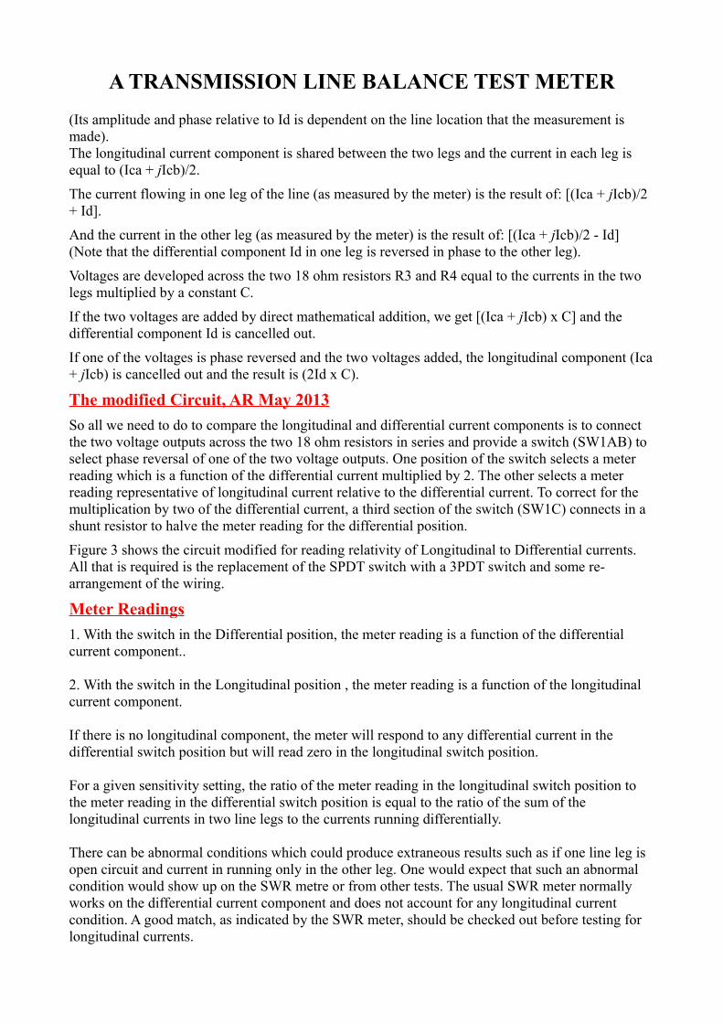
A TRANSMISSION LINE BALANCE TEST METERLloyd also mentions in the original article about using a more sensitive meter movement and another junk box provided a good looking 100uA movement. I had some used die-cast boxes left over from another life and so why not put it into one of those. I may make a drawing of how to wire the rotary switch if anyone is interested.
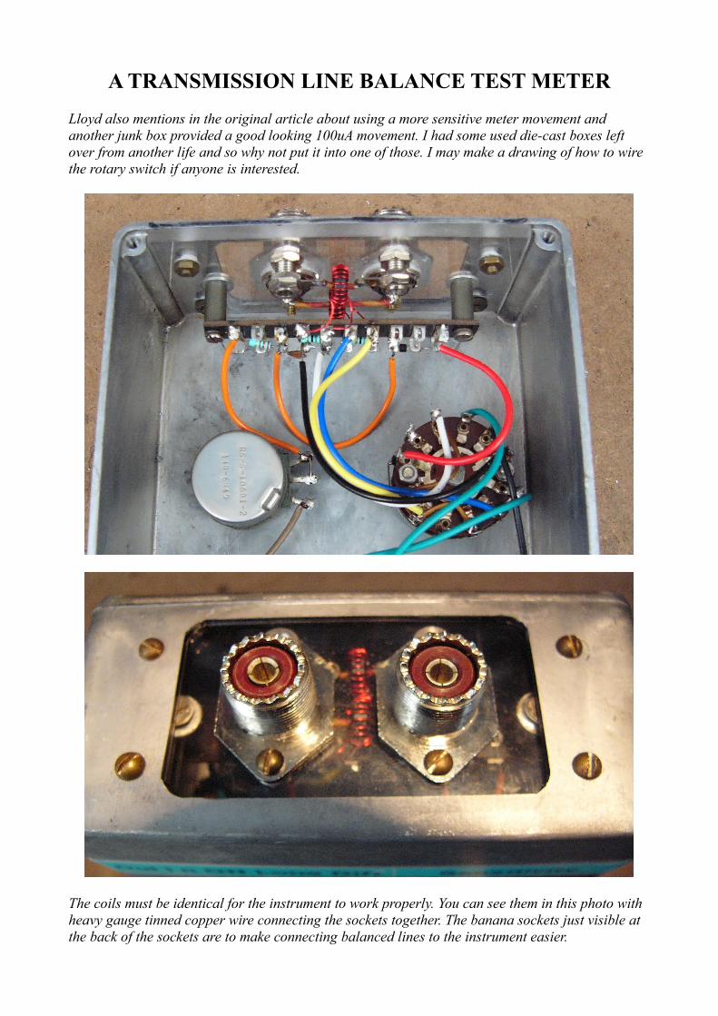
The coils must be identical for the instrument to work properly. You can see them in this photo with heavy gauge tinned copper wire connecting the sockets together. The banana sockets just visible at the back of the sockets are to make connecting balanced lines to the instrument easier.