Embed Size (px)
Citation preview

A “Transmission Time Reservation” method in a
Wireless Lighting Control System
THESIS
Submitted in the partial fulfillment of The requirements for the degree of
MASTER OF SCIENCE
in
Telecommunication
by
Yi Lu Born in Guang Dong, China
Telecommunication group Department of Electrical Engineering Faculty, EEMCS, Delft University of Technology Delft, the Netherlands http://cas.ewi.tudelft.nl

Graduation Committee:
Chairman: Prof. dr. ir. G.J.T. Leus, Faculty EEMCS, TU Delft Committee Member: Prof. dr. ir. G.J.T.Leus, Faculty EEMCS, TU Delft Dr.G.J.M.Janssen, Faculty EEMCS, TU Delft Dr.C.Guo, Faculty EEMCS, TU Delft

Abstract
The lighting industry has been comprehensively developed and deployed during recent decades, especially with the rise of LED technology. As a related technique field, lighting control system has also draw more and more attention; therefore intelligent lighting control systems are needed. Nowadays, several famous lighting companies are working on a next generation of lighting control system, which apply not only a distributed network structure but also wireless communication. Rather than controlling by a single node, a distributed system will finish controlling operation in different control units. This guarantees the distributed system to be more robust and efficient. Wireless technology is also essential for a system because it is infeasible to connect distributed devices with cables. Of all the wireless communication standards, the zigbee protocol is regarded as the best solution for a lighting control system. This is because the zigbee protocol has features of low-rate and low-cost, which perfectly fit the features of a sensor network. However, this application also leads to a problem which cannot be ignored, the coexistence problem with other wireless protocols. Because both of the zigbee and other wireless protocols operate in the ISM 2.4 GHz frequency band, the coexistence problem happens. With different modulation and frequency spreading methods, different protocols will not detect each other correctly, for example if there are two different protocol packets being transmitted, a packet collision will happen. This problem is much more serious for the zigbee service, because the interference from wifi devices will be unacceptable for a zigbee transmission. How to solve this coexistence problem between zigbee and wifi devices in an indoor lighting environment is the main research question of this thesis. In this thesis, several solutions for the coexistence problem between zigbee and wifi are proposed and analyzed. With their different advantages and drawbacks, each of these methods has its own application scene. After comparing, the “Transmission Time Reservation” method has been proved to be a feasible solution as to the assumed problem, which has also been tested by simulations. Within this method, a gateway node between the zigbee and wifi network is designed cooperatively. Whenever there is a zigbee request, this node is programmed to do the reservation operation with the wifi AP node. The results of NS3 simulations and comparative tests have also shown that this method is effective to solve the coexistence problem in an indoor environment. Keywords: Lighting control centralized & distributed zigbee & wifi coexistence

Acknowledgement
This is the master thesis of a graduation project, which was carried out from November 2012 to February 2014 for the Delft University of Technology. Together with the final presentation, this report presents the conclusions for the graduation project of the master program Telecommunication at the faculty Electrical Engineering, Mathematics and Computer Sciences in Delft, The Netherlands. The project is supervised by Ir. Cheng Guo, Prof. dr. ir. G.J.T. Leus and Dr.G.J.M.Janssen. First and foremost, I would like to express my appreciation to my supervisor, Ir. Cheng Guo, who introduced me to the topics of coexistence issues of wifi and zigbee protocols. Besides offering this thesis topic, Ir. Guo also gives me a chance to do cooperative project of lighting control system with staff of other companies. This not only improves my understanding of the basic design of the system, but also gives me a chance to communicate and cooperate with others. This is essential for me to have more practical working experience but also get much more advice from others. When I fond and worked on designing solutions for the coexistence problem, Ir. Guo offered me comprehensive and detailed suggestions. Especially at the very beginning the beginning, I started the design in a wrong direction and. Ir. Guo corrected me in time and showed me the proper methodology which the solutions should have. Secondly, I also want to express my best thanks to the other professor members of my thesis committee, Prof. dr. ir. G.J.T. Leus, Dr.G.J.M.Janssen. They reviewed my thesis project and report with full responsibility and gave me many valuable modification suggestions. Furthermore, I would like to thank my family and friends for their support and suggestions when I hardly can move on. Hope you enjoy reading. Yi Lu Delft, The Netherland 00-00-2014

Contents:
List of Figures:…………………………………………………………………………………………………………………7
List of Tables: ..................................................................................................................... 8
Chapter 1 Introduction ...................................................................................................... 9
1.1. Motivation .................................................................................................................. 9
1.2. Problem description ................................................................................................. 10
1.3. Outline and contribution .......................................................................................... 10
Chapter 2 Technical Background ...................................................................................... 12
2.1. Wireless Lighting Control System ............................................................................. 12
2.1.1. Centralized & Distributed control system ........................................................ 13
2.2. Coexistence interference problem ........................................................................... 14
2.2.1. Overview of IEEE 802.15.4 and zigbee protocols ............................................. 15
2.2.2. Overview of wifi/IEEE 802.11 protocols ........................................................... 17
2.2.3. Compare of zigbee and wifi protocols and related problems .......................... 19
2.2.4. Current methods for the interference problem ............................................... 20
Chapter 3 Coexistence problem and different solutions ................................................... 21
3.1. System model ........................................................................................................... 21
3.2. Double transmission method ................................................................................... 22
3.2.1. Related background introduction ..................................................................... 22
3.2.2. Idea introduction .............................................................................................. 24
3.2.3. Conclusion ........................................................................................................ 25
3.3. Application layer cut-off method ............................................................................. 26
3.3.1. Application layer cut-off mechanism ................................................................ 26
3.3.2. NS3 model and result analyze .......................................................................... 27
3.3.3. Potential interference scenes and conclusion .................................................. 29
3.4. Transmission Time Reservation method .................................................................. 31
3.4.1. Theory of the “Transmission Time Reservation” method ................................ 31
3.5. Compare of different methods ................................................................................ 33
Chapter 4 “Transmission Time Reservation” method ....................................................... 35
4.1. Simulation settings ................................................................................................... 35

4.2. Simulation results and conclusion............................................................................ 36
4.3. Comparative simulations ......................................................................................... 38
4.3.1. Comparative simulations under 802.11 a ........................................................ 38
4.3.2. Comparative simulations under 802.11b ......................................................... 41
4.4. Conclusion ................................................................................................................ 44
Chapter 5 Conclusion and future work ............................................................................. 45
5.1. Conclusions .............................................................................................................. 45
5.2. Suggestions for future work ..................................................................................... 46
Bibliography .................................................................................................................... 47

List of Figures:
Figure 1 example of wireless lighting control system[32] ....................................................... 12 Figure 2 structure example of distributed lighting control system ......................................... 14 Figure 3 zigbee/IEEE 802.15.4 protocol stacks[40] ................................................................. 15 Figure 4 IEEE802.15.4 Frequency Bands ................................................................................. 16 Figure 5 format of IEEE 802.15.4 packet ................................................................................. 16 Figure 6 IEEE802.11 Frequency Bands [52] ............................................................................. 18 Figure 7 IEEE 802.11 MAC Frame Format................................................................................ 18 Figure 8 IEEE 802.11 medium access methods ....................................................................... 19 Figure 9 topology of the system model ................................................................................... 22 Figure 10 transmission scenes of wifi and zigbee packets ...................................................... 23 Figure 11 Potential collision scene under double packet transmission .................................. 24 Figure 12 double header frame structure ............................................................................... 24 Figure 13 transmission scene under triple headers ................................................................ 25 Figure 14 the topology with the Gateway node ...................................................................... 26 Figure 15 process of this application mechanism ................................................................... 27 Figure 16 topology of the simulation model ........................................................................... 28 Figure 17 throughputs of every node during the simulation .................................................. 29 Figure 18 potential collision scene 1 ....................................................................................... 30 Figure 19 potential collision scene 2 ....................................................................................... 31 Figure 20 process of the reservation method ......................................................................... 32 Figure 21 topology of the simulation model ........................................................................... 35 Figure 22 channel occupancy of 802.11b during [3.1s, 3.12s] & [3.8s, 3.82s] ........................ 37 Figure 23 channel occupancy of 802.11a during [3.1s, 3.11s] & [3.5s, 3.51s] ........................ 37 Figure 24 throughput and channel occupancy of the whole system (OFDM 6 Mbps) ............ 38 Figure 25 throughputs of the system under different wifi bandwidth.................................... 39 Figure 26 data rate change every 1s and the channel occupancy .......................................... 40 Figure 27 data rate change every 1/8s and the channel occupancy ....................................... 40 Figure 28 data rate change every packet and the channel occupancy ................................... 41 Figure 29 throughout and channel occupancy (DsssRate 11Mbps & zigbee packet size
2^4Byte) .......................................................................................................................... 42 Figure 30 the unexpected collision scene ............................................................................... 42 Figure 31 the collision probability with increasing packet size ............................................... 43

List of Tables:
TABLE 1 comparison of wifi and zigbee protocols ................................................................... 19 TABLE 2 compare of three methods ........................................................................................ 33
Introduction 1
The focal studies of this thesis are the important issues of applying Wireless Lighting Control System. This chapter gives an overview of the whole project. A study motivation will be given firstly in order to offer more information about the context. Secondly, the most obvious problems of Wireless Lighting Control System will be introduced. Furthermore, an outline will be described together with the main contribution of the thesis in the third section. 1.1. Motivation Among the history of human beings, lighting has been considered as one of the most important inventions by considering it can extend the day time. With the development of related technology, the lighting industry has improved greatly during recent decades. [1]- [3] More attention is paid to improve the efficiency and the life-time of lamps. With the invention of LED light, lighting industry has entered a new era. The LED light has benefits in terms of efficiency, color, lifetime and size on the other hand it can also be used of different occasions with different functions. [4]- [7] With higher functional lighting applications, people are not satisfied by controlling switchers and the lighting control system has been brought to public. The lighting control system should be an intelligent system controlled by computer devices, and the system could arrange all lighting settings among the whole system as to user’s requirements. [8] [10] - [12] For example, people used to switch on light while entering a room. A lighting control system can detect a person coming and turns on the lights automatically. While automatic control being achieved, people request more functions, such as auto-dimming, changing color and emergency alarm. All these convenient functions depend on calculations and arrangements of processors, which requires not only a mature software system but also devices which need support from both a mature software system and robust hardware devices. [9] [13] In order to achieve intelligent lighting control, sensor networks are widely applied to gather scene information. It is not hard to image that, if the control system is applied among a huge environment, the amount of gathered data would be large. While the lighting control system becomes more and more complex, the burden for a central controller to process so much data is increasing rapidly. Distributed control system has drawn more attention and becomes the major choice for lighting industries. With distributed storage and processors among the system, information is transferred more efficiently and robust. There are much more benefits of a distributed system compared to a centralized one, which will be introduced in detail in Chapter 2. [14] - [16] Moreover, while applying a distributed controlling system, the communication method between different system units is also changed from wired to wireless. Compared to wired transmission, wireless communication can greatly save not only power but more important wiring cost. [17] - [20] The convenience of wireless communication perfectly fit the requirements

of a lighting system, such as low-cost and latency. However, the problems of coexistence with other wireless devices, robustness issues and security threads also occur and need to be solved. [21] – [23] For example, there are both Zigbee and Wi-Fi lighting devices existing and they may be used in indoor as well as in outdoor environments. The coordination between them and other wireless devices will be the coexistence issue.
1.2. Problem description Since lighting devices are becoming more common in the daily life, people are chasing for another way to control it rather than do it manually. [8] [10] The intelligent lighting system is required to adapt to people’s different needs. In other words, people want their luminaires to have a “brain” to think and to respond to orders. With developments of computer science and embedded systems, it is possible to fulfill the function of this “brain” by installing an MCU in lights. [9] The control system would be the essential part of this whole system because it controls lights to act as to its decision. Moreover, with an increasing scope of the lighting environment, distributed control systems are regarded as the best option, with its features of high efficiency, robustness and low-cost. [17]- [19] It is easy to image that connecting all devices with cables to share distributed information is infeasible. Wireless communication methods, as the major method since the 21st century, are used in this system. There is an essential coexistence problem happening to the wireless lighting control system. [20] - [23] Since the controlling packets of the system are very short and the throughput of the network should be low. With the great benefit of low-power and low-cost, the Zigbee protocol is regarded as the most suitable solution for lighting control signal transmission [24]- [27]. However, since Wi-Fi is the most on-going Internet protocol, the coexistence problem between these two different transmissions should be solved. [22] This is because both of these two protocols use the 2.4G ISM frequency band and even overlapping channels. It is possible that the channel is fully occupied by the wifi transmission (for example, stream video downloading) [28][30]. If there is no protection is run in the system, packets collisions will happen when there is a zigbee transmission requirement occurring. Moreover, compared to general wifi signals, zigbee signal used for lighting control is in a much lower power level. When transmissions collide, most of the zigbee packet will get lost, which means the lamps will be out of control. 1.3. Outline and contribution This part briefly describes the approach followed in this project. Before describing the content of this thesis in detail, the main contributions have been summarized. The main contributions of this thesis are analyzing the coexistence problem of the zigbee and wifi protocols. This problem has been introduced briefly in the previous part (Chapter 1.2) and will be described in detailed in Chapter 2. In order to achieve a better performance, an analysis study has been down which followed by a comparative study of various methods. After analyzing the different advantages and disadvantages among these methods, explanations of the applicability of each method have been stated (Chapter 3). The “Transmission Time Reservation”

has been chosen as the final method (Chapter 4). By applying this method, a gateway node between wifi and zigbee network has been designed to coordinate the work of both sides. Generally it will act as a common node among both networks. While zigbee network is controlling transmission requirements, the gateway will stop the on-going wifi transmission and reserve transmission time for zigbee. This method is designed to solve most of the interference problems between indoor zigbee lighting system and wifi Internet. Chapter 2: Technical background In this chapter, main features of a mature wireless lighting control system are introduced firstly. This presents a standard requirement of a mature lighting control system. The first part has compared centralized and distributed lighting control system briefly, in order to give background information of the coexistence problem of the system. In the second section, different wireless protocols have been introduced and compared. Advantages and disadvantages of different protocols have been explained and suitable applications have also been analyzed. In order to solve the coexistence problem, features of wifi and zigbee protocols have been further studied. The results of a literature study about the coexistence problem and solutions have also been presented in this chapter. Chapter 3: Coexistence problem and different solutions This chapter explains the main contribution of the project. Firstly, more details of the coexistence problem and potential issues have been stated. A problem scene assumption has been built to explain the problem. Several methods which can be used to solve the problem have also been introduced in this chapter. Furthermore, these methods have been analyzed from different aspects which include drawbacks and applications. Chapter 4: “Transmission Time Reservation” method The “Transmission Time Reservation” has been selected as the final method after comparing with others. In this chapter has been analyzed in depth. AN NS3 simulation has been built followed by performing tests. Moreover, several comparative tests have also been run to prove the scalability of this method. Chapter 5: Conclusion and Future work The last chapter summarizes the main contribution of this thesis and recommendations are formulated for further development on this topic.

Technical Background 2 A Wireless Lighting Control System is an epoch-making technology which has benefits to integrate traditional lighting control together with wireless communication. This new management system is a better way to control lamps from energy consumption aspect, which is also regarded as a way of intelligent lighting control. [10] With the fast growing of LED technology, energy-saving and efficient lighting system is applied into many commercial and public environments. [4] [6] On the other hand, the lighting control system also adopts wireless communication, computers and sensors. This could not only guarantees normal lighting functions but also achieves energy-saving and intelligent management. With further research on wireless control system, the most evident problem, the coexistence problem occurs. This thesis will explain the coexistence problem between wifi and zigbee protocol, which is also the main research question of the whole project. In this chapter, features of a mature wireless lighting control system are introduced firstly. Centralized and distributed lighting control systems are also compared briefly. This leads to the reason of the coexistence problem. Secondly, the coexistence problem is analyzed in detail. With different protocols, this problem shows various features. Our work mostly focuses on the collision between wifi and zigbee protocols, which is regarded as the most common problem. [32] Current research and methods about this issue are analyzed. With different ideas, different solutions have their own advantages and drawbacks. 2.1. Wireless Lighting Control System As mentioned in the previous part, a wireless lighting control system has been regarded as the best option for modern lighting system with a huge number of lights/lamps. [19] [24] There are mainly three key technique issues happen to this control system, namely sensor network, functional processors and wireless communication.
Figure 1. Example of wireless lighting control system[32]

Figure 1 has shown a simple example of a wireless lighting control system. The operation of the control system can be stated as the following sentences. Firstly, the sensor network will detect and gather useful information for automatic control. These data is transferred to the local controller containing a processor. After processing the incoming information, the controller will make a decision for all lamps and schedule these changes. All information transfer is achieved though wireless communication. 2.1.1. A centralized or a distributed control system With increasing scale of the lighting system, the sensor network becomes more complex and there are more devices needed. For example, in a lighting system of a commercial building, there are different sections such as hall and offices. There are two different ways to arrange devices of the system, a centralized or a distributed structure. [14]- [16] A central processor is a necessary component for applying a centralized control system. Sensors transfer all information to this device to make decision. There are certain action rules stored on the central node. After receiving useful scene information, the controller will check its database to trigger rules. During the processing procedure, the controller could generate an action order and send it to related lamps. This controller finishes all arrangements of the system to achieve automatic control. The whole system will work more efficient by applying the centralized structure. All information is collected at the control node and operated on together. This greatly saves the overlapping transmission and lows architecture cost. Devices are only connected to the central node. It is also convenient to operate the control system since the structure is clear, which means the central node will be the only focal point. On the other hand, couples of drawbacks of the centralized structure have also been found. It is difficult to handle all received information among a single node with increasing scope of detecting area. The controller includes more than one interface. The controlling packets would suffer a large great collision possibility since all information has been sent to a same node. It will become worse, if the controller collapses suddenly, the whole system will fail until the central node fixed. The vulnerability of this centralized structure determines it can only be applied among small lighting environment. On the other hand, of a distributed control system, there are different local units divided of the whole environment. [15] Each unit has its own local processor and it is connected to a central management device. The system structure has been shown in Figure 2.

Figure 2. Structure example of distributed lighting control system
In this system, sensor information is shared with a local control unit, but not all of it is submitted to a central node. This can greatly improve the robustness of the system since data transfer is distributed to different units [14]. Each control unit has its own processor to handle sensor information and the work flow of each local controller is same as the central node which has been introduced in the previous part. When there is any collision happens, it will only affect its own unit and other units can run without problems. Moreover, there are different functions installed at different local units. For example, the controller of the main hall will care more about people’s appearance while the one of office focuses more on people presence and distribution. This makes the lighting system more methodical. Compared to the centralized structure, the architectural cost of a distributed system is higher. If the usage environment is large, it would require a large number of local processors. Above all, it is infeasible to connect all the devices in a distributed system via cables. Since the system information in distributed structure is shared with different units and processors, rather that gathering together. [33] Communication between different devices is required and there are much more connections compared to a centralized system. In order to achieve this goal, wireless communication becomes the feasible solution. With the good scalability of wireless network, the distributed system can operate fluently. Moreover, with the great benefits of low-cost and low-energy consumption, the zigbee wireless protocol is recognized as the more appropriate protocol for lighting control among the industry. [25] [27] More technical detail about zigbee protocol will be introduced in a later section. With the increasing popularity of the zigbee protocol within the lighting industry, the coexistence problem with other on-going wireless protocols becomes an essential issue. 2.2. Coexistence interference problem A mature wireless lighting control system should be intelligent and stable at the same time. When applying wireless communication to achieve distributed control, a coexistence problem between zigbee and wifi protocols has come out which attract the attention of the author. [34]- [36] The later part of this thesis will introduce this phenomenon and show related solutions. In

this section, the problem is explained by comparing of these two common protocols. The most fundamental reason of this problem is that both of these two protocols apply the same ISM frequency band to communicate. Lastly, Frequency hopping has been introduced, which is regarded as the most effective way to reduce interference. 2.2.1. Overview of IEEE 802.15.4 and zigbee protocols IEEE 802.15.4 is a protocol designed for LR-WPAN defining the specification of PHY and MAC layers, while zigbee is a protocol providing NET and APP layer specification and based right on top of the IEEE 802.15.4 specified layers. [37]- [39] The protocol architecture is presented in Figure 3.
Figure 3. Zigbee/IEEE 802.15.4 protocol stacks[40]
i) IEEE 802.15.4 protocol The IEEE 802.15.4 protocol specifies two fundamental layers for WPANs, MAC and PHY layers. It is designed to achieve low-cost, low-speed transmission. [41] - [45] The most typical application of this protocol is the sensor network, which has features of simple infrastructure, limited resources and low energy consumption. IEEE 802.15.4 PHY layer: [41] The PHY layer protocol works on physical data transmission. It also provides the interfaces to the upper management entity. Contributions of the PHY layer include media energy detection, link quality indication (LQI), channel selection and transmission of the generated PHY packets. In global, it works on the unlicensed ISM frequency bands:

● 868.0-868.6 MHz: 1 channel, used in Europe. ● 902-928 MHz: 10 channels, used in North America. ● 2400-2483.5 MHz: 16 channels, used worldwide.
Figure 4. IEEE802.15.4 Frequency Bands
Figure 4 has shown the IEEE 802.15.4 band location. The protocol applies direct sequence spread spectrum (DSSS) on all bands. The transmission rates of 868 and 915 MHz bands are 20 and 40 Kbit/s, while 250 Kbit/s in the 2.4 GHz. [45] Normally, the 2.4 GHz band is used in situations with a higher data rate and more channels. Figure 5 shows the format of a 15.4 packet including the Synchronization Header (SHR) and the PHY Header (PHR). Byte: 4 1 1 0-125 2 SHR
Figure 5. Format of IEEE 802.15.4 packet As shown in figure 5, the SHR includes a 4-byte preamble sequence and a 1-byte Start of Frame Delimiter (SFD). The aim of the 4-byte preamble is synchronization, establishment acquisition of symbol and chip timing. Moreover, the payload can extend from 2 to 125 bytes. IEEE 802.15.4 MAC layer: The MAC sublayer is responsible for data communication with other terminals and corresponding management services. Its data service enables the basic function of data transfer among neighboring devices, mainly the transmission and reception of the MAC protocol data units (MPDU) across the PHY data service. On the other hand, its management services include management interface to the physical channel, network beaconing, control frame validation, guaranteed time slot (GTS) mechanism and handles node associations and disassociations.
Preamble SFD PHR Payload CRC

Furthermore, the IEEE 802.15.4 standard enables a super frame beacon mechanism in namely beacon mode. In this mode, dedicated bandwidths used for different applications are arranged. This method is applied to reduce the latency, which is a key requirement for many communication applications. In this beacon mode, there is a coordinator who will periodically broadcast beacons. These beacon signals are used to synchronize the connected terminals. With this mechanism, packet interference between neighboring devices is prevented. On the contrary, there is also a non-beacon mode which applies with a simple and traditional channel access method. The other important functions of the MAC sublayer, such as real-time suitability by reservation of GTS in the beacon mode, will not be introduced detailed in this thesis, since they are not deeply involving with later works. ii) Zigbee protocol The zigbee protocol provides the network and application layer protocols for WPAN. The most important characteristic of the zigbee standard is the full meshing capability. A zigbee network could contain more than 50,000 devices. Due to this feature, the zigbee network is often used in the sensing and detecting wireless networks. A Cluster-Tree algorithm and Ad hoc On Demand Distance Vector (AODV) algorithms are applied among zigbee networks. These technologies are used to reduce the power consumption and helped to improve the reliability of devices/applications. The zigbee protocol shows great advantages, such as low-cost and low-speed, to the controlling industry, because the controlling signal always performs in a short and simple format. [47] 2.2.2. Overview of wifi/IEEE 802.11 protocols IEEE 802.11 series standard is the most popular on-going protocol used for WLANs. It is easy to install. For this protocol, a network adapter is used to connect to an Access Point to get access to the Internet. It defines the PHY and MAC layer specification and determines the communication protocols handling data which is transferred at each layer. [48]- [51] IEEE 802.11 PHY layer: IEEE 802.11 PHY layer protocol defines the data rate, frequency band and some other parameters for the actual radio transmission. There are mainly three physical technologies: Direct Sequence Spread Spectrum (DSSS), Frequency Hopping Spread Spectrum (FHSS) and Infrared (IR). As the most common-used technology, the DSSS maps each data bit into a string of bits regarding 1/0. The DSSS method can increases data rate and is more robust against more interference compared to FHSS. IEEE 802.11b is an extended version of 802.11a providing data rates of 1, 2, 5.5 and 11 Mbps. The 11b standard applies Complementary Code Keying (CCK) as the modulation method. The 802.11B protocol is widely used in people’s daily networks due to its own characteristics. There are IEEE 802.11 devices and access points in an 802.11 network. Transmission is run on the ISM band. There are 14 frequency channels of the whole bandwidth, each of them is 22 MHz wide and only 3 non-overlapping channels. Figure 6 below shows the distribution of the frequency bands. [56]

Figure 6. IEEE802.11 Frequency Bands [52]
IEEE 802.11 MAC layer: The IEEE 802.11 protocol provides data frames for transmission. [53] [54] The generation of a certain format of a data block is the main contribution of this MAC layer. There are much information included in the frames, including the source and destination address, control and check bits and user data. The structure of an 802.11 MAC frame is shown in figure 7 Bytes: 2 2 6 6 6 2 6 0-2312 4
Figure 7. IEEE 802.11 MAC Frame Format
There are two access medium mechanisms applied in the 802.11b/g MAC layer: the Distributed Coordination Function (DCF) and the Point Coordination Function (PCF). [58]- [60] DCF defines a contention based access mechanism which is based on the CSMA/CA scheme. [55] [56] Ordinary asynchronous traffic uses the DCF functionality. PCF defines a centralized and polling based access mechanism for accessing the wireless medium and it provides contention free time intervals. The implementation of DCF and PCF mechanisms makes use of service differentiation principles that are based on transmission timing constraints. Three different inter-frame space intervals are used among the 802.11 MAC layer protocols. The short Inter Frame Space is applied for transmissions with a high priority, such as Clear-To-Send (CTS) and Acknowledgement (ACK) frames. PCF Inter Frame Space (PIFS) has a medium length used by the coordinator node. The beacon frame is broadcasted by this node to inform other nodes that a PCF period starts. The beacon frame includes the time the nodes should refrain from transmitting at free will and do so only if polled by the coordinator. The DCF Inter Frame Space (DIFS) is the longest IFS and has the minimum time slot for asynchronous frame contending. Figure 8 has shown the basic medium access method for IEEE 802.11 standard.
Frame
Control
Duration
ID
Address
1
Address
2
Address
3
Sequence
Control
Address
4
Frame
Payload FCS

Figure 8. IEEE 802.11 medium access methods
The CSMA/CA mechanism is designed to reduce the occurrence of packet collisions. It asks every connected terminal to detect the medium just before attempting to send a packet. These collisions happen because devices work on the same frequency channel. There are two methods of medium detection applied among the DCF: virtual and physical carrier sensing. The virtual carrier sensing method applies the Request-To-Sent (RTS) /Clear-To-Sent (CTS) mechanism. [57] In this case, the RTS and CTS frames are used to reserve the channel from other devices. This is reserved for the incoming data transmission. As to the physical carrier sensing method, every device will detect the medium before sending a packet. If the medium is busy, it will go into a back off procedure. 2.2.3. Comparison of zigbee and wifi protocols and related problems The general background information of the zigbee and wifi protocol stacks has been introduced in the previous two sections. Table 1 has summarized most of the features of these two standards.
TABLE 1 Comparison of wifi and zigbee protocols
Standard Wifi Zigbee IEEE spec. 802.11 a/b/g 802.15.4 Frequency band 2.4 GHz; 5 MHz 868/915 MHz; 2.4 GHz Max signal rate 54 Mbps 250 kbps Nominal range 100m 10-100m Nominal TX power 15-20 dBm (-25)-0 dBm Number of RF channels 14 (2.4 GHz) 1/10; 16 Channel bandwidth 22 MHz 0.3/0.6 MHz; 2MHz Modulation type BPSK, QPSK, COFDM, CCK BPSK (+ ASK), O-QPSK Spreading DSSS, CCK, OFDM DSSS Basic cell BSS Star Max number of cell nodes 2007 >65000 Data protection 32-bit CRC 16-bit CRC
As mentioned in Chapter 1,the most fundamental reason for the collision interference problem

between wifi and zigbee protocols is that both these two standards use the same unlicensed frequency band, the ISM 2.4 GHz band. Even though there are many channels among the whole band, it is possible that both of them have selected channels with an overlapping band. In this case, their transmissions will interfere with each other. Moreover, as shown in Table 1, it is obvious that the TX power of a zigbee packet is much lower than for wifi. So the zigbee signal will interfere the wifi transmission only within a close range. On the contrary, the wifi transmission signal will cause serious interference to the zigbee transmission. While the wifi packets increase, the channel would be too busy for zigbee devices to transmit. This conclusion is based on amount of previous studies. All of them have shown that 15.6 performances significantly degrade in the presence of 802.11 interferences. The easiest method to mitigate this interference problem is trying to avoid channels occupied by 802.11. [62] - [63] 2.2.4. Current methods for the interference problem Normally, mainly two methods are used to avoid interference: static channel assignment and dynamic channel assignment. The first method works under the assumption that the 802.11 transmission only occupies a fixed number channels. In this case, the 15.4 channels, which have no overlapping with the fixed 802.11 channels, would be used for 15.4 transmissions. With the increasing popularity of wifi transmission, this static method becomes unrealistic. Moreover, this static assignment may be out of work due to device mobility and incremental wifi deployments. As to the dynamic channel assignment method, nodes among the 15.4 channels are using different channels for transmission to avoid interference from nearby wifi devices. This mechanism may work between different sensor nodes or different time points of the same node. [31] [64] [65] There are two key issues of these two mechanisms. [64]- [66] Firstly, the technology of detecting the presence of the 802.11 traffic would be difficult. Because the 802.15.4 protocol is mostly applied among sensor networks, this type of network devices is simple with low calculation capacity. To detect the other protocols’ transmission requires more functional detecting technology, which also requires higher performance devices. The other issue is to coordinate channel selection among 15.4 senders and receivers. In order to achieve automatic channel selection, more cognitive radio and synchronous technologies need to be applied. Normally, people switch the transmission channel manually by switching or pressing a bottom. This method will not only bring doubt to clients without related knowledge, but also is not realistic for use in huge sensor networks. Except the coordination complexity, these channel selection methods would cause large portions of unused frequency band. This is because the wifi signal has much higher power and zigbee transmissions will all try to avoid even a small 802.11 signal. This inefficiency is especially harmful to the application of 802.15.4 protocols in large and dense sensor networks, since the throughput needs to be guaranteed.

Coexistence problem and different solutions 3
As introduced before, more and more wireless technologies works on the unlicensed frequency bands, which can be exploited by multiple devices. Because of the mutual interference, the coexistence of different standards working in proximity of each other would be a serious problem. Many researches have proved that the interference phenomenon happens more seriously among the zigbee networks, whose performance is heavily influenced by the presence of wifi transmissions. Implementation of collision avoidance schemes is feasible method to avoid interference among terminals sharing the same channel with a same standard. However, the application of incompatible modulation methods and channel access schemes make it virtually impossible to guarantee the transmission between devices with different protocols. It is easy to imagine that the most direct way to solve this problem is licensing frequency bands for authorized clients. In this way, some users with higher priority can enjoy communication without interference. However, this will not only lead to a low utilization of the licensed bands, but also cause more traffic jams among the unlicensed bands. Solutions with a better performance should be developed. As mentioned before, it is believed that the way to avoid this interference is static /dynamic channel assignment, which is too complex and inefficient for dense zigbee networks. In this section, some optional solutions for this problem are analyzed and developed. Firstly, a demo assumption has been built to make the problem scene clear. Secondly, three optional methods to mitigate the interference are described, with their applicable scenarios and drawbacks. Lastly, these different methods are compared with their different features. The “Transmission Time Reservation” method is regarded as the most feasible method and its performance has been tested which will be explained in Chapter 4. 3.1. A System model This system model is built based on a practical experience that occurred at the author’s supervisor’s home. There are two existing wireless systems, a WLAN for Internet access and a small WPAN for lighting control. These two wireless systems share the same 2.4 GHz frequency band. The interference problem happens in the situation that, if someone downloads streaming video through the wifi access point, the lighting control system will be out of operation and lamps could not be remotely controlled. The topology of this model is shown in figure 9.

Stream data transmission
Control signal transmission
Figure 9. Topology of the system model
In this model, there are two wifi nodes in the wifi network. One is the Access Point (AP) while the other one could be a normal terminal, such as a laptop or a tablet. This is common in people’s daily life. The number of wifi devices will affect the channel occupation situation. In this model, the author tries to increase the rate of the streaming data transmission to simulate a practical situation, rather than increase the devices number. The zigbee network also contains two nodes, one is a zigbee remote controller and the other is a lamp with a zigbee receiver. Controlling signals would be sent directly if necessary. These two networks operate in a same indoor environment, which may cause the interference problems. In the model, the author has made the assumption that the wifi receiver is downloading streaming data from the AP node, such as watching YouTube video. The frequency channel is in high occupancy of the wifi signal. In this situation, the zigbee packets will face a high collision risk. Actually, the remote controlling will mostly be out of order, which means the control signal is interfered and cannot be received. 3.2. Double transmission method In this section, a Double transmission method to reduce the interference effect is introduced. As the name suggests, the author continuously transmits the zigbee control packet twice without interval every time when the zigbee network has a sending requirement. In this way, the first packet is sacrificed in order to guarantee successful transmission of the second one. More details will be described below. 3.2.1. Related background introduction Before showing the methodology of this method, it is necessary to introduce some related features of both 802.11 and 802.15.4 networks. There are three Clear Channel Assessment (CCA) methods specified among the 802.11 standard, which are energy detection, packet detection and both. In the energy detection mode, devices will detect the energy level across the channel. If it is higher than the threshold, the channel will be regarded as busy. This mode seems inefficient and packet detection is more commonly applied among the current networks. 802.11 devices with packet detection mode cannot decode the 15.4 packet transmission because of the different
Wifi AP Wifi node
Zigbee Zigbee lamp

modulation and header decoding used. So it will ignore the on-going 15.4 packet and declare the channel to be clear. This is also a reason that the 802.15.4 transmission could bring little interference to the 802.11 network. On the other hand, in the 15.4 network, simple “energy above threshold” CCA method is applied, which means the CCA would report a busy medium upon detecting any energy above the threshold. This will cause that 15.4 transmissions are seriously influenced by on-going 802.11 communications because the TX power of 802.11 is much larger than the threshold. Actually, most of the previous research on the interference problem focuses more on the macro performance of the wifi and zigbee networks, such as the packet reception rate. In this section, the collision positions are analyzed. As introduced before, the maximum transmission rate of the 802.15.4 network is 250 kbps, and 54 Mbps for the 802.11 network. Normally, the wifi bandwidth access in people’s daily environment is about 10 Mbps. The normal sizes of UDP (used among stream data transmission) and zigbee packets are about 500 and 30 Bytes. After calculation, it could be found that the general transmission times for zigbee and wifi packets are about 1ms and 0.5ms. This data is an approximate value in a practical situation, while both of the packet sizes could be adjusted. In this estimate, the transmission time of zigbee packets are almost twice that of a wifi packet, which the key feature we could make use of is. It can be concluded form the discussion above that normally wifi devices will not detect zigbee transmissions, but the zigbee transmission will be interfered. This means the zigbee transmissions have to back off until the end of the on-going wifi transmission. In the situation of streaming data sending, there are continuous wifi UDP packets to be sent and it is very well possible that, after a back-off time, both wifi and zigbee start transmitting within a short time difference. So the transmission time distribution is shown in Figure 10. BO 802.11 BO collision coll.
802.15.4
BO: back-off time
Figure 10. Transmission scenes of wifi and zigbee packets This causes a large number of bit errors at the beginning of a 15.4 packet. This also gives an explanation of the real-life problem. Practically, when streaming data is being transmitted on the channel, the zigbee system is mostly out of order. This explains that most of the zigbee packet are lost, but not interrupted. As introduced in Chapter 2, the front part of a 15.4 frame contains both the SHR and PHR headers. There are Preamble and SFD flags among the SHR header. If the radio cannot properly decode the SHR header, it cannot match the Preamble and the packet will be misinterpreted as channel noise. Furthermore, if the length flag of the PHR is corrupted, the

received packet would be incomplete or contain waste additions because the length estimate is wrong. All these cases will lead to a CRC failure and the packet is discarded. 3.2.2. Idea introduction Since data collision happens mostly at the front part of a zigbee packet, the most direct method is transmitting two zigbee packets back-to-back. The use of the first packet is to pass the time duration with a higher collision probability. Then the second packet has a much higher possibility to be received correctly. The first packet can be a copy of the valid second one, or just take some dummy information. However, transmitting two packets back-to-back has serious potential problems. Firstly, both sides of sender and receiver need to be designed particularly. They must be off-line designed to be able to receive two packets back-to-back, which mean it can decode the whole packet twice continuously. What is worse is that the double packet transmission will greatly extend the time of zigbee transmissions. This will not only lead to a great amount of resource wasting, but the later part of the transmission suffers from collision probability. This is because the double transmission may last until a second wifi transmission starts. The potential collision situation is shown in Figure 11. BO
Wifi BO EC UC
Zigbee
BO: back-off time
EC: expected collision
UC: unexpected collision Figure 11. Potential collision scene under double packet transmission
Actually, it is unnecessary to double transmit the whole packet to avoid front part collision of the first packet. Since the bit errors happen mostly in the front part, obviously double header transmission will be more efficient and effective than double packet transmission. The frame example of this method is shown in Figure 12. 4 1 1 10 4 1 1 10 0-115 2 First header Second header
Figure 12. Double header frame structure
First packet Second packet
Preamble SFD PHR MAC Preamble SFD PHR MAC Payload CRC

Rather than double packet transmission, double header sending is more feasible because of the simple decoding approach that the 15.4 standard uses. 15.4 devices transmit the whole packet with the same modulation scheme and bit rate. If a 15.4 receiver successfully detects the SHR and PHR headers, it continues to decode the incoming data until the length mentioned in the PHR header. In application of this length byte, it is safe to double or even triple the header in a single 15.4 packet. The receiver will regard the extra header as part of the data unit. The transmission situation has been shown in Figure 13.There are two extra headers added in front of the packet in order to avoid collisions. In this situation, if the channel is free and there is no wifi signal, the receiver will detect the first SFD byte after the first preamble sequence. This will inform the receiver that this is the start of this packet and it will regard the second and third headers as part of the payload. On the other hand, if the first and second preamble bytes are corrupted due to 802.11 interference, the receiver will not detect the first and second headers correctly. It will further regard the received signal as channel noisy until it detects the third SFD after checking the four preamble bytes correctly.
BO Wifi BO EC Zigbee BO: back-off;
1/2/3: first/second/third headers
Figure 13. Transmission scene under triple headers 3.2.3. Conclusion Even though it can mitigate the 802.11 interference with little cost, this double header method has its own drawbacks. Firstly, since there are multiple headers applied, the information of each header must be properly adjusted. As shown in figure 13, the third header has the real information about this packet. The receiver’s software stack should be able to adjust the received packet and remove all extra headers from the payload before delivering the packet to the user application. Secondly, the CRC byte at the end of this packet should be disabled. Since we have no idea which header would be correctly detected, the total length and payload part would be changeable. This would not allow CRC checking and the CRC byte should be disabled.
1. 3. 2.

All these disadvantages have led to new technical requirements. The software stack installed in this 801.15.4 network should do complex operations to achieve all these functions. As mentioned before, just like the channel selection methods, large processors are infeasible to be installed in large and dense sensor networks. This also conflicts with the low-cost and low-energy features of WPAN. In conclusion, this method can effectively mitigate the 802.11 signal interference theoretically and it can be applied in related experiments and researches. However, it is infeasible to apply this mechanism among dense sensor networks. The wifi side needs to be considered more in this case. 3.3. Application layer cut-off method In the last section, a technique to improve the zigbee device side has been proposed. Due to the high installing cost among dense sensor networks, the double transmission method seems infeasible. Changes of the wifi side are considered. In this section, changing of the wifi application layer has been implemented to avoid interference. 3.3.1. Application layer cut-off mechanism The most direct idea to solve this interference problem on the wifi side is by stopping the on-going streaming data transmission, while there is a zigbee packet need to be sent. Just like the implementation of traffic lights, when pedestrians want to cross the road, they will inform the system (by pressing a button) to stop the traffic. The traffic light is the central part of the system. If we want to stop the streaming data transmission, a traffic light function should be implemented. The device should be designed to be able to communicate with both networks, just like a functional gateway node. The topology of these devices is shown in Figure 14. Stream data transmission
Control signal transmission
Figure 14. The topology with the Gateway node
Wifi AP Wifi node
Zigbee controller Zigbee lamp
Gateway node

With this functional gateway, operations based on the “stopping the streaming data transmission temporarily” idea are implemented in the system. Normally, this G node will act as a normal terminal for both sides. Once the zigbee network gets control signal to be sent, it will inform the G node to stop any on-going 802.11 transmissions for certain duration. After transferring this message to the wifi AP node, application software should be run among the AP device to cut off the current transmission. After these operations, the zigbee sender can safely deliver the data among preset transmission time. The whole process of this application mechanism is shown in Figure 15. Send request
Cut-off request
Send response
Figure 15. process of this application mechanism
This method straightforwardly solves the coexistence problem by cutting off the interference source. While all the wifi transmission is stopped, the frequency channel will be free and zigbee packets could be correctly received. In order to test the effectiveness of this method, an NS3 simulation model has been built to test its performance. 3.3.2. NS3 model and result analyze To exam the performance of the application layer mechanism, an NS3 model of the solution is built. There are 5 nodes among this NS3 model and the topology is shown in Figure 16.
Wifi receiver Wifi AP Node G Zigbee sender Zigbee receiver
Stream data
transmission
Control data
transmission
Stream data
transmission

Figure 16. Topology of the simulation model
In this model, node A is a normal wifi device. Node B is the gateway node which communicates with both networks. Both node A and B are connected to the AP node and these three nodes build up a small size WLAN network. On the other hand, because there is no implementation of the 802.15.4 standard stack of the NS3 system, two alternative wifi nodes are assumed to be the two zigbee nodes. These two nodes build up a simple WPAN network. Node C is a zigbee sender and node D is the receiver. The bandwidth of the WLAN network is set to 10 Mbps, while the WPAN one is set to be the typical value of 250 kbps. The AP node keeps on sending UDP packets to node A. This implementation is used to simulate a practical streaming data transmission scene. The two networks operate on the same frequency channel so there is a collision probability. There is also a zigbee control signal with a size of 1000 bits, which will be sent as a request. There are two applications installed at the AP point. The first one is the UDP application between AP and node A. The second application is designed to stop an on-going transmission for certain duration of the AP node. This application will be run once the AP receives a requests from the gateway node B. This is the protection application installed at the AP node. As described before, after stopping the wifi communication, the zigbee sender will send the 1000 bits packet. In this simulation, some duration parameters are assumed. The UDP application starts from 2s to 6s. The zigbee transmission request will be generated at 3s, and send the packet after 0.1s. This interval is saved for the process of stopping. The cut-off duration is set to be 1s, in order to clearly see its performance. This time could be set to any duration of a zigbee transmission. The result is shown in Figure 17.

Figure 17 throughputs of every node during the simulation
Figure 17 has shown the throughput of every node during the whole simulation process. It can be clearly seen that the AP node keeps on sending data to node A from 2s to 6s, except the 1s interval in the middle. The cut-off interval is caused by the zigbee request and application schedule. After that, the 1000 bits zigbee packet is also correctly transmitted, as shown by the figure 17 and the gathered data. 3.3.3. Potential interference scenes and conclusion There are potential interference risks while applying this Application layer Cut-Off method. Firstly, with this designed application, we can stop the on-going wifi transmission to guarantee transmission of the zigbee control signal. However, it cannot be guaranteed that during the zigbee transmission duration, other wifi nodes will not send any data to the AP node. If this situation happens, the wifi packet would still interfere the zigbee signals.

wifi node -> AP
AP -> wifi node
EC UC
Zigbee
EC: expected collision
UC: unexpected collision
Figure 18. Potential collision scene 1
As shown in Figure 18, the green transmission is the on-going wifi transmission when there is a zigbee sending request. The last part of this green transmission is stopped for the zigbee transmission. The green transmission will not cause interference so the expected collision will not occur. However, during the transmission time of the zigbee packets, unexpected collisions will happen if some other wifi devices send data to the AP node. The red transmission above indicates the unexpected wifi packet. This phenomenon happens because the designed application can only stop transmission on the AP device, but not prevent from other wifi devices sending data to the AP. Though the uplink data is much less than downlink, there is still a potential collision possibility. Secondly, this method can stop current transmissions on the application layer, but not prevent generation of a new wifi transmission during the zigbee time. For example, when there is a zigbee control packet to be sent, the on-going wifi transmission is stopped by cooperation of the AP and gateway nodes. Then the zigbee packet is sent safely. Before the end of this zigbee transmission, the AP node can still have new wifi transmission generated. This is because the AP node is only asked to stop the on-going application, but this does not prevent generation of a new transmission. The potential collision situation is shown in figure 19. The red transmission stands for the unexpected wifi packet generated by the AP node towards other wifi devices. This situation cannot be avoided by the designed application because the usage of this application to stop a current transmission. To achieve a totally safe zigbee transmission, more protection should be added to this method.

wifi
EC UC
zigbee
Figure 19. Potential collision scene 2
It can be concluded from the discussion, though the simulation shows positive result, there is still high collision probability while applying this solution. Since it can stop current on-going wifi interference, this method would be effective when wifi transmissions are few and scattered. However, when the wifi data is in great amount, such as streaming data transmission, there will be high possibility that a new wifi packet will occur during the zigbee time. Furthermore, the cut-off wifi packet will be lost and this will also affect the quality of wifi application. If this discarded wifi packet is only a frame of a stream video, the audience may not realize it. But if it is a part of a data application, errors may occur because of this cut-off action. From these discussions, it can be seen that this method is inadequate to be applied on the lighting control system and more protection should be included for this method. 3.4. Transmission Time Reservation method The basic idea of Transmission Time Reservation method is to reserve transmission time for the zigbee transmission at the gateway node. The zigbee transmission time is reserved by generating a virtual wifi packet by the gateway node. More details will be given in following paragraphs. 3.4.1. Theory of the “Transmission Time Reservation” method Similar to the previous topology, a gateway node, node B, is applied to connect both the wifi and the zigbee network. The G node has both wifi and zigbee protocol stacks, which means it can work as a normal STA node at both sides. Moreover, it has an additional function besides informing both networks. When a zigbee node has a transmission request, the zigbee sender will inform node B to reserve a related time for this zigbee transmission. The basic function of this gateway devise is to reserve transmission time for zigbee data. When the zigbee network has no communication requests, the gateway, node B, works as a normal STA device among both networks. When the zigbee node has a packet to sent, node B will generate certain size of virtual data to be sent to the AP. However, this generated packet will not be sent but only reserve transmission time with the AP. The virtual packet size is proportional to the zigbee packet, which can ensure the reserved time is enough for the zigbee transmission. After the reservation, the zigbee node will be informed to send packets and the emission level of node B will be set to a low level which will be regarded as normal channel noise and not enough to

disturb the zigbee transmission. Since the transmission time is reserved by this virtual packet, data transmission between AP and other nodes will be stopped and the zigbee packet can be transmitted successful. The process of this method is shown in Figure 20. Reservation request
Transmission request
Reservation response
Figure 20. Process of the reservation method
To achieve this reservation goal, the gateway, node B, needs to communicate with the AP node to stop the on-going transmission for certain duration. It can neither generate interference during this time. The bottleneck of this methodology is that no change should be made in the protocol stacks of other devices except the gateway node. This is the most practical and efficient way to solve this interference problem. However, if an AP device is installed practically, the wifi network will apply the PCF (Point Co-ordination Function) access control, which means the AP device will control and schedule the communication between all nodes among the network. Before this reservation method, different methods are tried in node B to reserve time for the zigbee transmission. For example, reducing the data unit size has been tried. However, these methods do not success to reserve because of the uncooperative work with the AP device. Since there is little work we can do with the protocol itself, some “hacker” methods are especially designed to achieve this goal. In the Transmission Time Reservation method, a special tool should be installed in the gateway node to adjust the emission level to a proper value, which could be recognize by the AP node but would not interfere the zigbee transmission. This output power is too low to transmit data, but it can be used to do a reservation via closed indoor environment. Moreover, application with special functions should also installed on node B. This app could receive transmission requests from the zigbee spoken node, do the whole reservation process and send back a response. This requires the gateway device to have a strong processing capability and
Wifi receiver Wifi AP Node B Zigbee sender Zigbee receiver
On-going Wifi packet
Zigbee packet
Next wifi packet
Virtual wifi packet
Opmerking [w1]: Figure 20.
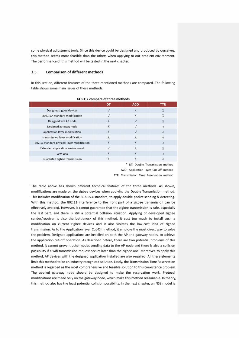
some physical adjustment tools. Since this device could be designed and produced by ourselves, this method seems more feasible than the others when applying to our problem environment. The performance of this method will be tested in the next chapter. 3.5. Comparison of different methods In this section, different features of the three mentioned methods are compared. The following table shows some main issues of these methods.
TABLE 2 compare of three methods DT ACO TTR
Designed zigbee devices √ X X 802.15.4 standard modification √ X X
Designed wifi AP node X √ X Designed gateway node X √ √
application layer modification X √ √ transmission layer modification X X √
802.11 standard physical layer modification X X √ Extended application environment √ X X
Low-cost X X √
Guarantee zigbee transmission X X √
* DT: Double Transmission method
ACO: Application layer Cut-Off method
TTR: Transmission Time Reservation method
The table above has shown different technical features of the three methods. As shown, modifications are made on the zigbee devices when applying the Double Transmission method. This includes modification of the 802.15.4 standard, to apply double packet sending & detecting. With this method, the 802.11 interference to the front part of a zigbee transmission can be effectively avoided. However, it cannot guarantee that the zigbee transmission is safe, especially the last part, and there is still a potential collision situation. Applying of developed zigbee sender/receiver is also the bottleneck of this method. It cost too much to install such a modification on current zigbee devices and it also violates the low-cost idea of zigbee transmission. As to the Application layer Cut-Off method, it employs the most direct way to solve the problem. Designed applications are installed on both the AP and gateway nodes, to achieve the application cut-off operation. As described before, there are two potential problems of this method. It cannot prevent other nodes sending data to the AP node and there is also a collision possibility if a wifi transmission request occurs later than the zigbee one. Moreover, to apply this method, AP devices with the designed application installed are also required. All these elements limit this method to be an industry recognized solution. Lastly, the Transmission Time Reservation method is regarded as the most comprehensive and feasible solution to this coexistence problem. The applied gateway node should be designed to make the reservation work. Protocol modifications are made only on the gateway node, which make this method reasonable. In theory, this method also has the least potential collision possibility. In the next chapter, an NS3 model is

built to test its performance.

“Transmission Time Reservation” method 4 In the previous chapter, three optional mechanisms have been introduced and analyzed with their advantages and drawbacks. All of them have their own application scenario. The double transmission could be applied to research the channel coexistence performance, and the application layer mechanism can be applied with enough technology support. However, among our daily life environment, a more practical method should be designed to reduce the interference effect. In this chapter, the “Transmission Time Reservation” method will be tested by an NS3 model. In this method, protocol changes are applied among the gateway node B, but not in the AP node. This is more feasible because the gateway node can be designed to have simple function, but it is difficult to manufacture a multi-functional access point. 4.1. Simulation settings To test the performance of this Transmission Time Reservation method, an NS3 simulation model is built. The simulated network has the same topology as the one of last chapter, which is also shown in Figure 21.
Figure 21 topology of the simulation model As introduced before, the nodes A, AP, C and D are normal devices with wifi and zigbee protocols. For the simulation, only typical protocol stacks and applications are installed on these nodes. The gateway node B is the designed multi-function node, which can communicate to both the AP and node C. As mentioned before, because there is no 802.15.4 protocol stack development of the NS3 system, the two zigbee nodes C and D, are alternated by two ad-hoc nodes with similar settings. In order to simulate the practical interference problem, node A is assumed to be downloading streaming data. In the simulation, the AP node keeps sending UDP data to node A. The data rate of the wifi network is assumed to be 10 Mbps, which is a typical value in daily life. Nodes C and D are assumed to be a zigbee spoken and receiver nodes which are used in an indoor lighting system. Only controlling signals are transmitted over this zigbee network. In practice, the zigbee control signal data contains little information and the packet size is short. In this simulation, a short UDP packet with 25 Bytes is assumed to be the zigbee packet and transmitted from node C

to node D. This is enough for controlling information communication and is a typical value for current applications. The data rate of the assumed zigbee network is set to be 250 Kbps, which is also the typical maximum value. In order to achieve reservation for this zigbee transmission, the virtual 802.11 packet should occupy the channel for enough time. The packet size of the wifi UDP packet is set to be 1040Byte (adjustable). This setting can achieve the goal that the transmission times of both the wifi and zigbee packets are close. A closer transmission time can ensure that most of the reserved zigbee transmissions will suffer little interference from the wifi transmission. To achieve this function, there are mostly three modifications among the protocol stacks of gateway node B. Firstly, a pre-designed application has to be installed on its application layer. When receiving a zigbee transmission request from node C, it will send a transmission request to the AP to make a reservation. Secondly, since the gateway node will act as a normal device of the wifi network when there is no sending request, the socket of the transmission layer should be switched while the gateway node needs to send a virtual packet to the AP in an adjusted output mode. The transmission layer protocol of node B is designed to be able to do this switching. Moreover, the physical layer should be adjusted to a certain value output level to satisfy the requirements. With a proper preset, the virtual reservation packet could be decoded by the AP device, but would be regarded channel noise as to the zigbee transmission. This method is infeasible for outdoor or large scenes since the channel noise is too large to achieve this method. For different indoor environment, the certain value of this threshold should be varies, depending on device locations, furniture arrangement. For example, different furniture arrangement will cause different degradation of the transmitted signal. If there is a microwave oven in the environment, its radiation will be serious channel noise. This power level should also preset on the gateway node to fit certain problem scene. This preset value should be tested with the certain actual environment and -90 dBm is tested to be a recommended value for most situations. 4.2. Simulation results and conclusion In this simulation, the system’s performances under 802.11a and b have been tested. In detail, an UDP data transmission application is installed on both the AP and node A. This application will keep running from 2s to 5s, to simulate the streaming data transmission scene. There is also an UDP applications installed among the AP and node B, with its designed protocols. The wifi packet size is set to 1040 bytes to fit the reservation requirement. On the other hand, the zigbee transmission requests are assumed starting from 3s to 4s. Packets with 25 byte size are transmitted among this duration to test the system’s performance. The certain sending times are transferred from node C to gateway node B in this NS3 simulation; this presents the request-response process in the actual scene. Some results of the simulations are shown in Figure 22.

* x-axis is time axis and different y values represent different transmissions.
Y=1 stands for transmission between AP and node A
Y=2 stands for the reservation transmission between AP and node B
Y=3 stands for the zigbee transmission between node C and D
This information will not be repeated mentioned under the other figures in this chapter.
Figure 22. Channel occupancy of 802.11b during [3.1s, 3.12s] & [3.8s, 3.82s]
Figure 23. Channel occupancy of 802.11a during [3.1s, 3.11s] & [3.5s, 3.51s] To test the model performances, the channel occupancy situation of random time durations are collected, which are shown in Figure 22 and 23. It is clearly to see that the two transmissions (C-> D & B -> AP) work mostly at the same time, with little interval. Furthermore, there is almost no overlap between transmission 1 and the other two. This result can be also drawn from the

gathered data of different transmission time. There is no time overlap observed from both the figure and data result. These results show that the zigbee transmission requests can be processed in time and the reservation method is effective. Even though the simulation results are acceptable, it is insufficient to prove this method to be feasible according results of ideal assumptions. Firstly, the data transmission type of the UDP applications between node A and AP is set to be Constant Bit Rate (CBR). In practice, the data rate of streaming data transmission, such as streaming video, will be random. Secondly, the reserved time from the gateway node is assumed to be long enough for the zigbee transmission request. While the wifi bandwidth becomes wider, this problem occurs much more and the situations that the reserved duration is not enough are considered. Therefore, two comparative simulations are run in later sections. 4.3. Comparative simulations As introduced in last section, this method has some drawbacks of unreality. In this section, two lists of comparative simulations are run to test the scalability of this method. These comparative tests focus on changing some important network parameters, such as the network bandwidth and data transmission data type. These network features may lead to a different performance of our method. Here, three important parameters: wifi bandwidth, zigbee packet size and rate type of the UDP application, are picked up since they have most direct connection to our method. 4.3.1. Comparative simulations under 802.11 a In the tests of this section, the wifi protocol is set to be 802.11a. The method performances under different wifi bandwidths and with different wifi application data rates are tested. Firstly, different bandwidths are defined of the 802.11a standard. Different wifi bandwidths (OFDM: 54, 48, 36, 24, 18, 12, 9 and 6Mbps) are test to check whether this method can be applied under different bandwidth situation. The results are shown below.
Figure 24 throughput and channel occupancy of the whole system (OFDM 6 Mbps)

This figure shows the throughput of the whole system and channel occupancy during random time slots. From the channel occupancy we can observe that the reservation actions are properly operated. Because the channel occupancy situations of other bandwidth tests are similar, only the throughputs of the tests are shown.
9 Mbps 12 Mbps
24 Mbps 48 Mbps
Figure 25 throughputs of the system under different wifi bandwidth From the gathered results, transmission duration of zigbee and streaming data transmission the channel occupancy and throughput situations meet the method estimates. There is no time overlap occurring between the zigbee and “red” wifi transmission. This result is drawn from both the figure and data results, which means the time for zigbee transmission is well reserved by the virtual “blue” wifi transmission. As to the transmission data, zigbee packets can be correctly received by node D. These results prove that this method can be run under different bandwidth situations. Secondly, more important, the application data rate is set to be changeable to test the

performance. In the previous simulation, the wifi data rate is set to be Constant Bit Rate (CBR), which does not conform to the real streaming data transmission. Just like streaming video downloading, the data rate is not only decided by the available bandwidth, but also the working situation of the server. It will be variable and change may cause instability of the system. In these tests, the data rates are set to change every 1s, 1/8 second and every packet. The results are shown below.
Figure 26. Data rate change every 1s and the channel occupancy
Figure 27. Data rate change every 1/8s and the channel occupancy

Figure 28. Data rate change every packet and the channel occupancy
These three simulations implement different data rate arrangements and all gathered information leads to the desired result. It may be difficult to recognize the channel occupancy from the figure and all time information of every packet transmission is gathered and observed. There is no time overlapping between the zigbee transmission and the one between AP and node A. These results also show that this method can fit the practical transmission requirements. 4.3.2. Comparative simulations under 802.11b For comparative simulations of this section, the 802.11b protocol is installed in the wifi devices. The most important thing to be analyzed in this section is that, if the zigbee packet is too long to reserve, what is the performance of this method. Moreover, the bandwidth of the wifi network is also changed to test the scalability of this method. There are 4 types of modulation described under 802.11b (DsssRate 11, 5.5, 2 and 1 Mbps). The zigbee packet size is also set from 2^3 Bytes to 2^6 Bytes. A list of simulations with different values of these two variables is run. The results are similar for each setting and one set of them is shown in Figure 29.

Figure 29. Throughout and channel occupancy (DsssRate 11Mbps & zigbee packet size 2^4Byte) In this figure, we can clearly see that the performance is satisfying since there is almost on overlapping of the channel occupancy situation. There is no time collision happening of the collected different transmission time information. This means the performance under this scenario (DsssRate 11Mbps & zigbee packet size 2^4Byte) is acceptable. However, with increasing the zigbee packet size, some overlapping occurs and, more important, there is some overlap between the transmission time information between the zigbee and wifi UDP applications. This phenomenon is because the reserved time is not enough for the zigbee transmission and the excess part with no protection will surfer a collision risk. There is a maximum UDP packet size defined and this maximum value decides the maximum transmission time the gateway node can reserve. Since the data rate of the zigbee network is maximum 250 kbps, if the packet size is too long, the transmission time may exceed the reserved duration. The collision scene is in Figure 30. Collision part t
Figure 30. The unexpected collision scene From this figure, we have observed that the unexpected collision mostly happens in the last part of the zigbee transmission. This phenomenon is also proved by the gathered data. If a packet collision happens, the zigbee transmission will start first with a certain reservation time. In order to analyze the degradation of this method with increasing packet size, A collision probability is
Zigbee transmission
Node B transmission
Node A transmission

defined.
collision_probability = ∑ 𝑐𝑐𝑐𝑐𝑐𝑐𝑐𝑐𝑐𝑐𝑐𝑐𝑐𝑐𝑐𝑐𝑐𝑐_𝑐𝑐𝑠𝑠𝑐𝑐𝑠𝑠𝑐𝑐𝑐𝑐𝑐𝑐(𝑐𝑐)𝑖𝑖𝑑𝑑𝑑𝑑𝑑𝑑𝑑𝑑𝑠𝑠𝑐𝑐𝑐𝑐𝑐𝑐_𝑐𝑐𝑜𝑜_𝑧𝑧𝑐𝑐𝑧𝑧𝑧𝑧𝑠𝑠𝑠𝑠
(1)
In formula (1), the duration_of_zigbee is the total transmission time of zigbee packets and the summary of collision_section is the total collision time. This collision time is calculated by the gathered data information. If a collision happens, the interfered section of the zigbee packet is regarded as collided part. All duration of the collided part is added together to get the total collision time. All these data are calculated from the collected transmission time information and finally, the collision situation result is concluded in figure below.
Figure 31. The collision probability with increasing packet size Figure 31 shows that the collision probability increases with a larger packet size. Actually, the size of a zigbee packet will not be larger than 2^8 Bytes and the increasing trend is shown by the figure. Obviously, a larger bandwidth will make the collision increasing phenomenon more seriously. While for a bandwidth of only 1 Mbps, collisions happen very rarely with increasing packet size. Even when the size reaches 1024 Byte, the probability is less than 5%. On the contrary, when the bandwidth is larger such as 11 Mbps, the collision probability will worsen rapidly. When the zigbee packet size is larger than 2^5 Bytes, the probability will increase obviously and reach about 50% with 2^7 Bytes. This means about half of the zigbee transmissions are interfered. This is unacceptable to be applied on a lighting control system. However, the lighting control packet is mostly less than 30 Bytes and the probability would be less than 10%. This result fully satisfies our previous estimation. A larger bandwidth will lead to a shorter maximum reservation time. This is the reason why the collision probability increases more seriously with a larger bandwidth. Lastly, just like the comparative simulation in the last part, the transmission types of the wifi applications are adjusted. Except the basic Constant Bit Rate (CBR), rate with Gaussian and Uniform distributions are tested. Moreover, not only the application between node A and AP, but also the reservation transmission between node B and AP are adjusted to test the performances.

In total, six comparative tests are: 1) Both AP->A and B->AP are CBR; 2) AP->A rate follows Gaussian Random process, B->AP is CBR; 3) AP->A rate follows Uniform Random process, B->AP is CBR; 4) AP->A is CBR, B->AP follows Gaussian Random process; 5) AP->A is CBR, B->AP follows Uniform Random process; 6) AP->A follows Gaussian Random process and B->AP follows Uniform Random process; The gathered results and time information data of these tests are similar to the previous test with CBR. The figures are not repeated shown here. All results show that, if the packet size does not exceed a maximum value and the reserved time is enough for its transmission, the collision situation will not change much with different data rate types. The mechanism performance is acceptable with any wifi applications. However, if the packet size is too large, the collision problem will also go up when another data rate type is applied. This also declares that this method can be applied with variable bit rate. 4.4. Conclusion In this chapter, the “Transmission Time Reservation” method is firstly introduced in detail. To prove its performance, we build up a NS3 model based on this method. With observation and analysis of the simulation results, this solution is shown to be effective in regard to the 802.11 interference problem. To test the scalability and practical feasibility of this solution, two lists of comparative simulations are built. The observed result shows that this method can adapt to different wifi bandwidths and variable data rates. However, when the transmitted data by zigbee is larger than a certain threshold, such as -90 dBm, the performance will drop seriously. We designed this method to solve the coexistence problem among an indoor environment and the zigbee application for lighting control. Since the zigbee packet is regarded very small (less than 30 Bytes), the method will work properly with these settings.

Conclusions and future work 5 As the last chapter, Chapter 5 mainly summarizes the contribution of this thesis. Conclusions which are drawn from the researches and simulations will be present firstly following by suggestions for future works. 5.1. Conclusions The focal studies of this thesis are the important issues of applying Wireless Lighting Control System, including its component potential problems and solutions based on simulation testing. Firstly, the development and requirements of current lighting control industry has been introduced, which shows the market demands for a stable lighting control system with mature wireless techniques. This request has also become to the research motivation. An important issue of a lighting control system has been proposed, namely “how to coexist with other wireless protocols”. In Chapter 1, this issue has been described detail. Therefore, the main contribution of this thesis is developing a solution to solve the “coexistent” problems. In Chapter 2, the wireless lighting control system has been analyzed in detail. To achieve intelligent control, it is essential to organize the control system properly. By comparing centralized and distributed structure system, the later one has been proved to be more feasible to modern lighting environment. With applying wireless communication technology among the distributed control system, the coexistence problem has been introduced. Secondly, background knowledge of the problem has been presented, including a summary of wifi and zigbee protocol stacks and discussion about the current ideal frequency-hop solution. In chapter 3, three optional solutions for the coexistence problem have been described. The zigbee double transmission method has been proved to be infeasible as to huge and dense sensing network because it requires zigbee devices with strong embedded processors. This also limits the development of this method. Secondly, the application layer cut-off method has been tested by a NS3 model to prove its performance. There are potential collision problems happen to this method and it should be improved with more protection. Furthermore, there should be a designed application installed on the Access Point to implement the “cut-off” action. Lastly the transmission time reservation method has been compared with other two methods. A gateway node has added to the system to coordinate the wifi and zigbee networks. Changes and developments have been made on the protocol stacks of this gateway node. With features of feasibility and stability, this method has been proved to be the best solution for indoor lighting control system. Chapter 4 has presented simulation results of the transmission time reservation method. To test

this method, a NS3 model has been also built and it can be concluded from test the performances are positive. With this method, the gateway node could do reservation by packet virtual sending to the AP devices. Furthermore, with proof of two lists comparative simulation, this method has been tested to be stable with different bandwidths and variable data rates. However, if the zigbee packet size has extended longer than a preset threshold, the reservation performance would drop seriously and the wifi interference would be too much for zigbee transmission. 5.2. Suggestions for future work ● intelligent frequency hopping mechanism As introduced in the last part of chapter 2, the frequency hopping method is believed to be the most effective way to solve the coexistence problem. A more intelligent frequency hopping mechanism should be designed to achieve automatic hopping. While detecting interference of other protocols, the zigbee devices should be able to change its transmission channel to a free one. Moreover, the mechanism should also be efficient since the frequency hopping method may bring complex calculation and operation delay. ● Designed functional devices In the comparison of different solutions mentioned in Chapter 3, a common technical issue has been concluded. As to the double transmission method, the transmission layer protocol of its zigbee transmission should be redesigned to fit the mechanism. The hardware devices should also be able to apply the new protocol. To achieve the transmission time reservation method, certain technical development is also requested. The gateway node is assumed to be functional. This requires strong embedded processor and related alteration. ● Outdoor environment performance The transmission time reservation method is designed to solve the coexistence problem of indoor wireless lighting control systems. The transmission range is short and the zigbee data is small. These assumptions would be infeasible while applying the system in outdoor environments or running applications with more data transfer. More protection and optimization should be added to the mechanism to adapt different practical scenarios.

Bibliography
[1] Williams, Ben (1999). “A History of Light and Lighting.” Retrieved 23 November 2012. [2] Wong S, Lam T. An analysis of energy-efficient light fittings and lighting controls. Applied Energy [serial online]. February 2010 [3] Leading luminaries. Cabinet Maker [serial online]. December 17, 2004 [4] Zheludev, N. (2007). “The life and times of the LED: a 100-year history” Nature Photonics 1 [5] “LED there be light.” Electrooptics.com (June–July 2006). Retrieved on March 16, 2012. [6] "The LED Illumination Revolution". Forbes. February 27, 2008. [7] Van Derlofske, J, JD Bullough, J Watkinson. 2005. Spectral Effects of LED Forward Lighting. TLA 2005-02. Lighting Research Center. [8] “Lighting control saves money and makes sense”. Daintree Networks. [9] Ryckaert W, Lootens C, Geldof J, Hanselaer P. Criteria for energy efficient lighting in buildings. Energy & Buildings [serial online]. March 2010 [10] DiLouie, Craig (2006). Advanced Lighting Controls: Energy Savings, Productivity, Technology and Applications. The Fairmont Press, Inc. [11] Claudio L. Switch On the Night. Environmental Health Perspectives [serial online]. January 2009 [12] Lynn A. See the Light. Parks & Recreation [serial online]. October 2010 [13] DiLouie, Craig (2008). Lighting controls handbook. Lilburn, Ga. [u.a.] [14] Ghosh, Sukumar (2007), Distributed Systems – An Algorithmic Approach, Chapman & Hall/CRC. [15] Peleg, David (2000), Distributed Computing: A Locality-Sensitive Approach, SIAM [16] Pessach, Yaniv (2013). Distributed Storage: Concepts, Algorithms, and Implementations. [17] Mitchell, Bradley. Wireless Internet Service: An Introduction [18] Geier, Jim. Wireless Network Industry Report 2007, Wireless-Nets, Ltd., 2008 [19] F.L. Lewis. “Wireless Sensor Networks.” Smart Environments: Technologies, Protocols, and Applications, ed. D.J. Cook and S.K. Das, John Wiley, New York, 2004. Automation and robotics research institute. 26 Oct. 2013 [20] Pahlavan, Kaveh; Levesque, Allen H (1995). Wireless Information Networks. John Wiley & Sons. [21] M.de los Angeles Cosio Leon, J. Hipolito, J. Garcia, “A Security and Privacy Survey for WSN in e-Health Applications”, Electronics, Robotics and Automotive Mechaniscs Conference, 2009 [22] K. Shuain, M. Boulmalf, F. Sallabi, A. Lakas, “Co-existence of Zigbee and WLAN, A Performance study”, Wireless Telecommunications Symposium, 2006 [23] Guang Yang and Yu Yu, “Zigbee networks performance under WLAN 802.11b/g interference,” in Wireless Pervasive Computing, 2009 [24] "ZigBee Specification FAQ". Zigbee Alliance. Zigbee Alliance. Retrieved 14 June 2013. [25] "ZigBee: Wireless Technology for Low-Power Sensor Networks". Commsdesign.com. Retrieved 2012-10-18. [26] "What's so good about ZigBee networks?". Daintree Networks. Retrieved 2007-01-19. [27] The ZigBee PRO Feature Set: More of a good thing by Bob Gohn, 12/18/2007

[28] J. M. Peha, “Wireless communications and coexistence for smart environments,” IEEE Pers. Commun., [29] E. Callaway, P. Gorday, L. Hester, JA Gutierrez, M. Naeve, B. Heile, and V. Bahl, “Home networking with IEEE 802.15.4: a developing standard for low-rate wireless personal area network,” Communications Magazing, IEEE, [30] S. Pollin, I. Tan, B. Hodge, C. Chun and A. Bahai, “Harmful coexistence between 802.15.4 and 802.11: A measurement-based study.” In Cognitive Radio Oriented Wireless Networks and Communications, 2008. [31] J. –H Hauer, V. Handziski, and A. Wolisz. Experimental Study of the Impact of WLAN Interference on IEEE 802.15.4 Body Area Networks. [32] http://www.enocean.com/en/home/ [33] http://en.wikipedia.org/wiki/Distributed_Networking [34] R. Gummadi, D. Wetherall, B. Greenstein, and S. Seshan. Wnderstanding and Mitigating the Impact of RF Interference on 802.11 Networks. [35] J. Ko, T. Gao, and A. Terzis. Empirical Study of a Medical Sensor Application in an Urban Emergency Department. [36] S. Pollin, I. Tan, B. Hodge, C. Chun, and A. Bahai. Harmful Coexistence Between 802.15.4 and 802.11: A Measurement-based Study. In CrownCom, 2008 [37] "Wireless Sensor Networks Research Group". Sensor-networks.org. [38] "ZigBee Smart Energy Overview". ZigBee.org. Retrieved 2012-10-18. [39] "ZigBee RF4CE: A Quiet Revolution is Underway (December, 2012)". ZigBee Alliance. Retrieved 2012-12-06. [40] http://www.engineersgarage.com/articles/what-is-zigbee-technology?page=3 [41] IEEE standard 802.15.4d-2009 [42] N. Salman, I. Rasool, A.Kemp, “Overview of the IEEE 802.15.4 standards family for low Rate Wireless Personal Area Networks,” 7th International Symposium on Wireless Communication Systems. [43] IEEE Computer Society. 802.15.4: Wireless Medium Access Control (MAC) and Physical Layer (PHY) Specifications for Low Rate Wireless Personal Area Networks (LR-WPANS). [44] Edgar H. Callaway, Jr., “Wireless Sensor Networks: architectures and protocols”, Boca Raton [45] IEEE Computer Society. Local and metropolitan area networks – Specific requirements Part 15.1: Wireless medium access control (MAC) and physical layer (PHY) specifications for wireless personal area networks (WPANS). [46] Li Pengfei, Li Jiakun, Nie Luhua, Wang Bo;, “Research and Application of Zigbee Protocol Stack,” Measuring Technology and Mechatronics Automation (ICMTMA), 2010 International Conference. [47] http://www.zigbee.org/Specifications/ZigBee/Overview.aspx [48] IEEE 802.11: Wireless LAN Medium Access Control (MAC) and Physical Layer (PHY) Specifications. (2012 revision). IEEE-SA. 5 April 2012. [49] William Stallings, “IEEE 802.11: Wireless LANs from a to n,” IT Professional [50] "Wi-Fi (wireless networking technology)". Encyclopædia Britannica. Retrieved 2010-02-03. [51] "Wi-Fi Alliance: Organization". Official industry association web site. Retrieved August 23, 2011. [52] http://en. Wikipedia.org/wiki/File:2.4_GHz_Wi-Fi_channels_(802.11b,g_WLAN).svg

[53] "IEEE 802-2001 (R2007) IEEE Standard for Local and Metropolitan Area Networks: Overview and Architecture" [54] http://en.wikipedia.org/wiki/Media_access_control [55] "Study of different CSMA/CA IEEE 802.11-based implementations, Universitat Politècnica de Catalunya" (PDF). Retrieved 2012-09-09. [56] Comer, Douglas. (2009). Computer Networks and Internets. Upper Saddle River, NJ: Pearson Education Inc. [57] Kaixin Xu, Mario Gerla, Sang Bae. "How Effective is the IEEE 802.11 RTS/CTS Handshake in Ad Hoc Networks?". UCLA. Retrieved 28 September 2012. [58] "Point Coordination Function (PCF)". wireless-center.net. Retrieved 2008-02-26. [59] 802.11 Medium Access Methods on wi-fiplanet.com [60] http://en.wikipedia.org/wiki/Distributed_Coordination_Function [61] M. Zeghdoud, P. Cordier and M. Terre, “Impact of Clear Channel Assessment Mode on the Performance of Zigbee Operating in a WiFi Environment”, 1st Workshop on Operator-Assisted (Wireless Mesh) Community Networks [62] M. Petrova, L. Wu, P. Mahonen, J. Riihijarvi, “Interference Measurements on Performance Degradation between Colocated IEEE 802.11g/n and IEEE 802.15.4 Networks”, 6th International Conference on Networking. [63] L. Angrisani, M. Bertocco, M. Fortin, D. Sona, “Experimental Study of Coexistence Issues Between IEEE 802.11b and IEEE 802.15.4 Wireless Networks”, IEEE Transactions on Instrumentation and Measurement [64] R. Muasloiu-E. and A. Terzis, Minimising the Effect of WiFi Interference in 802.15.4 Wireless Sensor Networks. International Journal of Sensor Networks, [65] I. Howitt and J. Gutierrez. IEEE 802.15.4 Low Rate – Wireless Personal Area Network Coexistence Issues. [66] J. Polastre, R. Szewczyk, and D. Culler. Telos: Enabling Ultra-Low Power Wireless Research. In IPSN/SPOTS, 2005


![Design and performance analysis on adaptive reservation ...proposed to increase the channel utilization for the IEEE 802.11 point coordination function (PCF) [1]. The opera-tion time](https://img.pdfslide.net/doc/110x75/5f119f0e9a8b1820b3114726/design-and-performance-analysis-on-adaptive-reservation-proposed-to-increase.jpg)