Embed Size (px)
Citation preview
300
International Journal of Fluid Machinery and Systems DOI: http://dx.doi.org/10.5293/IJFMS.2016.9.4.300 Vol. 9, No. 4, October-December 2016 ISSN (Online): 1882-9554 Original Paper
A Twin Impulse Turbine for Wave Energy Conversion -The Performance under Unsteady Airflow-
M M Ashraful Alam1, Hideki Sato2, Manabu Takao1, Shinya Okuhara3 and Toshiaki Setoguchi4
1Department of Mechanical Engineering, National Institute of Technology, Matsue College 14-4 Nishiikuma-cho, Matsue, 699-8518, Japan, [email protected], [email protected]
2Advanced Engineering Faculty, National Institute of Technology, Matsue College 14-4 Nishiikuma-cho, Matsue, 699-8518, Japan, [email protected]
3Support Center for Practical Education, National Institute of Technology, Matsue College 14-4 Nishiikuma-cho, Matsue, 699-8518, Japan, [email protected]
4Institute of Ocean Energy, Saga University 1 Honjo-machi, Saga, 840-8502, Japan, [email protected]
Abstract
A twin unidirectional impulse turbine for wave energy conversion has been suggested in our previous study, and the performance under unsteady flow has been investigated by quasi-steady analysis. In the present study, the performance of twin impulse turbine under unsteady flow condition has been investigated by unsteady analysis of Computational fluid dynamics. As a result, the mean efficiency of twin unidirectional impulse turbine under unsteady flow is lower than the maximum efficiency of unidirectional impulse turbine. Moreover, it is verified that airflow goes backward in the reverse turbine in low flow rates.
Keywords: CFD, Fluid machinery, Oscillating water column, Twin-impulse turbine, Wave energy conversion
1. Introduction The oscillating water column (OWC) mechanism for wave energy conversion produces oscillating airflow in the air chamber,
and rotates an air turbine by the oscillating airflow [1]. As a topology used for OWC, a twin unidirectional impulse turbine has been suggested in our previous studies [2, 3]. This topology was designed to use the valve less system in OWC. In this topology, oscillating airflow is rectified by the pressure difference between two unidirectional impulse turbines, and the most of airflow gets through the forward turbine. Besides, our previous studies showed that the mean efficiency of twin impulse turbine would be lower than that of a unidirectional impulse turbine because of the inflow of an oscillating airflow into the reverse turbine, whose efficiency was very low [3]. In the previous study, the characteristics of unidirectional turbines were investigated by a wind tunnel test. The quasi-steady analysis of twin impulse turbine was performed by using the wind tunnel test results. As a result, it was proved that the maximum mean efficiency of twin impulse turbine was approximately 27 % lower than the maximum efficiency of a unidirectional impulse turbine under steady flow condition. However, the performance of twin impulse turbine under unsteady flows has not yet been elucidated. In the present study, the performance under unsteady flow conditions of twin impulse turbine was investigated by computational fluid dynamics (CFD).
2. Twin Impulse Turbine Figure 1 shows the structure of a unidirectional impulse turbine. The turbine is composed of rotors and guide vanes.
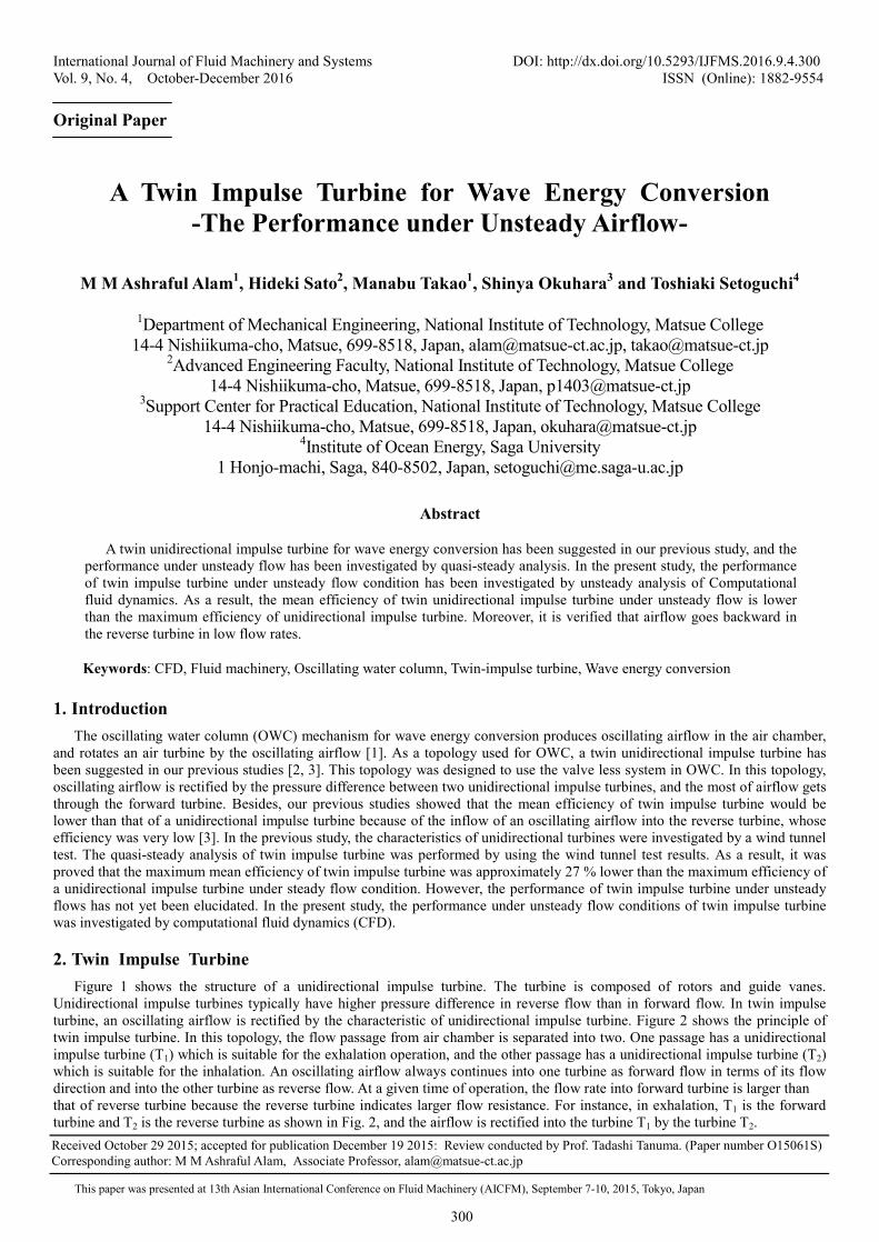
Unidirectional impulse turbines typically have higher pressure difference in reverse flow than in forward flow. In twin impulse turbine, an oscillating airflow is rectified by the characteristic of unidirectional impulse turbine. Figure 2 shows the principle of twin impulse turbine. In this topology, the flow passage from air chamber is separated into two. One passage has a unidirectional impulse turbine (T1) which is suitable for the exhalation operation, and the other passage has a unidirectional impulse turbine (T2) which is suitable for the inhalation. An oscillating airflow always continues into one turbine as forward flow in terms of its flow direction and into the other turbine as reverse flow. At a given time of operation, the flow rate into forward turbine is larger than that of reverse turbine because the reverse turbine indicates larger flow resistance. For instance, in exhalation, T1 is the forward turbine and T2 is the reverse turbine as shown in Fig. 2, and the airflow is rectified into the turbine T1 by the turbine T2. Received October 29 2015; accepted for publication December 19 2015: Review conducted by Prof. Tadashi Tanuma. (Paper number O15061S) Corresponding author: M M Ashraful Alam, Associate Professor, [email protected]
This paper was presented at 13th Asian International Conference on Fluid Machinery (AICFM), September 7-10, 2015, Tokyo, Japan
301
Fig. 1 Unidirectional impulse turbine
(a) Exhalation (b) Inhalation
Fig. 2 Principle of twin impulse turbine
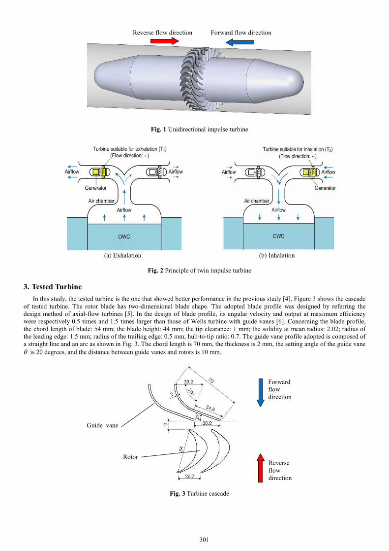
3. Tested Turbine In this study, the tested turbine is the one that showed better performance in the previous study [4]. Figure 3 shows the cascade
of tested turbine. The rotor blade has two-dimensional blade shape. The adopted blade profile was designed by referring the design method of axial-flow turbines [5]. In the design of blade profile, its angular velocity and output at maximum efficiency were respectively 0.5 times and 1.5 times larger than those of Wells turbine with guide vanes [6]. Concerning the blade profile, the chord length of blade: 54 mm; the blade height: 44 mm; the tip clearance: 1 mm; the solidity at mean radius: 2.02; radius of the leading edge: 1.5 mm; radius of the trailing edge: 0.5 mm; hub-to-tip ratio: 0.7. The guide vane profile adopted is composed of a straight line and an arc as shown in Fig. 3. The chord length is 70 mm, the thickness is 2 mm, the setting angle of the guide vane q is 20 degrees, and the distance between guide vanes and rotors is 10 mm.
Fig. 3 Turbine cascade
Reverse flow direction Forward flow direction
Guide vane
Rotor Reverse flow direction
Forward flow direction
302
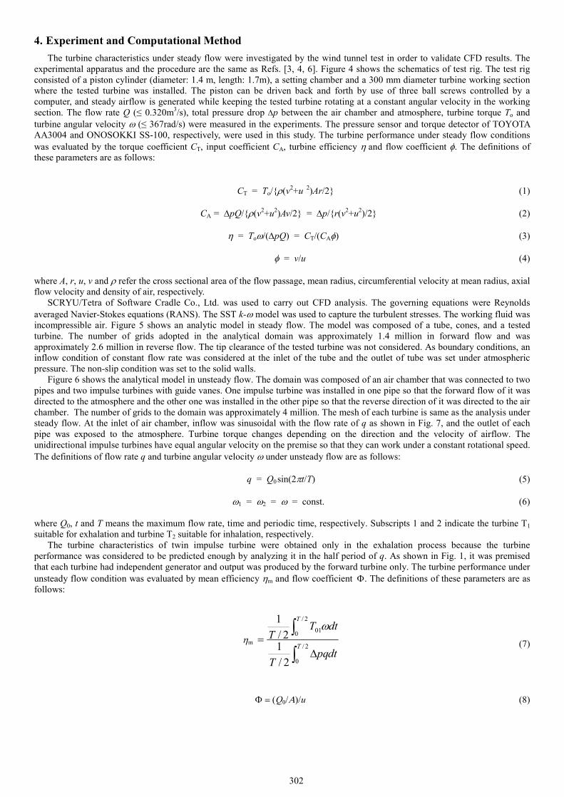
4. Experiment and Computational Method The turbine characteristics under steady flow were investigated by the wind tunnel test in order to validate CFD results. The
experimental apparatus and the procedure are the same as Refs. [3, 4, 6]. Figure 4 shows the schematics of test rig. The test rig consisted of a piston cylinder (diameter: 1.4 m, length: 1.7m), a setting chamber and a 300 mm diameter turbine working section where the tested turbine was installed. The piston can be driven back and forth by use of three ball screws controlled by a computer, and steady airflow is generated while keeping the tested turbine rotating at a constant angular velocity in the working section. The flow rate Q (≤ 0.320m3/s), total pressure drop Dp between the air chamber and atmosphere, turbine torque To and turbine angular velocity w (≤ 367rad/s) were measured in the experiments. The pressure sensor and torque detector of TOYOTA AA3004 and ONOSOKKI SS-100, respectively, were used in this study. The turbine performance under steady flow conditions was evaluated by the torque coefficient CT, input coefficient CA, turbine efficiency h and flow coefficient f. The definitions of these parameters are as follows:
CT = To/{r(v2+u 2)Ar/2} (1)
CA = DpQ/{r(v2+u2)Av/2} = Dp/{r(v2+u2)/2} (2)
h = Tow/(DpQ) = CT/(CAf) (3)
f = v/u (4)
where A, r, u, v and r refer the cross sectional area of the flow passage, mean radius, circumferential velocity at mean radius, axial flow velocity and density of air, respectively.
SCRYU/Tetra of Software Cradle Co., Ltd. was used to carry out CFD analysis. The governing equations were Reynolds averaged Navier-Stokes equations (RANS). The SST k-w model was used to capture the turbulent stresses. The working fluid was incompressible air. Figure 5 shows an analytic model in steady flow. The model was composed of a tube, cones, and a tested turbine. The number of grids adopted in the analytical domain was approximately 1.4 million in forward flow and was approximately 2.6 million in reverse flow. The tip clearance of the tested turbine was not considered. As boundary conditions, an inflow condition of constant flow rate was considered at the inlet of the tube and the outlet of tube was set under atmospheric pressure. The non-slip condition was set to the solid walls.
Figure 6 shows the analytical model in unsteady flow. The domain was composed of an air chamber that was connected to two pipes and two impulse turbines with guide vanes. One impulse turbine was installed in one pipe so that the forward flow of it was directed to the atmosphere and the other one was installed in the other pipe so that the reverse direction of it was directed to the air chamber. The number of grids to the domain was approximately 4 million. The mesh of each turbine is same as the analysis under steady flow. At the inlet of air chamber, inflow was sinusoidal with the flow rate of q as shown in Fig. 7, and the outlet of each pipe was exposed to the atmosphere. Turbine torque changes depending on the direction and the velocity of airflow. The unidirectional impulse turbines have equal angular velocity on the premise so that they can work under a constant rotational speed. The definitions of flow rate q and turbine angular velocity w under unsteady flow are as follows:
q = Q0 sin(2pt/T) (5)
w1 = w2 = w = const. (6) where Q0, t and T means the maximum flow rate, time and periodic time, respectively. Subscripts 1 and 2 indicate the turbine T1 suitable for exhalation and turbine T2 suitable for inhalation, respectively.
The turbine characteristics of twin impulse turbine were obtained only in the exhalation process because the turbine performance was considered to be predicted enough by analyzing it in the half period of q. As shown in Fig. 1, it was premised that each turbine had independent generator and output was produced by the forward turbine only. The turbine performance under unsteady flow condition was evaluated by mean efficiency hm and flow coefficient F. The definitions of these parameters are as follows:
(7)
F = (Q0/A)/u (8)
hm
dtpqT
dtTT
T
T
ò
òD
=2/
0
2/
0 01
2/1
2/1 w
303
Fig. 4 Test apparatus
Fig. 5 Analytical model for steady flow
Fig. 6 Analytical model for unsteady flow
Fig. 7 Sinusoidal flow rate
Inhalation
Exhalation
T1
T2
304
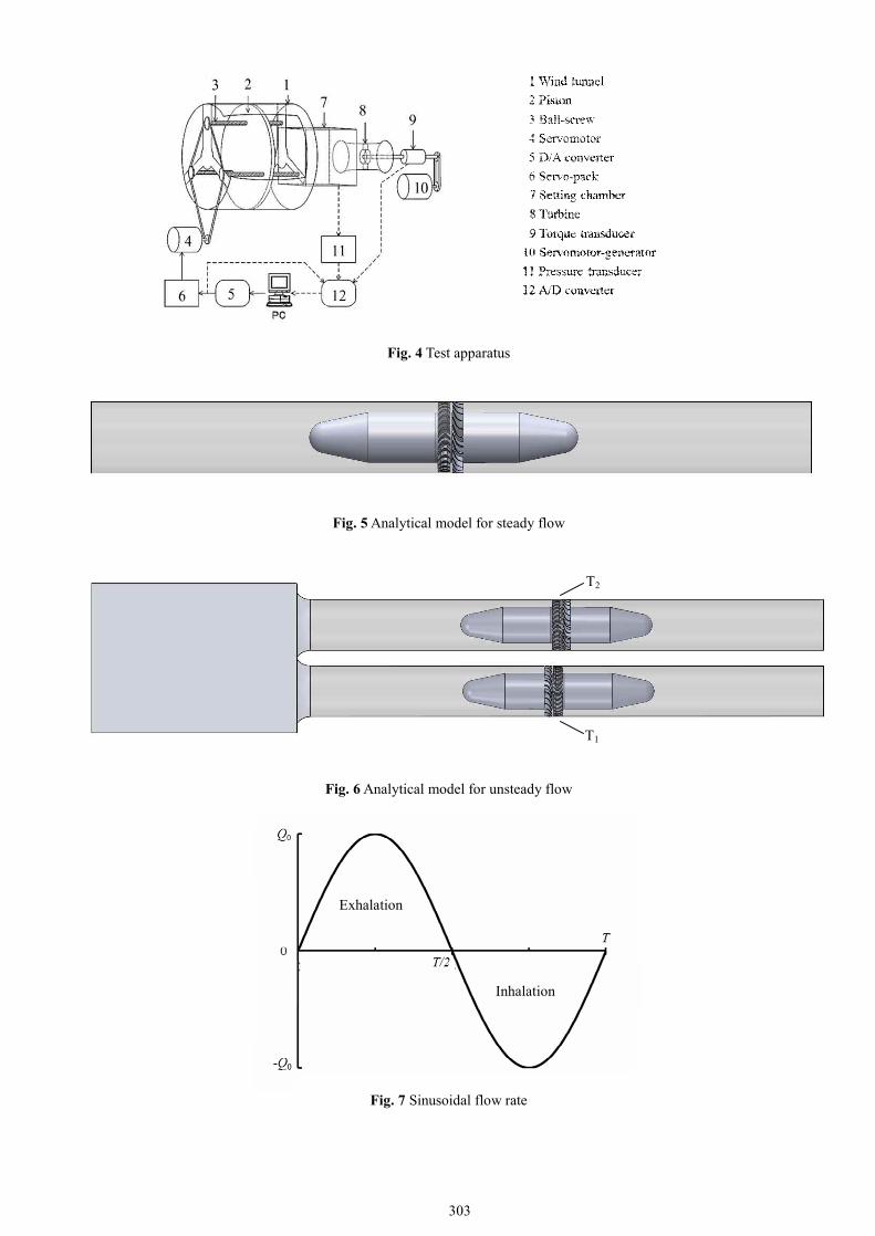
5. Results and Discussion Figure 8 shows the comparison of the turbine characteristics obtained from experiments and CFD analysis under steady flow
in forward and reverse flows. In Fig. 8, subscripts “f” and “r” to CA denote the forward and reverse flows, respectively. The difference of input coefficients between experiments and analysis gradually gets larger with the flow coefficient in both forward and reverse flows, as shown in Fig. 8 (a). However, the difference of input coefficients is not so large in a low flow coefficient. The torque coefficient is plotted against flow coefficient in Fig. 8(b) and it shows the same tendency like input coefficients. On the other hand, the turbine efficiencies from experiments and analysis are matched well in the whole flow range. Hence, the adopted CFD model is valid well relatively in a low coefficient.
Previous quasi-steady analysis shows that approximately 60 % of the total flow rate gets through forward turbine at the maximum efficiency [3]. In the present study, the mean efficiency is obtained on the premise that 60% of Q0 gets through the forward turbine, which has maximum efficiency. Table 1 shows the comparison of the mean efficiency hm of twin impulse turbine and the peak efficiency hp of unidirectional impulse turbine. The hm is approximately 27% lower than the hp.
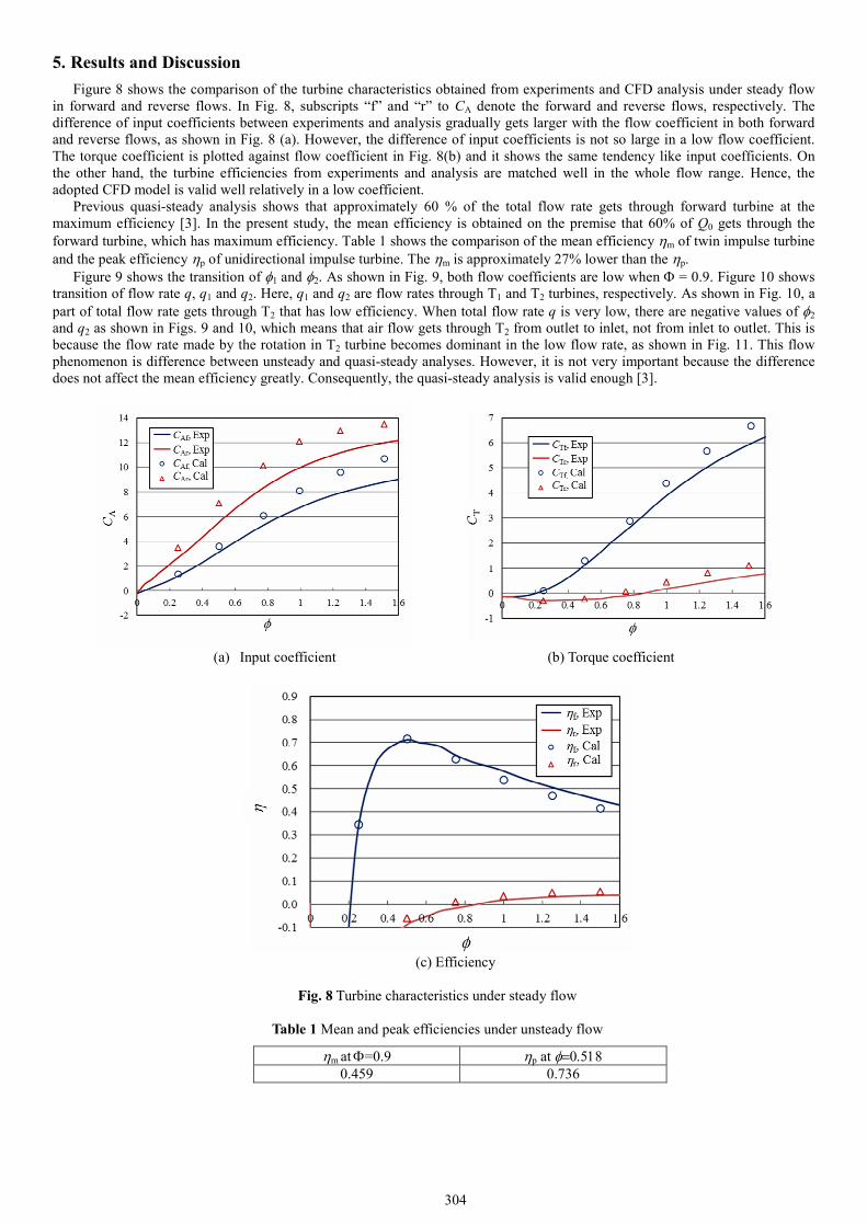
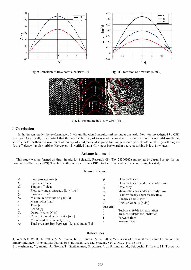
Figure 9 shows the transition of f1 and f2. As shown in Fig. 9, both flow coefficients are low when F = 0.9. Figure 10 shows transition of flow rate q, q1 and q2. Here, q1 and q2 are flow rates through T1 and T2 turbines, respectively. As shown in Fig. 10, a part of total flow rate gets through T2 that has low efficiency. When total flow rate q is very low, there are negative values of f2 and q2 as shown in Figs. 9 and 10, which means that air flow gets through T2 from outlet to inlet, not from inlet to outlet. This is because the flow rate made by the rotation in T2 turbine becomes dominant in the low flow rate, as shown in Fig. 11. This flow phenomenon is difference between unsteady and quasi-steady analyses. However, it is not very important because the difference does not affect the mean efficiency greatly. Consequently, the quasi-steady analysis is valid enough [3].
(a) Input coefficient (b) Torque coefficient
(c) Efficiency
Fig. 8 Turbine characteristics under steady flow
Table 1 Mean and peak efficiencies under unsteady flow
hm at F=0.9 hp at f=0.518 0.459 0.736
305
Fig. 9 Transition of flow coefficient (F=0.9) Fig. 10 Transition of flow rate (F=0.9)
Fig. 11 Streamline in T2 (t = 2.987 [s])
6. Conclusion In the present study, the performance of twin unidirectional impulse turbine under unsteady flow was investigated by CFD
analysis. As a result, it is verified that the mean efficiency of twin unidirectional impulse turbine under sinusoidal oscillating airflow is lower than the maximum efficiency of unidirectional impulse turbine because a part of total airflow gets through a low-efficiency impulse turbine. Moreover, it is verified that airflow goes backward in a reverse turbine in low flow rates.
Acknowledgment This study was performed as Grant-in-Aid for Scientific Research (B) (No. 24360362) supported by Japan Society for the
Promotion of Science (JSPS). The third author wishes to thank JSPS for their financial help in conducting this study.
Nomenclature
References [1] Wan Nik, W. B., Muzathik A. M., Samo, K. B., Ibrahim M. Z., 2009 “A Review of Ocean Wave Power Extraction; the primary interface,” International Journal of Fluid Machinery and Systems, Vol. 2, No. 2, pp.156-164. [2] Jayashankar, V., Anand, S., Geetha, T., Santhakumar, S., Kumar, V.J., Ravindran, M., Setoguchi, T., Takao, M., Toyota, K.
f Flow coefficient F Flow coefficient under unsteady flow h Efficiency hm Mean efficiency under unsteady flow hp Peak efficiency under steady flow r Density of air [kg/m3] w Angular velocity [rad/s] subscript 1 Turbine suitable for exhalation 2 Turbine suitable for inhalation f Forward flow r Reverse flow
A Flow passage area [m2] CA Input coefficient CT Torque efficient q Flow rate under unsteady flow [m/s3] Q Flow rate [m/s3] Q0 Maximum flow rate of q [m3/s] r Mean radius [mm] t Time [s] T Period [s] To Output torque [N·m] u Circumferential velocity at r [m/s] v Mean axial flow velocity [m/s] Dp Total pressure drop between inlet and outlet [Pa]

306
and Nagata, S., 2009, “A Twin Unidirectional Topology for OWC Based Wave Energy Plants,” Renewable Energy, Vol. 34, No. 3, pp. 692-698. [3] Takao, M., Takami, A., Okuhara, S. and Setoguchi, T., 2011, “A Twin Unidirectional Impulse Turbine for Wave Energy Conversion,” Journal of Thermal Science, Vol.20, No.5, pp.394-397. [4] Takao, M., Setoguchi, T., Kaneko, K., Kim, T. H., Maeda, H and Inoue, M., 2002 “Impulse Turbine for Wave Power Conversion with Air Flow Rectification System,” International Journal of Offshore and Polar Engineering, Vol.12, No.2, pp.142-146. [5] M. Hamajima, 1973, Gas Turbine – theory and design, Corona Publishing Co., Ltd., Tokyo, (in Japanese). [6] Setoguchi, T., Takao, M., Kaneko, K. and Inoue, M., 1998, “Effect of Guide Vanes on the Performance of a Wells Turbine for Wave Energy Conversion,” International Journal of Offshore and Polar Engineering, Vol.8, No.2, pp.155-160.