Embed Size (px)
Citation preview
A Unified Mobility Management Architecture A Unified Mobility Management Architecture A Unified Mobility Management Architecture A Unified Mobility Management Architecture
for Interworked Heterogeneous for Interworked Heterogeneous for Interworked Heterogeneous for Interworked Heterogeneous
Mobile NetworksMobile NetworksMobile NetworksMobile Networks
Kumudu S. Munasinghe
A thesis submitted in fulfillment of the requirements for the award of the degree
Doctor of Philosophy
to
The University of Sydney
on
September 2008

ii
Declaration
This is to certify that to the best of my knowledge and belief, the work presented in this thesis
is original, unless specified otherwise, and that no part of this material has been submitted,
either in full or in part, at this or any other institution.
----------------------------------------
Kumudu S. Munasinghe
September 2008
© 2008 by Kumudu S. Munasinghe
All rights reserved. No part of this thesis may be reproduced, in any form or by any means,
without permission in writing from the author.

iii
to Savithri, Amma, and Thaththa
with love
iv
Acknowledgements
The production of any thesis naturally requires valuable contributions, moral support, and
blessings of family and friends. First and foremost, I would like to thank my loving wife,
Savithri, respected parents, Sarath and Irani. It is through their immeasurable sacrifices,
encouragements, blessings, and prayers that I have been able to successfully complete this
thesis. With the deepest gratitude, I dedicate this thesis to them. I would also like to thank my
brother Chanaka, who has also been a great inspiration for this journey.
I am deeply indebted to my principle supervisor Professor Abbas Jamalipour for awarding
the Australian Postgraduate Award Industry (APAI) scholarship and being my guide and guru
throughout this amazing journey. Professor Jamalipour’s in-depth knowledge, unfailing advice,
and uplifting moral support helped me overcome many moments of depression and uncertainty
in this roller coaster ride. His constructive and continuous feedback immensely helped me in
formulating and crystallizing ideas. Furthermore, Prof. Jamalipour’s philosophy of scientific
research and the advice on the art of scientific writing, tremendously contributed towards the
production of this manuscript, several magnitudes beyond my expectations. I am also very
much obliged for the various additional financial assistantships (teaching and research)
provided to improve my financial stability, and thus making this a smoother journey.
Additionally, I would like to thank the academic staff of the School of Electrical and
Information Engineering for their stimulating suggestions and encouragements in improving
the quality of my work. Thanks also due to my dear colleagues, Ehssan, Rubaiyat, Mohammad,
Kingsley, Stephan, Kun, Srdjan, Fan, Hisyam, Ma, and Farshad for their friendship and support
during the stressful times.
Also, many thanks to the team of the Computer System Officers, David, Michael, and
Wesley for their immeasurable help and technical support. I would also like to thank the
School for the teaching assistantships provided and the Norman I Price Scholarship, which also
helped me financially sustain throughout my candidature. Last but not least my thanks go to the
Australian Research Council (ARC) and SingTel Optus Networks, the ARC Linkage project
partners for the financial support towards the scholarship and their constructive feedback.
MY HEARTFELT THANKS TO ALL!
v
Abstract
The buzzword of this decade has been convergence: the convergence of telecommunications,
Internet, entertainment, and information technologies for the seamless provisioning of
multimedia services across different network types. Thus the future Next Generation Mobile
Network (NGMN) can be envisioned as a group of co-existing heterogeneous mobile data
networking technologies sharing a common Internet Protocol (IP) based backbone. In such all-
IP based heterogeneous networking environments, ongoing sessions from roaming users are
subjected to frequent vertical handoffs across network boundaries.
Therefore, ensuring uninterrupted service continuity during session handoffs requires
successful mobility and session management mechanisms to be implemented in these
participating access networks. Therefore, it is essential for a common interworking framework
to be in place for ensuring seamless service continuity over dissimilar networks to enable a
potential user to freely roam from one network to another. For the best of our knowledge, the
need for a suitable unified mobility and session management framework for the NGMN has not
been successfully addressed as yet. This can be seen as the primary motivation of this research.
Therefore, the key objectives of this thesis can be stated as:
� To propose a mobility-aware novel architecture for interworking between heterogeneous
mobile data networks
� To propose a framework for facilitating unified real-time session management (inclusive of
session establishment and seamless session handoff) across these different networks.
In order to achieve the above goals, an interworking architecture is designed by
incorporating the IP Multimedia Subsystem (IMS) as the coupling mediator between dissipate
mobile data networking technologies. Subsequently, two different mobility management
frameworks are proposed and implemented over the initial interworking architectural design.
The first mobility management framework is fully handled by the IMS at the Application
Layer. This framework is primarily dependant on the IMS’s default session management
protocol, which is the Session Initiation Protocol (SIP). The second framework is a combined
vi
method based on SIP and the Mobile IP (MIP) protocols, which is essentially operated at the
Network Layer.
An analytical model is derived for evaluating the proposed scheme for analyzing the
network Quality of Service (QoS) metrics and measures involved in session mobility
management for the proposed mobility management frameworks. More precisely, these
analyzed QoS metrics include vertical handoff delay, transient packet loss, jitter, and signaling
overhead/cost. The results of the QoS analysis indicates that a MIP-SIP based mobility
management framework performs better than its predecessor, the Pure-SIP based mobility
management method. Also, the analysis results indicate that the QoS performances for the
investigated parameters are within acceptable levels for real-time VoIP conversations. An
OPNET based simulation platform is also used for modeling the proposed mobility
management frameworks. All simulated scenarios prove to be capable of performing successful
VoIP session handoffs between dissimilar networks whilst maintaining acceptable QoS levels.
Lastly, based on the findings, the contributions made by this thesis can be summarized as:
� The development of a novel framework for interworked heterogeneous mobile data
networks in a NGMN environment.
� The final design conveniently enables 3G cellular technologies (such as the Universal
Mobile Telecommunications Systems (UMTS) or Code Division Multiple Access 2000
(CDMA2000) type systems), Wireless Local Area Networking (WLAN) technologies, and
Wireless Metropolitan Area Networking (WMAN) technologies (e.g., Broadband Wireless
Access (BWA) systems such as WiMAX) to interwork under a common signaling
platform.
� The introduction of a novel unified/centralized mobility and session management platform
by exploiting the IMS as a universal coupling mediator for real-time session negotiation
and management.
� This enables a roaming user to seamlessly handoff sessions between different
heterogeneous networks.
� As secondary outcomes of this thesis, an analytical framework and an OPNET simulation
framework are developed for analyzing vertical handoff performance. This OPNET
simulation platform is suitable for commercial use.

vii
Publications Arising from the Thesis
Book Chapters
[1] K. S. Munasinghe and A. Jamalipour, “Mobility Management QoS Measures Evaluation
for Next Generation Mobile Networks,” in Wireless Communications: CNIT Thyrrenian
Symposium Series: Signals and Communications Technology, Ed. Pupolin Silvano,
USA: Springer, pp. 265-280, 2008.
Journal Articles
[1] K. S. Munasinghe and A. Jamalipour, An Analytical Evaluation of Mobility Management
in Integrated WLAN-UMTS Networks, Elsevier International Journal on Computers and
Electrical Engineering SI “Signal Processing and Communication Systems”, (Early
View).
[2] K. S. Munasinghe and A. Jamalipour, Interworked WiMAX-3G Cellular Networks: An
Architecture for Mobility Management and Performance Evaluation, IEEE Transactions
on Wireless Communications, (Early View).
[3] K. S. Munasinghe, M. Rubaiyat Kibria, and A. Jamalipour, Designing VoIP Session
Management over Interworked WLAN-3G Cellular Networks, in IEEE Wireless
Communications, vol. 15, no. 4, pp. 86-94, August 2008.
[4] K. S. Munasinghe and A. Jamalipour, Interworking of WLAN-UMTS Networks: An
IMS-based Platform for Session Mobility, in IEEE Communications, vol. 46, no.9, pp.
184-191 , September 2008.
Conference Proceedings
[1] K. S. Munasinghe and A. Jamalipour, Evaluation of Session Handoffs in a Heterogeneous
Mobile Network for Pareto based Call Arrivals, Accepted for publication in Proceedings
of the IEEE Wireless and Communications Conference (WCNC 2009), Budapest,
Hungary, April 2009 (in press).
[2] K. S. Munasinghe and A. Jamalipour, Analysis of Vertical Session Handoff for Self-
Similar Traffic in a Heterogeneous Mobile Data Network, in Proceedings of the
viii
International Conference on Signal Processing and Communication Systems (ICSPCS
2008), Gold Coast, Australia, December 2008.
[3] K. S. Munasinghe and A. Jamalipour, Analysis of Signaling Cost for a Roaming User in a
Heterogeneous Mobile Data Network, in Proceedings of the IEEE Global
Communications Conference (GLOBECOM 2008), New Orleans, USA, November 2008.
[4] K. S. Munasinghe and A. Jamalipour, An Architecture for Mobility Management in
Interworked 3G Cellular and WiMAX Networks, in Proceedings of the IEEE Wireless
Telecommunications Symposium (WTS 2008), Pomona, California, USA, April 2008.
[5] K. S. Munasinghe and A. Jamalipour, Analytical Modeling of IMS based Interworking in
Heterogeneous Mobile Data Networks, in Proceedings of the International Conference
on Signal Processing and Communication Systems (ICSPCS 2007), Gold Coast,
Australia, December 2007.
[6] K. S. Munasinghe and A. Jamalipour, A Unified Mobility and Session Management
Platform for Next Generation Mobile Networks, in Proceedings of the IEEE Global
Communications Conference (GLOBECOM 2007), Washington DC, USA, November
2007.
[7] K. S. Munasinghe and A. Jamalipour, Mobility Management QoS Measures Evaluation
for Next Generation Mobile Networks, in Proceedings of the Tyrrhenian Workshop on
Digital Communications (TIWDC 2007), Naples, Italy, September 2007.
[8] K. S. Munasinghe and A. Jamalipour, A 3GPP-IMS based Approach for Converging
Next Generation Mobile Data Networks, in Proceedings of the IEEE International
Conference on Communications (ICC 2007), Glasgow, Scotland, United Kingdom, June
2007.
[9] K. S. Munasinghe and A. Jamalipour, Interworking between WLAN and 3G Cellular
Networks: An IMS based Architecture, in Proceedings of the IEEE International
Conference on Wireless Broadband and Ultra Wideband Communications (AusWireless
2006), Sydney, Australia, March 2006.
ix
Technical Reports
[1] K. S. Munasinghe and A. Jamalipour, “WLAN-UMTS-CDMA2000 Interworking
Architectures,” Technical Report for Singtel Optus Networks, April 2007.
[2] K. S. Munasinghe and A. Jamalipour, “WLAN and 3G Cellular Network Interworking,”
Technical Report for SingTel Optus Networks, April 2006.
[3] K. S. Munasinghe and A. Jamalipour, “A Novel Architecture for WLAN and 3G Cellular
Network Interworking,” Technical Report for SingTel Optus Networks, November 2005.
[4] K. S. Munasinghe and A. Jamalipour, “Wireless LAN and Cellular Network
Interworking Architectures: Open issues and Research Themes,” Technical Report for
SingTel Optus Networks, August 2005.
x
Table of Contents
Declaration ...............................................................................................................ii
Acknowledgements .................................................................................................iv
Abstract ....................................................................................................................v
Publications Arising from the Thesis .................................................................... vii
List of Figures and Tables .................................................................................... xiii
Glossary of Acronyms and Abbreviations .......................................................... xvii
1 An Introduction to Interworking Heterogeneous Wireless Networks ..................1
1.1 Wireless Data Networks: An Overview .......................................................................1 1.1.1 Wireless Local Area Network (WLAN).................................................................................2 1.1.2 Wireless Metropolitan Area Network (WMAN)....................................................................3 1.1.3 Wireless Wide Area Network (WWAN) ................................................................................4
1.2 Interworking Trends and Issues....................................................................................5
1.3 Objectives .....................................................................................................................6
1.4 Approach ......................................................................................................................7
1.5 Contribution..................................................................................................................8
1.6 Outline of the Thesis ....................................................................................................8
1.7 Summary and Conclusions .........................................................................................10
2 Interworking of Heterogeneous Networks: Architectures, Issues, and Trends ..11
2.1 Introduction ................................................................................................................11
2.2 The Tight Coupling Architecture ...............................................................................13
2.3 The Loose Coupling Architecture ..............................................................................15
2.4 Peer-to-Peer Networking Architecture .......................................................................17
2.5 3GPP’s Approach to WLAN and Cellular Interworking ...........................................19
2.6 3GPP2’s Approach to WLAN and Cellular Interworking..........................................21
2.7 Interworking between other Disparate Networks.......................................................23 2.7.1 Interworking between UMTS and CDMA2000 system.......................................................23 2.7.2 Interworking between UMTS and WiMAX system .............................................................28 2.7.3 Interworking between WLAN and WiMAX system .............................................................28
2.8 IEEE 802.21 Media Independent Handover Services ................................................29
2.9 Open Issues and Research Themes.............................................................................32

xi
2.10 IMS: IP Multimedia Subsystem .................................................................................34 2.10.1 3GPP IMS Architecture .................................................................................................35
2.10.1.1 Call Session Control Functions..................................................................................................................36 2.10.1.2 Proxy CSCF................................................................................................................................................36 2.10.1.3 Interrogating CSCF ....................................................................................................................................37 2.10.1.4 Serving CSCF.............................................................................................................................................37 2.10.1.5 Home Subscriber Server ............................................................................................................................37 2.10.1.6 Media Gateway Control Function and Media Gateway ............................................................................38 2.10.1.7 IMS Related Protocols ...............................................................................................................................38 2.10.1.8 The Session Control Protocol: SIP ............................................................................................................38 2.10.1.9 Other Protocols...........................................................................................................................................39
2.10.2 3GPP2 IMS Architecture ...............................................................................................40
2.11 Summary and Conclusions .........................................................................................42
3 A Basic Framework for Interworking WLAN and UMTS Networks ................43
3.1 Introduction ................................................................................................................43
3.2 Architectural Framework............................................................................................44 3.2.1 Session Establishment ........................................................................................................46 3.2.2 Session Handoff: UMTS to WLAN .....................................................................................48 3.2.3 Session Retrieval: WLAN to UMTS....................................................................................51
3.3 Common Scenarios of Interworking ..........................................................................53 3.3.1 Scenario 1: Common Billing and Customer Care..............................................................53 3.3.2 Scenario 2: UMTS based Access Control and Charging ...................................................54 3.3.3 Scenario 3: Access to UMTS IMS-based Services..............................................................54 3.3.4 Scenario 4: Service Continuity ...........................................................................................54 3.3.5 Scenario 5: Seamless Continuity of Service .......................................................................55
3.4 Network Modeling......................................................................................................56 3.4.1 Simulation of Vertical Handoff...........................................................................................59 3.4.2 VoIP Session Management .................................................................................................61 3.4.3 Simulation Results ..............................................................................................................62
3.5 Analytical Modeling ...................................................................................................66 3.5.1 Handoff Delay ....................................................................................................................67 3.5.2 Packet Loss.........................................................................................................................70 3.5.3 Signaling Overhead/Cost....................................................................................................71
3.6 Performance Analysis.................................................................................................76
3.7 Summary and Conclusions .........................................................................................88
4 An Extended Framework for Interworking WLAN, UMTS and CDMA2000
Networks ............................................................................................................89
4.1 Introduction ................................................................................................................89
4.2 IMS based Mobility Management in 3G Cellular Networks......................................90
4.3 Architectural Considerations ......................................................................................91
4.4 The Interworking Architecture ...................................................................................95
4.5 Analytical Modeling .................................................................................................100
xii
4.5.1 Handoff Delay ..................................................................................................................100 4.5.2 Packet Loss.......................................................................................................................102 4.5.3 Signaling Overhead/Cost..................................................................................................102
4.6 Performance Analysis...............................................................................................104
4.7 Network Modeling and Results ................................................................................113
4.8 Summary and Conclusions .......................................................................................116
5 A Unified Framework for Interworking Heterogeneous Mobile Wireless
Networks ..........................................................................................................118
5.1 Introduction ..............................................................................................................118
5.2 WiMAX: Beyond the Radio Interface......................................................................120
5.3 Related Work............................................................................................................122
5.4 The Interworking Architecture .................................................................................123
5.5 Analytical Modeling .................................................................................................127 5.5.1 Handoff Delay ..................................................................................................................127 5.5.2 Packet Loss.......................................................................................................................129 5.5.3 Signaling Overhead/Cost..................................................................................................130
5.6 Performance Analysis...............................................................................................131
5.7 Network Modeling and Results ................................................................................138 5.7.1 Simulation Platform..........................................................................................................138 5.7.2 Simulation Results ............................................................................................................140
5.8 Summary and Conclusions .......................................................................................143
6 Summary, Conclusions, and Future Directions ................................................144
6.1 Thesis Summary and Conclusions............................................................................144
6.2 Future Directions ......................................................................................................147
Appenxix A: Delay Analysis for an M/M/1 Queuing Model ..............................149
A.1 Delay Analysis and Little’s Law ...................................................................................149
Appendix B: Delay Analysis for Self-Similar Traffic .........................................152
B.1 Introduction ..............................................................................................................152
B.2 Pareto/M/1 Queuing Model ......................................................................................153
B.3 Vertical Handoff Analysis ........................................................................................155 B.3.1 Handoff Delay ..................................................................................................................155 B.3.2 Packet Loss.......................................................................................................................158
B.4 Numerical Results ....................................................................................................159
xiii
List of Figures and Tables
Figures
Figure 2.1 A Reference Diagram Showing Tight and Loose Coupling Points.
Figure 2.2 WLAN–3G Integration with Tight Coupling: System Overview.
Figure 2.3 Tight Coupling Architecture: The New Interworking Components.
Figure 2.4 WLAN–3G Integration with Loose Coupling: With 3G Based Access Control
and Charging.
Figure 2.5 WLAN–3G Integration with Peer-to-Peer Coupling.
Figure 2.6 Non-Roaming 3GPP Reference Architecture.
Figure 2.7 Roaming Reference Architecture — 3GPP PS-Based Services Provided via the
(a) 3GPP Home Network and (b) 3GPP Visiting Network.
Figure 2.8 3GPP2’s Proposed CDMA2000-WLAN Interworking Architecture.
Figure 2.9 UMTS and CDMA2000 Interworking: MIPv4 based Approach.
Figure 2.10 Interworking IISA Architecture for 4G Networks.
Figure 2.11 An Interworking Architecture based on the Gateway Solution.
Figure 2.12 An Interworking Architecture based on the Dual-Stack Solution.
Figure 2.13 IEEE 802.21 Media Independent Handover Architecture.
Figure 2.14 The IP Multimedia Subsystem (IMS) Architecture.
Figure 2.15 The 3GPP2-IMS Architecture.
Figure 3.1 Architecture for WLAN-3G Cellular Internetworking.
Figure 3.2 IMS-SIP Based Session Handoff.
Figure 3.3 Vertical Handoff Scenarios for Overlapped and Non-Overlapped Coverage.
Figure 3.4 IMS-SIP Based Session Retrieval.
Figure 3.5 The New Attributes of the IMS CSCF (SIP Proxy Server).
Figure 3.6 The New Attributes of the SIP User Agent Client.
Figure 3.7 The OPNET Simulation Model.
Figure 3.8 Numbers of Active IMS-SIP Sessions (above) and Corresponding Application
Traffic Flow (below) during a make-before-break Handoff from UMTS to
WLAN.

xiv
Figure 3.9 Numbers of Active IMS-SIP Sessions (above) and Corresponding Application
Traffic Flow (below) during a Break-before-make type Handoff from WLAN to
UMTS.
Figure 3.10 Transient Packet Loss during Vertical Handoff.
Figure 3.11 End-to-End Delay and Jitter.
Figure 3.12 Timing Diagram for a UMTS-to-WLAN Session Handoff.
Figure 3.13 Relative Distances in Hops.
Figure 3.14 Vertical Handoff Delay vs. Number of Handoffs.
Figure 3.15 Packet loss for a UMTS-to-WLAN Handoff.
Figure 3.16 Packet loss for a WLAN-to-UMTS Handoff.
Figure 3.17 Variation of End-to-End Delay (Jitter).
Figure 3.18 Behavior of Jitter vs. Number of Handoffs.
Figure 3.19 Normalized Signaling Cost vs. Average Session Arrival Rate (λ calls/min).
Figure 3.20 P1 vs. Average Session Arrival Rate (λ calls/min).
Figure 3.21 P2 vs. Average Session Arrival Rate (λ calls/min).
Figure 3.22 Normalized Signaling Cost vs. Average Network Mobility Rate (η min-1).
Figure 3.23 P1 vs. Average Network Mobility Rate (η min-1).
Figure 3.24 P2 vs. Average Network Mobility Rate (η min-1).
Figure 3.25 Normalized Signaling Cost vs. CMR (λ constant).
Figure 3.26 Normalized Signaling Cost vs. CMR (η constant).
Figure 4.1 Interworking Architecture with MIP-SIP based Mobility Management.
Figure 4.2 MIP-SIP Signaling Framework.
Figure 4.3 Relative distances in hops.
Figure 4.4 Vertical handoff delay from UMTS-to-WLAN.
Figure 4.5 Vertical handoff delay from WLAN-to-UMTS.
Figure 4.6 Packet loss for a UMTS-to-WLAN handoff.
Figure 4.7 Packet loss for a WLAN-to-UMTS handoff.
Figure 4.9 Normalized Signaling Cost vs. Average Session Arrival Rate (λ).
Figure 4.10 Normalized Signaling Cost vs. Average Network Mobility Rate (η).
Figure 4.11 Normalized Signaling Cost vs. CMR (λ constant).
Figure 4.12 Normalized Signaling Cost vs. CMR (η constant).

xv
Figure 4.13 Transient packet loss comparison for UMTS-to-WLAN vertical handoff
for MIP-SIP and Pure-SIP mechanisms.
Figure 4.14 Transient packet loss comparison for WLAN-to-UMTS vertical handoff
for MIP-SIP and Pure-SIP mechanisms.
Figure 5.1 WiMAX Network Architecture.
Figure 5.2 The Extended Interworking Architecture.
Figure 5.3 UMTS-WLAN Session Handoff Signaling.
Figure 5.4 Relative distances in hops.
Figure 5.5 Vertical Handoff Delay vs. Number of Session Handoffs.
Figure 5.6 Transient Packet Loss vs. Number of Handoffs.
Figure 5.7 Jitter vs. Number of Handoffs.
Figure 5.8 Signaling Cost vs. Call-to-Mobility Rate (CMR).
Figure 5.9 Signaling Cost vs. η when µCi and λ are constant.
Figure 5.10 Signaling Cost vs. λ when µCi and η are constant.
Figure 5.11 OPNET 14.0 Simulation Model.
Figure 5.12 Transient Packet Loss for a UMTS-to-WiMAX Handoff.
Figure 5.13 Transient Packet Loss for a WiMAX-to-UMTS Handoff.
Figure 5.14 Transient Packet Loss Comparison for a UMTS-to-WiMAX Handoff and a
UMTS-to-WLAN Handoff.
Figure 5.15 Variation of Delay (Jitter) for a WiMAX-to-UMTS Handoff.
Figure A.1 Packet-Switching Network Delay.
Figure B.1 WiMAX-to-UMTS Handoff Delay vs. System Utilization.
Figure B.2 UMTS-to-WiMAX Handoff Delay vs. System Utilization.
Figure B.3 Transient Packet Loss vs. System Utilization.

xvi
Tables
Table 3.1. IMS Message Sizes and Parameter Values Used for Analysis.
Table 4.1. IMS-SIP Message Sizes and Parameter Values Used for Analysis.
Table 6.1. Summary of OPNET based Simulation Results.
Table 6.2. Summary of Analytically Modeled Results.
xvii
Glossary of Acronyms and Abbreviations
3G 3rd Generation
3GPP 3rd Generation Partnership Project
3GPP2 3rd Generation Partnership Project 2
3PCC Third-Party Call Control
4G 4th Generation
AAA Authentication, Authorization, and Accounting
AEN Access Edge Node
ASN Access Service Network
B2BUA Back-to-Back User Agent
BEN Border Edge Node
BS Base Stations
BSS Basic Service Set
BU Binding Update
BWA Broadband Wireless Access
CDMA Code Division Multiple Access
CMR Call-to-Mobility Ratio
CoA Care of Address
CS Circuit-Switched
CSCF Call State Control Functions
CSMA/CA Carrier Sense Multiple Access with Collision Avoidance
CSN Connectivity Services Network
DFS Dynamic Frequency Selection
DHCP Domain Host Configuration Protocol
DSSS Direct Sequence Spread Spectrum
ETSI European Telecommunications Standards Institute
FA Foreign Agent
FCC Federal Communications Commission
FHSS Frequency Hopping Spread Spectrum
FMIPv6 Fast Handover for Mobile IPv6

xviii
FTP File Transfer Protocol
GGSN Gateway GPRS Support Node
GIF GPRS Interworking Function
GPRS General Packet Radio Service
GSM Global System for Mobile communications
HA Home Agent
HiperMAN High Performance Radio Metropolitan Area Network
HLR Home Location Register
HSDPA High-Speed Downlink Packet Access
HTTP Hypertext Transfer Protocol
I-CSCF Interrogating-CSCF
IEEE Institute of Electrical and Electronic Engineers
IISA Integrated InterSystem Architecture
IMS IP Multimedia Subsystem
IMS-MGW IMS Media Gateway
IMT-2000 International Mobile Telecommunications 2000
IP Internet Protocol
ISM Industrial, Scientific, and Medical
ITU International Telecommunications Union
LLC Logical Link Control
LoS Line-of-Sight
MAC Media Access Control
MAP Mobility Anchor Point
MGCF Media Gateway Control Function
MICS Media Independent Command Service
MIES Media Independent Event Service
MIH Media Independent Handover
MIHF Media Independent Handover Function
MIIS Media Independent Information Service
MIMO Multiple-Input Multiple-Output
MIP Mobile IP
xix
MMD Multi Media Domain
MMS Multimedia Message Service
MN Mobile Node
MRFC Media Resource Function Controller
MRFP Media Resource Function Processor
MSS Mobile Subscriber Station
MVNO Mobile Virtual Network Operator
NAT Network Address Translation
NGMN Next Generation Mobile Network
NLOS Non-Line-of-Sight
NWG Network Working Group
OFDM Orthogonal Frequency Division Multiplexing
OFDMA Orthogonal Frequency Division Multiple Access
PCF Packet Control Function
P-CSCF Proxy-CSCF
PDCP Packet Data Convergence Protocol
PDF Probability Density Function
PDG Packet Data Gateway
PDN Packet Data Network
PDP Packet Data Protocol
PDS Packet Data Subsystem
PDSN Packet Data Serving Node
PDU Protocol Date Unit
PHY Physical
PLMN Public Land Mobile Network
PRACK Provisional Response ACKnowledgement
PS Packet-Switched
PSTN Public Switched Telephony Network
QoS Quality of Service
RA Routing Area
RTCP Real Time Control Protocol

xx
RTP Real Time Protocol
SC Single Carrier
SCC Seamless Connection Control
SCP Service Control Point
S-CSCF Serving-CSCF
SDP Session Description Protocol
SGSN Serving GPRS Support Node
SIP Session Initiation Protocol
SLA Service Level Agreements
SMC Short Message Centre
SMS Short Message Service
TCP Transmission Control Protocol
TIA Telecommunications Industry Standard
TMM Transform Matching Method
TPC Transmit Power Control
UAC User Agent Client
UAS User Agent Servers
UDP User Datagram Protocol
UMTS Universal Mobile Telecommunications System
UTRAN UMTS Terrestrial Radio Access Network
VoIP Voice over Internet Protocol
VGSN Virtual GPRS Support Node
WAF WLAN Adaptation Function
W-APN WLAN Access Point Name
W-CDMA Wideband Code Division Multiple Access
WIG WLAN Interworking Gateway
WiMAX Worldwide Interoperability for Microwave Access
WLAN Wireless Local Area Networks
WMAN Wireless Metropolitan Area Networks
WPAN Wireless Personal Area Networks
WWAN Wireless Wide Area Networks

Chapter 1 – An Introduction to Interworking Heterogeneous Wireless Networks
1
V{tÑàxÜ D An Introduction to Interworking Heterogeneous
Wireless Networks
The emergence of various radio access technologies and wireless data communication
networks over the past decade has revolutionized the entire telecommunications industry. By
and large, these wireless networking technologies can be categorized as Wireless Personal Area
Networks (WPAN), Wireless Local Area Networks (WLAN), Wireless Metropolitan Area
Networks (WMAN), and Wireless Wide Area Networks (WWAN), which have been widely
accepted as a convenient alternative to the conventional wired networks. The increasing
demand for ubiquitous high speed data access has resulted in widespread deployment of
heterogeneous wireless networking domains. However, in order to ensure anywhere anytime
wireless data access, roaming facilities between dissimilar networks must be in place, which is
also the primary requirement of an NGMN. Hence, there is growing demand for efficient
architectures and platforms for interworking heterogeneous wireless networks, which is the
primary motivation of this research. Therefore the aim of this Chapter is to establish the
objective and scope of this thesis. The remainder of this Chapter is organized as follows.
Firstly, an overview on wireless data networks is presented. Secondly, the basic concepts of
interworking and trends are introduced. Followed by this are the sections on the objectives,
approach, and contributions of the thesis. The Chapter concludes by presenting an outline of
the thesis, which briefly presents a summary of the forthcoming Chapters.
1.1 Wireless Data Networks: An Overview
The development of new wireless technologies and the increased user demand for ubiquitous
high speed data access has given rise to the rapid deployment of wireless networks such as
WWAN, WMAN, WLAN, and WPAN over the last decade. Despite the rapid growth of the
above mentioned networks, physical characteristics such as underlying radio access

Chapter 1 – An Introduction to Interworking Heterogeneous Wireless Networks
2
technologies, data rates, geographical coverage, and mobility support of each of these
technologies are highly diverse in nature. For example, a modern third generation (3G) cellular
network (considered under a WWAN) is capable of providing high speed mobility and
relatively large coverage, but has relatively lower data rates. On the other hand, a WLAN
supports relatively high data rates, but relatively smaller area of coverage with limited
mobility. Therefore, this section presents a brief overview about various wireless technologies
comprised in a typical NGMN.
1.1.1 Wireless Local Area Network (WLAN)
The Institute of Electrical and Electronic Engineers (IEEE) formed the 802.11 Work Group in
September 1990 with the objective of developing a standard for wireless LANs to operate on a
low-power unlicensed frequency range. The selected frequency range was the Industrial,
Scientific, and Medical (ISM) bands, either the 2.4 GHz band or the 5 GHz band, which was
set aside by the Federal Communications Commission (FCC). As a result, the first IEEE’s
802.11 standard was released in 1997 [1].
This standard addresses the Media Access Control (MAC) and Physical (PHY) standards
separately. The original PHY standard provides data rates of 1-2 Mbps and three fundamentally
different mechanisms of operation. They are namely: Infrared, 2.4 GHz Frequency Hopping
Spread Spectrum (FHSS), and 2.4 GHz Direct Sequence Spread Spectrum (DSSS). The task
assigned to the 802.11 MAC is to coordinate an access mechanism, which allows fair access to
the medium. Since wireless stations do not have the capability of detecting collisions, the IEEE
802.11 WLANs have an access method that made every effort to avoid collisions, which is
known as Carrier Sense Multiple Access with Collision Avoidance (CSMA/CA).
In 1999, the IEEE released a new PHY standard named the IEEE 802.11b [2]. This standard
is capable of providing higher bit rates up to 11 Mbps using DSSS within the 2.4 GHz range.
About the same time, IEEE released another PHY standard named IEEE 802.11a. It provides
bit rates up to 54 Mbps and operates on the 5 GHz range [3]. However, instead of using DSSS
as in the previous cases, IEEE 802.11a uses a new modulation method called Orthogonal
Frequency Division Multiplexing (OFDM). A later contribution (June 2003) to the family of
IEEE 802.11 PHY standards was the IEEE 802.11g standard, operating in the 2.4 GHz range
and using OFDM [4]. This works in the 2.4 GHz band (like IEEE 802.11b), but uses the same

Chapter 1 – An Introduction to Interworking Heterogeneous Wireless Networks
3
OFDM based transmission scheme as IEEE 802.11a and capable of providing maximum data
rates up to 54 Mbps.
The IEEE 802.11n is a much recently proposed amendment to the IEEE 802.11 wireless
networking standard to significantly improve network throughput over previous standards with
a significant increase in the raw data rate from 54 Mbps to a maximum of 600 Mbps [5]. The
IEEE 802.11n is built on previous IEEE 802.11 standards by adding Multiple-Input Multiple-
Output (MIMO) and channel-bonding operation to the PHY layer, and frame aggregation to the
MAC layer. Although the work on the IEEE 802.11n standard dates back to 2004, the draft is
yet to be finalized in March 2009 with possible publication in December 2009 [6].
Another amendment added to the IEEE 802.11 is the standard for Spectrum and Transmit
Power Management Extensions, which is known as IEEE 802.11h-2003 (or 802.11h) [7]. It
solves problems like interference with satellites and radar using the same 5 GHz frequency
band. The standard provides Dynamic Frequency Selection (DFS) and Transmit Power Control
(TPC) to the 802.11a MAC [8]. It has been integrated into the full IEEE 802.11-2007 standard.
1.1.2 Wireless Metropolitan Area Network (WMAN)
A WMAN provides network access to buildings through exterior antennas communicating with
central radio Base Stations (BS). Because wireless systems have the capacity to address broad
geographic areas without the costly infrastructure development required in deploying cable
links to individual sites, the technology may prove less expensive to deploy and may lead to
more ubiquitous broadband access [9].
The IEEE 802.16 Working Group is the IEEE group working on WMANs, in particular the
air interface for fixed broadband wireless access systems. The working group develops
standards and recommended practices to support the development and deployment of fixed
broadband wireless access systems. The first IEEE 802.16 standard was approved in December
2001. It delivered a standard for point to multipoint broadband wireless transmission in the 10-
66 GHz band, with only a Line-of-Sight (LoS) capability. It uses a Single Carrier (SC) PHY
standard [10].
The IEEE 802.16a was an amendment to the IEEE 802.16 and delivered a point to
multipoint capability in the 2-11 GHz band [11]. For this to be of use, it also required a non-
Chapter 1 – An Introduction to Interworking Heterogeneous Wireless Networks
4
line-of-sight (NLOS) capability, and the PHY standard was therefore extended to include
OFDM and Orthogonal Frequency Division Multiple Access (OFDMA). The IEEE 802.16a
was ratified in January 2003 and was intended to provide "last mile" fixed broadband access.
The IEEE 802.16c, a further amendment to the IEEE 802.16, delivered a system profile for the
10-66 GHz IEEE 802.16 standard [12].
In September 2003, a revision project called the IEEE 802.16d commenced with the aim to
align the standard with aspects of the European Telecommunications Standards Institute’s
(ETSI) High Performance Radio Metropolitan Area Network (HiperMAN) standard [13]. This
project concluded in 2004 with the release of IEEE 802.16-2004 which superseded the earlier
IEEE 802.16 documents, including the a/b/c amendments [14]. The IEEE 802.16e-2005 is an
amendment to the IEEE 802.16-2004 standard and is often referred to in shortened form as the
IEEE 802.16e. This new amendment introduced support for mobility, amongst other things and
called as Mobile Worldwide Interoperability for Microwave Access, which is better known as
“Mobile WiMAX” [15].
1.1.3 Wireless Wide Area Network (WWAN)
A WWAN essentially comprises of an umbrella of 3G cellular networking technologies such as
UMTS [16], General Packet Radio Service (GPRS) [17], CDMA2000 (i.e., CDMA2000
1xRTT [18], CDMA2000 EV-DO [19], and CDMA2000 EV-DV [20]).
Currently, the most common form of UMTS uses Wideband Code Division Multiple Access
(W-CDMA) as the underlying air interface. It is standardized by the 3rd Generation Partnership
Project (3GPP), and addresses the International Telecommunications Union’s (ITU)
International Mobile Telecommunications 2000 (IMT-2000) [21] requirements for 3G cellular
radio systems. UMTS supports up to 14.0 Mbps data transfer rates (theoretically) with High-
Speed Downlink Packet Access (HSDPA) [22], despite the fact that at the moment users in
deployed networks can expect a transfer rates of up to 384 kbps for UMTS Release 99
handsets, and 7.2 Mbps for HSDPA handsets in the downlink connection.
The 3rd Generation Partnership Project 2’s (3GPP2) CDMA2000 can be deployed in several
phases. The first phase, CDMA2000 1x, supports an average of 144 kbps packet data in a
mobile environment. The second release of 1x, called 1x-EV-DO supports data rates up to 2

Chapter 1 – An Introduction to Interworking Heterogeneous Wireless Networks
5
Mbps on a dedicated data carrier. Finally, 1x-EV-DV (which probably will rarely be deployed)
will support even higher peak rates, simultaneous voice and high-speed data, as well as
improved QoS mechanisms.
1.2 Interworking Trends and Issues
As mentioned earlier, the future NGMN can essentially be seen as a group of overlapping
heterogeneous mobile data networks that are interworked together [23],[24]. Therefore, the
integration of these dissimilar technologies using a common framework can enable a potential
user to freely roam from one network to another. Furthermore, seamless session handoff from
one network to another will also become a possibility.
The main benefits of interworking can be summarized as:
� Ability for catering bandwidth demands for high performance applications such as
multimedia, video, and teleconferencing,
� Provisioning of global mobility and service portability across heterogeneous networking
boundaries,
� Realization of an all-IP based packet switched telecommunications system with converged
voice and data capability,
� Realization of the future NGMN or 4G networking platform which supports ubiquitous
data services and very high data rates across heterogeneous networks, and
� Provisioning of always best connectivity to the subscriber (in an NGMN).
In the recent years, much research has been done in the area of interworking between
various wireless data networks such as WLAN, 3G Cellular (i.e., UMTS and CDMA2000),
WiMAX [25]. By and large, these internetworking architectures can be categorized as tight
coupling, loose coupling, and peer-to-peer networking (also referred as no-coupling) [26], [27].
The design concepts behind the categorization of these architectures can be summarized as
follows. In the tight coupling architecture, the WLAN is directly connected to the UMTS core
network. Thus the WLAN data traffic gets routed via the UMTS core network before reaching
the external Packet Data Networks (PDNs). Therefore, UMTS mobility management
techniques may be directly applied in this method. On the other hand, the loosely coupled
architecture exchanges signaling between the WLAN and the UMTS core network while the

Chapter 1 – An Introduction to Interworking Heterogeneous Wireless Networks
6
data flows via independent IP based networks. There are also other variants to this
internetworking architecture, which may require the data traffic to be routed via the UMTS
core network [28], [29]. Since the data traffic is routed directly via an IP network this method
may help avoiding a potential traffic bottleneck. Nevertheless, in this method, the handoffs are
less efficient and therefore real-time session mobility may not always be guaranteed [27].
Lastly, the peer-to-peer coupling framework can be described as coupling the 3G cellular
network and the WLAN as peers, which may also be argued to be a variant of the loose
coupling architecture [26]. In this case, a higher layer mobility management protocol such as
Mobile IP (MIP) could be used for provisioning mobility management [30]. However, due to
known deficiencies of the MIP protocol itself (i.e., the issue of triangular routing, conflict with
security frameworks of cellular systems, and so on), this may not be the best solution for
frequently roaming users.
Despite these recent attempts, many open and unresolved issues still exist in this area. The
first of which is the issue of session mobility across WLAN and UMTS networks. Efficient
ways to provide/enable seamless continuity of service across WLAN and 3G cellular networks
can be ranked as a top issue. Another important issue is to define a mechanism for data routing
in heterogeneous networks. Additionally, matching the QoS requirements and service
provisioning in such environments are other related issues. Therefore, there exists a need for
the development of an architecture capable of overcoming these challenges, which motivates
this work.
1.3 Objectives
The objective of this thesis is to propose a mobility-aware novel architecture for interworking
heterogeneous mobile data networks, which facilitates real-time session management including
session establishment and seamless session handoff across dissipate networks. This framework
must conveniently enable a 3G cellular technology (such as UMTS or CDMA2000 system), a
WLAN technology, and a WMAN technology (i.e., a WiMAX system) to interwork under a
common signaling platform. Therefore, a roaming user in such a heterogeneous network will
be controlled via a centralized common mobility management platform where terminal
mobility and session mobility is managed in a real-time environment. This framework will
Chapter 1 – An Introduction to Interworking Heterogeneous Wireless Networks
7
essentially exploit the IP Multimedia Subsystem (IMS) as a universal coupling mediator for
real-time session negotiation and management [31]. This thesis also analyses and simulates
vertical handoff performance measures such as delay, transient packet loss, jitter, and signaling
overhead/cost.
1.4 Approach
The approach used for achieving the above objectives can be explained in three main stages as
follows. Initially an in-depth review of the current literature published in the area was carried
out. This was essential for identifying the trends and issues, formulating the problem, and
defining the motivations.
The first stage of the research was to design and develop an initial framework for
interworking UMTS and WLAN systems (with limited mobility). This framework used the
IMS as a universal coupling mediator for real-time session negotiation and management. Since
the initial goal was merely to interwork between UMTS and WLAN systems and the design
was somewhat close to a loose coupling model, the 3GPP’s IMS became the natural candidate
for a coupling mediator. Along with this, the Session Initiation Protocol (SIP) was used as the
protocol for mobility and session management (since it is already used within the IMS for
session management). As a result, the initial architecture inherited a pure SIP-based mobility
management platform, which was fully controlled at the Application Layer.
The second stage of the research further extended the existing framework to be capable of
interworking between different 3G cellular technologies (i.e., UMTS and CDMA2000) and
WLAN. However, this required major architectural changes within the initial design. As a
result, the mobility management concepts used in the 3GPP2’s core network and the 3GPP2
IMS framework were adopted. However, at this stage, it became obvious that re-designing of
the entire mobility management framework was necessary. Therefore, instead of having a pure
SIP-based mobility management framework, a MIP and SIP combined mobility management
framework was designed. Within this new framework, terminal/IP mobility is managed at the
network layer by MIP and session mobility is handled by SIP at the application layer.
The third and the last stage of the research further extended the model to interwork between
3G cellular, WLAN, and BWA (WiMAX) networks. Similar to the second stage, terminal/IP
Chapter 1 – An Introduction to Interworking Heterogeneous Wireless Networks
8
mobility was managed at the network layer by MIP and session mobility was handled by SIP at
the application layer. Since the default mobility management protocol for mobile WiMAX
networks was MIP, major modifications were not required for the initial mobility management
framework. Therefore, it can now be said that the final design is capable of interworking with a
variety of heterogeneous mobile networks, and thus proposes a suitable platform for a NGMN
or a 4G network [32].
An analytical model was derived for evaluating the proposed scheme for analyzing the
performance of QoS metrics and measures involved in call or session mobility management.
Furthermore, an OPNET based simulation platform was also used for modeling the proposed
interworking architectures.
1.5 Contribution
This thesis proposes two novel interworking architectures and mobility management
frameworks capable of providing session and terminal mobility for a roaming user in a NGMN.
The thesis also provides a reliable analytical model for evaluating the performance of such
heterogeneous networks. The introduction of the OPNET based interworking platform can also
be a considered as a commercially useful tool for simulating similar interworked scenarios
under controlled environments. The presented performance results (i.e., vertical handoff delay,
transient packet loss, and jitter) can be used by network designers as a performance guideline
or a bench mark for evaluating similar scenarios. Furthermore, these results can also be used by
application designers/providers and Telco’s for fine tuning their application parameters for
achieving optimal QoS levels and reliability over a heterogeneous wireless networking
environment.
1.6 Outline of the Thesis
This thesis is organized in such a way that it initially introduces different wireless data
communication networks (i.e., WLAN, WMAN, and WWAN) to the reader and explains the
growing possibility of experiencing the presence of more than one wireless network at a given
geographical location. Thus the reader is gradually exposed to the concept of the NGMN and

Chapter 1 – An Introduction to Interworking Heterogeneous Wireless Networks
9
the benefits of roaming between such dissimilar wireless networks. Once the motivations are
clarified for this research the objectives, approach, and contribution are clearly specified.
This section intends to provide a general overview of the forthcoming Chapters of this thesis
with the relevant corresponding publications. Each Chapter starts with a brief introduction to
its contents and ends with a summary and conclusion outlining the main topics discussed with
additional ending remarks. A complete set of references is cited at the end of the thesis with the
most relevant literature for the reader’s easy access.
Chapter 2 provides an in-depth discussion on the current architectures, future trends, and
research issues in relation to interworked heterogeneous mobile data networks. The discussion
begins by introducing the current and the most notable interworking architectures. The next
section presents the open issues and research trends. This Chapter concludes by introducing the
IMS and establishing its importance as a coupling media for the newly proposed interworking
architectures. The contents presented in this Chapter are partly generated from [33], [34].
Chapter 3 introduces an initial interworking architecture with the IMS as a universal
coupling mediator for real-time session negotiation and management. This initial model was
aimed for interworking UMTS and WLAN systems with limited mobility. The mobility
management framework proposed in this Chapter is fully dependant on the IMS, and its session
management protocol. Subsequently, a Queuing Theory based analytical model is introduced
for analyzing its vertical handoff performance and an OPNET based test bed is introduced for
simulating the architectural design. The interworking architecture and the OPNET simulation
platform presented in this Chapter is generated from [35], the basic introduction to the
analytical model is obtained from [36] and [37], the extended analysis using the Queuing
Theory is generated from [38], and lastly the signaling cost analysis method is generated form
[39].
Chapter 4 focuses on extending the proposed WLAN-UMTS interworking architecture
presented in Chapter 3 to a unified framework for interworking dissimilar 3G cellular
networking standards. As a result, global roaming and interoperability beyond one cellular
system (say, UMTS) to another cellular system (say, CDMA2000) becomes possible.
Subsequently the sections on analytical modeling and performance evaluations are presented.
Finally an OPNET based simulation model is introduced for validation. The interworking
Chapter 1 – An Introduction to Interworking Heterogeneous Wireless Networks
10
architecture and the OPNET simulation platform presented in this Chapter is generated from
[40] and the OPNET simulation results are partly obtained from [41] and [42].
Chapter 5 further extends the proposed interworking architecture in to a unified mobility
and session management framework for interworking heterogeneous mobile and wireless
networks. More specifically, this Chapter introduces interworking BWA networks (such as
WiMAX) with the existing platform. Therefore, the proposed platform will not only be capable
of providing global roaming between multiple cellular systems, but also be able to successfully
interwork with WLAN and WiMAX networks, thus creating a truly seamless inter-network
roaming experience for the user. The interworking architecture and the analytical model
presented in this Chapter is generated from [43] and the OPNET simulation results are partly
obtained from [44]. Finally, Chapter 6 presents the concluding remarks for this thesis by
summarizing the important conclusions based on the overall results of the research.
1.7 Summary and Conclusions
The purpose of this Chapter was to expose the reader to the concept of the NGMN or the 4G
Networks. Subsequently the reader was introduced to different wireless data communication
networks (i.e., WLAN, WMAN, and WWAN) and established the growing possibility of
experiencing the presence of more than one wireless network at a given time and a
geographical location. Followed by this, the importance of roaming between such dissimilar
wireless networks was explained. Once the motivations were clarified for this research the
objectives, approach, and contribution was clearly specified. Finally, an outline of the thesis is
briefly presented, which was an outline of the forthcoming Chapters.

Chapter 2 – Interworking Heterogeneous Networks: Architectures, Issues, and Trends
11
V{tÑàxÜ E Interworking of Heterogeneous Networks:
Architectures, Issues, and Trends
This Chapter provides an in-depth discussion on the current architectures, research issues, and
future trends on interworking heterogeneous mobile data networks. The discussion begins by
introducing the current and the most notable interworking architectures and relating design
issues. This Chapter also discusses the open issues and research trends in interworking and
introduces the IMS as a potential coupling media for interworking dissimilar networks. The
organization of this Chapter can be outlined as follows. Firstly the reader is introduced to the
concept and benefits of interworking heterogeneous networks. Then the main flavours and
standards/specifications of interworking architectures are introduced. Subsequently, the
sections on the IEEE 802.21 Media Independent Handover and the IMS follow prior to the
concluding remarks. The contents presented in this Chapter have contributed to [33] and [34].
2.1 Introduction
Modern cellular networks are capable of providing better mobility, whereas WLANs are
known for their relatively higher bandwidth. Ubiquitous data services and very high data rates
across heterogeneous networks may be achieved by the use of a WLAN as a complementary
technology to cellular data networks. Hence there is a strong need for efficient interworking
mechanisms between WLANs and cellular data networks [45]. These interworking
mechanisms, are expected to be equipped with integrated authentication, integrated billing,
roaming, terminal mobility, and service mobility [25],[46]. A variety of interworking
architectures have been proposed by numerous researchers and groups. By and large, these
proposed integration architectures can be categorized as tight coupling, loose coupling, and
Chapter 2 – Interworking Heterogeneous Networks: Architectures, Issues, and Trends
12
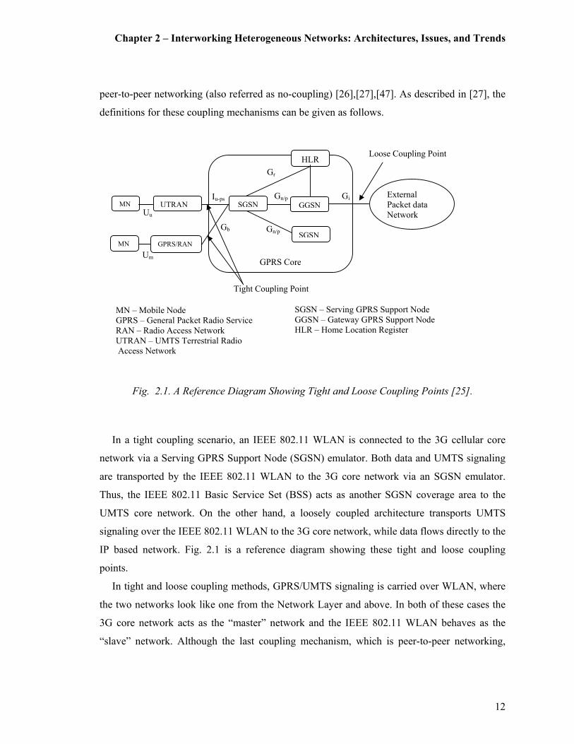
peer-to-peer networking (also referred as no-coupling) [26],[27],[47]. As described in [27], the
definitions for these coupling mechanisms can be given as follows.
Fig. 2.1. A Reference Diagram Showing Tight and Loose Coupling Points [25].
In a tight coupling scenario, an IEEE 802.11 WLAN is connected to the 3G cellular core
network via a Serving GPRS Support Node (SGSN) emulator. Both data and UMTS signaling
are transported by the IEEE 802.11 WLAN to the 3G core network via an SGSN emulator.
Thus, the IEEE 802.11 Basic Service Set (BSS) acts as another SGSN coverage area to the
UMTS core network. On the other hand, a loosely coupled architecture transports UMTS
signaling over the IEEE 802.11 WLAN to the 3G core network, while data flows directly to the
IP based network. Fig. 2.1 is a reference diagram showing these tight and loose coupling
points.
In tight and loose coupling methods, GPRS/UMTS signaling is carried over WLAN, where
the two networks look like one from the Network Layer and above. In both of these cases the
3G core network acts as the “master” network and the IEEE 802.11 WLAN behaves as the
“slave” network. Although the last coupling mechanism, which is peer-to-peer networking,
Um
Uu
Gb
Iu-ps
Gn/p
Gn/p Gi
Gr
SGSN GGSN
HLR
SGSN
UTRAN
GPRS/RAN
MN
MN
External
Packet data
Network
GPRS Core
Tight Coupling Point
MN – Mobile Node
GPRS – General Packet Radio Service
RAN – Radio Access Network
UTRAN – UMTS Terrestrial Radio
Access Network
SGSN – Serving GPRS Support Node
GGSN – Gateway GPRS Support Node
HLR – Home Location Register
Loose Coupling Point

Chapter 2 – Interworking Heterogeneous Networks: Architectures, Issues, and Trends
13
may be seen as an extension to the loose coupling architecture, it treats the two networks as
peers [26]. MIP is used to provide a framework for mobility among these peers. Last but not
least, there are also other various proposals of hybrid coupling schemes [48]. Such methods are
capable of differentiating the data and signaling paths according to the type of traffic. For
example, in the case of [48], a tightly coupled architecture is used for real-time traffic, and a
loosely coupled network architecture is used for non-real time and bulky traffic.
2.2 The Tight Coupling Architecture
As mentioned previously, in tight coupling, the WLAN is directly connected to the 3G cellular
core network [49]. Fig. 2.2 illustrates a basic system configuration diagram for a tight coupling
architecture. Thus the WLAN data traffic passes through the GPRS core network before
reaching the external PDNs.
The key functional element in the system is the GPRS Interworking Function (GIF), which
interconnects an IEEE 802.11 Extended Service Set (ESS) to a SGSN via the standard Gb
interface [25]. This is also referred to as an SGSN emulator [27]. The GIF is the function that
makes the SGSN consider the WLAN as a typical GPRS Routing Area (RA) composed of only
one cell.
The handover between the WLAN and the GPRS can be considered as a handover between
two individual cells. It is also worth noting that the GIF and all interconnected WLAN
terminals use a 48-bit IEEE 802 MAC address. The WLAN Adaptation Function (WAF) is the
main component, which helps the Mobile Node (MN) to identify the MAC address of the GIF
(Fig. 2.3). Hence, there is a WAF implemented in every dual mode MN as well as the GIF for
3G signaling and data exchange over the IEEE 802.11 WLAN. The WAF also provides the
following functions:
� Signaling the activation of WLAN interface as the MS enters a WLAN area,
� Discovering the MAC address of the GIF,
� Helping the SGSN page a mobile station over the Gb interface,
� Transferring Logical Link Control (LLC) Protocol Data Units (PDU) from mobile station
to the GIF and vice-versa, and
� Supporting QoS by implementing transmission scheduling in the GFS and the MN.

Chapter 2 – Interworking Heterogeneous Networks: Architectures, Issues, and Trends
14
Dual-mode MN
LLC
WLAN
Adaptation
Function
(WAF)
WLAN
Radio
subsystem
GPRS
Radio
subsystem
GPRS
Access
Network
WLAN
Access
Network
GPRS
Interworking
Function
(GIF)
GPRS
Core
Network
Gb
Gb
Um
WLAN access network
Defined by 802.11
New interworking components
Fig. 2.2. WLAN–3G Integration with Tight Coupling: System Overview [25].
Fig.2.3. Tight Coupling Architecture: The New Interworking Components [25].
Gb
GGSN SGSN
802.11 Extended Service Set (ESS)
GIF
Dual
Mode
MN
UTRAN/
GPRS
RAN
GPRS Core
IP Network
AP
BSS-3 BSS-1 BSS-2
MN – Mobile Node
GIF – GPRS Interworking
Function
GPRS – General Packet
Radio Service
RAN – Radio Access
Network
UTRAN – UMTS Terrestrial
Radio Access Network
SGSN – Serving GPRS
Support Node
GGSN – Gateway GPRS
Support Node
BSS – Basic Service Set
AP – Access Point
Chapter 2 – Interworking Heterogeneous Networks: Architectures, Issues, and Trends
15
Additionally, the tight coupling architecture can be conveniently extended by adding new
functionalities such as location based service support by enabling efficient support for location
aware secure fast roaming with location privacy control functions and a location based policy
authority [50].
Since the WLAN and GPRS networks connect to the same Gateway GPRS Support Node
(GGSN), IP addresses are assigned by the same pool. Hence, the mobility across the two
networks do not require a change of an IP address [27]. Lastly, a tight coupling architecture
provides the following benefits [25]:
� Seamless service continuation across WLAN and 3G networks,
� Less complicated mobility management mechanisms (since it follows GPRS/UMTS
mobility management mechanisms),
� Ability to use the GPRS/UMTS Authentication, Authorization, and Accounting (AAA)
system,
� Ability to use the GPRS/UMTS infrastructure for routing (e.g., core network resources,
subscriber database, billing systems),
� Increased security (GPRS/UMTS security can be applied on top of WLAN security),
� Common provisioning and customer care, and
� Access to core GPRS/UMTS services (Short Message Service (SMS), location-based
service, Multimedia Message Service (MMS), etc.)
However, it is important to note that, the tight coupling architecture is primarily designed
for WLANs owned by cellular operators [51]. Thus it lacks implementation capability for
third-party WLANs. Further, there are cost and capacity concerns associated with the
connection of a WLAN to an SGSN.
2.3 The Loose Coupling Architecture
Similar to the previous coupling method, loose coupling architecture is also a master/slave
framework. As shown in Fig. 2.4, the GPRS network acts as a master and the IEEE 802.11
WLAN acts as a slave network (or a visiting network) where only the AAA traffic is routed
through the 3G core network (not the user data traffic) [28] [52]. In this scenario, only AAA
signaling is exchanged between the WLAN and the 3G home Public Land Mobile Network

Chapter 2 – Interworking Heterogeneous Networks: Architectures, Issues, and Trends
16
(PLMN) (via the 3G visited PLMN) to provide authentication, authorization and accounting
(charging).
Two alternative authentication models (or flavors) for loose coupling can been identified in
the literature [53], [54]. These are described as the “IETF flavor” and the “UMTS flavor” [53].
The primary difference between these two is essentially the authentication server it self [54].
Fig. 2.4. WLAN–3G Integration with Loose Coupling: With 3G Based Access Control and
Charging [28].
During the authorization phase, the 3G AAA server can establish policies for the user data
traffic. It can also serve as a proxy to route AAA signaling to/from other 3G PLMNs (Fig. 2.4).
Thus the 3G AAA server is an important component introduced in the loosely coupled
interworking architectures. However, more advanced types of interworking scenarios (as
Internet
Internet
Operators
IP Network
WLAN
AAA
Proxy
3G AAA
Proxy
3G AAA
Server
HLR
SGSN GGSN
UTRAN
AP
WLAN
3G Visited Network
3G Home Network
AAA Traffic
AAA Traffic
Data Traffic
Data Traffic
MN – Mobile Node
AP – Access Point
WLAN – Wireless Local Area Network
UTRAN – UMTS Terrestrial Radio
Access Network
SGSN – Serving GPRS Support Node
GGSN – Gateway GPRS Support Node
HLR – Home Location Register
AAA – Authentication Authorizing and
Accounting
MN
Chapter 2 – Interworking Heterogeneous Networks: Architectures, Issues, and Trends
17
discussed later) may also require the user data traffic to be routed to the UMTS core network
[28], [29].
A clear advantage of the above method is that, since the data traffic is routed directly to and
from the IP network (Internet) without having to route through the 3G network, a potential
traffic bottleneck can be avoided. Since the 3G network and the WLAN are likely to be in
different IP address domains, the MN will be allocated an IP address from the pool of
addresses of the connected network. The changing of an IP address may result in loss of
connectivity. Therefore, in the loose coupling architecture, handoffs are less efficient and
mobility management is generally more complicated when the user is in an active session [27].
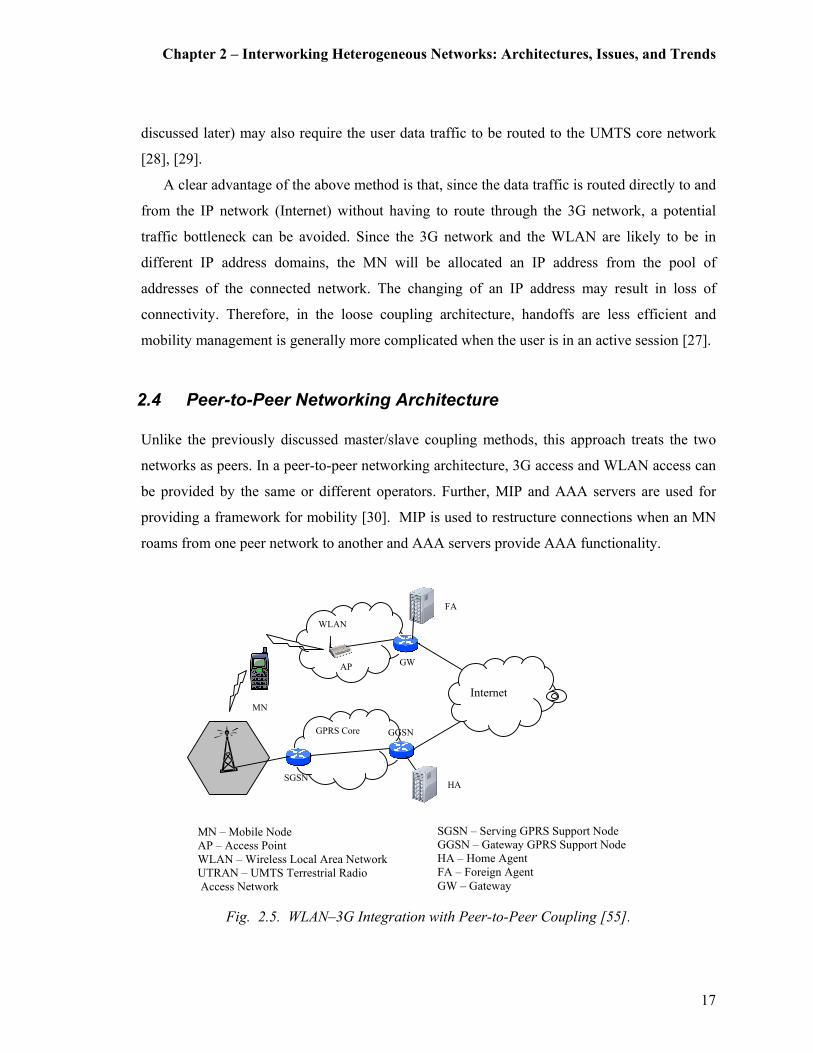
2.4 Peer-to-Peer Networking Architecture
Unlike the previously discussed master/slave coupling methods, this approach treats the two
networks as peers. In a peer-to-peer networking architecture, 3G access and WLAN access can
be provided by the same or different operators. Further, MIP and AAA servers are used for
providing a framework for mobility [30]. MIP is used to restructure connections when an MN
roams from one peer network to another and AAA servers provide AAA functionality.
Fig. 2.5. WLAN–3G Integration with Peer-to-Peer Coupling [55].
GPRS Core
Internet
WLAN
AP
GGSN
SGSN
FA
HA
MN – Mobile Node
AP – Access Point
WLAN – Wireless Local Area Network
UTRAN – UMTS Terrestrial Radio
Access Network
SGSN – Serving GPRS Support Node
GGSN – Gateway GPRS Support Node
HA – Home Agent
FA – Foreign Agent
GW – Gateway
MN
GW

Chapter 2 – Interworking Heterogeneous Networks: Architectures, Issues, and Trends
18
The MIP framework consists of a MIP client (i.e., the MN), a MIP Foreign Agent (FA), and
a MIP Home Agent (HA) as illustrated in Fig. 2.5. Outside of the home network the MN is
identified by a care-of-address associated with its point of attachment. The MN registers its
care-of-address with its HA. The HA resides in the home network of the MN and is responsible
for intercepting datagrams addressed to the MN’s home address and tunnel them to the
associated care-of-address.
When a 3G network and a WLAN are accessing a public IP network, MIP can be used in the
following manner [56]. The HA function could be implemented in the GGSN of the 3G
network. As the MN (whose home network is 3G) moves to a foreign network (the WLAN), it
registers with the HA (the GGSN) its current care-of-address through the FA at the foreign
network. When the GGSN (the HA) receives packets whose destination is the MN, which
tunnels these IP packets to the FA, and eventually reaches the MN. Likewise, the FA
functionality may be implemented at the GGSN or SGSN of the 3G network.
Nevertheless, implementation of the HA does not necessarily have to be at the GGSN. The
HA could also be implemented at an external IP network [25]. This architecture implements the
FA functionality at the 3G and WLAN networks, which is integrated with the HA located on
an external IP network. However, both 3G and WLAN networks may need to subscribe to this
IP network. Although the peer-to-peer networking architecture is identified as a separate
interworking architecture, some literature merely considers it as a variation of the previously
discussed loose coupling mechanism [26].
Although MIP is recognized as an acceptable solution for mobility in general, it suffers from
several drawbacks [57]. Firstly, since it is a purely Network Layer oriented solution, it is
unable to solve any link layer handoff problems. Secondly, triangular routing may also result
in extended delays [58], [59]. Thirdly, it may not deal with vertical handoffs due to
discrepancies in the mobility management techniques of a heterogeneous networking
environment (e.g., UMTS core network does not use MIP) [60].
Additionally, during the time frame between the MN leaving its current subnet to a new
subnet, associating with a new FA, and updating the HA with the new care-of-address, a packet
loss (or disruption of service) can be noticed. This is due to the fact that during this time
interval the HA is still tunneling packets to the old FA’s care-of-address. Further, as the
distance between the MN and HA increases the service, the latency and packet loss increases.

Chapter 2 – Interworking Heterogeneous Networks: Architectures, Issues, and Trends
19
Therefore the, MIP framework is not be the best solution for frequently roaming users between
two networks [61], [56].
Another variation to the peer-to-peer networking architecture, which is better known as a
gateway (or proxy based) approach, have also been proposed in related literature [28], [30],
[55], [61], [62]. However, due to the above mentioned deficiencies, not all rely on the MIP
framework. Finally, despite mobility and seamless handover still exist as open issues, the use
of a Virtual GPRS Support Node (VGSN) has also been proposed as an interim solution in
[30], [61].
2.5 3GPP’s Approach to WLAN and Cellular Interworking
The 3GPP has made some recent attempts in standardizing and developing a WLAN-Cellular
interworking architecture [63], [64], [65], [66]. The 3GPP proposes a specific WLAN-3G
cellular interworking architecture capable of supporting common AAA, WLAN sharing,
consistent service provisioning, and several access control schemes.
Under this proposed framework, six common interworking scenarios have been discussed
[28], [65], [67]. The first scenario, which is the simplest, provides only a common bill and
customer care to the subscriber but no real interworking between the WLAN and the 3G
PLMN.
Scenario two provides the 3G cellular subscriber with a basic IP network connection via the
WLAN and includes no other 3G services. The goal of scenario three is to extend the access to
the 3G Packet-Switched (PS) services to subscribers in the WLAN environment. In addition,
an IP service selection scheme is used for selecting the PS based service to which to connect.
Such services may include IP multimedia, location-based services, instant messaging,
presence-based services, and MMS.
However, scenario three does not address service continuity across these access networks.
Therefore scenario four addresses this issue and helps maintain service continuity across 3G
cellular and WLAN radio access technologies.
Scenario five takes it one step further by introducing seamless service continuity between
the 3G and WLAN systems. That is, PS-based services should be utilized across the 3G
cellular and WLAN radio access technologies in a seamless manner, without the user noticing
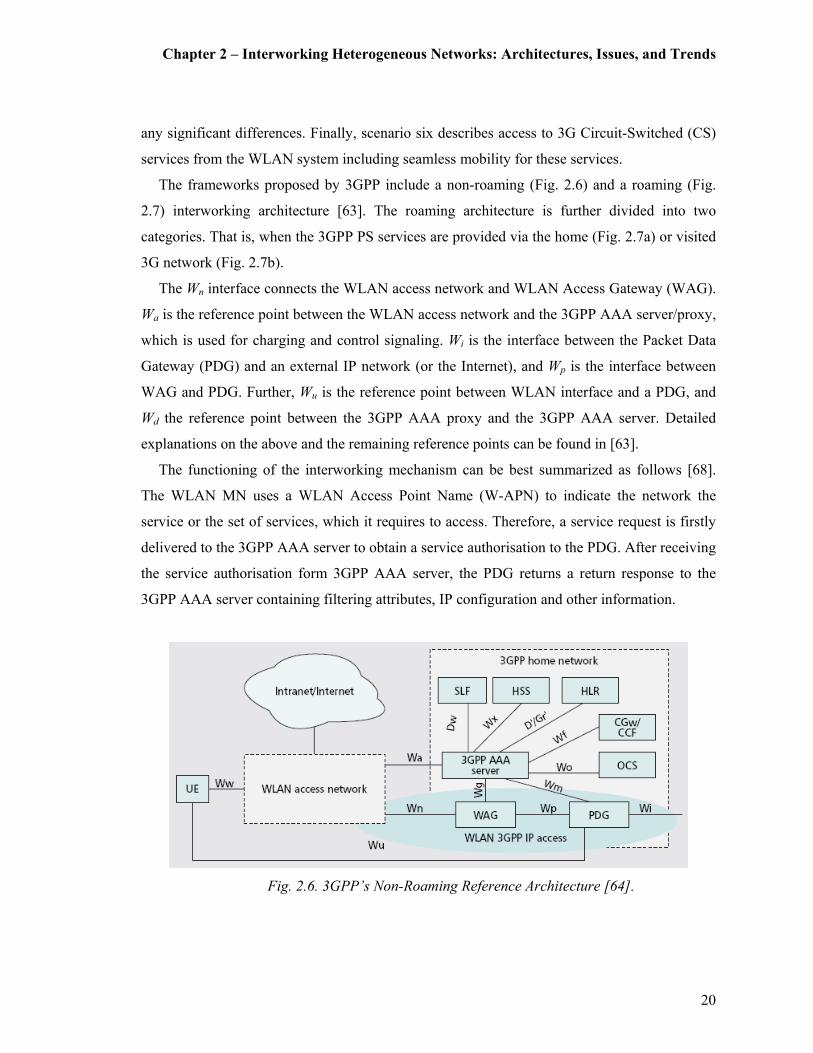
Chapter 2 – Interworking Heterogeneous Networks: Architectures, Issues, and Trends
20
any significant differences. Finally, scenario six describes access to 3G Circuit-Switched (CS)
services from the WLAN system including seamless mobility for these services.
The frameworks proposed by 3GPP include a non-roaming (Fig. 2.6) and a roaming (Fig.
2.7) interworking architecture [63]. The roaming architecture is further divided into two
categories. That is, when the 3GPP PS services are provided via the home (Fig. 2.7a) or visited
3G network (Fig. 2.7b).
The Wn interface connects the WLAN access network and WLAN Access Gateway (WAG).
Wa is the reference point between the WLAN access network and the 3GPP AAA server/proxy,
which is used for charging and control signaling. Wi is the interface between the Packet Data
Gateway (PDG) and an external IP network (or the Internet), and Wp is the interface between
WAG and PDG. Further, Wu is the reference point between WLAN interface and a PDG, and
Wd the reference point between the 3GPP AAA proxy and the 3GPP AAA server. Detailed
explanations on the above and the remaining reference points can be found in [63].
The functioning of the interworking mechanism can be best summarized as follows [68].
The WLAN MN uses a WLAN Access Point Name (W-APN) to indicate the network the
service or the set of services, which it requires to access. Therefore, a service request is firstly
delivered to the 3GPP AAA server to obtain a service authorisation to the PDG. After receiving
the service authorisation form 3GPP AAA server, the PDG returns a return response to the
3GPP AAA server containing filtering attributes, IP configuration and other information.
Fig. 2.6. 3GPP’s Non-Roaming Reference Architecture [64].

Chapter 2 – Interworking Heterogeneous Networks: Architectures, Issues, and Trends
21
Then the 3GPP AAA server responds to the WLAN Access Network with service
authorisation information, which is relayed to the WLAN UE (or MN). Finally, the WLAN UE
initiates a tunnel establishment request to the PDG. Once the tunnel is established between
PDG and the IP network, WLAN UE can access the service and user data can be routed
through the tunnel.
Fig. 2.7. 3GPP’s Roaming Reference Architecture: PS Based Services Provided via the
a) 3GPP Home Network and b) 3GPP Visiting Network [64].
2.6 3GPP2’s Approach to WLAN and Cellular Interworking
Similar to the previously mentioned case of 3GPP, 3GPP2 has also identified the benefits of
interworking the existing CDMA2000 network with the WLAN. The intention of 3GPP2–
WLAN interworking is to extend the 3GPP2 packet data services and/or capabilities to the
WLAN environment. The following briefly outlines the specifications for a proposal for
interworking between 3GPP2 systems and WLANs as specified by [69].
A logical interworking model depicting the interworking relationship scenarios is shown in
Fig. 2.8. The logical model in Fig. 2.8 shows the 3GPP2-WLAN interworking relationships
where the relationships are either direct or indirect (i.e. through a broker system). In the case of
a direct 3GPP2-WLAN interworking relationship, the interworking relationship is defined
between the 3GPP2 system and the WLAN system. In the case of an indirect 3GPP2-WLAN
interworking relationship, the interworking relationship is defined between a broker system and

Chapter 2 – Interworking Heterogeneous Networks: Architectures, Issues, and Trends
22
a WLAN system, and between a broker system and a 3GPP2 System. An interworking
relationship between a 3GPP2 system and a WLAN system can be considered as a many-to-
many relationship. As an extension to the above report [69], descriptions of requirements,
scenarios and networking architectures based on the IPv6 environment has been presented in
[70]. Furthermore, the authors have suggested specific cases or scenarios, which the
interworking model should carefully comply in order to comply with IPv6 mobility
management.
Although it is of lesser importance, there are other contributions made in this area of study.
For example, [71] proposes a solution for smart seamless handoff with QoS guarantee for
CDMA2000 and WLAN systems. According to this proposal, the MN conducts the QoS
negotiation with the new network during the handoff. Similar ideas with respect to end-to-end
QoS over CDMA2000 and WLANs have been expressed in [72]. Also, another proposal that
presents a Seamless Connection Control (SCC) scheme for interworking between CDMA2000
and WLAN systems by a method where the MN drives handover is available in [73].
Fig. 2.8. 3GPP2’s Proposed CDMA2000-WLAN Interworking Architecture [69].
MN
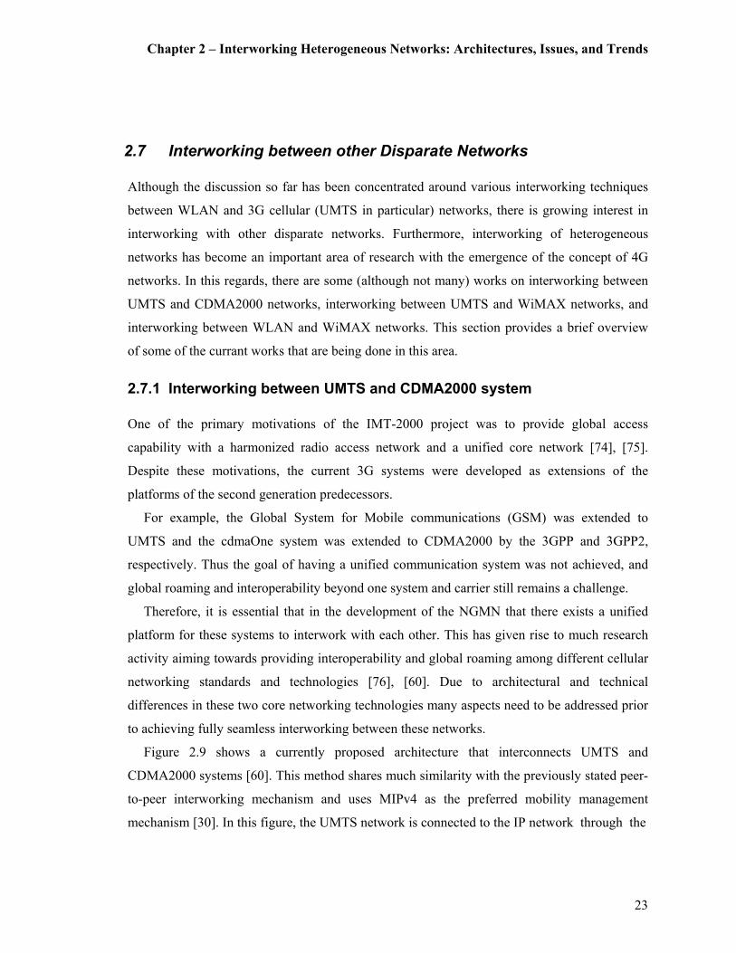
Chapter 2 – Interworking Heterogeneous Networks: Architectures, Issues, and Trends
23
2.7 Interworking between other Disparate Networks
Although the discussion so far has been concentrated around various interworking techniques
between WLAN and 3G cellular (UMTS in particular) networks, there is growing interest in
interworking with other disparate networks. Furthermore, interworking of heterogeneous
networks has become an important area of research with the emergence of the concept of 4G
networks. In this regards, there are some (although not many) works on interworking between
UMTS and CDMA2000 networks, interworking between UMTS and WiMAX networks, and
interworking between WLAN and WiMAX networks. This section provides a brief overview
of some of the currant works that are being done in this area.
2.7.1 Interworking between UMTS and CDMA2000 system
One of the primary motivations of the IMT-2000 project was to provide global access
capability with a harmonized radio access network and a unified core network [74], [75].
Despite these motivations, the current 3G systems were developed as extensions of the
platforms of the second generation predecessors.
For example, the Global System for Mobile communications (GSM) was extended to
UMTS and the cdmaOne system was extended to CDMA2000 by the 3GPP and 3GPP2,
respectively. Thus the goal of having a unified communication system was not achieved, and
global roaming and interoperability beyond one system and carrier still remains a challenge.
Therefore, it is essential that in the development of the NGMN that there exists a unified
platform for these systems to interwork with each other. This has given rise to much research
activity aiming towards providing interoperability and global roaming among different cellular
networking standards and technologies [76], [60]. Due to architectural and technical
differences in these two core networking technologies many aspects need to be addressed prior
to achieving fully seamless interworking between these networks.
Figure 2.9 shows a currently proposed architecture that interconnects UMTS and
CDMA2000 systems [60]. This method shares much similarity with the previously stated peer-
to-peer interworking mechanism and uses MIPv4 as the preferred mobility management
mechanism [30]. In this figure, the UMTS network is connected to the IP network through the

Chapter 2 – Interworking Heterogeneous Networks: Architectures, Issues, and Trends
24
Fig. 2.9.UMTS and CDMA2000 Interworking: MIPv4 based Approach.
GGSN that acts as the MIP FA. Following the GPRS attach and Packet Data Protocol (PDP)
context activation procedures, the MN performs the MIP registration to its HA via the GGSN
(i.e., MIP FA).
The HA maintains the MN’s location information (e.g., the GGSN, which is the MIP FA
address) and tunnels the IP datagrams to the MN. In the CDMA2000 network, the PDSN is the
MIP FA, which communicates with the HA through the IP network as previously described.
Both the UMTS and CDMA2000 networks connect to the IP multimedia network through the
MIP HA. That is when a terminal in the IP multimedia network originates a multimedia call to
the UMTS or CDMA2000 MN by using protocols such as H.323 [21] and SIP [22], and the
voice packets are first delivered to the MIP HA.
Then the MIP HA forwards these packets to the MN through the MIP FA (GGSN or the
Packet Data Serving Node (PDSN)). Despite the successful interworking framework used for
addressing IP mobility management, this architecture raises concerns such as service
continuation, seamlessness, and session mobility management. Thus this interworking
architecture cannot be successfully adopted in a heterogeneous networking environment such
as the future 4G network.
Another conceptually similar proposal to the above mentioned is illustrated in Fig. 2.10
[77], [78]. This proposed architecture, called Integrated InterSystem Architecture (IISA),
which adapts an integrated loose coupling model and implements MIPv6 [79] and Hierarchical
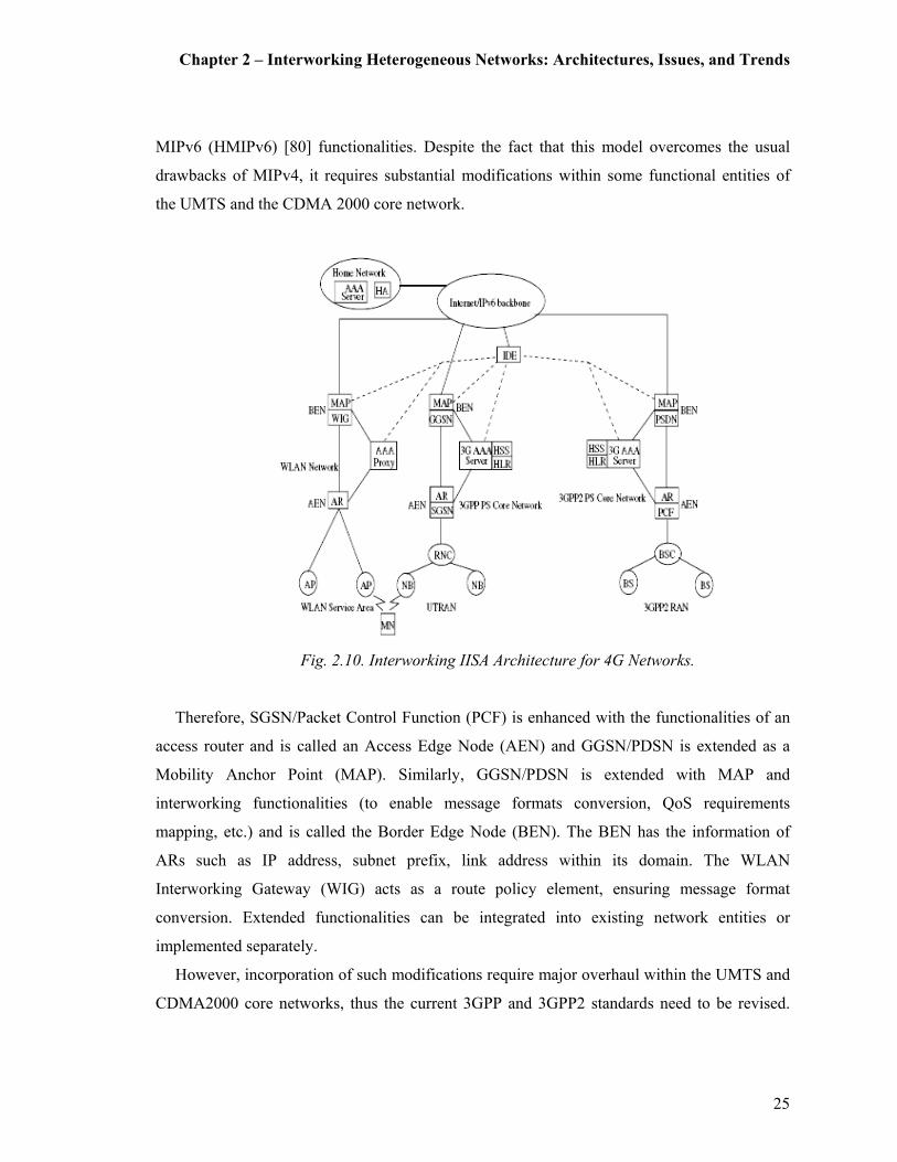
Chapter 2 – Interworking Heterogeneous Networks: Architectures, Issues, and Trends
25
MIPv6 (HMIPv6) [80] functionalities. Despite the fact that this model overcomes the usual
drawbacks of MIPv4, it requires substantial modifications within some functional entities of
the UMTS and the CDMA 2000 core network.
Fig. 2.10. Interworking IISA Architecture for 4G Networks.
Therefore, SGSN/Packet Control Function (PCF) is enhanced with the functionalities of an
access router and is called an Access Edge Node (AEN) and GGSN/PDSN is extended as a
Mobility Anchor Point (MAP). Similarly, GGSN/PDSN is extended with MAP and
interworking functionalities (to enable message formats conversion, QoS requirements
mapping, etc.) and is called the Border Edge Node (BEN). The BEN has the information of
ARs such as IP address, subnet prefix, link address within its domain. The WLAN
Interworking Gateway (WIG) acts as a route policy element, ensuring message format
conversion. Extended functionalities can be integrated into existing network entities or
implemented separately.
However, incorporation of such modifications require major overhaul within the UMTS and
CDMA2000 core networks, thus the current 3GPP and 3GPP2 standards need to be revised.
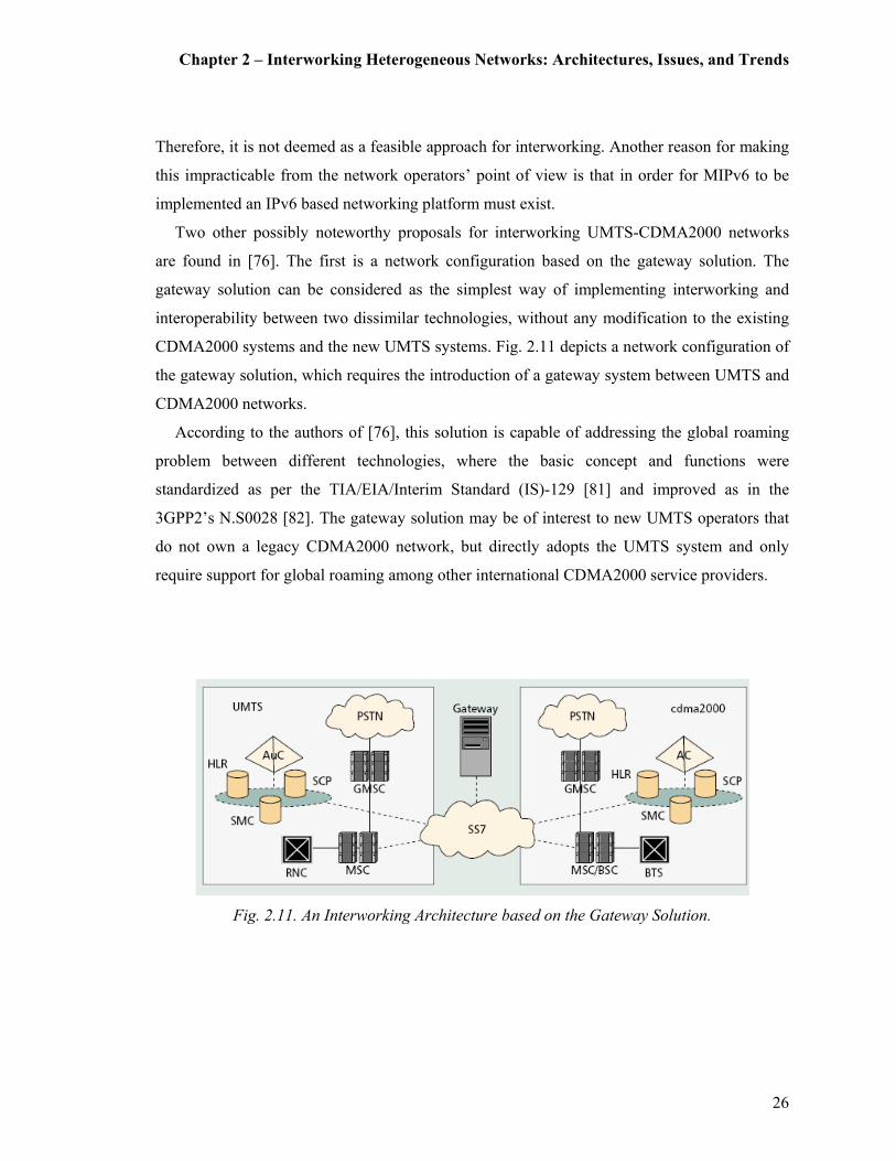
Chapter 2 – Interworking Heterogeneous Networks: Architectures, Issues, and Trends
26
Therefore, it is not deemed as a feasible approach for interworking. Another reason for making
this impracticable from the network operators’ point of view is that in order for MIPv6 to be
implemented an IPv6 based networking platform must exist.
Two other possibly noteworthy proposals for interworking UMTS-CDMA2000 networks
are found in [76]. The first is a network configuration based on the gateway solution. The
gateway solution can be considered as the simplest way of implementing interworking and
interoperability between two dissimilar technologies, without any modification to the existing
CDMA2000 systems and the new UMTS systems. Fig. 2.11 depicts a network configuration of
the gateway solution, which requires the introduction of a gateway system between UMTS and
CDMA2000 networks.
According to the authors of [76], this solution is capable of addressing the global roaming
problem between different technologies, where the basic concept and functions were
standardized as per the TIA/EIA/Interim Standard (IS)-129 [81] and improved as in the
3GPP2’s N.S0028 [82]. The gateway solution may be of interest to new UMTS operators that
do not own a legacy CDMA2000 network, but directly adopts the UMTS system and only
require support for global roaming among other international CDMA2000 service providers.
Fig. 2.11. An Interworking Architecture based on the Gateway Solution.
Chapter 2 – Interworking Heterogeneous Networks: Architectures, Issues, and Trends
27
The lack of total seamlessness for every function may not affect the global roaming market,
especially where roaming subscribers are accustomed to differences in the capabilities
supported by the home and visited networks. Another shortcoming of this solution is that the
subscriber database must be managed in three different places, which is not a technical problem
but requires another interface from the central database to the gateway system.
Secondly, Fig. 2.12 depicts a network configuration of a dual-stack solution, which requires
the Home Location Register (HLR), Service Control Point (SCP), and Short Message Centre
(SMC) to be modified and upgraded to support both protocol stacks required by the
CDMA2000 and UMTS technologies. A simple implementation of the two protocol stacks in
these systems is not sufficient to achieve integration of the two networks. Also, each protocol
stack performs and operates its own mobility management, call delivery, supplementary service
management functionalities.
However, coordination of mobility management, call delivery, and supplementary service
management between the two networks is kept through the dual-stack HLR, SCP, and SMC. In
summary, it can be said that the dual-stack solution best suits a network service provider that
wants to provide its customers both number portability and service transparency across its
CDMA2000 and UMTS systems. However, this solution does not sufficiently address the issue
of IP/terminal mobility or the session mobility for a potential user roaming between these two
networks.
Fig. 2.12. An Interworking Architecture based on the Dual-Stack Solution.
Chapter 2 – Interworking Heterogeneous Networks: Architectures, Issues, and Trends
28
2.7.2 Interworking between UMTS and WiMAX system
With the above motivations, similar attempts have also been made for interworking WiMAX
systems with 3G cellular technologies [83]. The initial works concentrated on different flavours
of the commonly known Loose and Tight Coupling architectures where a series of proposals
about different mobility management mechanisms have been presented in [84]. In the case of
interworking WiMAX with 3G cellular systems, MIP based approaches for mobility
management have been the most widely proposed [85]. Furthermore, despite its well known
drawbacks, MIP has become the popular choice for mobility management in mobile WiMAX
networks [57].
2.7.3 Interworking between WLAN and WiMAX system
Similar to the above two sections, there are also some notable contributions towards
interworking WLAN and WMAN systems in the current literature. A novel scheme for
achieving the above is given in [86], where a generic framework based on the IEEE 802.21
[87] has been proposed. Firstly this framework aims to provide continuity of service by
introducing a mechanism of QoS adaptation by which applications can adjust their QoS in
order to cope with the QoS provisioned in the visited network. Secondly, it points towards
making an intelligent handoff decision according to policies predefined in the system. Another
simple and straight forward proposal for interworking WLAN and WiMAX system is given in
[88], which also uses the IEEE 802.21 [87] standard as a coupling mediator.
Chapter 2 – Interworking Heterogeneous Networks: Architectures, Issues, and Trends
29
2.8 IEEE 802.21 Media Independent Handover Services
The current IEEE 802 standards do not support vertical handover between different types of
networks. They also do not provide triggers or other services (such as methods for selecting the
optimal network) to facilitate vertical handovers in a heterogeneous networking environment.
Therefore a new standard called IEEE 802.21 for supporting algorithms for enabling seamless
handover between different network types has been proposed for providing information to
allow handing over to and from cellular, GSM, GPRS, Wi-Fi, Bluetooth, IEEE 802.11, and
IEEE 802.16 networks through different handover mechanisms.. This standard is also called
the Media Independent Handover (MIH) or vertical handover function [89].
The objectives of the IEEE 802.21 standard can be summarized as [90], [91]:
� Enable roaming and seamless handover between heterogeneous wireless networks:
o To be available for use by multiple vendors and users,
o To be compatible with other IEEE 802 standards (e.g. WiMAX and WLAN),
� Include definitions for managed objects that are compatible with management standards
like the Simple Network Management Protocol (SNMP) [92],
� Include definition of a new link layer Service Access Point to provide a technology
independent common Link layer interface,
� Define a set of handoff enabling functions to coordinate with the upper layers (e.g., MIP
based mobility management at the Network Layer) to perform efficient vertical handoffs,
� Provide support for authentication, authorization, and network detection and selection
(although security algorithms and security protocols are defined in the standard).
When a session is handed off from one access point to another access point using the same
technology, the handover can usually be performed within that wireless technology itself
without involving the Media Independent Handover Function (MIHF) or the IP. For instance a
Voice over IP (VoIP) call from a Wireless Fidelity (Wi-Fi) handset to a Wi-Fi access point can
be handed over to another Wi-Fi access point within the same network. However if the
handover is from a Wi-Fi access point in a corporate network to a public Wi-Fi hotspot, then

Chapter 2 – Interworking Heterogeneous Networks: Architectures, Issues, and Trends
30
the MIH is required, since the two access points cannot communicate with each other at the
link layer, and are on different IP subnets [93].
The key functionalities provided by the MIH are communication among various wireless
layers, and between them and the IP layer. This handover procedure uses the information from
both MN and the network infrastructures. The IEEE 802.21 framework informs the available
network nearby to the MN and helps the MN to detect and select the network. This information
includes Link Layer information. The MIH may communicate with various IP protocols
including SIP for signaling, MIP for mobility management and DiffServ and IntServ for QoS.
The required messages are relayed by the MIHF that is located in the protocol stack
between the Layer 2 wireless technologies and IP at Layer 3 [89]. The MIHF provides
homogeneous interfaces independent from access technologies [94]. This interface handles
communications between the upper layer and lower layer as illustrated in Fig. 2.13.
Fig. 2.13. IEEE 802.21 Media Independent Handover Architecture.
Chapter 2 – Interworking Heterogeneous Networks: Architectures, Issues, and Trends
31
The MIHF provides three services as:
� Media Independent Event Service (MIES)
� Media Independent Command Service (MICS)
� Media Independent Information Service (MIIS)
The MIES supports the transfer, filtering, and classification of dynamic changes from Layer
2 to Layer 3. This delivers triggers on events such as link up, link down, and new link
available. The MICS offers the functions for managing and controlling Layer 2 from Layer 3.
If the MIH application wants handover and mobility, it can control the MAC layer by using
MICS. A set of standard commands for handover control would be switch link, configure link,
and initiate handover.
The MIIS offers information that is needed to perform the handover. It defines a service that
provides information for faster handovers such as a list of available networks, IP version, and
network operators. Using this information, the mobile terminal is able to make a decision on
the handover.
The transportation of the MICS, MIES, and MIIS messages over Layer 2 or Layer 3 is
facilitated via the MIHF transport protocol. IEEE 802.11u defines transport for IEEE 802.21
messages over IEEE 802.11. This is a proposed amendment to the IEEE 802.11-2007 standard
to add features that improve interworking with external networks [95].
As a current hot topic in research, many contributions have been made to the draft IEEE
802.21 standard [88],[86]. More specifically, there is growing interest towards investigating
how the emerging IEEE 802.21 standard could enable seamless, inter-technology handover
[96],[97].
One such proposal is for dynamically predicting and adjusting the buffer size to enhance the
functionality of the IEEE 802.21 [98]. The mechanism of the proposed scheme includes a
service specific layer, which decides the opportunity of handover and adjusts the buffer, which
stores the temporal streaming data for applications between handover.
There is also another proposal of a multi-interface scheme for the IEEE 802.21 MIH [93].
This proposal aims for having multi-interface mobile nodes to work with the standard
Transmission Control Protocol (TCP) and MIP protocols. Similarly, the problems and how to
efficiently use these multi-interfaced devices to achieve best data throughput, reduced packet
loss, and optimized handover is presented in [99].

Chapter 2 – Interworking Heterogeneous Networks: Architectures, Issues, and Trends
32
There are also other contributions on how the IEEE 802.21 standard may be applied to fast
moving vehicular networks [100]. In this, the authors’ have used the IEEE 802.21 MIH
services for optimizing the handover procedure in the Fast Handover for Mobile IPv6
(FMIPv6) protocol.
2.9 Open Issues and Research Themes
Despite the fact that there is a vast range (or flavors) of interworking architectures that have
recently been proposed, there exist many open issues. This section attempts to summarize some
of these issues, which may be considered as potential research themes under the current project
work.
The first of which is the issue of session mobility across WLAN and 3G cellular networks.
For instance, when a MN with an active IP-based session (File Transfer Protocol (FTP) [101]
or Hypertext Transfer Protocol (HTTP) [102], say) moves from a WLAN to a 3G cellular
network (or vice-versa), the session must be seamlessly handed over from one network to
another. Possible research questions that may arise from such a situation are: how to detect the
entering and leaving from a hotspot; which part of the network to handoff; and which
mechanisms to perform authenticated handoff. Thus, how to provide/enable seamless
continuity of service across WLAN and 3G cellular networks can be ranked as a top issue.
Naturally, the solution/s to the above would depend on the type of integration architecture
used. For instance, mobility management for a tight coupling architecture can be seen as a
moderately complex issue since 3G mobility management schemes could be directly applied
[1]. However, this becomes an extremely complex and a rather challenging issue for a loosely
coupled architecture. It requires emulators for 3G signaling, possible protocol stack
modifications, and multiple mobility management schemes [3]. Such mobility management
schemes may comprise of 3G cellular and IEEE 802.11 mobility management schemes, IP and
SIP registration schemes, and Domain Name System (DNS) [103] update schemes.
Lastly, the peer-to-peer interworking architecture, where each network behaves
independently, is considered to be the least complex. The most commonly used mobility
management scheme under this approach is the MIP approach [3]. However, other schemes
may apply depending on the type and the level of integration. A similar concern, which is very
Chapter 2 – Interworking Heterogeneous Networks: Architectures, Issues, and Trends
33
much related to the above is the problem of IP address allocation and distribution for a MN in a
WLAN-3G heterogeneous networking environment.
Another important issue is to define a mechanism for user data routing via heterogeneous
networks. How an optimal routing path can be decided is still an open issue, which is currently
being investigated by the 3GPP. Matching the QoS requirements and service provisioning
between WLAN and the 3G cellular networks can also be pointed out as another related issue.
Provisioning of unified/integrated mechanisms for AAA and security in general is another
high priority concern. Among the related work done by the 3GPP in this area, one such
recommendation is to eventually adopt the IEEE 802.11i standard [TS 33.234]. Although not
much, [50] and [104] are some works that deals with this security aspect in regards to
interworking heterogeneous networks. A mechanism for location aware authentication for
interworked 3G-WLAN systems is proposed in [50] and a handover architecture for seamless
mobility and an extended authentication mechanism is proposed in [104].
Another related question is: whether AAA is managed at the WLAN, 3G core network or
independently? Furthermore, charging options such as post-paid, pre-paid charging and IP-flow
based charging must also be considered. Last but not least, terminal capabilities such as support
of high data rate applications, screen size, computational power, and network selection
mechanisms must also be addressed.
Out of the above mentioned research challenges, this thesis aims towards proposing a
mobility-aware novel architecture for interworking heterogeneous mobile data networks. This
is expected to facilitate real-time session management including session establishment and
seamless session handoff across dissipate networks. Further, by considering the complications
of the existing network coupling mechanisms, a universal coupling mediator for real-time
session negotiation and management is proposed. This mechanism is further capable of
resolving the issue of IP mobility with mechanisms in place for the issue of IP address
allocation and distribution in such environments. Finally, although it is out of the scope of this
thesis, the proposed framework has adequate provisioning to comply with the current IEEE
802.11i AAA standards as outlined in the future works section.
Chapter 2 – Interworking Heterogeneous Networks: Architectures, Issues, and Trends
34
2.10 IMS: IP Multimedia Subsystem
As stated above, the aim of this thesis is to propose an interworking model, which is capable of
providing a MN the highest possible level of access over different heterogeneous networks,
where fully seamless access is considered to be the optimal accomplishment. A novel approach
for solving this problem is to explore the possibility of introducing one single centralized entity
for handling mobility management between different networks.
The quest for such a centralized mobility management entity came across a somewhat
similar idea expressed in [105] and [106]. According to [105], it was possible to use the
3GPP’s IMS [31] for supporting real-time session negotiation and management between
heterogeneous networks. This was a positive direction since this could be the ideal candidate
for session mobility management. However, apart from the concept of having the IMS as a
session manager and a service delivery framework [107] and [108] do not address any issues
pertaining to mobility management.
Furthermore, complementing to the ideas expressed in [105], there is also another paper
expressing how the SIP protocol (i.e., the main signaling protocol used in the IMS), is capable
of handling session management in a UMTS-WLAN networking environment [109]. However,
the issue of mobility management was not addressed in this case either. Therefore, [105], [109]
can be seen as the main inspirations to our works.
A similar idea of using the IMS as a coupling medium (only for session mobility
management) has also been recently published at a much later stage in [110], it mainly focuses
on the QoS guarantee and AAA aspects provided by the IMS. Most importantly the
architecture fails to sufficiently describe a mechanism for seamless vertical handoff and
mobility management. Additionally there are also similar works carried out in relation to using
the 3GPP2 IMS [111] as a mediator for coupling in the process of interworking CDMA2000
networks with a WLANs as per the Telecommunications Industry Standard (TIA) report [112].
This thesis proposes a solution capable of overcoming the above limitations by adopting a
unified coupling framework for interworking between heterogeneous networks [35]. This
framework provides a MN the highest possible level of internetworking, with fully seamless
continuity of service (mobility) across heterogeneous networks. As an arbitrator for

Chapter 2 – Interworking Heterogeneous Networks: Architectures, Issues, and Trends
35
internetworking between the WLAN and the WiMAX systems with the 3G Cellular network
(either UMTS or CDMA2000), the IMS is deployed.
A clear advantage of using the IMS is its ability for real-time session negotiation and
management using the SIP [113]. Nevertheless, MIP also plays an important role in the IP
(terminal) mobility management in the proposed approach. In order to set the ground for
introducing our proposed interworking mechanisms the next sections provide a comprehensive
overview of the 3GPP and 3GPP2’s IMS architectures.
2.10.1 3GPP IMS Architecture
In UMTS, prior to Release 4, IP connectivity was a service provided by the core network [114].
However, this was only limited for standardization of basic services such as initiation,
modification, and termination of multimedia sessions. Even when the wireless provider offered
(non-standard) enhanced IP services, end-to-end service provisioning across network
boundaries was infeasible. Hence, subscribers had to use a variety of third-party applications
and use third-party providers of IP multimedia services [115].
Fig. 2.14. The IP Multimedia Subsystem (IMS) Architecture.
Chapter 2 – Interworking Heterogeneous Networks: Architectures, Issues, and Trends
36
The 3GPP’s UMTS Release 5 [116] and 6 [117] introduced the IMS to the UMTS core
network to overcome the above drawbacks [31]. The IMS comprised the required
characteristics for controlling of multimedia sessions, and thus essential for the provisioning of
IP multimedia services in UMTS. It also provides for an entry point for third-party multimedia
applications and services in a controlled and secure manner. In order to facilitate these services,
the IMS is featured with a number of key mechanisms such as session negotiation and
management, QoS, mobility management and provisioning for AAA.
Figure 2.14 provides a general overview of the IMS architecture, outlining the essential
network elements used for providing real-time IP multimedia services [31]. Since the IMS
architecture specifically relies on the packet-switching domain for transport and local mobility
management, the IMS operates independently to the circuit-switched domain. Thus circuit-
switching elements such as mobile switching centers have been excluded from Fig. 2.14.
2.10.1.1 Call Session Control Functions
The Call State Control Functions (CSCF) and the Home Subscriber Server (HSS) are the key
elements of the IMS, which play a vital role in call/session control. By and large, the role of a
CSCF can be seen analogous to the SIP Server in the IETF architecture [118]. They are
essentially involved in processing signaling messages for controlling multimedia/call sessions
for users. Apart from this, the CSCFs are also involved in the address translation, performing
service switching and vocoder negotiation, and handling of the subscriber profile. Depending
on various configurations and scenarios, the roles for the CSCFs are categorized as Proxy
CSCF, Interrogating CSCF, and Serving CSCF.
2.10.1.2 Proxy CSCF
The Proxy-CSCF (P-CSCF) is the first contact point of the IMS, which is located in the same
network as the GGSN. This could either be in the home network or the visiting network. The
P-CSCF has two main functions. Its primary function is to be the QoS policy enforcement
point within the IMS. Its secondary responsibility is to provide the local control for emergency
services. It also provides the local numbering plans directory assistance. The P-CSCF forwards
Chapter 2 – Interworking Heterogeneous Networks: Architectures, Issues, and Trends
37
the SIP registration messages and session establishment messages to the home network of the
user. The P-CSCF can be seen as equivalent to a proxy server in an IMS architecture.
2.10.1.3 Interrogating CSCF
The I-CSCF is the “main entrance” to the home network from a visited network. With the
assistance of the HSS, the I-CSCF selects the appropriate Serving-CSCF (S-CSCF). This is an
optional node in the IMS architecture as the P-CSCF may also be configured to contact the S-
CSCF directly. Nevertheless, the I-CSCF has a number of functionalities. It performs load
balancing between S-CSCFs with the support of the HSS. The I-CSCF can hide the home
network form other network operators by providing a single point of entry into the network. It
is also capable of performing some forms of billing. Lastly, since the I-CSCF acts as the
gateway into the home network, it also supports the firewall function.
2.10.1.4 Serving CSCF
The S-CSCF is the node that eventually performs the actual user registration and session
control for the IMS network. The S-CSCF may also be capable of provisioning a set of
specialized services. There can be several S-CSCFs in the network. They can be added as
needed based on the capabilities of the nodes or the capacity requirements of the network. One
key advantage of this architecture is that the home network provides the service features to the
MN. Thus the capabilities of the visited network do not restrict the functionality of the MN.
2.10.1.5 Home Subscriber Server
The HLR has evolved into the Home Subscriber Server (HSS). Interfacing with the I-CSCF
and the S-CSCF, the HSS can be regarded as a master database, which acts as a repository for
subscription and location information. Since multiple HSS functions may be available in a
network, the subscription location function is queried by CSCFs during registration or session

Chapter 2 – Interworking Heterogeneous Networks: Architectures, Issues, and Trends
38
initiation. The HSS uses a non IETF based protocol, the Cx interface, which is an IP based
protocol [119].
2.10.1.6 Media Gateway Control Function and Media Gateway
In an all-IP environment, there would be no need for anything other than the CSCFs and the
HSS. However, this is not the case in reality. Hence the IMS must have facility to interwork
with the legacy Public Switched Telephony Network (PSTN) and mobile networks. Therefore,
the Media Gateway Control Function (MGCF) interconnects with circuit switched networks
via the corresponding IMS Media Gateway (IMS-MGW). This feature supports for scenarios
where sessions are established between the packet switching domain and the PSTN. The media
translation from signals encoded in one format to another is performed by the IMS-MGW.
Also there is the Media Resource Function Controller (MRFC), which performs processing of
media streams through the corresponding Media Resource Function Processor (MRFP).
Further discussion on the IMS-MGW and MGCF are not included since it is beyond the scope
of this section.
2.10.1.7 IMS Related Protocols
The protocols which have been defined within the IMS architecture can be classified under
thee broad categories. The first category, which is also the most important, comprises of the
protocols used in the signaling and session control plane. The second and third categories
consist of protocols used in the media plane and protocols used for authentication and
authorisation.
2.10.1.8 The Session Control Protocol: SIP
The SIP is the core protocol chosen by the 3GPP to perform signaling and session management
within the IMS [118]. It is essentially a standard application layer protocol designed to
facilitate call information to be carried across network boundaries and control the attributes of

Chapter 2 – Interworking Heterogeneous Networks: Architectures, Issues, and Trends
39
end-to-end sessions in IP based networks. Therefore, SIP is not a vertically integrated
communication protocol. It is rather a component that needs to be used with other IETF
protocols to build a complete multimedia architecture.
The capabilities of SIP can be listed as:
� Determine the location of the target end point: SIP supports address resolution, name
mapping, and call redirection,
� Determine the media capabilities of the target end point: SIP determines the lowest level of
common services between end points using the Session Description Protocol (SDP),
� Determine the availability of the target endpoint: If the call cannot be completed, SIP
determines why the target end point was unavailable,
� Establish a session between the originating and target end point: If the end point is located,
SIP establishes a session. It also supports mid-call changes, and
� Handle transfer and termination of calls: SIP supports the transfer of calls form one end
point to another.
It is also an extensible protocol, which enabled the IETF to introduce new methods, define
new headers and easily integrate in to the core protocol. This extensible nature of the protocol
was used for incorporating additional features to suit the needs of the 3GPP’s proposed IMS
architecture. These new 3GPP SIP extensions can be broadly classified as general, session
operation, QoS, AAA, and security. A detailed description and a comparison of the IETF SIP
versus the 3GPP SIP is available from [105].
2.10.1.9 Other Protocols
As previously mentioned, the remaining protocols used within the IMS architecture can be
broadly categorized as protocols used in the media plane and the AAA protocols. The IMS uses
the Real Time Protocol (RTP) for transporting real time audio and video over the User
Datagram Protocol (UDP) as the transport protocol [120]. It further uses the Real Time Control
Protocol (RTCP) for providing the RTP with QoS statistics and information to provide inter-
media synchronization on the media stream [120]. Lastly, the authentication protocol used by
the IMS is DIAMETER [121]. Further details on the above protocols (RTP, RTCP and
DIAMETER) are not included as it is beyond the scope of this thesis.
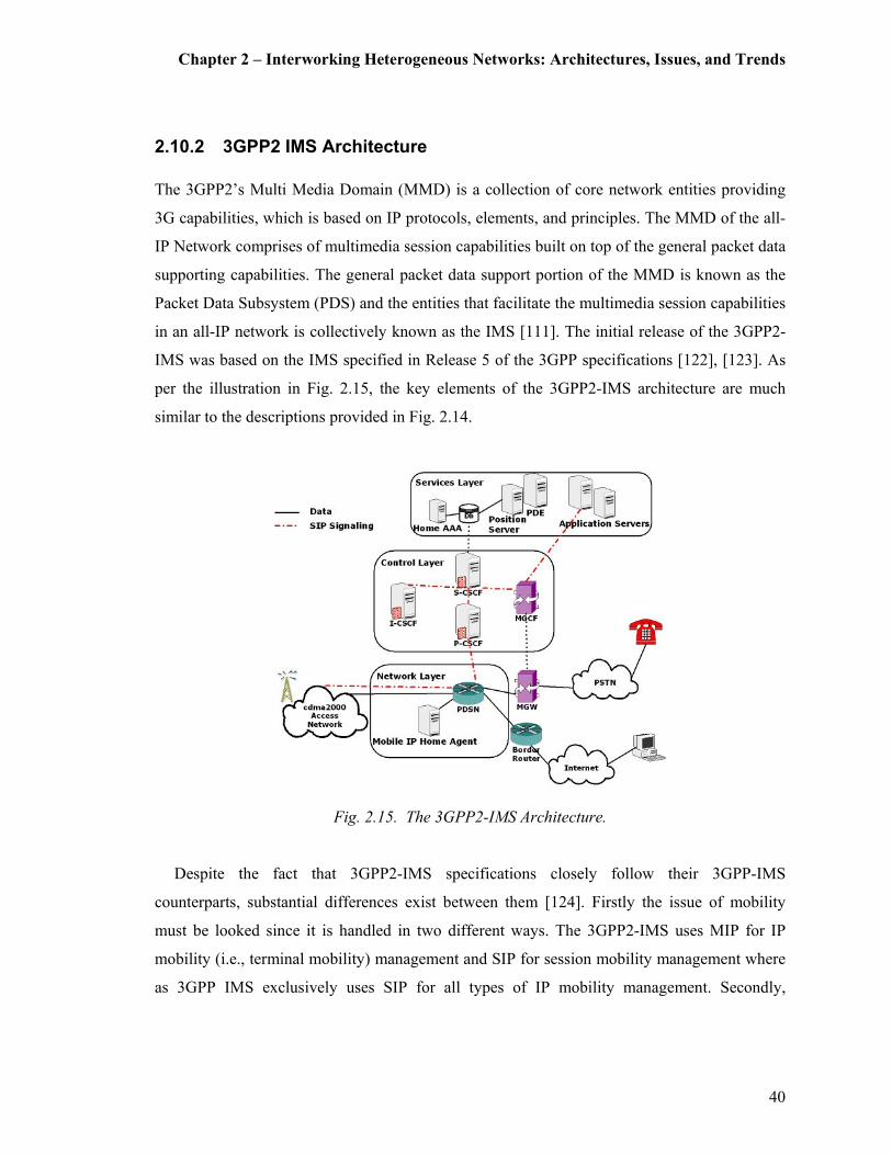
Chapter 2 – Interworking Heterogeneous Networks: Architectures, Issues, and Trends
40
2.10.2 3GPP2 IMS Architecture
The 3GPP2’s Multi Media Domain (MMD) is a collection of core network entities providing
3G capabilities, which is based on IP protocols, elements, and principles. The MMD of the all-
IP Network comprises of multimedia session capabilities built on top of the general packet data
supporting capabilities. The general packet data support portion of the MMD is known as the
Packet Data Subsystem (PDS) and the entities that facilitate the multimedia session capabilities
in an all-IP network is collectively known as the IMS [111]. The initial release of the 3GPP2-
IMS was based on the IMS specified in Release 5 of the 3GPP specifications [122], [123]. As
per the illustration in Fig. 2.15, the key elements of the 3GPP2-IMS architecture are much
similar to the descriptions provided in Fig. 2.14.
Fig. 2.15. The 3GPP2-IMS Architecture.
Despite the fact that 3GPP2-IMS specifications closely follow their 3GPP-IMS
counterparts, substantial differences exist between them [124]. Firstly the issue of mobility
must be looked since it is handled in two different ways. The 3GPP2-IMS uses MIP for IP
mobility (i.e., terminal mobility) management and SIP for session mobility management where
as 3GPP IMS exclusively uses SIP for all types of IP mobility management. Secondly,

Chapter 2 – Interworking Heterogeneous Networks: Architectures, Issues, and Trends
41
attention can be drawn to the use of IPv4 vs. IPv6. Although 3GPP mandates the IMS over
IPv6, the 3GPP2 IMS specification does not make such distinction.
As a common interworking platform for mobility management in NGMN is considered,
resolving the interaction of 3GPP-IMS with MIP becomes a new challenge. Therefore, the
framework proposed in this thesis uses MIP for providing terminal mobility and limits SIP for
session mobility management in a generalized IMS architecture.
As previously mentioned, although 3GPP mandates IMS over IPv6, 3GPP2 does not make
such a specification. Therefore, for 3GPP2, either MIPv4 [125] over IPv4 or MIPv6 [126] over
IPv6 can be used, which also gives more freedom for network operators. As per the
specifications of 3GPP2, if MIPv4 is deployed, the PDSN of the home network may act as the
MIP HA. As the MN moves form one PDSN to another, the new PDSN may act as the MIP
FA, which becomes the new point of contact for the MN.
Therefore when the MN is attached to a different PDSN the HA becomes an anchor point
for the MN’s traffic flow, particularly when reverse tunneling and triangular routing are taking
place. In the event when MIPv6 is being implemented, a direct peer-to-peer communication
can be established through its route optimization operation [126]. Since 3GPP2’s standard for
CDMA2000 does not fully support inter-PDSN mobility for IPv6, the proposed design will
primarily be based on MIPv4 [127]. As a result the route optimization option will not be
available in its current form. However, transition of this model to MIPv6 can be easily done by
addressing user authentication, address allocation and enabling the MN to perform the MIPv6
update procedures [128].
Although it is of lesser importance, other differences between 3GPP and 3GPP2 IMS can
be briefly stated as:
� 3GPP2’s Home AAA and its database being equivalent to 3GPP’s HSS. 3GPP2-IMS is not
using PDP context activation for P-CSCF discovery,
� Unlike in 3GPP, the P-CSCF and PDSN do not need to reside in the same network,
� 3GPP2-IMS defines a new position server and a position determining entity for providing
positioning information, and
� The other differences are codecs, QoS procedures, S-CSCF/P-CSCF/HSS interfaces,
authentication procedures to name a few.
Chapter 2 – Interworking Heterogeneous Networks: Architectures, Issues, and Trends
42
Detailed discussions on the above are not provided as these issues are beyond the scope of this
thesis.
2.11 Summary and Conclusions
The purpose of this Chapter was to provide an in-depth discussion on the current architectures,
research issues, and future trends on interworking heterogeneous mobile data networks in a
NGMN. The discussion was initiated by introducing the current and the most notable
interworking architectures and related design issues. Amongst the discussed interworking
architectures were the three coupling methods (i.e., Tight Coupling, Loose Coupling, and Pee-
to-Peer Networking), 3GPP’s proposed approach for interworking, 3GPP2’s proposed
approach for interworking, the IEEE’s proposed approach for interworking (i.e., IEEE 802.21
MIH), and other approaches adopted for interworking dissimilar networks such as different 3G
cellular networking technologies and BWA networks. This Chapter also discussed the open
issues and research trends in interworking and introduced the IMS as a potential candidate for a
coupling media for interworking dissimilar networks. Finally the Chapter concludes by
explaining the 3GPP’s and 3GPP2’s IMS architectures, which facilitates the necessary
groundwork for the introduction of a novel interworking framework in the next Chapter.
Chapter 3 – A Basic Framework for Interworking WLAN and UMTS Networks
43
V{tÑàxÜ F A Basic Framework for Interworking WLAN
and UMTS Networks
This Chapter proposes a novel architecture for interworking WLAN-UMTS by using the IMS
as a unified coupling media for real-time session negotiation and management. As a result,
mobile users will be able to use WLANs as a complementary technology for 3G cellular data
networks, thus experience ubiquitous data services and very high data rates across
heterogeneous networks while providing the end user with a seamless experience. The
remainder of the Chapter is organized as follows: Firstly the introduction section reiterates the
motivations for this work and the importance of an interworking framework for heterogeneous
networks. The next section describes the proposed architectural framework followed by a
discussion on various interworking scenarios of the design. Subsequently OPNET based
simulation model is introduced for validation. Finally the section on analytical modeling and
performance evaluations are presented. The contents provided under this Chapter have
contributed to the following publications: The interworking architecture and the OPNET
simulation platform presented in this Chapter has contributed to [35], the basic analytical
model has contributed to [36] and [37], the extended analysis using the Queuing Theory has
contributed to [38], and lastly the signaling cost analysis method has contributed to [39].
3.1 Introduction
As modern high-speed data applications tend to impose a challenge on the bandwidth
limitations of existing 3G cellular networks, a strong urge for the development of efficient
mechanisms for interworking these with WLAN technologies have been raised. In the event of
successful interworking of theses two technologies, mobile users will be able to experience
ubiquitous data services and very high data rates across heterogeneous networks by using

Chapter 3 – A Basic Framework for Interworking WLAN and UMTS Networks
44
WLANs as a complementary technology for next generation cellular data networks, while
providing the end user with a seamless experience [25]. This will enable a user to access 3G
cellular services via a WLAN, while roaming within the range of a hotspot.
With the aim for addressing this need, a variety of internetworking architectures for 3G
Cellular and WLANs have been proposed [31]. By and large, these internetworking
architectures may be categorized as tight coupling, loose coupling, and peer-to-peer networking
(also referred as no-coupling) [26], [27]. However, these approaches seem to provide limited
internetworking capability as none of these designs have successfully addressed the issue of
seamless continuation of services. A detailed and comprehensive discussion on the current
research activities and trends in relation to interworking of dissimilar networks was presented
in the previous Chapter.
Having realized the importance of such an interworking mechanism, our work was
motivated towards developing a solution that is capable of achieving the highest possible level
of service continuation during the vertical handoff of sessions between such heterogeneous
networks. Therefore, this Chapter presents the proposed architecture for WLAN-UMTS
interworking, which is capable of meeting these challenges as initially published in [33] and
[34]. The novelty of this proposed solution for WLAN-UMTS interworking is that it uses the
3GPP’s IMS as an arbitrator for real-time session negotiation and management.
3.2 Architectural Framework
The recommended framework for internetworking is illustrated in Fig. 3.1. The flow of data
originates from the source MN, through the SGSN and the GGSN of the visiting UMTS
network, and reaches the destination network. This model uses the Visitor-GGSN approach to
avoid the inter-PLMN backbone and to make data routing simpler for the network operator
[129]. In whichever the approach, the data flow bypasses the IMS network. Thus the IMS is
said to follow the philosophy of having different paths for user data and signaling through the
network.
The SIP signaling messages originate from the MN via the UMTS Terrestrial Radio Access
Network (UTRAN), through the SGSN and GGSN, out to the CSCFs and finally to the
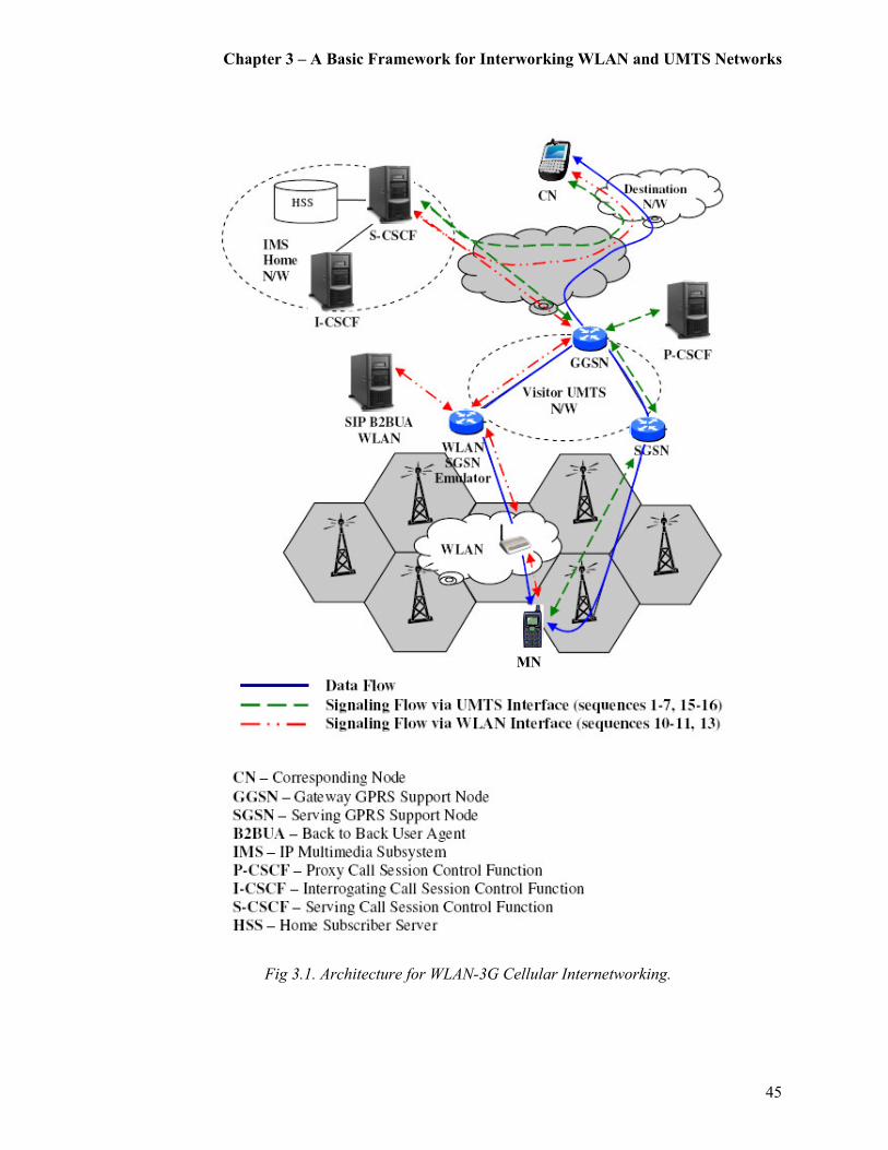
Chapter 3 – A Basic Framework for Interworking WLAN and UMTS Networks
45
Fig 3.1. Architecture for WLAN-3G Cellular Internetworking.
MN

Chapter 3 – A Basic Framework for Interworking WLAN and UMTS Networks
46
destination network. It is important to note that when the MN requires establishing a session,
this request is always sent to the (Home) S-CSCF via the (Visiting) P-CSCF. During the
exchange of the SIP signaling, both the SGSN and the GGSN act as routers by merely
forwarding SIP messages. The data originating from the WLAN gets routed via the SGSN
emulator through the GGSN. Hence, it essentially emulates the WLAN as another SGSN
belonging to the same UMTS network. Thus mobility can be managed by the UMTS network.
Some of the functionalities of the BSS are bypassed in this approach and the load on the
UMTS network, created by the high volume of the WLAN data traffic, may also be sufficiently
reduced. Furthermore, the MN does not require any change of IP addressing between the
WLAN and the UMTS network as long as the two networks are connected via the same
GGSN.
3.2.1 Session Establishment
The establishment of a SIP session within an UMTS IMS environment is involved with several
functions. The key steps required for obtaining access to SIP services can be outlined as
follows. The first step involves with the MN powering on and locking to the UMTS network. It
is assumed that this step is already performed by the MN, and will not be discussed in detail.
Once the above mentioned system acquisition is done, the next step is to establish a data
connection, or set up a data pipeline, for the SIP and other services. In order to perform the SIP
session establishment the MN is initially unaware of the IP address of the P-CSCF. Thus the
data connection must be completed in two-steps by using the Attach [130] and PDP context
activation [131] message sequences. The activation of a PDP context assigns an IP address for
the MN. With the activation of the PDP context the MN is able to identify the P-CSCF for the
registration with the UMTS SIP network.
Prior to establishing a SIP session, the MN requires performing a service registration
function to let the IMS know of its location. The MN acts as a SIP client and sends a SIP
registration message to its home system through the P-CSCF. The basic steps for a SIP service
registration can be summarized as follows. Firstly, the HSS for the MN is notified of its current
location for the HSS to update the subscriber profile accordingly. Next the HSS checks if the
MN is allowed to register in the network based on the subscriber profile and operator

Chapter 3 – A Basic Framework for Interworking WLAN and UMTS Networks
47
limitations, and grants authorization. Once authorized, a suitable S-CSCF for the MN is
assigned and its subscriber profile is sent to the designated S-CSCF.
Fig. 3.2. IMS-SIP Based Session Handoff.
After the activation of the PDP context and the service registration, the MN is ready to
establish a media/data/call session. As illustrated in Fig. 3.2, the sequence of the SIP session
origination procedures can be described as follows. The mobile origination procedure is
initiated by a SIP INVITE message sent form the UMTS interface of the source MN (step 1).
Chapter 3 – A Basic Framework for Interworking WLAN and UMTS Networks
48
This initial message is forwarded from the P-CSCF to the S-CSCF of the originating network,
via the CSCFs of the terminating network, and finally to the Corresponding Node of the
destination. This SIP INVITE request carries a Session Description Protocol (SDP) [132] body
indicating the IP address and port numbers where the source wants to receive the media
streams. Furthermore, the INVITE also contains a request to follow the precondition call flow
model. This is important because some clients require certain preconditions (that is, QoS
levels) to be met before establishing a session. The requirement for using the preconditions call
flow model in IMS is mainly because in cellular networks radio resources for the media plane
are not always available. If the preconditions extension was not used, when the called party
accepts the call, the source and destination may not be ready and consequently the first few
packets may be lost.
Next, this model requires that the destination responds with a 183 Session Progress
containing a SDP answer (step 2). The SDP answer contains the media streams and codecs that
the destination is able to accept for this session [132]. The acknowledgement for the reception
of this provisional response by a Provisional Response ACKnowledgement (PRACK) [133]
request follows afterwards (step 3). If the destination does not receive a PRACK response
within a determined time, it will transmit the provisional response. When the PRACK request
successfully reaches the destination a 200 OK response is generated by the destination with an
SDP answer (step 4). Next an UPDATE request [134] is sent by the source containing another
SDP offer, in which the source indicates that the resources are reserved at his local segment
(step 5). Once the destination receives the UPDATE request, it generates a 200 OK response
(step 6). Once this is done, the MN can start the media/data flow and the session will be in
progress (via the UMTS interface).
3.2.2 Session Handoff: UMTS to WLAN
When the MN, which is currently connected to the UMTS network, detects the presence of a
WLAN around its vicinity, vertical handoff procedures may be initiated. This can specifically
be seen as a make-before-break instance of vertical handoff where there exists an overlapping
coverage. As per the illustration in of the overlapping coverage scenario in Fig. 3.3, the WLAN
signal strength is first observed over time t0 to t1 (say). As the intensity of the WLAN signal
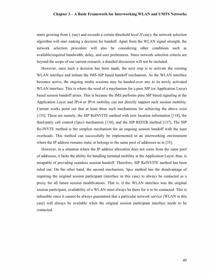
Chapter 3 – A Basic Framework for Interworking WLAN and UMTS Networks
49
starts growing from L (say) and exceeds a certain threshold level H (say), the network selection
algorithm will start making a decision for handoff. Apart from the WLAN signal strength, the
network selection procedure will also be considering other conditions such as
available/required bandwidth, delay, and user preferences. Since network selection criteria are
beyond the scope of our current research, a detailed discussion will not be included.
However, once such a decision has been made, the next step is to activate the existing
WLAN interface and initiate the IMS-SIP based handoff mechanism. As the WLAN interface
becomes active, the ongoing media sessions may be handed-over any to its newly activated
WLAN interface. This is where the need of a mechanism for a pure SIP (or Application Layer)
based session handoff arises. This is because the IMS performs pure SIP based signaling at the
Application Layer and IPv4 or IPv6 mobility can not directly support such session mobility.
Current works point out that at least three such mechanisms for achieving the above exist
[135]. These are namely; the SIP ReINVITE method with new location information [118], the
third-party call control (3pcc) mechanism [136], and the SIP REFER method [137]. The SIP
Re-INVTE method is the simplest mechanism for an ongoing session handoff with the least
overheads. This method can successfully be implemented in an interworking environment
where the IP address remains static or belongs to the same pool of addresses as in [35].
However, in a situation where the IP address allocation does not come from the same pool
of addresses, it lacks the ability for handling terminal mobility at the Application Layer, thus, is
incapable of providing seamless session handoff. Therefore, SIP ReINVITE method has been
ruled out. On the other hand, the second mechanism, 3pcc method has the disadvantage of
requiring the original session participant (interface in this case) to always be contacted as a
proxy for all future session modifications. That is, if the WLAN interface was the original
session participant, availability of a WLAN must always be there for it to be contacted. This is
infeasible since it cannot be always guaranteed that a particular network service (WLAN in this
case) will always be available when the original session participant interface needs to be
contacted.
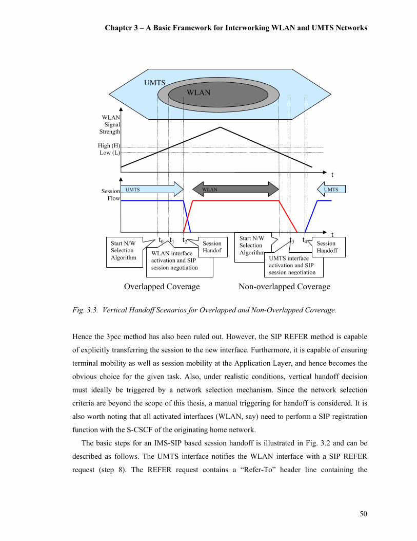
Chapter 3 – A Basic Framework for Interworking WLAN and UMTS Networks
50
Fig. 3.3. Vertical Handoff Scenarios for Overlapped and Non-Overlapped Coverage.
Hence the 3pcc method has also been ruled out. However, the SIP REFER method is capable
of explicitly transferring the session to the new interface. Furthermore, it is capable of ensuring
terminal mobility as well as session mobility at the Application Layer, and hence becomes the
obvious choice for the given task. Also, under realistic conditions, vertical handoff decision
must ideally be triggered by a network selection mechanism. Since the network selection
criteria are beyond the scope of this thesis, a manual triggering for handoff is considered. It is
also worth noting that all activated interfaces (WLAN, say) need to perform a SIP registration
function with the S-CSCF of the originating home network.
The basic steps for an IMS-SIP based session handoff is illustrated in Fig. 3.2 and can be
described as follows. The UMTS interface notifies the WLAN interface with a SIP REFER
request (step 8). The REFER request contains a “Refer-To” header line containing the
UMTS
WLAN
Signal
Strength
High (H)
Low (L)
Non-overlapped Coverage Overlapped Coverage
t0 t1 t2 t3 t4 t5
Session
Flow
WLAN
t
t
WLAN UMTS UMTS
Start N/W
Selection
Algorithm WLAN interface
activation and SIP
session negotiation
Session
Handof
f
Start N/W
Selection
Algorithm UMTS interface
activation and SIP
session negotiation
Session
Handoff
Chapter 3 – A Basic Framework for Interworking WLAN and UMTS Networks
51
destination SIP Uniform Resource Identifier (URI) and a “Replaces” header line identifying the
existing session to be replaced by the new session. Next the WLAN interface sends the
corresponding node an SIP INVITE message with the “Replaces” header received from the
previously received REFER request (step 10). Also the new IP address and port numbers are
also included in the SDP body of this INVITE message. The receipt of the “Replaces” header is
what indicates that the initial session is to be replaced by the incoming INVITE request and
hence be terminated. Now the WLAN interface has successfully established a direct signaling
relationship with the corresponding node. Once the WLAN interface has successfully
established a session with the corresponding node, it sends a NOTIFY request to the UMTS
interface updating the final status of the REFER transaction (step 12). This NOTIFY message
contains the session information of the newly established session allowing the UMTS interface
to subsequently retrieve the session (if so desired). Once the data flow is established between
the WLAN and the corresponding node, the UMTS interface tears down its session with the
corresponding node (steps 15-16). Also note that in the event that the provided information in
the replaced header does not match an existing session the triggered SIP INVITE does not
replace the initial session and will be processed normally. Thus any failed session handoff
attempt can not destroy the initial session.
3.2.3 Session Retrieval: WLAN to UMTS
When the MN roams out of the WLAN, as illustrated in Fig. 3.3, the situation relates to a non-
overlapped coverage. That is, in the event of a fast roaming user, the WLAN link may be lost
before MN reverts back to the UMTS interface. Thus there is a higher likelihood that a break-
before-make instance of vertical handoff may take place. (It is also worth noting that as a result
of a sudden drop in signal strength, a break-before-make handoff may result in situations where
coverage is overlapping). In the non-overlapped coverage scenario depicted in Fig. 3.3, the
WLAN is the preferred interface. As the WLAN signal strength starts dropping rapidly the
network selection algorithm will be activated at time t3 (say). Next, at time t4 the UMTS
interface activation and the IMS-SIP based session handoff mechanism will take into effect.
During this time frame the WLAN signal strength will further deteriorate and consequently
coverage disruption may result between t4 and t5. The typically long UMTS call setup delay
Chapter 3 – A Basic Framework for Interworking WLAN and UMTS Networks
52
may further worsen the handoff delay for such a non overlapped break-before-make scenario.
Nevertheless, due to various network conditions there could be other delays in the order of SIP
requests reaching the destination.
Fig. 3.4. IMS-SIP Based Session Retrieval.
Therefore, in the event when the UMTS interface wishes to retrieve a session which has been
previously handed-off to a WLAN interface, the message flow illustrated in Fig. 3.4 takes
place. As previously discussed, the UMTS interface must receive a SIP REFER request from
the WLAN interface with its URI included in the “Referred-By” header (step 19). However, in
order to prompt a REFER request from the WLAN interface is for the UMTS interface to send
a “nested REFER”, which is a REFER request for another REFER according to RFC 3892
(step 17). The “Refer-To” header of a nested REFER request specifies the UMTS interface as
the refer target and that the referral be in the form of a REFER request. Next the UMTS
interface is ready for initiating a session with the corresponding node by sending a SIP INVITE

Chapter 3 – A Basic Framework for Interworking WLAN and UMTS Networks
53
with “Replaces” and “Referred-By” headers, which will replace the corresponding node’s
existing session (steps 20-22). When the corresponding node accepts the INVITE request from
the UMTS interface and once the session is established, the session with the WLAN interface
will be terminated (steps 23-24).
3.3 Common Scenarios of Interworking
As a benchmark for identifying the capability of interworking, the suggested architecture is
assessed against the scenarios defined by the 3GPP TR 22.934 [65]. As discussed under
Section 2.5, this framework identifies and discusses six common interworking scenarios [34].
Prior to discussing the compliance of the proposed architecture, the six common interworking
scenarios will be briefly revisited.
The first scenario is only capable of providing common billing and customer care to the
subscriber, thus provides no real interworking between WLAN and UMTS PLMN. The second
scenario limits the UMTS subscriber with a basic IP network connection through a WLAN.
Scenario three extends the access to UMTS PS services for subscribers in a WLAN
environment.
However, it does not guarantee service continuity across these access networks. Scenario
four helps maintain service continuity across UMTS and WLAN radio access technologies.
Scenario five takes it another step further by introducing seamless service continuity between
the UMTS and WLAN. Finally, scenario six ensures access to UMTS CS services via a WLAN
system including seamless mobility. The following sections discuss how different scenarios of
interworking may be achieved form the presented architecture.
3.3.1 Scenario 1: Common Billing and Customer Care
The first scenario includes common billing and common customer care. As the WLAN routes
the data traffic via the visiting network, an acceptable charging model based on the quantity of
traffic exchanged can be incorporated into the UMTS billing system.

Chapter 3 – A Basic Framework for Interworking WLAN and UMTS Networks
54
3.3.2 Scenario 2: UMTS based Access Control and Charging
The second scenario uses the UMTS access control procedures for WLAN users within the
UMTS domain. It also includes features of scenario 1. Facilities exist for both WLAN and
UMTS networks for accessing the HSS, and the charging and billing systems. However,
interworking at this level does not require any negotiation of SIP sessions between the
elements of the IMS. Since the sole purpose of the new architecture is to use the IMS based
services, the next level of interworking must be considered.
3.3.3 Scenario 3: Access to UMTS IMS-based Services
This level extends the services of the IMS to a MN connecting via a WLAN. However, this
scenario lacks the service continuity, which may require the MN to re-establish the session in
the new access network. As previously described in Section 3.2, to facilitate SIP signaling
between the IMS and the WLAN, the IETF SIP elements of the WLAN must be translated into
the 3GPP SIP. Therefore, interworking between the CSCFs and the WLAN SIP proxy becomes
a challenging task with a top priority. The authentication and access control for IMS services
takes place during the SIP registration. This also facilitates mutual authentication between the
MN and the UMTS network. It is also important to manage billing and accounting procedures
of the UMTS network for the interworking scenario.
3.3.4 Scenario 4: Service Continuity
Service continuity requires the levels of interworking as defined in the previous two scenarios
(two and three). However, it does not guarantee seamless continuity of service, which means
that some applications may require re-establishing of sessions. Therefore, mobility
management (roaming and hand-off) need to be considered under this level. The 3GPP’s
enhanced SIP services, used in the IMS, are capable of providing service continuity. However,
the problems to be solved at this level mainly exist in the transport network. Thus mechanisms
for supporting efficient ways for data routing in the WLAN and the UMTS interworked
environments need to be identified. The suggested solution for efficient data routing is to have
Chapter 3 – A Basic Framework for Interworking WLAN and UMTS Networks
55
the WLAN emulate a SGSN, which connects to the UMTS network at the Gn interface. Thus
data traffic from the WLAN is routed via the SGSN emulator to the UMTS network. The
SGSN emulator approach may also be substantially reduced.
3.3.5 Scenario 5: Seamless Continuity of Service
The scenario 5 is very much similar to the Scenario 4. However, it includes seamless service
continuity with fully transparent services to the end-user. This is an issue which is not
addressed so far by the UMTS Release 6, and is currently being investigated by the 3GPP.
Regardless of the numerous obstacles and complexities in achieving this goal, it is important to
note how the suggested interworking model makes an important contribution towards reaching
a step closer to the objective of seamlessness. The mobility management plays a vital role in
achieving seamless continuity of service. The IMS architecture can also be used as a key
mediator for reducing or eliminating potential issues such as resource allocation in
interworking. Furthermore, this interworking model addresses the current issues in IP address
allocation and distribution. Therefore, a MN does not require any change of IP addressing
between the WLAN and UMTS network as long as the two networks are connected to the same
GGSN.
Chapter 3 – A Basic Framework for Interworking WLAN and UMTS Networks
56
3.4 Network Modeling
For validating the potential for interworking of the presented architecture, a network model is
constructed and simulated using the OPNET Modeler 11.5 [35]. Since OPNET’s standard SIP
model components do not address the specifications of the 3GPP’s IMS, substantial
modifications are required. Some of the main drawbacks of the OPNET’s existing SIP model
can be summarized as:
� Incapable of interacting between multiple SIP proxies and user terminals,
� Unable to make SIP proxies to signal between CSCFs needed to establish an IMS session
(especially in multi-domain and roaming scenarios),
� Incapable of considering the full message exchange between CSCFs in the IMS, and
� Incapable of allowing the control of intermediaries’ process delays (e.g. the delay incurred
as a result of HSS lookup).
Therefore, modifications were made for:
� SIP Proxy Servers (User Agent Servers (UAS)) to function as different CSCFs,
� UAC processes to communicate with modified UASs,
� IMS-SIP based messaging and flow between the CSCFs,
� Roaming facility enabled between multiple domains, and
� Process delay controls introduced (i.e. for messages sent between CSCFs and the HSS
queries).
There are new attributes in both the SIP Proxy Server model and the User Agent Client
(UAC) model needed to configure the scenario. Fig. 3.5 illustrates the newly added attributes to
a sample SIP proxy server configured as an S-CSCF in the example. Similarly, Fig. 3.6 shows
the new attributes of the SIP UAC. Subsequently, a fully functional SIP-IMS model for
OPNET was constructed and integrated to the OPNET’s existing UMTS Special Module. The
newly developed SIP-IMS model is an enhanced version of the basic IMS-SIP signaling model,
which is currently available under the contributed models library of the OPNET University
Program [138].

Chapter 3 – A Basic Framework for Interworking WLAN and UMTS Networks
57
Fig. 3.5. The New Attributes of the IMS CSCF (SIP Proxy Server).
Fig. 3.6. The New Attributes of the SIP User Agent Client.
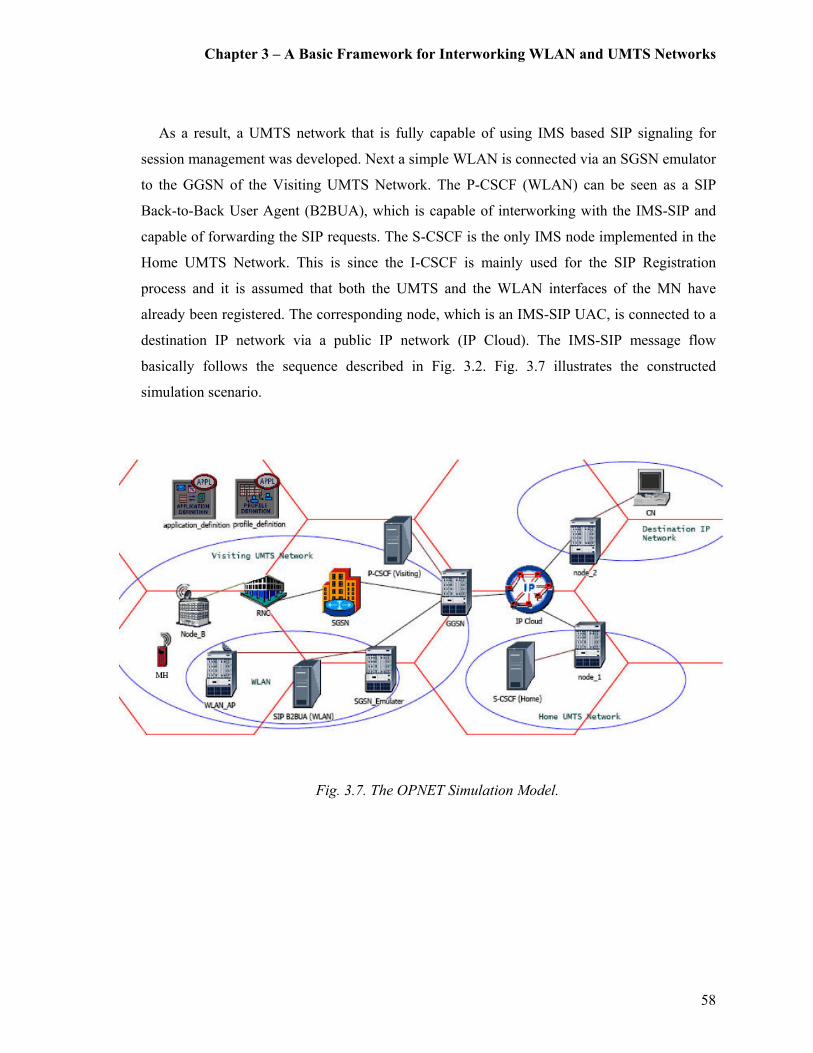
Chapter 3 – A Basic Framework for Interworking WLAN and UMTS Networks
58
As a result, a UMTS network that is fully capable of using IMS based SIP signaling for
session management was developed. Next a simple WLAN is connected via an SGSN emulator
to the GGSN of the Visiting UMTS Network. The P-CSCF (WLAN) can be seen as a SIP
Back-to-Back User Agent (B2BUA), which is capable of interworking with the IMS-SIP and
capable of forwarding the SIP requests. The S-CSCF is the only IMS node implemented in the
Home UMTS Network. This is since the I-CSCF is mainly used for the SIP Registration
process and it is assumed that both the UMTS and the WLAN interfaces of the MN have
already been registered. The corresponding node, which is an IMS-SIP UAC, is connected to a
destination IP network via a public IP network (IP Cloud). The IMS-SIP message flow
basically follows the sequence described in Fig. 3.2. Fig. 3.7 illustrates the constructed
simulation scenario.
Fig. 3.7. The OPNET Simulation Model.
Chapter 3 – A Basic Framework for Interworking WLAN and UMTS Networks
59
3.4.1 Simulation of Vertical Handoff
Using the newly developed IMS-SIP based platform a series of simulations are performed for
evaluating vertical handoff for the previously described scenarios [35]. That is, firstly a make-
before-break handoff (from UMTS to WLAN) and secondly a break-before-make handoff
(WLAN to UMTS) were simulated. It is also important to note the assumptions made when
obtaining these results. Both the UMTS network and the WLAN belong to different IP subnets
where IP addressing and routing were statically assigned. Since there were no multiple
networks available (except for one UMTS and one WLAN), the need for a network selection
algorithm could be eliminated. Therefore, the handoff decisions are individually based on the
signal strength of the WLAN, to which the MN either roams in to or roams out of.
Figure 3.8 indicates the numbers of active IMS-SIP sessions (above) and the corresponding
application traffic flow (below) during a make-before-break handoff from UMTS to WLAN.
This indicates that the proposed architecture is capable of providing acceptable levels of
service continuity during a make-before-break handoff where overlapped coverage is present.
The graphs also indicate the instantaneous presence of dual SIP sessions during the make-
before-break handoff from UMTS to WLAN and a flow of seamless data flow from the UMTS
interface to the WLAN interface. However, there is some indication of data duplication taking
place (when both interfaces are active). This can be easily addressed at higher layers and
therefore lies beyond the scope of this thesis.

Chapter 3 – A Basic Framework for Interworking WLAN and UMTS Networks
60
Fig. 3.8 Numbers of Active IMS-SIP Sessions (above) and Corresponding Application Traffic Flow (below) during a make-before-break Handoff from UMTS to WLAN.
On the other hand, Fig. 3.9 shows the numbers of active IMS-SIP sessions (above) and the
corresponding application traffic flow (below) during a break-before-make type handoff from
WLAN to UMTS during a non-overlapped coverage. The graphs indicate a brief service
disruption delay as the handoff takes place for a non-overlapped coverage environment. Due to
the resultant transient packet loss and delay, seamless continuity of service cannot be
guaranteed, which means that some applications may require re-establishing of sessions.
0
400
800
1200
1600
2000
0 75 150 225 300 375 450 525 600 675 750
Time (Sec.)
Application Traffic Received
(bytes/Sec.)
0
1
2
0 75 150 225 300 375 450 525 600 675 750
Time (Sec.)
IMS-SIP Active Call Sessions
UMTS WLAN
UMTS
UMTS WLAN
UMTS
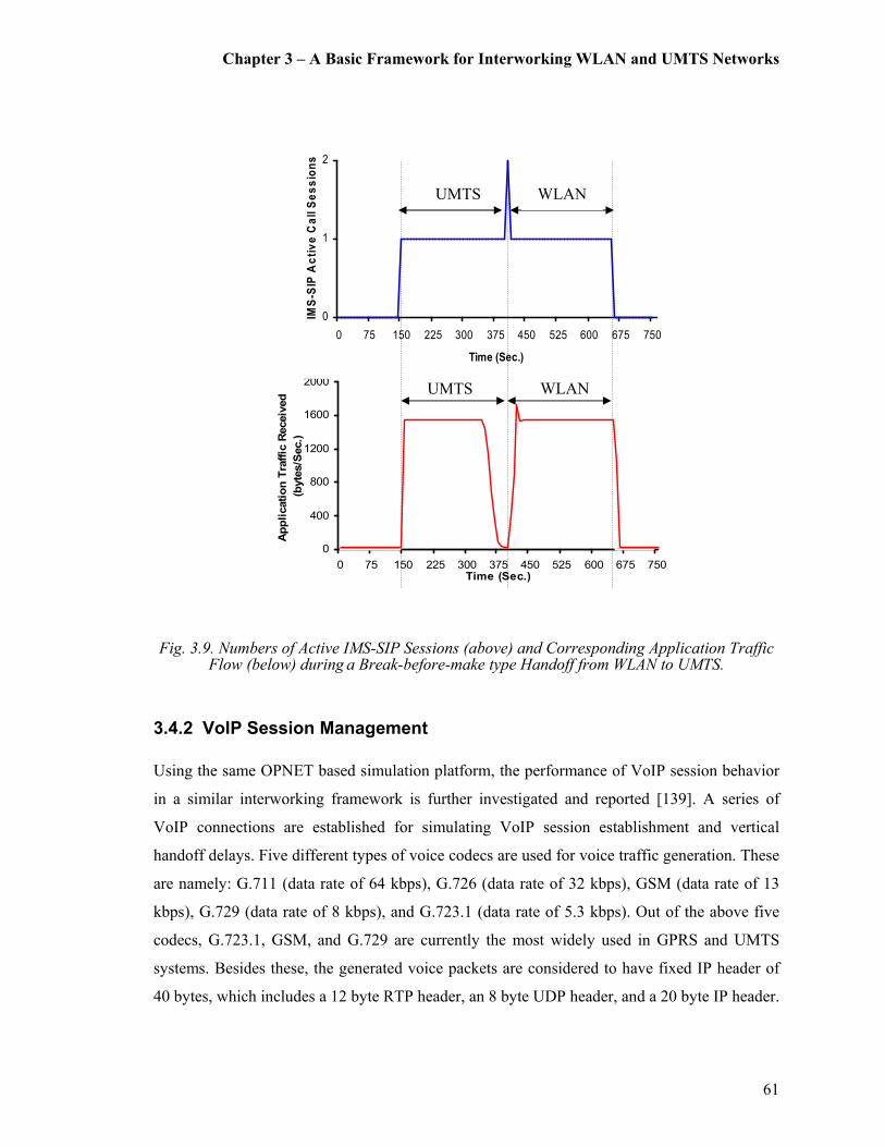
Chapter 3 – A Basic Framework for Interworking WLAN and UMTS Networks
61
Fig. 3.9. Numbers of Active IMS-SIP Sessions (above) and Corresponding Application Traffic
Flow (below) during a Break-before-make type Handoff from WLAN to UMTS.
3.4.2 VoIP Session Management
Using the same OPNET based simulation platform, the performance of VoIP session behavior
in a similar interworking framework is further investigated and reported [139]. A series of
VoIP connections are established for simulating VoIP session establishment and vertical
handoff delays. Five different types of voice codecs are used for voice traffic generation. These
are namely: G.711 (data rate of 64 kbps), G.726 (data rate of 32 kbps), GSM (data rate of 13
kbps), G.729 (data rate of 8 kbps), and G.723.1 (data rate of 5.3 kbps). Out of the above five
codecs, G.723.1, GSM, and G.729 are currently the most widely used in GPRS and UMTS
systems. Besides these, the generated voice packets are considered to have fixed IP header of
40 bytes, which includes a 12 byte RTP header, an 8 byte UDP header, and a 20 byte IP header.
0
400
800
1200
1600
2000
0 75 150 225 300 375 450 525 600 675 750Time (Sec.)
Application Traffic Received
(bytes/Sec.)
0
1
2
0 75 150 225 300 375 450 525 600 675 750
Time (Sec.)
IMS-SIP Active Call Sessions
UMTS WLAN
UMTS
UMTS WLAN
UMTS
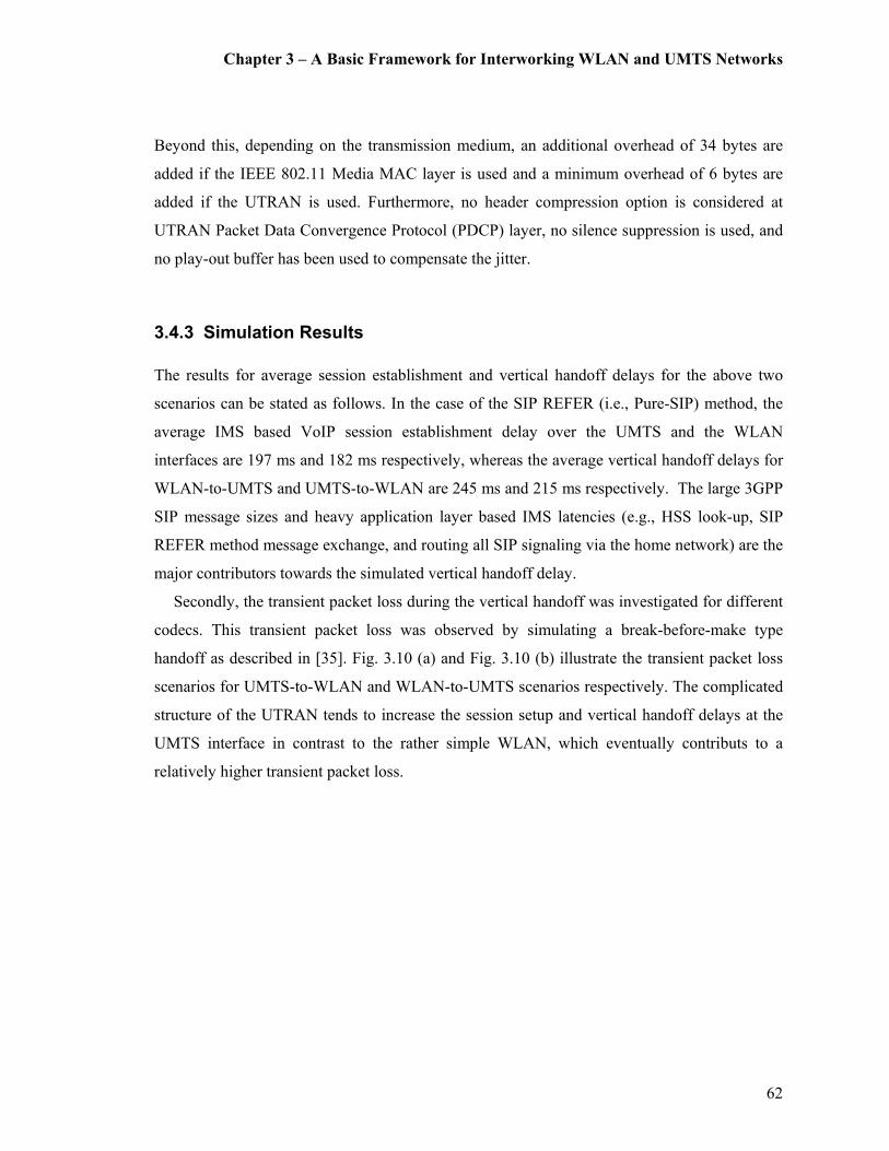
Chapter 3 – A Basic Framework for Interworking WLAN and UMTS Networks
62
Beyond this, depending on the transmission medium, an additional overhead of 34 bytes are
added if the IEEE 802.11 Media MAC layer is used and a minimum overhead of 6 bytes are
added if the UTRAN is used. Furthermore, no header compression option is considered at
UTRAN Packet Data Convergence Protocol (PDCP) layer, no silence suppression is used, and
no play-out buffer has been used to compensate the jitter.
3.4.3 Simulation Results
The results for average session establishment and vertical handoff delays for the above two
scenarios can be stated as follows. In the case of the SIP REFER (i.e., Pure-SIP) method, the
average IMS based VoIP session establishment delay over the UMTS and the WLAN
interfaces are 197 ms and 182 ms respectively, whereas the average vertical handoff delays for
WLAN-to-UMTS and UMTS-to-WLAN are 245 ms and 215 ms respectively. The large 3GPP
SIP message sizes and heavy application layer based IMS latencies (e.g., HSS look-up, SIP
REFER method message exchange, and routing all SIP signaling via the home network) are the
major contributors towards the simulated vertical handoff delay.
Secondly, the transient packet loss during the vertical handoff was investigated for different
codecs. This transient packet loss was observed by simulating a break-before-make type
handoff as described in [35]. Fig. 3.10 (a) and Fig. 3.10 (b) illustrate the transient packet loss
scenarios for UMTS-to-WLAN and WLAN-to-UMTS scenarios respectively. The complicated
structure of the UTRAN tends to increase the session setup and vertical handoff delays at the
UMTS interface in contrast to the rather simple WLAN, which eventually contributs to a
relatively higher transient packet loss.

Chapter 3 – A Basic Framework for Interworking WLAN and UMTS Networks
63
Fig. 3.10. Transient Packet Loss during Vertical Handoff.
0
10
20
30
40
50
1 2 3 4 5 6
Number of Handoffs
Packet Loss (KBytes)
G.711
G.726
GSM
G.729
G.723.1
(a). UMTS-to-WLAN Handoff.
0
20
40
60
80
100
120
1 2 3 4 5 6
Number of Handoffs
Packet Loss (KBytes)
G.711
G.726
GSM
G.729
G.723.1
(b). WLAN-to-UMTS Handoff.
Chapter 3 – A Basic Framework for Interworking WLAN and UMTS Networks
64
Next, Fig. 3.11 (a) illustrates the end-to-end delay metric investigated for the WLAN and
the UMTS interfaces. This is dependent on the end-to-end VoIP signaling and data paths, the
codec, and the payload size of the packets. In fact, the delays from the end points to the codecs
at both ends, the encoder (processing) delay, the algorithmic delay, the packetization delay,
serialization delay, queuing and buffering delay, and the fixed portion of the network delay
yields the end-to-end delay for the connection (i.e., WLAN or UMTS). Note that SIP REFER
method does not have an impact on this metric. Furthermore, longer packetization intervals
(sampling periods) result in creating relatively larger voice payloads. These relatively large
payloads with proportionately smaller IP header overheads lead to better bandwidth utilization.
However, as the period of time required for constructing a single packet increases, the amount
of time it takes for this packet to reach the other end and be decoded increases as well. Thus it
can be said that longer packetization intervals may lead to higher latencies. This phenomenon
is demonstrated in the case of codec G.723.1 (sampling period 30 ms) in Fig. 3.11 (a).
Additionally, the fact that G.723.1 is a codec that requires very high processor powers to
provide high quality audio compression has also contributed to its increase in end-to-end delay.
Jitter, the variation of delay, is another factor which affects delay, especially during a vertical
handoff (when the link capacity changes and so on). The jitter is illustrated by Fig. 3.11 (b).
Chapter 3 – A Basic Framework for Interworking WLAN and UMTS Networks
65
Fig. 3.11. End-to-End Delay and Jitter.
It is evident from these simulation results that the voice capacity over a heterogeneous
network is a function of the system parameters, transmission rate, voice packet payload length
(depending on the codec used), and sampling period. The G.723.1 and G.729 codecs appears to
have the worst end-to-end delays. However, this can be easily overlooked since they are way
below the ITU’s recommendation for one-way end-to-end delay threshold of 150ms [140].
10
20
30
40
50
60
70
G.711 G.723.1 G.726 G.729 GSMCodec Type
End-to-End D
elay (ms)
WLAN
UMTS
(a). Average End-to-End Delay over WLAN and UMTS.
10
10.1
10.2
10.3
10.4
10.5
10.6
10.7
G.711 G.723.1 G.726 G.729 GSM
Codec Type
Jitter (m
s)
(b). Average Jitter -Variation of Delay at Vertical
Handoff.
Chapter 3 – A Basic Framework for Interworking WLAN and UMTS Networks
66
Furthermore, G.723.1 and G.729 also have the lowest jitter values. On the other hand, G.711
and G.726 result in relatively high transient packet loss and packet delay variation during
vertical handoffs. Therefore, since G.723.1 shows the lowest transient packet loss and jitter, it
can be selected as the most appropriate scheme for the considered heterogeneous networking
framework.
3.5 Analytical Modeling
Next an analytical model is derived for evaluating the proposed scheme for analyzing the QoS
metrics and measures involved in call or session mobility management [38]. More precisely,
QoS metrics that are analyzed are handoff delay, average packet loss, jitter and signaling
overhead/cost. The primary assumption made for this analysis is that, VoIP call/session arrivals
follow a Poisson process. However, despite the closeness and the attractiveness of the Poisson
model, the validity of a Poisson process for modeling VoIP call arrivals over a packet
switching IP backbone has often been questioned [141], [142]. The reason being that there is a
wealth of evidence proving that Internet traffic is bursty in nature, which could be best
characterized as self-similar with long range dependence [143], [144] , [145].
However, the reasons for our assumption (i.e., VoIP call/session arrivals follow a Poisson
process) can be justified as follows. Although streaming flows (e.g., voice or video for real-
time play) and aggregates of elastic flows (e.g., email, web browsing, MP3 or MP4 track)
typically exhibit properties of long-range dependence and self-similarity [145], it has been
argued in [146] that modeling VoIP session arrivals to be Poisson may be an adequate
assumption according to the conclusions of [147], especially when the system utilization is
relatively low. This is because all user initiated VoIP sessions display the essential defining
characteristic of being mutually independent [148], [149], [150]. Therefore, as shown in [151]
and [152], for large populations, where each user independently contributes to a small portion
of the overall traffic, user sessions (i.e., human initiated call/data sessions) can be assumed to
follow a Poisson arrival process [153]. Furthermore, based on the traces of wide-area traffic,
there is further evidence that Poisson arrivals appear to be suitable for traffic at the session
level when sessions are human initiated [144].

Chapter 3 – A Basic Framework for Interworking WLAN and UMTS Networks
67
On the other hand, for analysis and design, using bursty background traffic is not practical
as a network element with a non-Poisson arrival (say, Pareto) rate makes it difficult to
approximate the delay leading to an intractable analytical solution [146].
3.5.1 Handoff Delay
In this section, a formula is derived for analyzing the vertical session handoff delay (at the core
network level regardless of the underlying radio network and link layer delays) for the
architecture in Fig. 3.1. The derived method will be successfully applicable for analyzing
vertical session handoff delay from WLAN-to-UMTS and vice-versa for a considered VoIP
data session.
A standard end-to-end vertical handoff delay (D, say) during mid-session mobility consists
of the following sub-procedures (or delays); D1 = Link Layer handoff delay, D2 = movement
detection delay, D3 = address allocation delay, D4 = session re-configuration delay, and D5 =
packet re-transmission delay [154]. The vertical handoff delay/s at the Network Layer (and
above) are calculated independent of the Link Layer delay D1 and mainly consist of D3 and D4.
According to our proposed architecture for IMS based vertical handoff in Fig. 3.1, there is no
Domain Host Configuration Protocol (DHCP) related address allocation. This is due to
relatively high latency involved in DHCP address negotiation and allocation in an interworked
WLAN-UMTS configuration scenario (approx. between 1-2 seconds) [155], which may lead to
a falsely inflated result for the IMS based session re-configuration delay. Hence it can be
argued that D4 is the main contributor for network layer based vertical handoff delay, D. The
session re-configuration delay, D4 mainly consists of the previously mentioned IMS based
session negotiation and handoff and HSS related message exchange delays.
In order to derive an expression for D, we must first derive an expression for analyzing the
end-to-end transmission delay. Hence, let us assume that the end-to-end transmission delay for
a packet size S sent from network A to network B over a number of hops via a wireless and
wired links to be expressed as:
wwlwwlba LLDDHSD +++=− ),( (3.1)

Chapter 3 – A Basic Framework for Interworking WLAN and UMTS Networks
68
where, Dwl is the total delay at the wireless interface (say, BS), Dw is the total delay at the wired
link, Lwl is the latency of the wireless link, and Lw is the latency of the wired link. In order to
derive Dwl and Dw, as clarified in the beginning of Section 3.5, a M/M/1 queuing model has
been applied to the packet flow of the data session at the wireless BS and other networking
elements of the IMS on the path of signaling and data routing of Fig. 3.1. It is important to note
that to apply the results of M/M/1 analysis, several assumptions must be made. The most
important of them is that the service times that a packet experiences at different nodes are
independent of each other. It has also been found that this independence assumption can be
used in large networks [156]. Using the results from the Queuing Theory, expressions for Dwl
and Dw can be expressed as follows [157]:
( )wlwl
wlDλµ −
=1
(3.2)
where, µwl is the service rate at the wireless interface and λwl is the packet arrival rate at the
wireless interface. For clarity and convenience sake, the units for µwl are changed from
packets/sec to bits/sec. If the probability density function of for packet size, x, in bits be µe-µx
with a mean packet length of 1/µ bits/packet, the capacity of communication channel i be Ci
bits/sec, and the arrival rate for channel i be λwl packets/sec, then the product µCi becomes the
service rate in packets/sec. Therefore, for channel i, we get
( )wli
wlC
Dλµ −
=1
(3.3)
where, Dwl includes both queuing and transmission delays. Also note that the mean packet size
does not depend on the channel as the capacity and the input rates.
On the other hand, when Dw (i.e., total delay at the wired link) is considered, it can be
expressed as a collection of delays experienced at each individual node/multiplexer, which can
be considered as a collection of multiple M/M/1 queues. In such an environment, if the output
of several M/M/1 nodes feed into the input queue of another node, the resulting input process

Chapter 3 – A Basic Framework for Interworking WLAN and UMTS Networks
69
also shows the properties of a Poisson process, with mean equal to the sum of the means of the
feeding process [158], [159].
Therefore, the total wired network delay experienced by a packet can be expressed as:
−= ∑
jjj
j
w
wC
Dλµ
λλ
11
(3.4)
where, λw is the total packet arrival rate to the network, λj is the packet arrival rate at jth node,
and µCj is the service rate in packets/sec at the jth node (Refer Appendix A for proof). Thus by
combining equations (3.1), (3.3) and (3.4) we get:
wwl
jjj
j
wwli
ba LLCC
HSD ++
−+
−= ∑−
λµλ
λλµ
111),( (3.5).
Now, an expression for the vertical handoff delay D can be expressed by applying (3.5) to
the entire IMS signaling flow involved in the vertical handoff mechanism as illustrated in Fig.
3.2. Thus the final expression for D is a combination of the following end-to-end delay
components as indicated in equation (3.6).
D = D(SRefer, HUMTS-WLAN) + D(S202Accept, HUMTS- WLAN)
+ D(SINVITE, H WLAN -CN) + D(S183-SP, H WLAN -CN)
+ D(SNotify, HUMTS- WLAN)+ D(SPRACK, H WLAN -CN)
+ D(SOK, HWLAN -CN) + D(SUPDATE, HWLAN -CN)
+ D(SOK, HWLAN -CN) + D(SACK, HWLAN -CN)
+ D(SOKNotify, HUMTS-WLAN) + ∆ (3.6)
where, ∆ is additional IMS (application layer) latency due to the HSS lookup process. Thus
equation (3.6) is capable of providing the total vertical session handoff delay from UMTS-to-
WLAN in this case. Similarly, vertical session handoff delay from the WLAN-to-UMTS can
also be calculated with appropriate substitutions to equation (3.5).
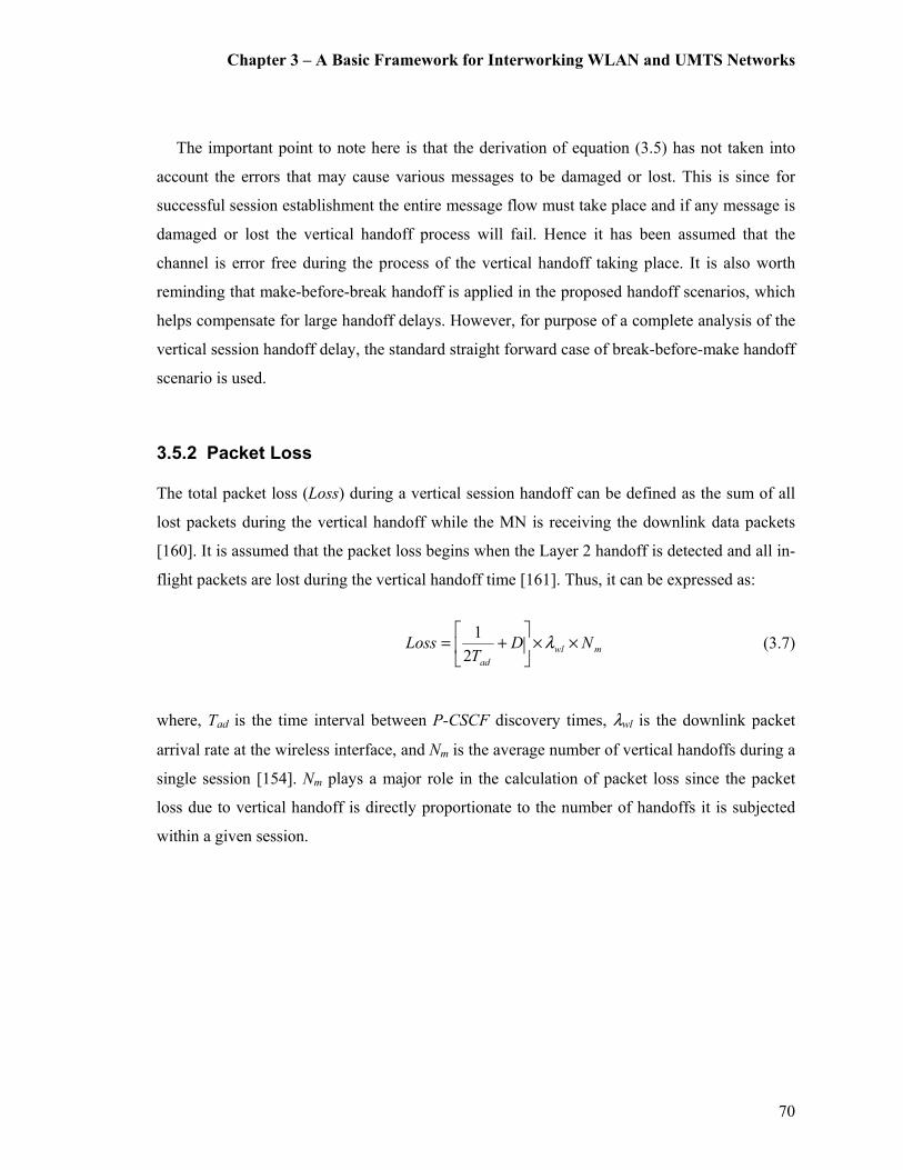
Chapter 3 – A Basic Framework for Interworking WLAN and UMTS Networks
70
The important point to note here is that the derivation of equation (3.5) has not taken into
account the errors that may cause various messages to be damaged or lost. This is since for
successful session establishment the entire message flow must take place and if any message is
damaged or lost the vertical handoff process will fail. Hence it has been assumed that the
channel is error free during the process of the vertical handoff taking place. It is also worth
reminding that make-before-break handoff is applied in the proposed handoff scenarios, which
helps compensate for large handoff delays. However, for purpose of a complete analysis of the
vertical session handoff delay, the standard straight forward case of break-before-make handoff
scenario is used.
3.5.2 Packet Loss
The total packet loss (Loss) during a vertical session handoff can be defined as the sum of all
lost packets during the vertical handoff while the MN is receiving the downlink data packets
[160]. It is assumed that the packet loss begins when the Layer 2 handoff is detected and all in-
flight packets are lost during the vertical handoff time [161]. Thus, it can be expressed as:
mwl
ad
NDT
Loss ××
+= λ
2
1 (3.7)
where, Tad is the time interval between P-CSCF discovery times, λwl is the downlink packet
arrival rate at the wireless interface, and Nm is the average number of vertical handoffs during a
single session [154]. Nm plays a major role in the calculation of packet loss since the packet
loss due to vertical handoff is directly proportionate to the number of handoffs it is subjected
within a given session.
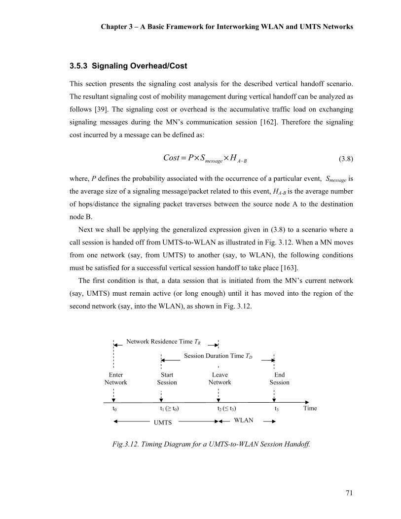
Chapter 3 – A Basic Framework for Interworking WLAN and UMTS Networks
71
3.5.3 Signaling Overhead/Cost
This section presents the signaling cost analysis for the described vertical handoff scenario.
The resultant signaling cost of mobility management during vertical handoff can be analyzed as
follows [39]. The signaling cost or overhead is the accumulative traffic load on exchanging
signaling messages during the MN’s communication session [162]. Therefore the signaling
cost incurred by a message can be defined as:
BAmessage HSPCost −××= (3.8)
where, P defines the probability associated with the occurrence of a particular event, Smessage is
the average size of a signaling message/packet related to this event, HA-B is the average number
of hops/distance the signaling packet traverses between the source node A to the destination
node B.
Next we shall be applying the generalized expression given in (3.8) to a scenario where a
call session is handed off from UMTS-to-WLAN as illustrated in Fig. 3.12. When a MN moves
from one network (say, from UMTS) to another (say, to WLAN), the following conditions
must be satisfied for a successful vertical session handoff to take place [163].
The first condition is that, a data session that is initiated from the MN’s current network
(say, UMTS) must remain active (or long enough) until it has moved into the region of the
second network (say, into the WLAN), as shown in Fig. 3.12.
Fig.3.12. Timing Diagram for a UMTS-to-WLAN Session Handoff.
Time t3 t2 (≤ t3) t1 (≥ t0) t0
Enter
Network
Start
Session
Leave
Network
End
Session
Network Residence Time TR
Session Duration Time TD
UMTS WLAN

Chapter 3 – A Basic Framework for Interworking WLAN and UMTS Networks
72
Based on this condition, P1(t), the arrival probability of a session that is likely to be
subjected to a vertical handoff for an inter-network roaming MN can be derived. Let’s assume
that session arrivals follow Poisson process with the average session arrival rate λ calls/min,
thus the probability that there is one session arrival in a time period t becomes tte λλ − [156].
Hence, P1, the session arrival probability for an inter-network roaming MN when it is resident
in the UMTS network (i.e., according to Fig. 3.12), can be expressed as:
∫ −=2
0
1 )()(
t
T
t dttftetPR
λλ (3.9)
where, )(tfRT
is the probability density function (pdf) of the network residence time TR. It is
assumed that the residence time of the MN in a given network, TR, is exponentially distributed
with a mean 1/η, where η is the inter-network mobility rate. Hence )(tfRT
is expressed as:
t
T etfR
ηη −=)( (3.10)
Further, as per the justification used in [163], since the maximum limit for t2 can be
extended until the end of the session, in order to obtain a closed form value for P1, the upper
limit of the integral in (3.9) is changed to ∞. By substituting )(tfRT
in (3.9) and solving the
equation P1 can be derived as:
∫∞
−−=0
1 )( dtetetP tt ηλ ηλ
∫∞
+−=0
)(
1 )( dttetP tηλλη
( ) ( )
+−−
+−= ∫
∞ +−∞
+−
0
)(
0
)(
.1. dtete tt
µλµλλη
ηληλ
[ ]
( )
++
+= ∫∞
+−
0
)(10 dte tηλ
µλλη
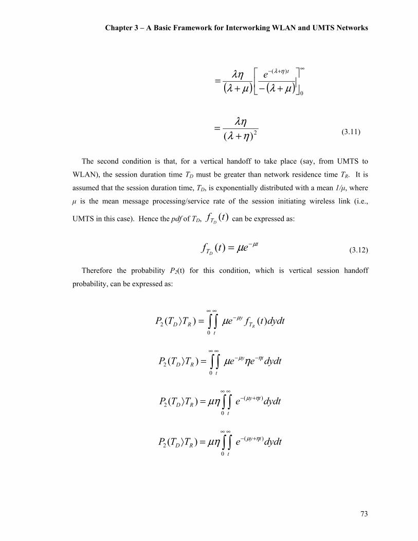
Chapter 3 – A Basic Framework for Interworking WLAN and UMTS Networks
73
( ) ( )
∞+−
+−+=
0
)(
µλµλ
λη ηλ te
2)( ηλ
λη
+= (3.11)
The second condition is that, for a vertical handoff to take place (say, from UMTS to
WLAN), the session duration time TD must be greater than network residence time TR. It is
assumed that the session duration time, TD, is exponentially distributed with a mean 1/µ, where
µ is the mean message processing/service rate of the session initiating wireless link (i.e.,
UMTS in this case). Hence the pdf of TD, )(tfDT can be expressed as:
t
T etfD
µµ −=)( (3.12)
Therefore the probability P2(t) for this condition, which is vertical session handoff
probability, can be expressed as:
∫ ∫∞
−∞
=⟩0
2 )()( dydttfeTTPRT
y
t
RD
µµ
∫ ∫∞
−−∞
=⟩0
2 )( dydteeTTP ty
t
RD
ηµ ηµ
∫ ∫∞
+−∞
=⟩0
)(
2 )( dydteTTP ty
t
RD
ηµµη
∫ ∫∞
+−∞
=⟩0
)(
2 )( dydteTTP ty
t
RD
ηµµη

Chapter 3 – A Basic Framework for Interworking WLAN and UMTS Networks
74
∫∞ ∞
+−
−=⟩
0
)(
2 )( dte
TTP
t
ty
RDµ
µηηµ
∫∞
+−=⟩0
)(
2 )( dteTTP t
RD
ηµη
∞+−
+−=⟩
0
)(
2)(
)(ηµ
ηηµ t
RD
eTTP
)(2
ηµ
η
+=P (3.13)
For the sake of clarity and convenience, the units for µ (i.e., the mean message
processing/service rate of the session initiating wireless link) are changed from packets/sec to
bits/sec as in equation (3.3), where Ci is the capacity of the communication channel i in
bits/sec.
)(2
ηµ
η
+=
iwlCP (3.14)
Therefore, the total signaling cost for the scenario in Fig.3.2 can be expressed as the sum of
the two individual signaling costs associated with the above two conditions. Thus, P1 and P2
are substituted for P in the generalized expression given in (3.8) for calculating these individual
signaling costs. Additionally, since the signaling cost is calculated for a roaming MN, the
average network mobility rate (η) and the average session arrival rate (λ) components are also
included in the final equation. The SIP INVITE message sequence (steps 1-7 from Fig. 3.2) is
associated with P1 and session arrival rate. Similarly, the SIP REFER message sequence (steps
8-14 from Fig. 3.2) is associated with P2 and inter-network mobility rate.

Chapter 3 – A Basic Framework for Interworking WLAN and UMTS Networks
75
Hence, the total signaling overhead incurred by vertical handoffs during a given data session
can be expressed as:
( ) ( )∑∑=
−=
− ×+×=21
1
)(2
1
)(1
n
i
BAREFER
n
i
BAINVITE iiiiHSPHSPCost ηλ (3.15)
where n1 and n2 represent the number of messages involved in each handoff/message exchange
sequence as illustrated in Fig. 3.2. If η is the average network mobility rate of a MN and λ is
the average session arrival rate, λ/η may be defined as the Call-to-Mobility Ratio (CMR) [164],
[165]. Thus (3.15) can be re-arranged as:
( ) ( )∑∑=
−
=
− ×+
×=
21
1
)(2
1
)(1
n
i
BAREFER
n
i
BAINVITE iiiiHSPHSPCost η
η
λη (3.16)
( ) ( )∑∑=
−
=
− ×+
×=
21
1
)(2
1
)(1
n
i
BAREFER
n
i
BAINVITE iiiiHSPCMRHSPCost ηη (3.17)
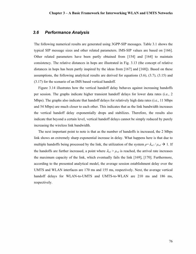
Chapter 3 – A Basic Framework for Interworking WLAN and UMTS Networks
76
3.6 Performance Analysis
The following numerical results are generated using 3GPP-SIP messages. Table 3.1 shows the
typical SIP message sizes and other related parameters. IMS-SIP values are based on [166].
Other related parameters have been partly obtained from [154] and [164] to maintain
consistency. The relative distances in hops are illustrated in Fig. 3.13 (the concept of relative
distances in hops has been partly inspired by the ideas from [167] and [168]). Based on these
assumptions, the following analytical results are derived for equations (3.6), (3.7), (3.15) and
(3.17) for the scenario of an IMS based vertical handoff.
Figure 3.14 illustrates how the vertical handoff delay behaves against increasing handoffs
per session. The graphs indicate higher transient handoff delays for lower data rates (i.e., 2
Mbps). The graphs also indicate that handoff delays for relatively high data rates (i.e., 11 Mbps
and 54 Mbps) are much closer to each other. This indicates that as the link bandwidth increases
the vertical handoff delay exponentially drops and stabilizes. Therefore, the results also
indicate that beyond a certain level, vertical handoff delays cannot be simply reduced by purely
increasing the wireless link bandwidth.
The next important point to note is that as the number of handoffs is increased, the 2 Mbps
link shows an extremely sharp exponential increase in delay. What happens here is that due to
multiple handoffs being processed by the link, the utilization of the system ρ=λwl / µwl � 1. If
the handoffs are further increased, a point where λwl > µwl is reached, the arrival rate increases
the maximum capacity of the link, which eventually fails the link [169], [170]. Furthermore,
according to the presented analytical model, the average session establishment delay over the
UMTS and WLAN interfaces are 170 ms and 155 ms, respectively. Next, the average vertical
handoff delays for WLAN-to-UMTS and UMTS-to-WLAN are 210 ms and 186 ms,
respectively.
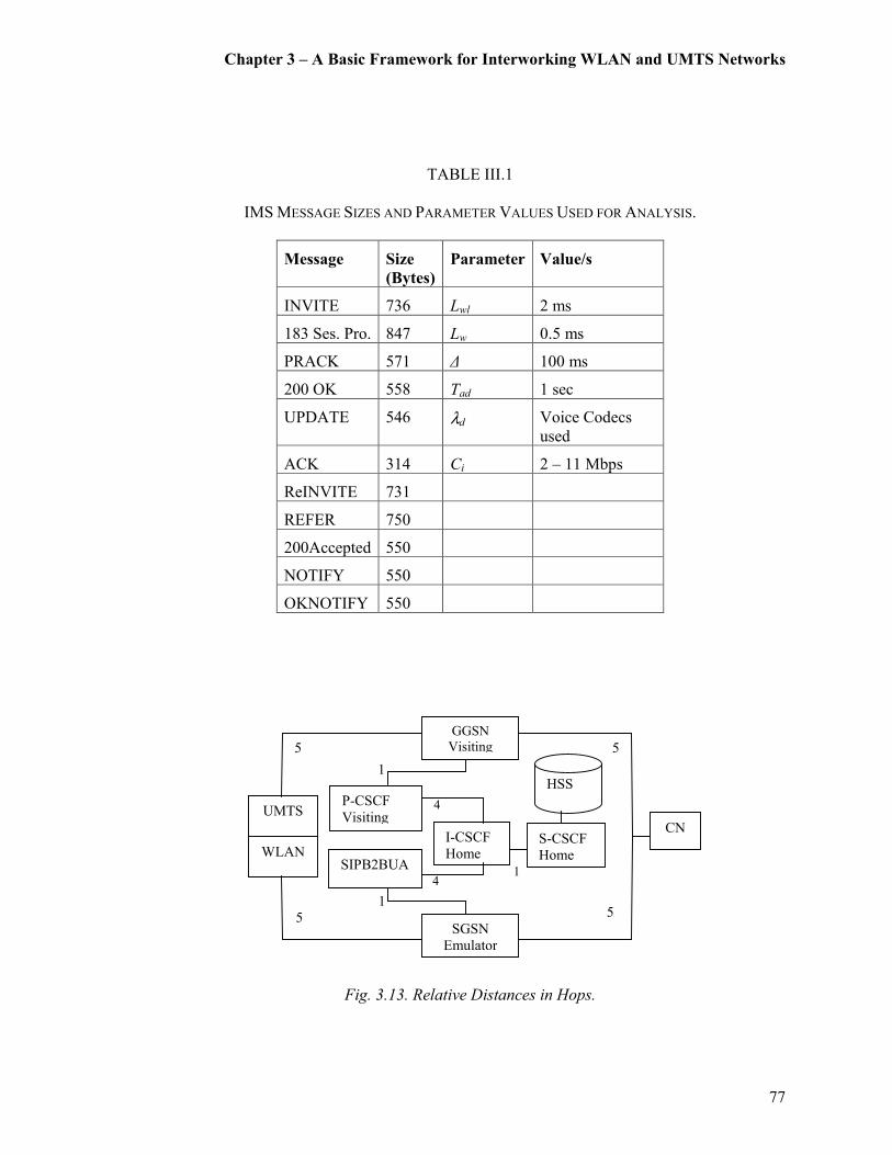
Chapter 3 – A Basic Framework for Interworking WLAN and UMTS Networks
77
TABLE III.1
IMS MESSAGE SIZES AND PARAMETER VALUES USED FOR ANALYSIS.
Message Size
(Bytes)
Parameter Value/s
INVITE 736 Lwl 2 ms
183 Ses. Pro. 847 Lw 0.5 ms
PRACK 571 ∆ 100 ms
200 OK 558 Tad 1 sec
UPDATE 546 λd Voice Codecs
used
ACK 314 Ci 2 – 11 Mbps
ReINVITE 731
REFER 750
200Accepted 550
NOTIFY 550
OKNOTIFY 550
Fig. 3.13. Relative Distances in Hops.
1
4
4 1
5
5
5
5
1
UMTS
GGSN
Visiting
P-CSCF
Visiting
WLAN SIPB2BUA
I-CSCF
Home S-CSCF
Home
SGSN
Emulator
CN
HSS
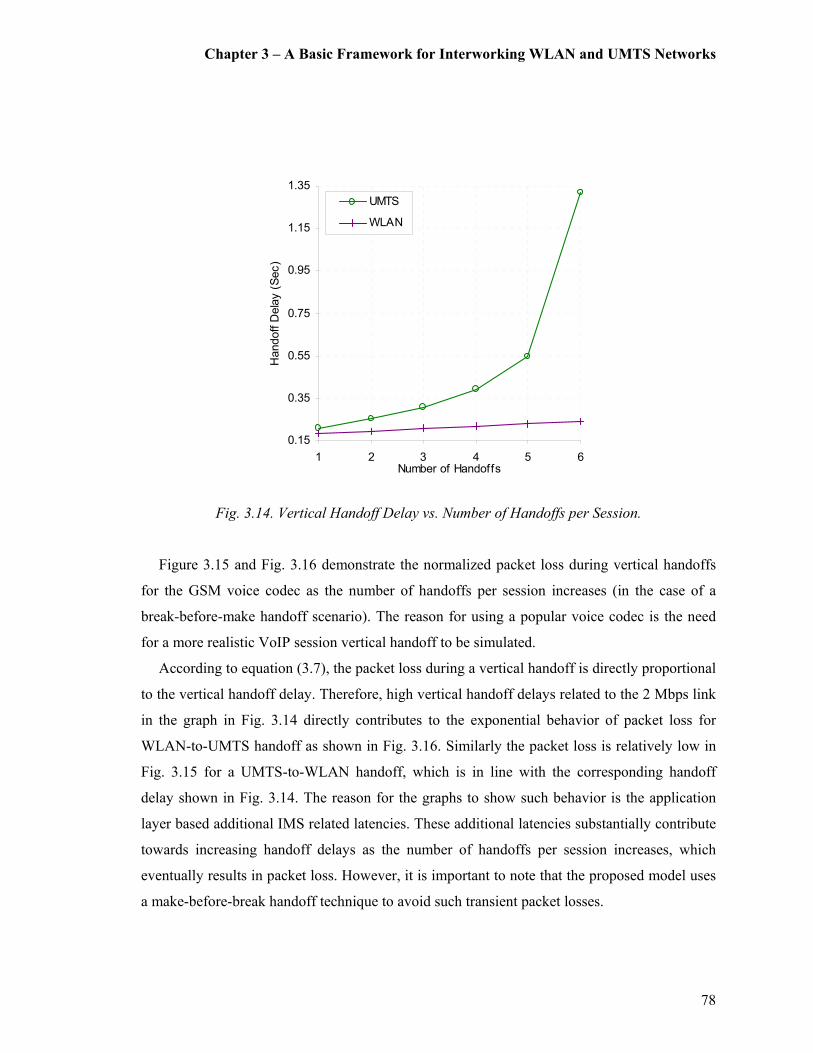
Chapter 3 – A Basic Framework for Interworking WLAN and UMTS Networks
78
0.15
0.35
0.55
0.75
0.95
1.15
1.35
1 2 3 4 5 6Number of Handoffs
Handoff D
elay (Sec)
UMTS
WLAN
Fig. 3.14. Vertical Handoff Delay vs. Number of Handoffs per Session.
Figure 3.15 and Fig. 3.16 demonstrate the normalized packet loss during vertical handoffs
for the GSM voice codec as the number of handoffs per session increases (in the case of a
break-before-make handoff scenario). The reason for using a popular voice codec is the need
for a more realistic VoIP session vertical handoff to be simulated.
According to equation (3.7), the packet loss during a vertical handoff is directly proportional
to the vertical handoff delay. Therefore, high vertical handoff delays related to the 2 Mbps link
in the graph in Fig. 3.14 directly contributes to the exponential behavior of packet loss for
WLAN-to-UMTS handoff as shown in Fig. 3.16. Similarly the packet loss is relatively low in
Fig. 3.15 for a UMTS-to-WLAN handoff, which is in line with the corresponding handoff
delay shown in Fig. 3.14. The reason for the graphs to show such behavior is the application
layer based additional IMS related latencies. These additional latencies substantially contribute
towards increasing handoff delays as the number of handoffs per session increases, which
eventually results in packet loss. However, it is important to note that the proposed model uses
a make-before-break handoff technique to avoid such transient packet losses.
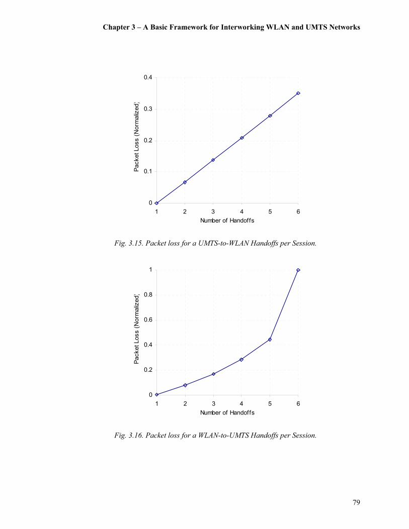
Chapter 3 – A Basic Framework for Interworking WLAN and UMTS Networks
79
0
0.1
0.2
0.3
0.4
1 2 3 4 5 6
Number of Handoffs
Packet Loss (Norm
alized)
Fig. 3.15. Packet loss for a UMTS-to-WLAN Handoffs per Session.
0
0.2
0.4
0.6
0.8
1
1 2 3 4 5 6
Number of Handoffs
Packet Loss (Norm
alized)
Fig. 3.16. Packet loss for a WLAN-to-UMTS Handoffs per Session.

Chapter 3 – A Basic Framework for Interworking WLAN and UMTS Networks
80
Figure 3.17 illustrates the behavior of the jitter during vertical handoffs, which is the
variation of delay, for the same voice codec. The jitter is simulated by using (3.5) for
calculating the end-to-end delay for a given codec over the given link and plotting the variation
of delay when a session is handed off from UMTS to WLAN. According to the graphs in Fig.
3.17, the jitter levels are within acceptable limits for a VoIP session as specified in many
Service Level Agreements (SLA) [171], [172], [173] .
However, as the number of vertical handoffs increases, the interesting fact is that these jitter
graph tend to indicate rather exponential curves. This could well be confirmed from Fig. 3.18,
which illustrates the behavior of jitter for an extended number of session handoffs. This
phenomenon can also be easily explained as in the previous case. That is, when the number of
VoIP sessions keep increasing there comes a point where ρ=λwl / µwl � 1, which increases
delay exponentially and so does jitter.
8
9
10
11
12
13
14
0 2 4 6 8 10Number of Handoffs
Jitter (m
s)
Fig. 3.17. Variation of End-to-End Delay (Jitter).
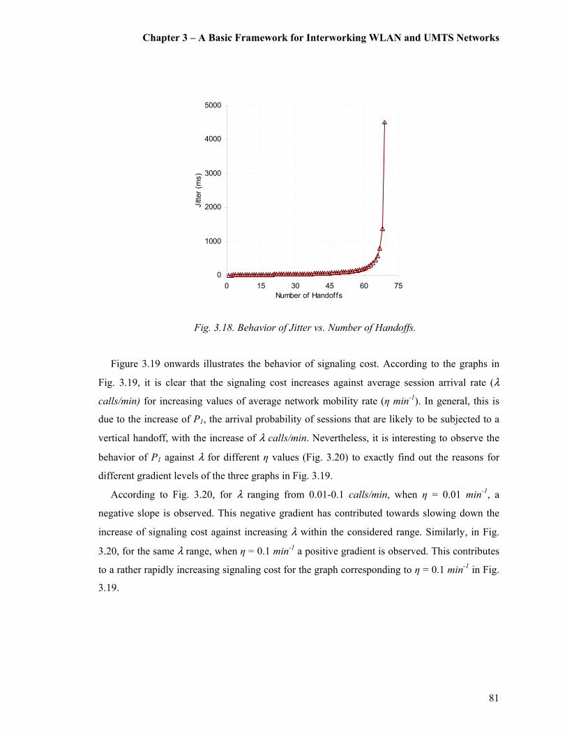
Chapter 3 – A Basic Framework for Interworking WLAN and UMTS Networks
81
0
1000
2000
3000
4000
5000
0 15 30 45 60 75
Number of Handoffs
Jitter (m
s)
Fig. 3.18. Behavior of Jitter vs. Number of Handoffs.
Figure 3.19 onwards illustrates the behavior of signaling cost. According to the graphs in
Fig. 3.19, it is clear that the signaling cost increases against average session arrival rate (λ
calls/min) for increasing values of average network mobility rate (η min-1). In general, this is
due to the increase of P1, the arrival probability of sessions that are likely to be subjected to a
vertical handoff, with the increase of λ calls/min. Nevertheless, it is interesting to observe the
behavior of P1 against λ for different η values (Fig. 3.20) to exactly find out the reasons for
different gradient levels of the three graphs in Fig. 3.19.
According to Fig. 3.20, for λ ranging from 0.01-0.1 calls/min, when η = 0.01 min-1, a
negative slope is observed. This negative gradient has contributed towards slowing down the
increase of signaling cost against increasing λ within the considered range. Similarly, in Fig.
3.20, for the same λ range, when η = 0.1 min-1 a positive gradient is observed. This contributes
to a rather rapidly increasing signaling cost for the graph corresponding to η = 0.1 min-1 in Fig.
3.19.
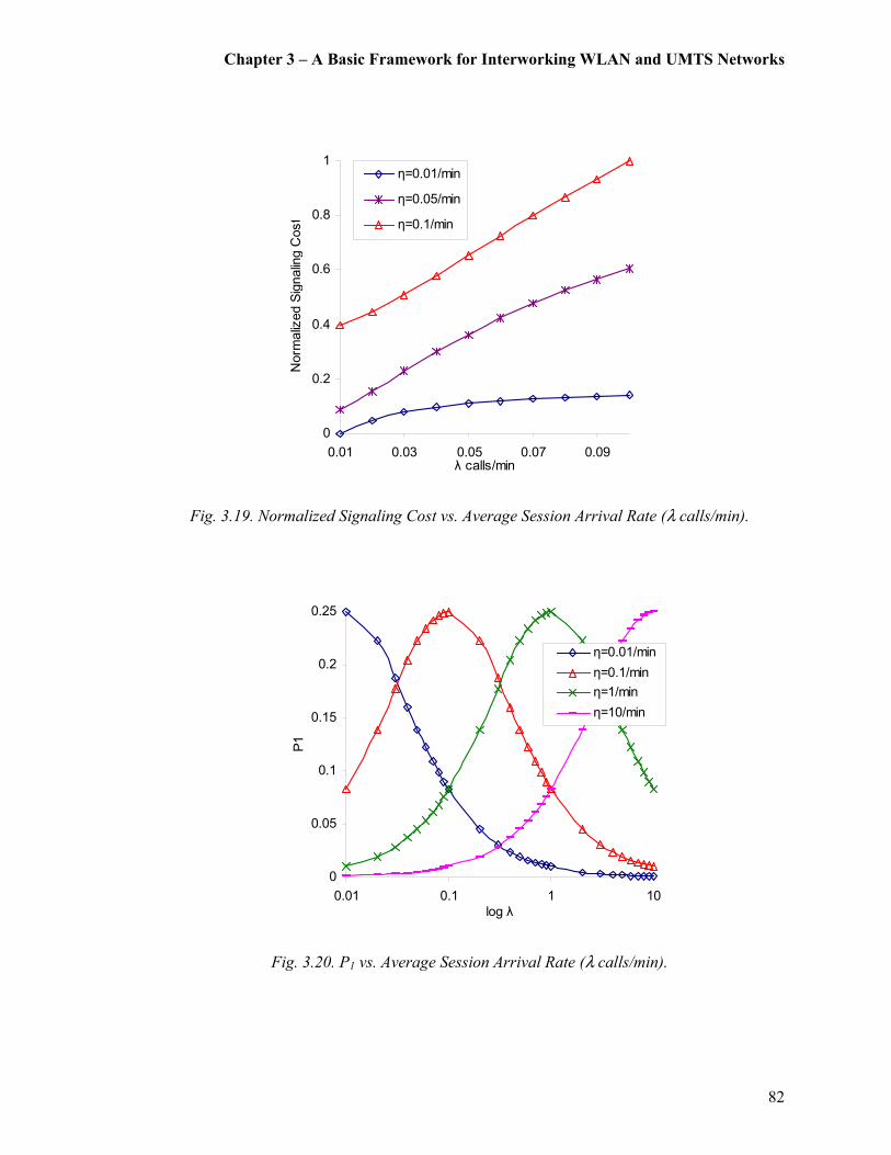
Chapter 3 – A Basic Framework for Interworking WLAN and UMTS Networks
82
0
0.2
0.4
0.6
0.8
1
0.01 0.03 0.05 0.07 0.09λ calls/min
Norm
alized Signaling C
ost
η=0.01/min
η=0.05/min
η=0.1/min
Fig. 3.19. Normalized Signaling Cost vs. Average Session Arrival Rate (λ calls/min).
0
0.05
0.1
0.15
0.2
0.25
0.01 0.1 1 10
log λ
P1
η=0.01/min
η=0.1/min
η=1/min
η=10/min
Fig. 3.20. P1 vs. Average Session Arrival Rate (λ calls/min).
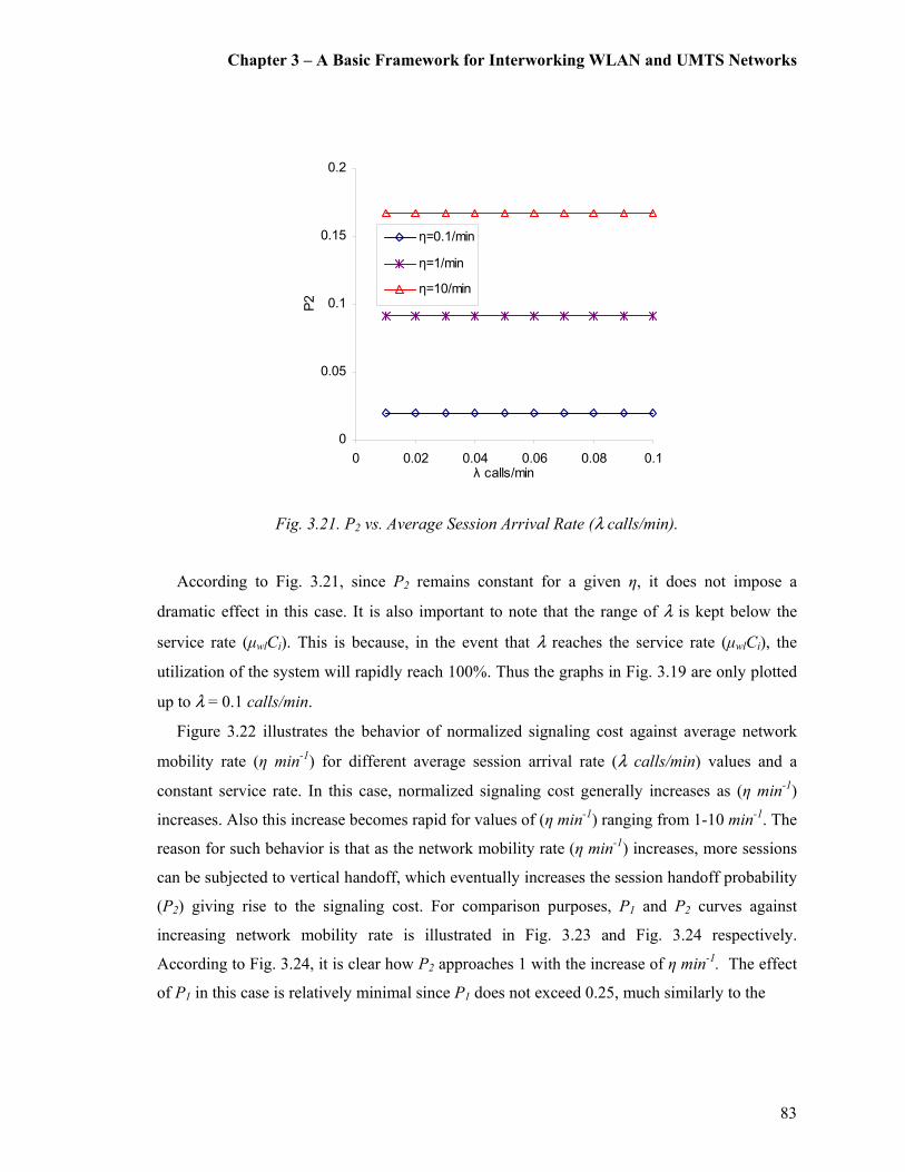
Chapter 3 – A Basic Framework for Interworking WLAN and UMTS Networks
83
0
0.05
0.1
0.15
0.2
0 0.02 0.04 0.06 0.08 0.1λ calls/min
P2
η=0.1/min
η=1/min
η=10/min
Fig. 3.21. P2 vs. Average Session Arrival Rate (λ calls/min).
According to Fig. 3.21, since P2 remains constant for a given η, it does not impose a
dramatic effect in this case. It is also important to note that the range of λ is kept below the
service rate (µwlCi). This is because, in the event that λ reaches the service rate (µwlCi), the
utilization of the system will rapidly reach 100%. Thus the graphs in Fig. 3.19 are only plotted
up to λ = 0.1 calls/min.
Figure 3.22 illustrates the behavior of normalized signaling cost against average network
mobility rate (η min-1) for different average session arrival rate (λ calls/min) values and a
constant service rate. In this case, normalized signaling cost generally increases as (η min-1)
increases. Also this increase becomes rapid for values of (η min-1) ranging from 1-10 min
-1. The
reason for such behavior is that as the network mobility rate (η min-1) increases, more sessions
can be subjected to vertical handoff, which eventually increases the session handoff probability
(P2) giving rise to the signaling cost. For comparison purposes, P1 and P2 curves against
increasing network mobility rate is illustrated in Fig. 3.23 and Fig. 3.24 respectively.
According to Fig. 3.24, it is clear how P2 approaches 1 with the increase of η min-1. The effect
of P1 in this case is relatively minimal since P1 does not exceed 0.25, much similarly to the

Chapter 3 – A Basic Framework for Interworking WLAN and UMTS Networks
84
0
0.2
0.4
0.6
0.8
1
0.01 0.1 1 10log η
Norm
alized Signaling Cost
λ=0.01 calls/min
λ=0.05 calls/min
λ=0.1 calls/min
Fig. 3.22. Normalized Signaling Cost vs. Average Network Mobility Rate (η min-1).
0
0.05
0.1
0.15
0.2
0.25
0.3
0.01 0.1 1 10log η
P1
λ=0.01 calls/min
λ=0.05 calls/min
λ=0.1 calls/min
Fig. 3.23. P1 vs. Average Network Mobility Rate (η min-1).

Chapter 3 – A Basic Framework for Interworking WLAN and UMTS Networks
85
0
0.2
0.4
0.6
0.8
1
0.01 0.1 1 10log η
P2
λ=0.1 calls/min
λ=0.5 calls/min
λ=1 calls/min
Fig. 3.24. P2 vs. Average Network Mobility Rate (η min-1).
pattern indicated in Fig. 3.20 (i.e., since P1 curves behaves the same despite λ calls/min and η
min-1 being interchanged).
The next investigation is the behavior of signaling cost against the CMR. Fig. 3.25
illustrates normalized signaling cost against CMR by having λ calls/min as a constant. As per
the illustration of the graphs in Fig. 3.25, the normalized signaling cost reduces exponentially
as CMR increases. As the CMR increases by keeping λ calls/min as a constant, η min-1 tends to
decrease rapidly, which has a direct impact on P2 that reduces it exponentially against
increasing CMR. However, the impact of decreasing η min-1 does not tend to have a drastic
effect on P1. P1 shows a closely similar pattern as in Fig. 3.20 with a maximum peak of 0.25
for CMR=1. Hence, in this case, the signaling cost curve is shaped according to the behavior
pattern of P2 as CMR increases. Also, it is important to note that the signaling cost is higher for
larger values of λ.
Last but not least, Fig. 3.26 illustrates normalized signaling cost against CMR by having η
min-1 as a constant. As per the illustration of the graphs in Fig. 3.26, the normalized signaling
cost increases as CMR increases and eventually reaches a saturation point. As the CMR
increases by keeping η min-1 as a constant, λ calls/min tends to increase rapidly, which

Chapter 3 – A Basic Framework for Interworking WLAN and UMTS Networks
86
0
0.1
0.2
0.3
0.4
0.5
0.6
0.7
0.8
0.9
1
0.1 1 10
log CMR
Norm
alized Signaling C
ost
λ=0.01 calls/min
λ=0.05 calls/min
λ=0.1 calls/min
Fig. 3.25. Normalized Signaling Cost vs. CMR (λ constant).
0
0.2
0.4
0.6
0.8
1
0.1 1 10log CMR
Norm
alized Signaling C
ost
η=0.01 /min
η=0.05 /min
η=0.1 /min
Fig. 3.26. Normalized Signaling Cost vs. CMR (η constant).

Chapter 3 – A Basic Framework for Interworking WLAN and UMTS Networks
87
eventually results in increasing the signaling cost. As in the above case, P1 behaves in a similar
manner with a maximum peak of 0.25 for CMR=1. However, the notable point is that P2
remains constant for a given value of η, which eventually contributes towards shaping the
signaling cost curves by reaching a saturation level. Furthermore, signaling cost is also higher
for larger values of η.
It must also be noted that the above analysis and results have been obtained for users
moving with randomized patterns independently to each other. However, there may be
instances where additional correlation exists amongst users, which leads to aggregation of their
movements, namely the group mobility [174], [175]. This leads to the exploration of advanced
mobility models for realistically characterizing group mobility. In group mobility, each group
has a logical center, which generally defines the group trajectory. Usually, users are considered
to have random mobility with respect to a logical center and be randomly distributed within the
geographic scope of the group [176]. The movement of the logical center could be defined by a
predefined motion path or an individual mobility model [177]. If it is a predefined motion path,
the movement of the centers will not be random [178]. However, as a special case scenario of
group mobility, if the movements of these logical centers behave according to a random walk
mobility model [179], it could be argued that such a scenario may be closely approximated to
our analyzed mobility model [180].
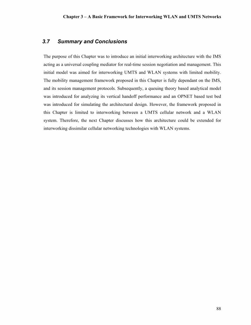
Chapter 3 – A Basic Framework for Interworking WLAN and UMTS Networks
88
3.7 Summary and Conclusions
The purpose of this Chapter was to introduce an initial interworking architecture with the IMS
acting as a universal coupling mediator for real-time session negotiation and management. This
initial model was aimed for interworking UMTS and WLAN systems with limited mobility.
The mobility management framework proposed in this Chapter is fully dependant on the IMS,
and its session management protocols. Subsequently, a queuing theory based analytical model
was introduced for analyzing its vertical handoff performance and an OPNET based test bed
was introduced for simulating the architectural design. However, the framework proposed in
this Chapter is limited to interworking between a UMTS cellular network and a WLAN
system. Therefore, the next Chapter discusses how this architecture could be extended for
interworking dissimilar cellular networking technologies with WLAN systems.

Chapter 4 – An Extended Framework for Interworking WLAN, UMTS
and CDMA2000 Networks
89
V{tÑàxÜ G An Extended Framework for Interworking WLAN, UMTS and
CDMA2000 Networks
This Chapter focuses on extending the proposed WLAN-UMTS interworking architecture
presented in Chapter 3 to a unified framework for interworking dissimilar 3G cellular
networking standards. As a result, global roaming and interoperability beyond one cellular
system (say, UMTS) to another cellular system (say, CDMA2000) will become possible. The
Chapter is organized as follows. Firstly the introduction section outlines the motivation for this
work and the importance of a heterogeneous interworking framework. Followed by this comes
the sections on IMS based mobility management in 3G cellular networks and related
architectural considerations. The next section outlines the proposed extended architecture.
Subsequently the sections on analytical modeling and performance evaluations are presented.
Finally an OPNET based simulation model is introduced for validation of the performance. The
contents provided under this Chapter have contributed to the following publications. The
interworking architecture and the OPNET simulation platform presented in this Chapter has
contributed to [40] and the presented OPNET simulation results have partly contributed to [41]
and [42].
4.1 Introduction
One of the main motivations behind the development process of the NGMN is to have a
common platform for different cellular technologies to interwork with each other [181]. In
order to address this requirement, previously proposed WLAN-UMTS interworking framework
has been extended where a common platform is proposed for coupling a CDMA2000 network
at the core network. As elaborated in Chapter 3, the novelty of this solution for WLAN-UMTS
interworking is its adaptation of the 3GPP’s IMS as an arbitrator for real-time session
negotiation and management [31]. Since 3GPP2 also adopts a similar concept as 3GPP by
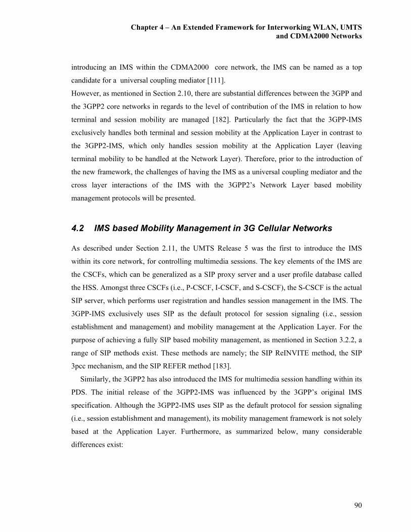
Chapter 4 – An Extended Framework for Interworking WLAN, UMTS
and CDMA2000 Networks
90
introducing an IMS within the CDMA2000 core network, the IMS can be named as a top
candidate for a universal coupling mediator [111].
However, as mentioned in Section 2.10, there are substantial differences between the 3GPP and
the 3GPP2 core networks in regards to the level of contribution of the IMS in relation to how
terminal and session mobility are managed [182]. Particularly the fact that the 3GPP-IMS
exclusively handles both terminal and session mobility at the Application Layer in contrast to
the 3GPP2-IMS, which only handles session mobility at the Application Layer (leaving
terminal mobility to be handled at the Network Layer). Therefore, prior to the introduction of
the new framework, the challenges of having the IMS as a universal coupling mediator and the
cross layer interactions of the IMS with the 3GPP2’s Network Layer based mobility
management protocols will be presented.
4.2 IMS based Mobility Management in 3G Cellular Networks
As described under Section 2.11, the UMTS Release 5 was the first to introduce the IMS
within its core network, for controlling multimedia sessions. The key elements of the IMS are
the CSCFs, which can be generalized as a SIP proxy server and a user profile database called
the HSS. Amongst three CSCFs (i.e., P-CSCF, I-CSCF, and S-CSCF), the S-CSCF is the actual
SIP server, which performs user registration and handles session management in the IMS. The
3GPP-IMS exclusively uses SIP as the default protocol for session signaling (i.e., session
establishment and management) and mobility management at the Application Layer. For the
purpose of achieving a fully SIP based mobility management, as mentioned in Section 3.2.2, a
range of SIP methods exist. These methods are namely; the SIP ReINVITE method, the SIP
3pcc mechanism, and the SIP REFER method [183].
Similarly, the 3GPP2 has also introduced the IMS for multimedia session handling within its
PDS. The initial release of the 3GPP2-IMS was influenced by the 3GPP’s original IMS
specification. Although the 3GPP2-IMS uses SIP as the default protocol for session signaling
(i.e., session establishment and management), its mobility management framework is not solely
based at the Application Layer. Furthermore, as summarized below, many considerable
differences exist:

Chapter 4 – An Extended Framework for Interworking WLAN, UMTS
and CDMA2000 Networks
91
� In the 3GPP-IMS:
o SIP is used for session mobility,
o IPv6 based core network,
o HSS manages subscriber user data,
o PDP context activation used for P-CSCF discovery, and
o P-CSCF and associated visiting GGSN must reside in the same network.
� In the 3GPP2-IMS:
o MIP (at Network Layer) is used for IP / terminal mobility management and SIP
(at Application Layer) is used for session mobility management,
o Flexibility in using IPv4 or IPv6,
o Home AAA server and databases handle subscriber user information,
o PDP context activation not used for P-CSCF discovery,
o P-CSCF and PDSN do not need to reside in the same network, and
o A new position server and a position determining entity has been defined.
4.3 Architectural Considerations
As a common interworking platform for mobility management for the NGMN is considered,
resolving the interactions of 3GPP-IMS with MIP becomes a new challenge. Therefore, the
framework proposed in this section uses MIP for providing terminal mobility and limits SIP for
session mobility management in a generalized IMS architecture.
The next relevant point is making the decision for choosing IPv4 or IPv6. Although the
3GPP mandates the IMS over IPv6, the 3GPP2 does not make such a distinction in its
specification. Therefore, either MIPv4 [125] over IPv4 or MIPv6 [126] over IPv6 can be used,
which also gives more freedom for network operators. As defined by the 3GPP2, if MIPv4 is
deployed, the PDSN of the home network may act as the MIP HA. As the MN moves form one

Chapter 4 – An Extended Framework for Interworking WLAN, UMTS
and CDMA2000 Networks
92
PDSN to another, the new PDSN may act as the MIP FA, which becomes the new point of
contact for the MN.
Therefore when the MN is attached to a different PDSN the HA becomes an anchor point
for the MN traffic flow, particularly when reverse tunneling and triangular routing takes place.
In the event when MIPv6 is being implemented, direct peer-to-peer communication can be
established through its route optimization operation [126]. Since the 3GPP2’s standard for
CDMA2000 does not fully support inter-PDSN mobility for IPv6, the proposed design will
primarily be based on MIPv4 [127]. As a result, the route optimization option will not be
available in its current form. However, transition of this model to MIPv6 can be easily done by
addressing user authentication, address allocation, and enabling the MN to perform the MIPv6
update procedures [128].
Therefore as per the above mentioned design considerations, the newly proposed extended
architecture uses the IMS as an arbitrator for session management over a MIP based IP
mobility management framework. By and large this can be seen as a universally applicable,
combined MIP-SIP based approach for mobility and session management in NGMNs.
Nevertheless, given the fact that it incorporates a joint MIP-SIP based mobility management
framework, it must be noted that, the aim of this approach is not to develop a hybrid version of
the IMS by integrating MIP features (i.e., a S-CSCF with an integrated MIP-HA) as suggested
in [184]. Depending on the version of MIP used (i.e., MIPv4 or MIPv6) few variations to the
signaling framework of this architecture exist. Therefore, prior to looking at the proposed
architecture in detail some of these complexities will be discussed.
If MIPv4 is used for handling IP mobility for 3GPP’s (IPv6 based) IMS signaling
framework, the first concern should be Network Address Translation (NAT). With SIP, a NAT
is required for mapping external IP headers and port numbers as well as certain fields in the
packet payload (SIP header fields and SDP body). Possible solutions of how this may be
achieved are studied in detail in [185]. The second issue in having IMS-SIP signaling over
MIPv4 is that depending on the location of the P-CSCF and the S-CSCF with respect to the FA
and HA, there may be a possibility for triangular routing between the IMS elements. Therefore,
SIP signaling that originates from the P-CSCF located in a visited/foreign network could be
routed through the S-CSCF in the home network. Since the 3GPP IMS standard recommends
SIP signaling to be routed through the S-CSCF, triangular routing does not cause any extra
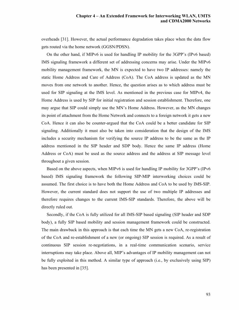
Chapter 4 – An Extended Framework for Interworking WLAN, UMTS
and CDMA2000 Networks
93
overheads [31]. However, the actual performance degradation takes place when the data flow
gets routed via the home network (GGSN/PDSN).
On the other hand, if MIPv6 is used for handling IP mobility for the 3GPP’s (IPv6 based)
IMS signaling framework a different set of addressing concerns may arise. Under the MIPv6
mobility management framework, the MN is expected to have two IP addresses: namely the
static Home Address and Care of Address (CoA). The CoA address is updated as the MN
moves from one network to another. Hence, the question arises as to which address must be
used for SIP signaling at the IMS level. As mentioned in the previous case for MIPv4, the
Home Address is used by SIP for initial registration and session establishment. Therefore, one
may argue that SIP could simply use the MN’s Home Address. However, as the MN changes
its point of attachment from the Home Network and connects to a foreign network it gets a new
CoA. Hence it can also be counter-argued that the CoA could be a better candidate for SIP
signaling. Additionally it must also be taken into consideration that the design of the IMS
includes a security mechanism for verifying the source IP address to be the same as the IP
address mentioned in the SIP header and SDP body. Hence the same IP address (Home
Address or CoA) must be used as the source address and the address at SIP message level
throughout a given session.
Based on the above aspects, when MIPv6 is used for handling IP mobility for 3GPP’s (IPv6
based) IMS signaling framework the following SIP-MIP interworking choices could be
assumed. The first choice is to have both the Home Address and CoA to be used by IMS-SIP.
However, the current standard does not support the use of two multiple IP addresses and
therefore requires changes to the current IMS-SIP standards. Therefore, the above will be
directly ruled out.
Secondly, if the CoA is fully utilized for all IMS-SIP based signaling (SIP header and SDP
body), a fully SIP based mobility and session management framework could be constructed.
The main drawback in this approach is that each time the MN gets a new CoA, re-registration
of the CoA and re-establishment of a new (or ongoing) SIP session is required. As a result of
continuous SIP session re-negotiations, in a real-time communication scenario, service
interruptions may take place. Above all, MIP’s advantages of IP mobility management can not
be fully exploited in this method. A similar type of approach (i.e., by exclusively using SIP)
has been presented in [35].
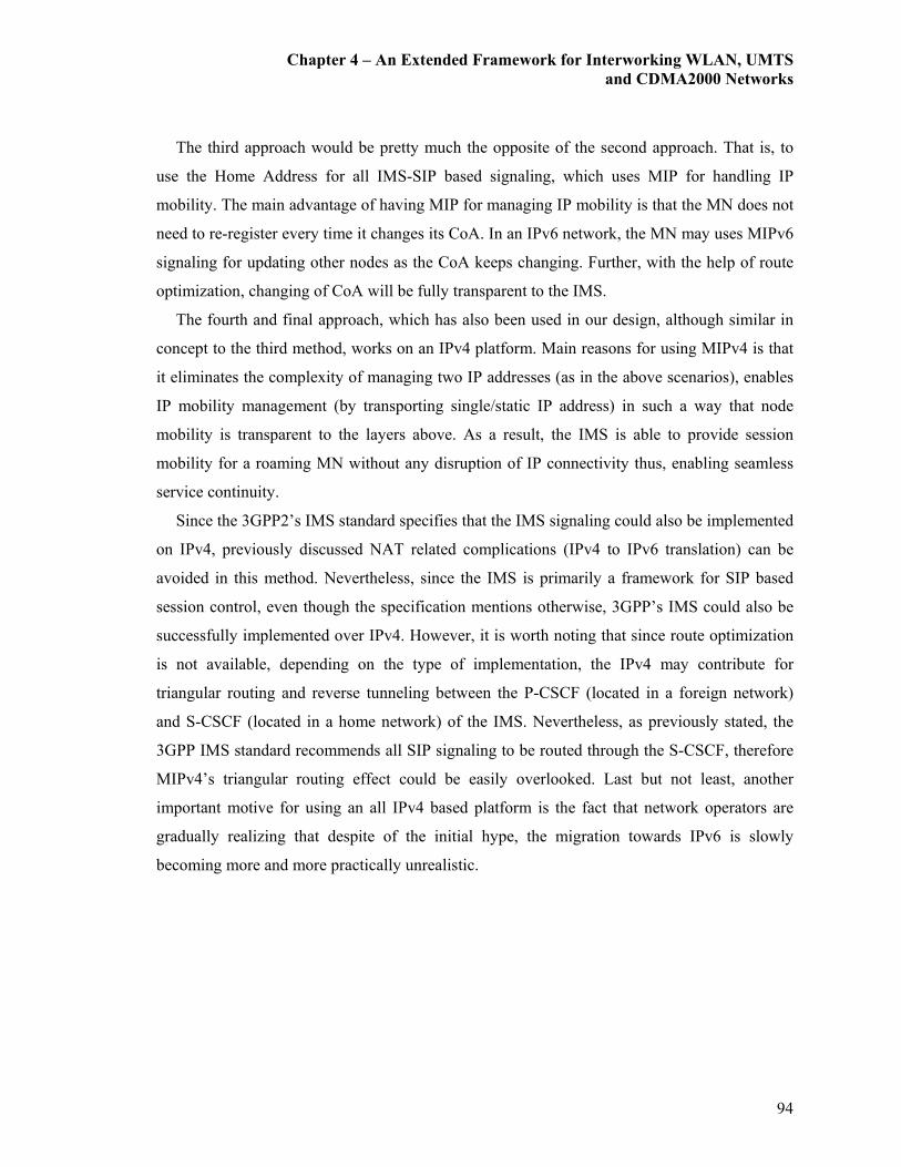
Chapter 4 – An Extended Framework for Interworking WLAN, UMTS
and CDMA2000 Networks
94
The third approach would be pretty much the opposite of the second approach. That is, to
use the Home Address for all IMS-SIP based signaling, which uses MIP for handling IP
mobility. The main advantage of having MIP for managing IP mobility is that the MN does not
need to re-register every time it changes its CoA. In an IPv6 network, the MN may uses MIPv6
signaling for updating other nodes as the CoA keeps changing. Further, with the help of route
optimization, changing of CoA will be fully transparent to the IMS.
The fourth and final approach, which has also been used in our design, although similar in
concept to the third method, works on an IPv4 platform. Main reasons for using MIPv4 is that
it eliminates the complexity of managing two IP addresses (as in the above scenarios), enables
IP mobility management (by transporting single/static IP address) in such a way that node
mobility is transparent to the layers above. As a result, the IMS is able to provide session
mobility for a roaming MN without any disruption of IP connectivity thus, enabling seamless
service continuity.
Since the 3GPP2’s IMS standard specifies that the IMS signaling could also be implemented
on IPv4, previously discussed NAT related complications (IPv4 to IPv6 translation) can be
avoided in this method. Nevertheless, since the IMS is primarily a framework for SIP based
session control, even though the specification mentions otherwise, 3GPP’s IMS could also be
successfully implemented over IPv4. However, it is worth noting that since route optimization
is not available, depending on the type of implementation, the IPv4 may contribute for
triangular routing and reverse tunneling between the P-CSCF (located in a foreign network)
and S-CSCF (located in a home network) of the IMS. Nevertheless, as previously stated, the
3GPP IMS standard recommends all SIP signaling to be routed through the S-CSCF, therefore
MIPv4’s triangular routing effect could be easily overlooked. Last but not least, another
important motive for using an all IPv4 based platform is the fact that network operators are
gradually realizing that despite of the initial hype, the migration towards IPv6 is slowly
becoming more and more practically unrealistic.

Chapter 4 – An Extended Framework for Interworking WLAN, UMTS
and CDMA2000 Networks
95
4.4 The Interworking Architecture
The proposed extended internetworking architecture, with signaling and data routes, is
illustrated in Fig. 4.1 [40]. Based on the existing UMTS and CDMA2000 mobility
management mechanisms, this architecture proposes a framework for the NGMN’s for
providing real-time IP multimedia services.
As per the illustration on Fig. 4.1, the UMTS core network is connected to the IP network
through the GGSN, which also acts as its MIPv4 FA. Prior to acquiring the IP address, the MN
goes through the following steps. The first step involves with the MN powering on and locking
to the UMTS network. Once the appropriate cell is selected the MN can be considered ready
for the establishment of a data session. It is assumed that this function is already performed by
the MN, and will not be discussed in detail.
Once the above mentioned system acquisition is done, the next step is to establish a data
connection, or set up a data pipeline. This must be completed in two steps by using the Attach
and PDP context activation message sequences. The activation of the MN’s PDP context does
not allocate an IP address and the IP address field of the PDP context is not filled at this point.
The actual IP address allocation for the MN is initiated by sending the MIPv4 registration
requests to it’s HA via the GGSN (MIP-FA). This mechanism is based on the specifications
given under 3GPP’s [186].
This is triggered when the MN receives a periodically broadcasted agent advertisement sent
by the GGSN (MIP-FA). When the MN receives this message it sends a MIP Registration
Request message to the GGSN (MIP-FA). The GGSN (MIP-FA) forwards this request to the
MIP-HA and the HA assigns the home IP address to the MN via a MIP Registration Reply
message. Further, the HA maintains the MS’s location information such as the GGSN (MIP-
FA) address. When the GGSN (MIP-FA) receives this information the MN gets its home IP
address assigned.
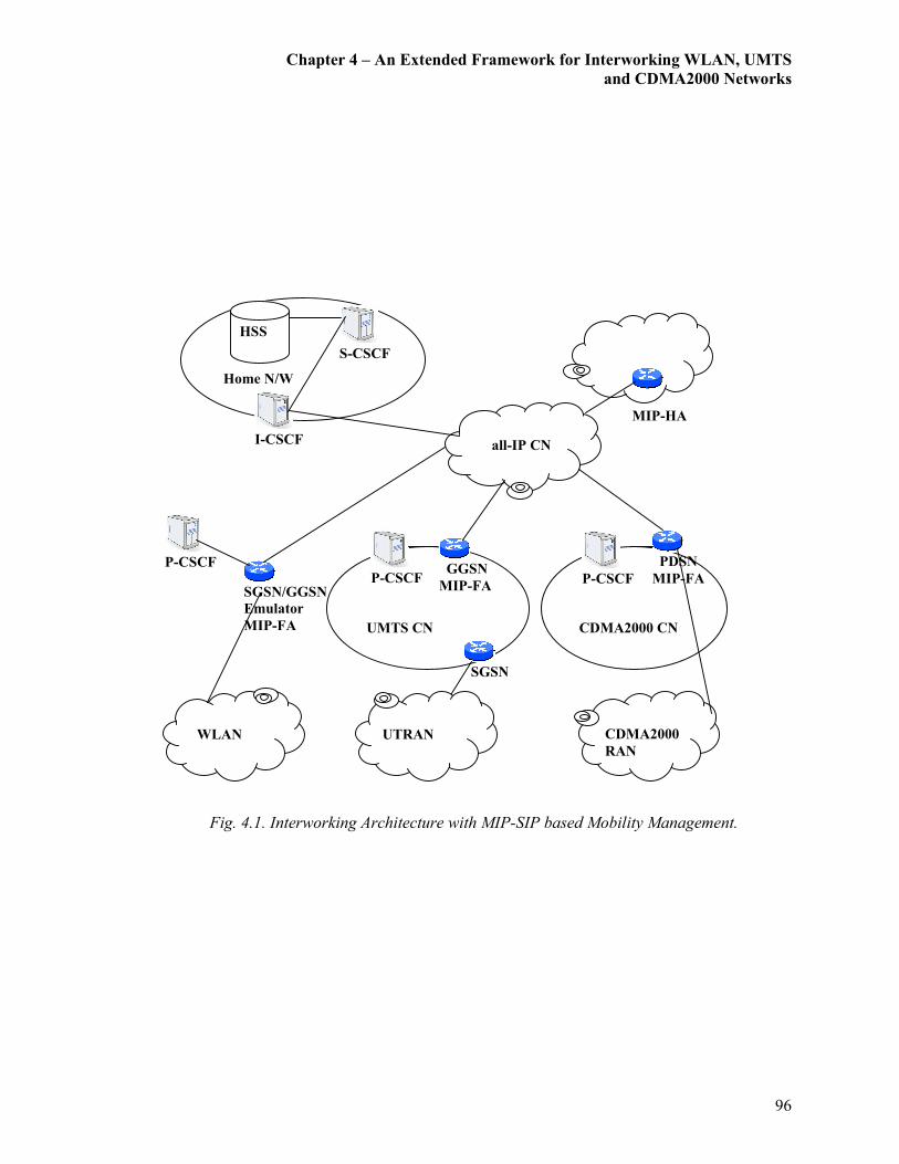
Chapter 4 – An Extended Framework for Interworking WLAN, UMTS
and CDMA2000 Networks
96
Fig. 4.1. Interworking Architecture with MIP-SIP based Mobility Management.
Home N/W
SGSN/GGSN
Emulator
MIP-FA
P-CSCF
WLAN
CDMA2000
RAN
UMTS CN
SGSN
GGSN
MIP-FA
CDMA2000 CN
PDSN
MIP-FA
MIP-HA
S-CSCF
HSS
P-CSCF
P-CSCF
UTRAN
I-CSCF
all-IP CN
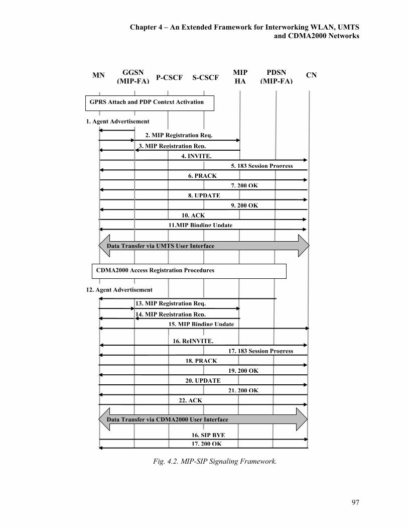
Chapter 4 – An Extended Framework for Interworking WLAN, UMTS
and CDMA2000 Networks
97
Fig. 4.2. MIP-SIP Signaling Framework.
15. MIP Binding Update
14. MIP Registration Rep.
13. MIP Registration Req.
11.MIP Binding Update
4. INVITE.
10. ACK
9. 200 OK
8. UPDATE
5. 183 Session Progress
7. 200 OK
3. MIP Registration Rep.
6. PRACK
MN P-CSCF S-CSCF CN
Data Transfer via UMTS User Interface
GPRS Attach and PDP Context Activation
GGSN
(MIP-FA)
PDSN
(MIP-FA)
MIP
HA
1. Agent Advertisement
2. MIP Registration Req.
CDMA2000 Access Registration Procedures
12. Agent Advertisement
Data Transfer via CDMA2000 User Interface
17. 200 OK
16. SIP BYE
16. ReINVITE.
22. ACK
21. 200 OK
20. UPDATE
17. 183 Session Progress
19. 200 OK
18. PRACK

Chapter 4 – An Extended Framework for Interworking WLAN, UMTS
and CDMA2000 Networks
98
Now the MN is able to identify the P-CSCF for the registration with the IMS. Prior to
establishing a SIP session, the MN requires performing a service registration function to let the
IMS know of its location. The MN acts as a SIP client and sends a SIP registration message to
its home system through the P-CSCF. The basic steps for a SIP service registration can be
summarized as follows. Firstly, the HSS for the MN is notified of its current location for the
HSS to update the subscriber profile accordingly. Next the HSS checks if the MN is allowed to
register in the network based on the subscriber profile and operator limitations, and grants
authorization. Once authorized, a suitable S-CSCF for the MN is assigned and its subscriber
profile is sent to the designated S-CSCF.
After the activation of the PDP context and the service registration, the MN is ready to
establish a media/data/call session. As illustrated in Fig. 4.2, the sequence of the SIP session
origination procedure can be described as follows. The mobile origination procedure is initiated
by a SIP INVITE message sent form the UMTS interface of the source MN. This initial
message is forwarded from the P-CSCF to the S-CSCF of the originating network, via the
CSCFs of the terminating network, and finally to the destination. This SIP INVITE request
carries a SDP body indicating the IP address and port numbers where the source wants to
receive the media streams. Furthermore, the INVITE also contains a request to follow the
precondition call flow model. This is important because some clients require certain
preconditions (that is, QoS levels) to be met before establishing a session. The requirement for
using the preconditions call flow model in the IMS is mainly because in cellular networks radio
resources for the media plane are not always available. If the preconditions extension was not
used, when the called party accepts the call, the source and destination may not be ready and
consequently the first few packets may be lost.
Next, this model requires that the destination responds with a 183 Session Progress message
containing a SDP answer. The SDP answer contains the media streams and codecs that the
destination is able to accept for this session. The acknowledgement for the reception of this
provisional response by a PRACK request follows afterwards. If the destination does not
receive a PRACK response within a determined time, it will transmit the provisional response.
When the PRACK request successfully reaches the destination a 200 OK response is generated
by the destination with an SDP answer. Next an UPDATE request is sent by the source
containing another SDP offer, in which the source indicates that the resources are reserved at

Chapter 4 – An Extended Framework for Interworking WLAN, UMTS
and CDMA2000 Networks
99
its local segment. Once the destination receives the UPDATE request, it generates a 200 OK
response. Once this is done, the MN can start the media/data flow and the session will be in
progress (via the UMTS interface).
When this MN roams between CDMA2000 and UMTS systems inter-system roaming takes
place. The message flow for an inter-system roaming from UMTS to CDMA2000 can be
described as follows. Firstly the standard CDMA2000 link layer access registration procedures
are performed. Next the CDMA2000 interface performs the MIP registration procedures with
the PDSN (i.e., MIP FA) as explained previously. This is when the PDSN forwards this request
to the MIP-HA and the HA assigns the home IP address to the new CDMA2000 interface.
Lastly the exchanging of a MIP Binding Update (BU) message between the MN and the
corresponding node for avoiding triangular routing [125].
The next stage is the taking place of the IMS-SIP session handoff procedures. This requires
sending a SIP ReINVITE (with the same Call-ID and other identifiers corresponding to the
ongoing session) to the destination SIP UAC. Followed by this is a resource/preconditions
reservation for the CDMA2000 interface. Once this is successfully done the new session flow
can be initiated. It is important to note that until such time that the new data flow is initiated via
the CDMA2000 interface, the data flow via the UMTS interface remains active. Thus the
model follows the make-before-break handoff mechanism as proposed in our previous works
[35]. Finally, the UMTS interface performs the implicit detach procedures with the SGSN and
the PDP context is deactivated. Inter-system roaming form CDMA2000 to UMTS can also take
place in a similar manner.
Furthermore, since this design is an extension to the UMTS-WLAN interworking platform
proposed in Chapter 3, this extended architecture could be considered as a generalized
framework for roaming between WLAN-UMTS-CDMA2000 networks. The introduction of
MIP, unlike the Pure-SIP based approach, helps to reduce extra application layer based
signaling, thus enabling a smoother vertical handoff. The next sections will be essentially
investigating and reporting the performance comparisons between these two vertical handoff
approaches.
Chapter 4 – An Extended Framework for Interworking WLAN, UMTS
and CDMA2000 Networks
100
4.5 Analytical Modeling
This section provides an analytically modeled approach for evaluating the newly proposed
extended version of the interworking architecture. The primary aim of this analytical model is
to help compare the benefit of introducing MIP for terminal mobility management (below an
IMS based session mobility management framework) in contrast to having terminal and session
mobility management purely handled by the IMS.
This analysis uses a similar approach, as explained in Section 3.5, for evaluating QoS
metrics and measures involved in the above MIP and SIP combined mobility management
approach. QoS metrics such as reconfiguration and vertical handoff delay (from the network
layer and above), total packet loss, jitter, and signaling overhead are analyzed under this
section and compared against the results obtained for a Pure-SIP based scenario. Since the aim
of this thesis is to develop a universal mobility management platform by having the IMS as a
common arbitrator, delay components relating to the Physical and Link Layers of various
wireless networks/links (i.e., UMTS, CDMA2000, WLAN, and so on) has been overlooked.
Furthermore, for the purpose of easy understanding and comparison against the results of
Chapter 3, a MIP-SIP based UMTS-WLAN interworking scenario has been considered (rather
than having a UMTS-CDMA2000 interworking scenario).
This analysis is also based on a similar assumption as in Section 3.5, that the call/session
arrivals follow a Poisson process. Furthermore, it can be stated that the arguments provided in
Section 3.5 for justifying VoIP session arrivals to be modeled as a Poisson process will also be
similarly applicable.
4.5.1 Handoff Delay
In this section, the derived formula under Section 3.5.1 will be appropriately modified for a
comparative analysis of the vertical session handoff delay for the newly proposed MIP-SIP
based architecture illustrated in Fig. 4.1. A modified analysis method is used for comparing the
efficiency of the new MIP-SIP based vertical session handoff mechanism (i.e., delay, in this
case) against the previously presented Pure-SIP based session handoff mechanism, for a data
session establishment.

Chapter 4 – An Extended Framework for Interworking WLAN, UMTS
and CDMA2000 Networks
101
Similar to the approach used under Section 3.5.1, the vertical handoff sub-procedural delays
such as the Link Layer handoff delay, movement detection delay, and packet re-transmission
delay have not been taken into consideration. Additionally, according to the proposed
enhancements to the architecture for an SIP-MIP based vertical handoff (as illustrated in Fig.
4.2), there is no DHCP based address allocation delay. Thus the main contributor to the
Network Layer based vertical handoff delay is the session re-configuration delay. Therefore, it
can be expressed that the new vertical session handoff delay (at the core network level
regardless of the underlying radio network and Link Layer delays) for the newly considered
scenario mainly consists of the (previously considered) IMS based session handoff delay at the
Application Layer and the newly introduced MIP related delay at the Network Layer. Another
reason for the exclusion of the above mentioned delay components is that, these delay
components may significantly vary depending on the radio network technology used, and thus
not being able to provide a fair evaluation of the performance of the interworking architecture.
In order to derive an expression for the vertical handoff delay for a MIP-SIP combined
method, equation (3.5) will be used. As mentioned under Section 3.1, equation 3.5 expresses
the end-to-end transmission delay for a packet size S, sent from network A to network B over a
number of hops via a wireless and wired links. This has been directly applied to the entire MIP
and IMS SIP signaling flow involved in the vertical handoff mechanism illustrated in Fig. 4.2.
Therefore, the final expression in this case (i.e., a MIP and SIP combined handoff approach),
can be expressed as a combination of the following end-to-end delay components as expressed
in equation (4.1).
DMIP-SIP = D(SMIPReq, HUMTS-MIP-HA) + D(SMIPRep, HUMTS-MIP-HA) + D(SMIP-BU, HUMTS-CN)
+ D(SReINVITE, HWLAN-CN) + D(S183-SP, HWLAN-CN) + D(SPRACK, HWLAN-CN)
+ D(SOK, HWLAN-CN) + D(SUPDATE, HWLAN-CN) + D(SOK, HWLAN-CN)
+ D(SACK, HWLAN-CN) + D(SBYE, HUMTS-CN) + D(SOK, HCN-UMTS) + ∆ (4.1)
where, ∆ is additional IMS (application layer) latency. Thus equation (4.1) is capable of
providing the total vertical session handoff delay for a MIP and SIP combined scenario.
Although this particular scenario concentrates on a vertical handoff from UMTS-to-WLAN,

Chapter 4 – An Extended Framework for Interworking WLAN, UMTS
and CDMA2000 Networks
102
other vertical handoff scenarios relating to different radio interfaces such as WLAN-to-UMTS,
UMTS-to-CDMA2000, CDMA2000-to-UMTS could also be constructed with appropriate
substitutions using equation (3.5). As mentioned under Section, 3.5.1, the important point to
note here is that since it has been assumed that the channel is error free during the vertical
handoff, the likelihood of the occurrence of errors has been overlooked. This is since for
successful session establishment the entire message flow must take place and if any message is
damaged or lost the vertical handoff process will fail.
4.5.2 Packet Loss
The total packet loss during a MIP-SIP based vertical session handoff is also analyzed similarly
to Section 3.5.2. Thus, the total packet loss (LossMIP-SIP) during a MIP-SIP combined vertical
session handoff can be similarly defined as the sum of all lost packets during the vertical
handoff while the MN is receiving the downlink data packets. It is assumed that the packet loss
begins when the Layer 2 handoff is detected and all in-flight packets are lost during the vertical
handoff time. Thus, it can be expressed as:
mdSIPMIP
ad
SIPMIP NDT
Loss ××
+= −− λ
2
1 (4.2)
where, Tad is the time interval between P-CSCF discovery times, λd is the downlink packet
arrival rate at the wireless interface (this depends on the used voice codec), and Nm is the
average number of vertical handoffs during a single session [154].
4.5.3 Signaling Overhead/Cost
This section presents a comparative analysis of the signaling cost between a Pure SIP based
vertical handoff scenario and a MIP-SIP based vertical handoff scenario. Similar to the
description used under Section 3.5.3, signaling cost or overhead is defined as the accumulative
traffic load on exchanging signaling messages during the MN’s communication session (i.e.,

Chapter 4 – An Extended Framework for Interworking WLAN, UMTS
and CDMA2000 Networks
103
session establishment, session handoff, and so on). Therefore, similar to equation (3.8), the
above definition can be expressed as:
BAmessage HSPCost −××= (4.3)
where, P defines the probability associated with the occurrence of a particular event, Smessage is
the average size of a signaling message/packet related to this event, HA-B is the average number
of hops/distance the signaling packet traverses between the source node A to the destination
node B. Using the above definition and a mobility scenario similar to the illustration in Fig.
3.10, an expression for signaling cost is derived for a MIP-SIP based scenario.
Now, the signaling cost for the described MIP-SIP based vertical handoff scenario
illustrated in Fig. 4.2, can be expressed as the sum of the following two signaling components.
The first component of signaling cost computation is associated with the entire MIP and SIP
INVITE (session establishment) message sequence. As mentioned under Section 3.3, the
computation of this signaling cost component is associated with P1, which is the arrival
probability of a session to a MN that is likely to be subjected to a vertical handoff. The second
component of signaling cost computation is associated with the MIP and SIP ReINVITE
(vertical handoff) message sequence. Similar to what has been mentioned under Section 3.3,
the MIP and SIP ReINVITE sequence is associated with P2, which is the vertical handoff
probability and the inter-network mobility rate. Detailed steps for the derivation for P1 and P2
have been omitted from this section and the reader is referred to Section 3.5.3 for the same.
The total signaling overhead incurred by vertical handoffs during a given data session can be
expressed as:
( ) ( )∑∑=
−
=
− ×+×=21
1
)(Re2
1
)(1
n
i
BAINVITE
n
i
BAINVITE iiiiHSPHSPCost ηλ (4.4)
where, λ calls/min is the average session arrival rate, η min-1 is the average network mobility
rate associated with a roaming MN, n1 and n2 represent the number of messages involved in
each handoff/message exchange sequence as illustrated in Fig. 4.2. If η is the average network

Chapter 4 – An Extended Framework for Interworking WLAN, UMTS
and CDMA2000 Networks
104
mobility rate of a MN and λ is the average session arrival rate, λ/η may be defined as CMR
[164]. Thus equation (4.4) can be re-arranged as:
( ) ( )∑∑=
−
=− ×+
×=
21
1
)(Re2
1
)(1
n
i
BAINVITE
n
i
BAINVITE iiiiHSPHSPCost η
η
λη (4.5)
( ) ( )∑∑=
−
=− ×+
×=
21
1
)(Re2
1
)(1
n
i
BAINVITE
n
i
BAINVITE iiiiHSPCMRHSPCost ηη (4.6)
4.6 Performance Analysis
The following numerical results are generated using MIPv4 and 3GPP-SIP messages. Table 4.1
shows the typical SIP message sizes and other related parameters. IMS-SIP values are based on
[166]. Parameters relating to MIP and other values have been partially obtained from [154] and
[164] to maintain the consistency. The relative distances in hops are illustrated in Fig. 4.3.
Although Fig. 4.3 has a close resemblance and similar hop counts to Fig. 3.11, the inclusion of
the MIP HA and the MIP FAs at the visiting UMTS GGSN and the WLAN’s SGSN Emulator
makes it possible to account for the hop counts related to MIP related signaling.
Based on the values of Table IV.I and Fig. 4.3, the following analytical results are derived
for equations (4.1), (4.2), (4.4) and (4.6) for the scenario of a MIP-SIP based vertical handoff.
Fig. 4.4 and 4.5 illustrate the behavior of vertical handoff delay against increasing session
handoffs for UMTS-to-WLAN and WLAN-to-UMTS interfaces respectively. The graphs in
Fig. 4.5 indicate relatively higher vertical handoff delays for the WLAN-to-UMTS case. On the
other hand, the two graphs in Fig. 4.4 indicate a relatively lower handoff delay for the UMTS-
to-WLAN case. This indicates that when a session is transferred to a network with relatively
lower link bandwidth, a relatively higher vertical handoff delay can be expected.
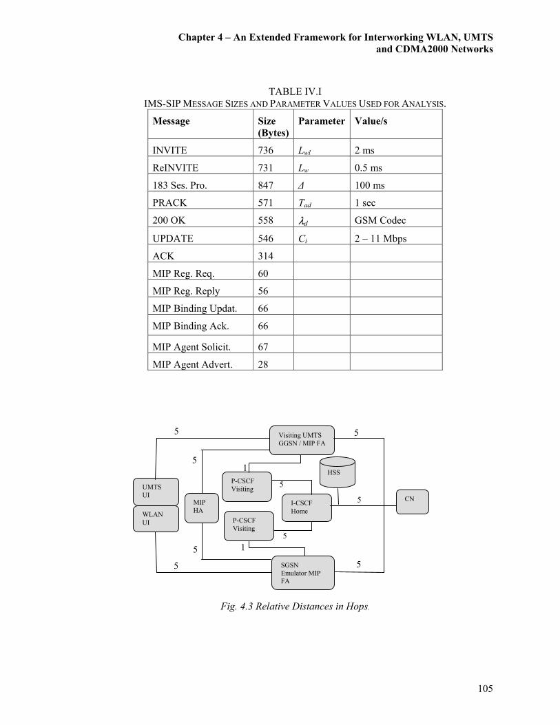
Chapter 4 – An Extended Framework for Interworking WLAN, UMTS
and CDMA2000 Networks
105
TABLE IV.I
IMS-SIP MESSAGE SIZES AND PARAMETER VALUES USED FOR ANALYSIS.
Message Size
(Bytes)
Parameter Value/s
INVITE 736 Lwl 2 ms
ReINVITE 731 Lw 0.5 ms
183 Ses. Pro. 847 ∆ 100 ms
PRACK 571 Tad 1 sec
200 OK 558 λd GSM Codec
UPDATE 546 Ci 2 – 11 Mbps
ACK 314
MIP Reg. Req. 60
MIP Reg. Reply 56
MIP Binding Updat. 66
MIP Binding Ack. 66
MIP Agent Solicit. 67
MIP Agent Advert. 28
Fig. 4.3 Relative Distances in Hops.
1
1 5
5
5
5
5
5
5
5
5
UMTS
UI
Visiting UMTS
GGSN / MIP FA
P-CSCF
Visiting
WLAN
UI
I-CSCF
Home
SGSN
Emulator MIP
FA
CN
HSS
P-CSCF
Visiting
MIP
HA

Chapter 4 – An Extended Framework for Interworking WLAN, UMTS
and CDMA2000 Networks
106
According to the results of the presented analytical model, for a MIP-SIP combined
mechanism, the average session establishment delay over the UMTS and WLAN interfaces are
192 ms and 176 ms, respectively. On the other hand, according to Section 3.6, for a Pure-SIP
based mechanism (purely based on IMS related mobility management), the average session
establishment delay over the UMTS and WLAN interfaces are 170 ms and 155 ms,
respectively. The reason behind the relatively higher session establishment delay for the MIP-
SIP combined approach is the additional MIP related messages such as MIP Registrations and
MIP BUs (refer Fig. 4.2). However, the effects of the IMS (i.e., message flows and additional
latencies) could be treated as equivalent in these scenarios.
Next, the average vertical handoff delays based on the MIP-SIP mechanism for WLAN-to-
UMTS and UMTS-to-WLAN are 192 ms and 176 ms, respectively. Similarly, according to
Section 3.6, the corresponding values for the average vertical handoff delays based on the
Pure-SIP mechanism for WLAN-to-UMTS and UMTS-to-WLAN are 210 ms and 186 ms,
respectively. On the contrary to the observation relating to session establishment, the vertical
handoff delay for a MIP-SIP combined mechanism is relatively lower than for a Pure-SIP
based method. This could be easily clarified by referring to Fig. 3.2 and Fig. 4.2. According to
these figures, it is clear that the Pure-SIP method is fully involved with heavy IMS based
vertical handoff signaling in comparison to the MIP-SIP combined vertical handoff method,
which is partly based on the IMS and partly based on MIP. Therefore, the additional latency
involved with the IMS based SIP REFER method contributes to the increase in the vertical
handoff delay in this case.
Another important observation is that both the session establishment delay and session
handoff delay in the case of the MIP-SIP combined method are the same. According to the
MIP-SIP signaling framework illustrated in Fig. 4.2, it can be said that all MIP session
establishment procedures outside its home network (i.e., the MIP HA in this case) are treated as
a case of potential MIP handoff. Thus similar signaling (i.e., MIP Registration and MIP BU)
messages are used. Similarly, for the case of the IMS based session handoff procedures, the
SIP ReINVITE method is used, which also has a similar message flow to the SIP INVITE
method. Hence identical session establishment and handoff delays are experienced under a
MIP-SIP combined method.
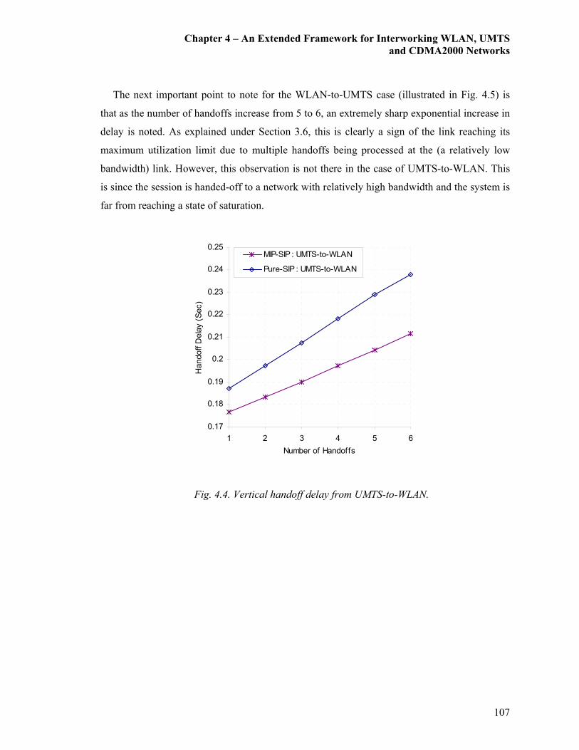
Chapter 4 – An Extended Framework for Interworking WLAN, UMTS
and CDMA2000 Networks
107
The next important point to note for the WLAN-to-UMTS case (illustrated in Fig. 4.5) is
that as the number of handoffs increase from 5 to 6, an extremely sharp exponential increase in
delay is noted. As explained under Section 3.6, this is clearly a sign of the link reaching its
maximum utilization limit due to multiple handoffs being processed at the (a relatively low
bandwidth) link. However, this observation is not there in the case of UMTS-to-WLAN. This
is since the session is handed-off to a network with relatively high bandwidth and the system is
far from reaching a state of saturation.
0.17
0.18
0.19
0.2
0.21
0.22
0.23
0.24
0.25
1 2 3 4 5 6
Number of Handoffs
Handoff Delay (Sec)
MIP-SIP : UMTS-to-WLAN
Pure-SIP : UMTS-to-WLAN
Fig. 4.4. Vertical handoff delay from UMTS-to-WLAN.

Chapter 4 – An Extended Framework for Interworking WLAN, UMTS
and CDMA2000 Networks
108
0.15
0.35
0.55
0.75
0.95
1.15
1.35
1 2 3 4 5 6
Number of Handoffs
Handoff D
elay (Sec)
MIP-SIP : WLAN-to-UMTS
Pure-SIP : WLAN-to-UMTS
Fig. 4.5. Vertical handoff delay from WLAN-to-UMTS.
Figure 4.6 illustrates the normalized transient packet loss during vertical handoffs as the
number of handoffs increase (in the case of a break-before-make handoff scenario). The voice
codec considered for the downlink packet transmission in this case is the GSM codec.
According to equation (4.2), the packet loss during a vertical handoff is directly proportional to
the vertical handoff delay. Therefore, relatively high vertical handoff delays indicated by the
WLAN-to-UMTS graphs in Fig. 4.5 directly contribute to the exponential behavior of packet
loss as shown in Fig. 4.7. Similarly, the packet loss is relatively low in Fig. 4.6 for a UMTS-to-
WLAN handoff, which is also in line with the corresponding handoff delay shown in Fig. 4.4.
Furthermore, as expected, Pure-SIP approach shows a relatively higher packet loss in all
considered scenarios in comparison to the graphs representing the MIP-SIP method. Another
notable point (although not very important) from the plots in Fig. 4.5 and Fig. 4.7 is that the
graphs diverge from one another as the packet transmission rates and the numbers of handoffs
per session increases. This is similar to the phenomenon observed in the graphs in Fig. 3.14.
As explained under Section 3.6, the reason for the divergence between the graphs is the
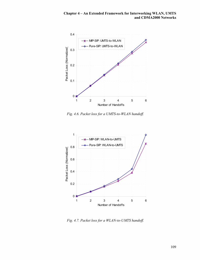
Chapter 4 – An Extended Framework for Interworking WLAN, UMTS
and CDMA2000 Networks
109
0
0.1
0.2
0.3
0.4
1 2 3 4 5 6
Number of Handoffs
Packet Loss (Norm
alized)
MIP-SIP: UMTS-to-WLAN
Pure-SIP: UMTS-to-WLAN
Fig. 4.6. Packet loss for a UMTS-to-WLAN handoff.
0
0.2
0.4
0.6
0.8
1
1 2 3 4 5 6
Number of Handoffs
Packet Loss (Norm
alized)
MIP-SIP: WLAN-to-UMTS
Pure-SIP: WLAN-to-UMTS
Fig. 4.7. Packet loss for a WLAN-to-UMTS handoff.
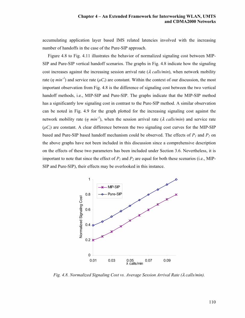
Chapter 4 – An Extended Framework for Interworking WLAN, UMTS
and CDMA2000 Networks
110
accumulating application layer based IMS related latencies involved with the increasing
number of handoffs in the case of the Pure-SIP approach.
Figure 4.8 to Fig. 4.11 illustrates the behavior of normalized signaling cost between MIP-
SIP and Pure-SIP vertical handoff scenarios. The graphs in Fig. 4.8 indicate how the signaling
cost increases against the increasing session arrival rate (λ calls/min), when network mobility
rate (η min-1) and service rate (µCi) are constant. Within the context of our discussion, the most
important observation from Fig. 4.8 is the difference of signaling cost between the two vertical
handoff methods, i.e., MIP-SIP and Pure-SIP. The graphs indicate that the MIP-SIP method
has a significantly low signaling cost in contrast to the Pure-SIP method. A similar observation
can be noted in Fig. 4.9 for the graph plotted for the increasing signaling cost against the
network mobility rate (η min-1), when the session arrival rate (λ calls/min) and service rate
(µCi) are constant. A clear difference between the two signaling cost curves for the MIP-SIP
based and Pure-SIP based handoff mechanism could be observed. The effects of P1 and P2 on
the above graphs have not been included in this discussion since a comprehensive description
on the effects of these two parameters has been included under Section 3.6. Nevertheless, it is
important to note that since the effect of P1 and P2 are equal for both these scenarios (i.e., MIP-
SIP and Pure-SIP), their effects may be overlooked in this instance.
0
0.2
0.4
0.6
0.8
1
0.01 0.03 0.05 0.07 0.09λ calls/min
Norm
alized Signaling C
ost
MIP-SIP
Pure-SIP
Fig. 4.8. Normalized Signaling Cost vs. Average Session Arrival Rate (λ calls/min).
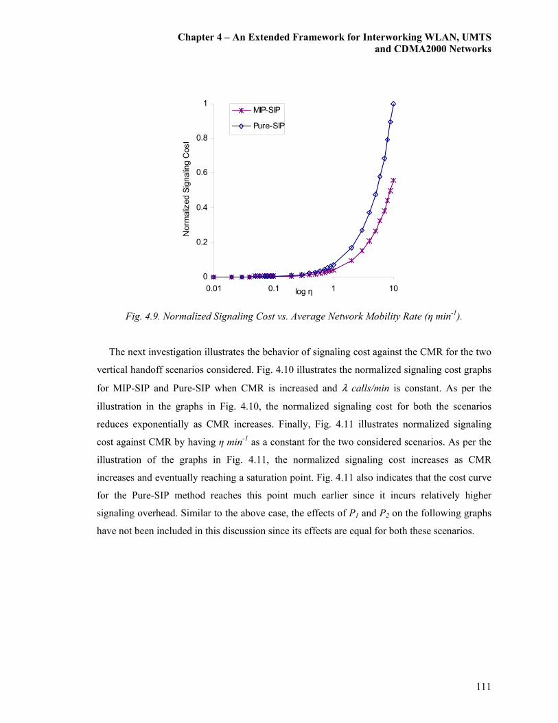
Chapter 4 – An Extended Framework for Interworking WLAN, UMTS
and CDMA2000 Networks
111
0
0.2
0.4
0.6
0.8
1
0.01 0.1 1 10log η
Norm
alized Signaling C
ost
MIP-SIP
Pure-SIP
Fig. 4.9. Normalized Signaling Cost vs. Average Network Mobility Rate (η min-1).
The next investigation illustrates the behavior of signaling cost against the CMR for the two
vertical handoff scenarios considered. Fig. 4.10 illustrates the normalized signaling cost graphs
for MIP-SIP and Pure-SIP when CMR is increased and λ calls/min is constant. As per the
illustration in the graphs in Fig. 4.10, the normalized signaling cost for both the scenarios
reduces exponentially as CMR increases. Finally, Fig. 4.11 illustrates normalized signaling
cost against CMR by having η min-1 as a constant for the two considered scenarios. As per the
illustration of the graphs in Fig. 4.11, the normalized signaling cost increases as CMR
increases and eventually reaching a saturation point. Fig. 4.11 also indicates that the cost curve
for the Pure-SIP method reaches this point much earlier since it incurs relatively higher
signaling overhead. Similar to the above case, the effects of P1 and P2 on the following graphs
have not been included in this discussion since its effects are equal for both these scenarios.
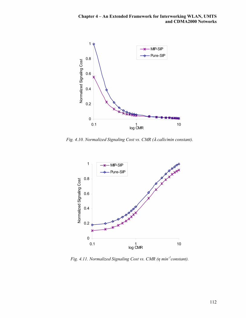
Chapter 4 – An Extended Framework for Interworking WLAN, UMTS
and CDMA2000 Networks
112
0
0.2
0.4
0.6
0.8
1
0.1 1 10log CMR
Norm
alized Signaling Cost
MIP-SIP
Pure-SIP
Fig. 4.10. Normalized Signaling Cost vs. CMR (λ calls/min constant).
0
0.2
0.4
0.6
0.8
1
0.1 1 10log CMR
Norm
alized Signaling C
ost
MIP-SIP
Pure-SIP
Fig. 4.11. Normalized Signaling Cost vs. CMR (η min-1constant).
Chapter 4 – An Extended Framework for Interworking WLAN, UMTS
and CDMA2000 Networks
113
4.7 Network Modeling and Results
In order to investigate the validity of the above described architecture, a network simulation
scenario is modeled using OPNET Modeler 11.5. Since OPNET’s standard SIP components do
not address the specifications of the IMS, substantial modifications are required for the
development of a fully functional SIP-IMS model. Our newly developed SIP-IMS model is an
enhanced version of the basic IMS-SIP signaling model, which is currently available under the
contributed models library of the OPNET University Program [138]. These modifications can
be summarized as follows: SIP UASs modified as CSCFs, IMS-SIP based messaging and flow
generation between CSCFs, introduce roaming facility between multiple domains, and facility
for introducing process delay controls (i.e. for messages sent between CSCFs and the HSS
queries). As a result, an IMS that is capable of basic SIP signaling for session management is
developed.
Next, underneath the existing IMS architecture a MIP v4 framework is constructed. The
MIP framework consists of a common HA and multiple FAs. The intention of having MIP is
for handling IP mobility at the Network Layer (and limiting the IMS exclusively for session
mobility management). Followed by this is the task of creating an all-IP based, heterogeneous
networking environment with MIP and SIP signaling as illustrated in Fig. 4.2. The simplest
way to create such an environment (within the scope of OPNET 11.5) is by interworking
between a WLAN and a UMTS core network. Since OPNET does not currently have a
specialized module for CDMA2000 networks, it has been excluded from our simulation test-
bed. Nevertheless, it can be argued that since the aim of these simulations are for validating the
potential of combining the IMS with MIP for achieving a unified mobility platform at the core
network level for an all-IP heterogeneous network, a WLAN-UMTS interworked test-bed
should essentially be sufficient.
Details of the WLAN-UMTS interworking model are as follows. As per Fig. 4.1, the
WLAN is connected via an SGSN/GGSN emulator to the all-IP core network. There are two
types of signaling taking place. The first type is the IMS-SIP signaling, which takes place via
the P-CSCFs (i.e., a SIP B2BUA) connected to each of these networks. These P-CSCFs are
then connected to the S-CSCF, the IMS node implemented in the all-IP core network. It must
also be noted that the I-CSCF is excluded in this model since it is mainly used at the time of
Chapter 4 – An Extended Framework for Interworking WLAN, UMTS
and CDMA2000 Networks
114
SIP Registration process and it is assumed that SIP registration has already taken place with the
S-CSCF. The second type of signaling is the MIP signaling. In order to enable MIP signaling in
UMTS and WLAN networks, FAs are setup at the GGSN and SGSN/GGSN emulator
respectively. These FAs will be connected to the HA in the all-IP core network for MIP
signaling.
Using the above described platform, measurements are collected for investigating a joint
SIP-MIP vertical hand-off (say, from UMTS to WLAN in this case). At this instance, the
measurements for vertical handoff are observed at the core network level and the radio network
related delays and DHCP address distribution delays are not taken into consideration. The only
delays considered are MIP registration requests, MIP binding update requests, and SIP related
signaling and processing delays. The argument for measuring vertical handoff delay at the core
network is needed to evaluate the joint SIP-MIP session and mobility management mechanism
against our previously published works (i.e., a pure IMS-SIP based session and mobility
management approach) [35]. Therefore these results may be applicable for an all-IP core
network (under similar conditions).
The simulation results for vertical handoff delay for a VoIP session obtained for the two
mobility mechanisms are as follows. The average session establishment delay for a VoIP
session based on a MIP-SIP based joint mechanism for a UMTS and a WLAN interface are
240 ms and 200 ms respectively. Also, according to Section 3.4.3, the average session
establishment delay for a VoIP session based on a Pure-SIP based joint mechanism for a
UMTS and a WLAN interface are 197 ms and 182 ms respectively. Next, the average vertical
handoff delay for a VoIP session based on a MIP-SIP based joint mechanism for a WLAN-to-
UMTS handoff and a UMTS-to-WLAN handoff are 220 ms and 196 ms, respectively. Then
again, according to Section 3.4.3, the average vertical handoff delay for a VoIP session based
on a Pure-SIP based joint mechanism for a WLAN-to-UMTS handoff and a UMTS-to-WLAN
handoff are 245 ms and 215 ms respectively.
Similar to our analytical results, the handoff delay for the MIP-SIP based architecture
reveals lower delay as compared to the MIP-SIP combined approach. Furthermore, the above
results show rather close resemblance to the analytical results presented in Section 4.6.
However, the simulation results obtained for the average session establishment delay and the
average handoff delay are approximately 12-20% higher of the analytical results. Such a degree

Chapter 4 – An Extended Framework for Interworking WLAN, UMTS
and CDMA2000 Networks
115
of variation in the simulated result is unfortunately inevitable since the system initialization
delays may affect the final outcome. The interesting point about our simulation results is that,
to a certain extent, they are inline with results published for the case of horizontal handoff
delays [164], [187]. As mentioned in the previous Chapter, a make-before-break handoff
technique must be implemented for ensuring seamless vertical handoffs as described in [35].
0
10
20
30
40
50
1 2 3 4 5 6
Number of Handoffs
Packet Loss (KBytes)
G.711: Pure-SIP G.726: Pure-SIP
GSM: Pure-SIP G.729: Pure-SIP
G.723.1: Pure-SIP G.711: MIP-SIP
G.726: MIP-SIP GSM: MIP-SIP
G.729: MIP-SIP G.723.1: MIP-SIP
Fig. 4.12. Transient packet loss comparison for UMTS-to-WLAN vertical handoff
for MIP-SIP and Pure-SIP mechanisms.
Figures 4.12 and 4.13 illustrate the transient packet loss scenarios for UMTS-to-WLAN and
WLAN-to-UMTS handoff over different codecs respectively. These results can also be seen as
an extension to the results presented in Fig. 3.8, where the performance of each codec behaves
similarly. The packet loss is observed by simulating a break-before-make type handoff as
described in detail in the previous section. According to the previous explanations, since the
Pure-SIP method incurs relatively higher vertical handoff delay, it also incurs relatively higher
transient packet loss in both the considered scenarios.

Chapter 4 – An Extended Framework for Interworking WLAN, UMTS
and CDMA2000 Networks
116
0
20
40
60
80
100
120
1 2 3 4 5 6
Number of Handoffs
Packet Loss (KBytes)
G.711: Pure-SIP
G.726: Pure-SIP
GSM: Pure-SIP
G.729: Pure-SIP
G.723.1: Pure-SIP
G.711: MIP-SIP
G.726: MIP-SIP
GSM: MIP-SIP
G.729: MIP-SIP
G.723.1: MIP-SIP
Fig. 4.13. Transient packet loss comparison for WLAN-to-UMTS vertical handoff
for MIP-SIP and Pure-SIP mechanisms.
4.8 Summary and Conclusions
This Chapter focused on extending the proposed WLAN-UMTS interworking architecture to a
unified framework for interworking dissimilar 3G cellular networking standards. As a result,
global roaming and interoperability beyond one cellular system (say, UMTS) to another
cellular system (say, CDMA2000) has become a possible reality. However, this required major
architectural changes to the initial design. As such, a coupling framework similar to the
3GPP2’s IMS was chosen. It also required re-designing of the entire mobility management
framework. Instead of having a Pure-SIP based mobility management framework, a MIP and
SIP combined mobility management framework was designed. Within this new framework,
terminal/IP mobility was managed at the network layer by MIP and session mobility was
handled by SIP at the Application Layer. The QoS analysis as well as the OPNET simulation
Chapter 4 – An Extended Framework for Interworking WLAN, UMTS
and CDMA2000 Networks
117
model indicated that a MIP-SIP based mobility management framework performed better than
its predecessor, the Pure-SIP based mobility management method. Also, the analysis results
indicated that the QoS performance for the investigated parameters were within acceptable
levels for real-time VoIP conversations. In order to claim that the proposed architecture is fully
capable of interworking with all wireless heterogeneous networks, the possibility of
interworking with BWA technologies such as a WiMAX network must also be investigated.
Therefore, the next Chapter discusses how this architecture can be further extended for
interworking with mobile WiMAX networks.

Chapter 5 – A Unified Framework for Interworking Heterogeneous
Mobile Wireless Networks
118
V{tÑàxÜ H A Unified Framework for Interworking Heterogeneous
Mobile Wireless Networks
This Chapter further extends the proposed interworking architecture into a unified mobility and
session management framework for interworking heterogeneous mobile and wireless networks.
More specifically, this Chapter introduces interworking BWA networks (such as WiMAX)
with the (previously proposed) existing platform. Therefore, the proposed platform will not
only be capable of providing global roaming between multiple cellular systems, but also will
be able to successfully interwork with 3G Cellular, WLAN, and WiMAX networks, thus
creating a truly seamless inter-network roaming experience for the user. This Chapter is
organized as follows: The next section establishes the importance for WiMAX networks to
interwork with the existing 3G cellular networks. Followed by this comes the section which
introduces the network architectures of Mobile WiMAX networks. Subsequently follows a
brief discussion on the relevant work done in the area of interworking with other networks.
Next the section on the proposed architecture, which describes how the IMS has been used as a
universal coupling mediator for internetworking, is presented. Followed by this is the section is
on the analytical modeling and the OPNET based simulation framework with relevant
performance results prior to the final conclusions. The extended interworking architecture and
the analytical model presented in this Chapter has contributed to [43] and the OPNET
simulation results have partly contributed to [44].
5.1 Introduction
WiMAX is the BWA technology primarily designed for WMANs [188]. The IEEE 802.16
specifies a fixed WMAN protocol for providing a wireless alternative for last mile broadband
access [14]. In December 2005, the IEEE ratified the 802.16e-2005 amendment to the IEEE
802.16 standard [15]. This amendment adds features and attributes to the standard to support
nomadic mobility.
Chapter 5 – A Unified Framework for Interworking Heterogeneous
Mobile Wireless Networks
119
Unfortunately, the emerging popularity of this BWA technology, commercially known as
Mobile WiMAX, was soon envisioned as a potential challenge to the long-term viability of
existing wireless technologies, including IEEE 802.11-based WLANs, broadband residential
Internet technologies such as Digital Subscriber Line (DSL) and cable, and the 3G cellular
technologies [189]. Due to Mobile WiMAX technology’s capabilities for reaching relatively
high data rates (up to 15 Mbps) and spanning over a larger coverage area (up to 4 km) with
mobility support, concerns were raised if this would become a cheaper (or perhaps a better)
alternative to the existing 3G cellular technology (i.e., voice and narrowband data) [190]. This
has resulted into a much intense competition between the fixed wireless/wired network service
providers and cellular network operators to stake their claim in the rapidly growing wireless
broadband market.
On the other hand, from a cooperative perspective, this may be treated as a powerful
complimentary technology and an opportunity towards the evolution of 4G networks by
interworking 3G cellular systems with fixed or mobile wireless access networks [191].
Therefore, a case for developing a platform for interworking between WiMAX and 3G cellular
systems may be argued as follows. To begin with, mobile WiMAX technology is still in its
infancy with many existing technical challenges [192]. Furthermore, the main hindrance to its
competitive edge (over the 3G cellular system) is the lack of a fully defined networking
infrastructure in the current mobile WiMAX standard [193]. Therefore, it may be assumed that
the mobile WiMAX technology is insufficiently equipped to be a head-to-head competitor
against the 3G network [194]. However, if it is interworked with the already well established
3G cellular networks such as UMTS or CDMA2000, it is probable that WiMAX will form an
important part of the future 4G network [84], [110]. Thus the motivation for the works
presented in this Chapter.
In the previous Chapters (Chapter 3 and Chapter 4), a novel approach towards realizing a
unified mobility and session management platform at the core network level has been proposed
[40]. This framework provides a common platform for interworking between UMTS,
CDMA2000, and WLANs. Therefore, this Chapter further extends the existing platform for
interworking with a WiMAX network. The novelty of this approach for WiMAX-UMTS-
CDMA2000-WLAN interworking is that it uses the IMS as an arbitrator for real-time session
negotiation and management as initially proposed in [35]. Furthermore, it may now be
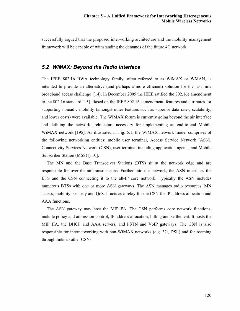
Chapter 5 – A Unified Framework for Interworking Heterogeneous
Mobile Wireless Networks
120
successfully argued that the proposed interworking architecture and the mobility management
framework will be capable of withstanding the demands of the future 4G network.
5.2 WiMAX: Beyond the Radio Interface
The IEEE 802.16 BWA technology family, often referred to as WiMAX or WMAN, is
intended to provide an alternative (and perhaps a more efficient) solution for the last mile
broadband access challenge [14]. In December 2005 the IEEE ratified the 802.16e amendment
to the 802.16 standard [15]. Based on the IEEE 802.16e amendment, features and attributes for
supporting nomadic mobility (amongst other features such as superior data rates, scalability,
and lower costs) were available. The WiMAX forum is currently going beyond the air interface
and defining the network architecture necessary for implementing an end-to-end Mobile
WiMAX network [195]. As illustrated in Fig. 5.1, the WiMAX network model comprises of
the following networking entities: mobile user terminal, Access Service Network (ASN),
Connectivity Services Network (CSN), user terminal including application agents, and Mobile
Subscriber Station (MSS) [110].
The MN and the Base Transceiver Stations (BTS) sit at the network edge and are
responsible for over-the-air transmissions. Further into the network, the ASN interfaces the
BTS and the CSN connecting it to the all-IP core network. Typically the ASN includes
numerous BTSs with one or more ASN gateways. The ASN manages radio resources, MN
access, mobility, security and QoS. It acts as a relay for the CSN for IP address allocation and
AAA functions.
The ASN gateway may host the MIP FA. The CSN performs core network functions,
include policy and admission control, IP address allocation, billing and settlement. It hosts the
MIP HA, the DHCP and AAA servers, and PSTN and VoIP gateways. The CSN is also
responsible for internetworking with non-WiMAX networks (e.g. 3G, DSL) and for roaming
through links to other CSNs.

Chapter 5 – A Unified Framework for Interworking Heterogeneous
Mobile Wireless Networks
121
Fig. 5.1. WiMAX Network Architecture.
Specifications are being developed by the Network Working Group (NWG) within the
WiMAX Forum for defining the role of the ASN and CSN and ensuring that WiMAX
networks can interwork with other networks, using WiMAX or other wireless or wired access
technologies.
In addition, the NWG specifications are designed to enable network operators to enjoy the
benefits of vendor interoperability at the infrastructure level, to rely on a consistent client
interface and, if they desire, to open their network to virtual operators, akin to existing cellular
Mobile Virtual Network Operators (MVNOs) [196]. A detailed discussion on the WiMAX
architecture is not included since it is beyond the scope of this thesis.
Chapter 5 – A Unified Framework for Interworking Heterogeneous
Mobile Wireless Networks
122
5.3 Related Work
With the above motivations, there have been some recent attempts for interworking WiMAX
with the 3G cellular networks. The initial works concentrated on different flavors of the
commonly known loose and tight coupling architectures [84]. Furthermore, throughout the past
years there have been a series of proposals about different mobility management mechanisms
as discussed subsequently.
In the case of WiMAX, MIP based approaches for mobility management have been the most
widely proposed [85]. Although MIP is recognized as a simple but effective solution for
mobility in mobile WiMAX networks in general, it suffers from several drawbacks [57].
Firstly, since it is a purely network layer oriented solution; it is unable to solve any Link Layer
handoff problems. Secondly, triangular routing may result in extended delays. Thirdly, it may
not deal with vertical handoffs due to discrepancies in the mobility management techniques of
a heterogeneous networking environment (e.g., UMTS core network does not use MIP).
One way of avoiding the above drawbacks is by adopting our previously proposed unified
coupling framework for heterogeneous networks [35]. This framework provides a MN the
highest possible level of internetworking, with fully seamless continuity of service across
heterogeneous networks. As an arbitrator for internetworking between the BWA technology
(WiMAX in this case) and the 3G Cellular network (either UMTS or CDMA2000), the IMS is
deployed. A clear advantage of using the IMS is its ability for real-time session negotiation and
management using SIP.
Nevertheless, MIP also plays an important role for IP (terminal) mobility management in
our approach. Although a similar idea of using the IMS as a coupling medium (only for session
mobility management) has been recently published at a much later stage in [110], it mainly
focuses on the QoS guarantee and the AAA aspects provided by the IMS. Most importantly the
architecture fails to sufficiently describe a mechanism for seamless vertical handoff and
mobility management. Hence, prior to introducing this novel architecture, a brief overview of
the IMS and design concepts will be presented
Chapter 5 – A Unified Framework for Interworking Heterogeneous
Mobile Wireless Networks
123
5.4 The Interworking Architecture
The extended internetworking architecture is illustrated in Fig. 5.2. The UMTS core network is
connected to the IP network through the GGSN, which also acts as its MIPv4 FA. Once the
system acquisition is done by a MN connected to the UMTS network, the next step is to set up
a data pipeline. The actual IP address allocation for the MN is initiated by sending the MIPv4
registration request to it’s HA via the GGSN (i.e., the MIP-FA). This mechanism is based on
the specifications given under [186]. The MN acts as an IMS-SIP client and sends a SIP
registration message to its home system through the P-CSCF. Once authorized, a suitable S-
CSCF for the MN is assigned and its subscriber profile is sent to the designated S-CSCF.
After the activation of the PDP context and the service registration, the MN is ready to
establish a data session. As illustrated in Fig. 5.3, the sequence of the SIP session origination
procedure can be described as follows. The mobile origination procedure is initiated by a SIP
INVITE message sent from the UMTS interface of the source MN. This initial message is
forwarded from the P-CSCF to the S-CSCF of the originating network, via the CSCFs of the
terminating network, and finally to the destination. This SIP INVITE carries a request to follow
the precondition call flow model. This is important because some clients require certain
preconditions (that is, QoS levels) to be met before establishing a session.
Once this is done, the MN can start the media/data flow and the session will be in progress
(via the UMTS interface). When this MN roams between WiMAX and UMTS systems, inter-
system roaming takes place. Generally, the selection of the appropriate network during inter-
system roaming is facilitated by an external trigger such as a network selection
mechanism/algorithm (this has not been taken into consideration since it is beyond the scope of
this thesis). Once the new network has been identified the MN undergoes relevant access
registration procedures (in this case, the WiMAX network) and AAA procedures. Next, the
vertical handoff process is initiated.
In the case of a WiMAX network, the general handoff process may either take place at layer
2 or layer 3. Layer 2 handoff, which is also known as “micro mobility,” simply changes the air
interface attachment point but keeps the IP attachment point unchanged. This process involves
the detection of signal strength, releasing the connection with the serving BS, and establishing
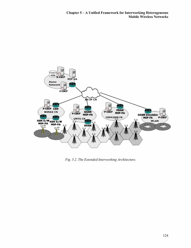
Chapter 5 – A Unified Framework for Interworking Heterogeneous
Mobile Wireless Networks
124
Fig. 5.2. The Extended Interworking Architecture.

Chapter 5 – A Unified Framework for Interworking Heterogeneous
Mobile Wireless Networks
125
Fig. 5.3. UMTS-WLAN Session Handoff Signaling.
11. MIP Binding Update
10. MIP Registration Rep.
9. MIP Registration Req.
7. MIP Binding Update
4. SIP INVITE
3. MIP Registration Rep.
MN P-CSCF S-CSCF Destination
Data Transfer via UMTS User Interface
GGSN
(MIP-FA)
ASN G/W
(MIP-FA)
MIP
HA
1. Agent Advertisement
2. MIP Registration Req.
Data Transfer via WiMAX User Interface
16. 200 OK
15. SIP BYE
12. Re-INVITE
IMS Preconditions Negotiation/Agreement
Network
Selection
WiMAX Access Registration Procedures and AAA Procedures
IMS Preconditions Negotiation/Agreement for New Network
6. ACK
5. 200 OK
14. ACK
13. 200 OK
8. Agent Advertisement
GPRS Attach and PDP Context Activation

Chapter 5 – A Unified Framework for Interworking Heterogeneous
Mobile Wireless Networks
126
a connection with the target BS. Also, a Layer 2 handoff is transparent to the upper layer
protocols. On the other hand, Layer 3 handoff, which is often referred as “macro mobility,”
changes the IP attachment point of a mobile user. During a layer 3 handoff, the MIP protocol is
used to update the HA with the CoA of the MN. Therefore, during a layer 3 handoff, the MN
must be registered and authenticated with the HA every time it moves from the serving BS to
the target BS.
Since the proposed architecture is designed for facilitating IP and session mobility, a layer 3
handoff is performed for facilitating inter-system roaming as illustrated by Fig. 5.3. Once the
MN undergoes relevant access registration and AAA procedures the WiMAX interface
performs the MIP registration procedures with the ASN Gateway (MIP FA) as explained
previously. This is when the ASN Gateway (MIP-FA) forwards this request (via the CSN) to
the MIP-HA and the HA assigns the home IP address to the new WiMAX interface. Followed
by this the exchanging of a MIP BU message between the MN and the destination for avoiding
triangular routing takes place [125].
The next stage is the taking place of the IMS-SIP session handoff procedures. This requires
sending a SIP ReINVITE (with same Call-ID and other identifiers corresponding to the
ongoing session) to the destination SIP UAC. Followed by this is a resource/preconditions
reservation for the WiMAX interface. Once this is successfully done the new session flow can
be initiated. It is important to note that until such time that the new data flow is initiated via the
WiMAX interface, the data flow via the UMTS interface remains active. Thus the model
follows the make-before-break handoff mechanism as previously discussed in [35]. Inter-
system roaming from WiMAX to UMTS can also take place in a similar manner. Furthermore,
since this design is an extension to our WLAN-UMTS-CDMA2000 interworking platform,
WiMAX-CDMA2000 roaming can also be accommodated within this architecture in a similar
manner.
Chapter 5 – A Unified Framework for Interworking Heterogeneous
Mobile Wireless Networks
127
5.5 Analytical Modeling
This section provides an analytically modeled approach for evaluating the proposed extended
version of the interworking architecture. The primary aim of this analytical model is to help
analyze the feasibility of the platform to interwork with BWA technologies (i.e., UMTS-
WiMAX interworking).
This analysis uses a similar approach, as explained in Section 3.5, for evaluating QoS
metrics and measures involved in the chosen MIP and SIP combined mobility management
approach. With the help of this model, QoS metrics such as reconfiguration and vertical
handoff delay (from the network layer and above), transient packet loss, jitter, and signaling
overhead are analyzed and compared. As previously mentioned, since the aim of this thesis is
to develop a universal mobility management platform by having the IMS as a common
arbitrator, delay components relating to the Physical and Link Layers of various wireless
networks/links (i.e., UMTS, CDMA2000, WLAN, and WiMAX) have been overlooked. This
analysis is also based on a similar assumption as in Section 3.5, that the call/session arrivals
follow a Poisson process. Furthermore, it can be stated that the arguments provided in Section
3.5 for justifying VoIP session arrivals to be modeled as a Poisson process will also be
similarly applicable.
5.5.1 Handoff Delay
In this section, the derived formula under Section 3.5.1 will be appropriately modified for a
comparative analysis of the vertical session handoff delay for the newly interworked WiMAX
interface as illustrated in Fig. 5.1 and Fig. 5.2. A modified analysis method is used for
comparing the efficiency of the new MIP-SIP based vertical session handoff mechanism
(delay, in this case) against the previously presented Pure-SIP based session handoff
mechanism, for a data session establishment within the context of a UMTS-WiMAX
interworking framework.
Similar to the approaches followed under Sections 3.5.1 and 4.5.1, the vertical handoff sub-
procedural delays such as the Link Layer handoff delay, movement detection delay, and packet
re-transmission delay have not been taken into consideration. Additionally, according to the
Chapter 5 – A Unified Framework for Interworking Heterogeneous
Mobile Wireless Networks
128
proposed enhancements to the architecture for an SIP-MIP based vertical handoff (as illustrated
in Fig. 5.2), there is no DHCP based address allocation delay. Thus the main contributor to the
network layer based vertical handoff delay is the session re-configuration delay. Therefore, it
can be expressed that the new vertical session handoff delay (at the core network level
regardless of the underlying radio network and link layer delays) for the newly considered
scenario mainly consists of the (previously considered) IMS based session handoff delay at the
application layer and the newly introduced MIP related delay at the Network Layer. Another
reason for the exclusion of the above mentioned delay components is that, these delay
components may significantly vary depending on the radio network technology used, and thus
not being able to provide a fair evaluation of the performance of the interworking architecture.
In order to derive an expression for a UMTS-to-WiMAX vertical handoff delay for a MIP-
SIP combined method, equation (3.5) will be used. As mentioned under Section 3.1, equation
(3.5) expresses the end-to-end transmission delay for a packet size S, sent from network A to
network B over a number of hops via wireless and wired links. This has been directly applied
to the entire MIP and IMS SIP signaling flow involved in the UMTS-to-WiMAX vertical
handoff mechanism illustrated in Fig. 5.2. Therefore, the final expression in this case (i.e., a
MIP and SIP combined handoff approach), can be expressed as a combination of the following
end-to-end delay components as expressed in equation (5.1).
DUMTS-WIMAX = D(SMIPReq, HUMTS-MIP-HA) + D(SMIPRep, HUMTS-MIP-HA)
+ D(SMIP-BU, HUMTS-CN) + D(SReINVITE, HWiMAX-CN) + D(S183-SP, HWiMAX-CN)
+ D(SPRACK, HWiMAX-CN) + D(SOK, HWiMAX-CN) + D(SUPDATE, HWiMAX-CN)
+ D(SOK, HWiMAX-CN) + D(SACK, HWiMAX-CN) + D(SBYE, HUMTS-CN)
+ D(SOK, HCN-UMTS) + ∆ (5.1)
where, ∆ is additional IMS (application layer) latency. Thus equation (5.1) is capable of
providing the total vertical session handoff delay for a MIP and SIP combined scenario.
Although this particular scenario concentrates on a vertical handoff from UMTS-to-WiMAX,
previous Chapters have presented how other vertical handoff scenarios relating to different
radio interfaces such as WLAN-to-UMTS, UMTS-to-CDMA2000, CDMA2000-to-UMTS
Chapter 5 – A Unified Framework for Interworking Heterogeneous
Mobile Wireless Networks
129
could be constructed with appropriate substitutions using equation (3.5). As, mentioned under
Section, 3.5.1, the important point to note here is that since it has been assumed that the
channel is error free during the vertical handoff, the likelihood of the occurrence of errors has
been overlooked. This is since for successful session establishment the entire message flow
must take place and if any message is damaged or lost the vertical handoff process will fail.
As mentioned earlier, the above analysis assumes that the VoIP call arrivals follow a
Poisson arrival process. However, recent studies on the Internet traffic have strongly indicated
that the Poisson packet arrivals and exponential packet lengths studied in the classical queuing
theory are basically inappropriate for modeling Internet traffic [144] [197] [198]. Furthermore,
these studies point out that long-tailed distributions serve as better models for packet inter-
arrival times and service lengths for Internet traffic [199] [200] [201] [202]. Therefore, for the
sake of completeness, this thesis also extends the analysis for the case of a Pareto based VoIP
session arrival for a MIP-SIP based mechanism under Appendix B. The results of the analysis
given under Appendix B points out that, modeling VoIP session arrivals to be Poisson is an
adequate assumption according to the conclusions of [147], especially when the system
utilization is relatively low (i.e., less than 50%).
5.5.2 Packet Loss
The total packet loss during a UMTS-WiMAX vertical session handoff is also analyzed
similarly to Section 3.5.2. Thus, the total packet loss (LossUMTS-WiMAX) during a MIP-SIP
combined UMTS-to-WiMAX vertical session handoff can be similarly defined as the sum of
all lost packets during the vertical handoff while the MN is receiving downlink data packets. It
is assumed that the packet loss begins when the Layer 2 handoff is detected and all in-flight
packets are lost during the vertical handoff time. Thus, it can be expressed as follows:
mdWiMAXUMTS
ad
WiMAXUMTS NDT
Loss ××
+= −− λ
2
1 (5.2)

Chapter 5 – A Unified Framework for Interworking Heterogeneous
Mobile Wireless Networks
130
where, Tad is the time interval between P-CSCF discovery times, λd is the downlink packet
arrival rate at the wireless interface (this depends on the used voice codec), and Nm is the
average number of vertical handoffs during a single session [154].
5.5.3 Signaling Overhead/Cost
In order to keep consistency with the previous two Chapters, this Section also presents a
comparative analysis for the signaling cost. Similar to the definition used under Section 3.5.3,
signaling cost or overhead is defined as the accumulative traffic load on exchanging signaling
messages during the MN’s communication session (i.e., session establishment, session handoff,
and so on). Therefore, similar to equation (3.8), the above definition can be expressed as:
BAmessage HSPCost −××= (5.3)
where, P defines the probability associated with the occurrence of a particular event, Smessage is
the average size of a signaling message/packet related to this event, HA-B is the average number
of hops/distance the signaling packet traverses between the source node A to the destination
node B. Using the above definition and a mobility scenario similar to the illustration in Fig.
3.12, an expression for signaling cost is derived for a MIP-SIP based scenario.
Similar to Chapter 4, the signaling cost for the UMTS-WLAN based vertical handoff
scenario illustrated in Fig. 5.3, can be expressed as the sum of the following two signaling
components. The first component of signaling cost computation is associated with the entire
MIP and SIP INVITE (session establishment) message sequence. As mentioned under Section
3.5.3, the computation of this signaling cost component is associated with P1, which is the
arrival probability of a session to a MN that is likely to be subjected to vertical handoff. The
second component of signaling cost computation is associated with the MIP and SIP
ReINVITE (vertical handoff) message sequence. Similar to what has been mentioned under
Section 3.5.3, the MIP and SIP ReINVITE sequence is associated with P2, which are the
vertical handoff probability and the inter-network mobility rate. Detailed steps for the
derivation for P1 and P2 have been omitted from this Section and the reader is referred to
Section 3.5.3 for the same. Finally, the total signaling overhead incurred by vertical handoffs
during a given data session can be expressed as:
Chapter 5 – A Unified Framework for Interworking Heterogeneous
Mobile Wireless Networks
131
( ) ( )∑∑=
−
=
− ×+×=21
1
)(Re2
1
)(1
n
i
BAINVITE
n
i
BAINVITE iiiiHSPHSPCost ηλ (5.4)
where, λ call/min is the average session arrival rate, η min-1 is the average network mobility
rate associated with a roaming MN, n1 and n2 represent the number of messages involved in
each handoff/message exchange sequence as illustrated in Fig. 5.3. Further, if η is the average
network mobility rate of a MN and λ is the average session arrival rate, λ/η may be defined as
the CMR [164]. Thus (5.4) can be re-arranged as:
( ) ( )∑∑=
−
=− ×+
×=
21
1
)(Re2
1
)(1
n
i
BAInvite
n
i
BAINVITE iiiiHSPHSPCost η
η
λη (5.5)
( ) ( )∑∑=
−
=− ×+
×=
21
1
)(Re2
1
)(1
n
i
BAInvite
n
i
BAINVITE iiiiHSPCMRHSPCost ηη (5.6)
5.6 Performance Analysis
The following numerical results are generated using MIPv4 and the 3GPP-SIP messages. In
order to maintain consistency, standard SIP message sizes and other related parameters have
been used, similar to the previous Chapters. This is because this interworking architecture is
conceptually similar to the MIP-SIP signaling framework introduced in Chapter 4.
Furthermore, since this architecture gives the freedom to interface with different radio
network interfaces without any changes to the core network, the relative distances between the
elements of the core network do not change. Hence, in order to maintain consistency, the
analysis uses similar relative distances for hops as per the illustration in Fig. 4.3. Although Fig.
5.4 may have similar hop counts to what is used for the analysis in Chapter 4, under the
considered scenario the MIP-FA is implemented on the WiMAX gateway, as illustrated in Fig.
5.4.
Based on the values of MIP and IMS-SIP message sizes and the hop counts of Fig. 5.4, the
following analytical results are derived for equations (5.1), (5.2), (5.4) and (5.6) for the
scenario of a UMTS-WiMAX based vertical handoff. Furthermore, a second scenario is

Chapter 5 – A Unified Framework for Interworking Heterogeneous
Mobile Wireless Networks
132
simulated using a fully IMS dependant Pure-SIP based mobility management mechanism as a
benchmark for comparison.
This mechanism is based on SIP REFER (RFC 3515) method with relatively high signaling
overheads and IMS related latencies. Since the SIP REFER method supports IP/terminal
mobility as well as session mobility in providing seamless service continuation during a
vertical handoff, the use of MIP for supporting IP/terminal mobility is not required. Since
Chapter 3 discusses details of this Pure-SIP method, details have been omitted from this
Section.
Fig. 5.4. Relative Distances in Hops.
Figure 5.5 illustrates the behavior of vertical handoff delay against increasing session
handoffs for UMTS-to-WiMAX and WiMAX-to-UMTS interfaces with respect to MIP-SIP and
Pure-SIP based handoff mechanism. Interestingly enough, the graphs on Fig. 5.5 show close
resemblance to the graphs in Fig. 4.4 and Fig. 4.5. Therefore, WiMAX-to-UMTS shows a
relatively higher vertical handoff delay in contrast to a UMTS-to-WiMAX scenario. This
behavior is in line with the behavior experienced in the previous Chapter. Hence it can be
confirmed that, when a session is transferred to a network with a relatively lower link
bandwidth, a relatively higher vertical handoff delay may be expected.
1
1 5
5
5
5
5
5
5
5
5
UMTS
UI
Visiting UMTS
GGSN / MIP FA
P-CSCF
Visiting
WiMAX
UI
I-CSCF
Home
WiMAX G/W
MIP FA
CN
HSS
P-CSCF
Visiting
MIP
HA
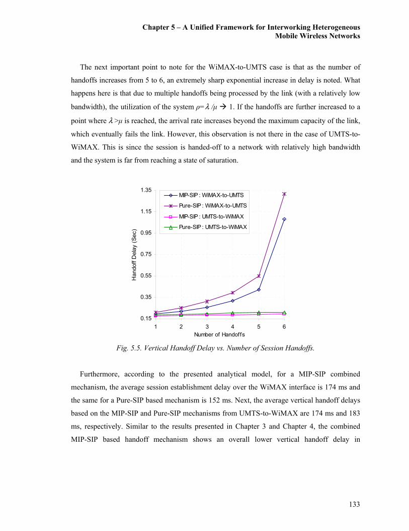
Chapter 5 – A Unified Framework for Interworking Heterogeneous
Mobile Wireless Networks
133
The next important point to note for the WiMAX-to-UMTS case is that as the number of
handoffs increases from 5 to 6, an extremely sharp exponential increase in delay is noted. What
happens here is that due to multiple handoffs being processed by the link (with a relatively low
bandwidth), the utilization of the system ρ=λ /µ � 1. If the handoffs are further increased to a
point where λ >µ is reached, the arrival rate increases beyond the maximum capacity of the link,
which eventually fails the link. However, this observation is not there in the case of UMTS-to-
WiMAX. This is since the session is handed-off to a network with relatively high bandwidth
and the system is far from reaching a state of saturation.
Fig. 5.5. Vertical Handoff Delay vs. Number of Session Handoffs.
Furthermore, according to the presented analytical model, for a MIP-SIP combined
mechanism, the average session establishment delay over the WiMAX interface is 174 ms and
the same for a Pure-SIP based mechanism is 152 ms. Next, the average vertical handoff delays
based on the MIP-SIP and Pure-SIP mechanisms from UMTS-to-WiMAX are 174 ms and 183
ms, respectively. Similar to the results presented in Chapter 3 and Chapter 4, the combined
MIP-SIP based handoff mechanism shows an overall lower vertical handoff delay in
0.15
0.35
0.55
0.75
0.95
1.15
1.35
1 2 3 4 5 6
Number of Handoffs
Handoff D
elay (Sec)
MIP-SIP : WiMAX-to-UMTS
Pure-SIP : WiMAX-to-UMTS
MIP-SIP : UMTS-to-WiMAX
Pure-SIP : UMTS-to-WiMAX
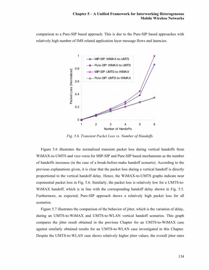
Chapter 5 – A Unified Framework for Interworking Heterogeneous
Mobile Wireless Networks
134
comparison to a Pure-SIP based approach. This is due to the Pure-SIP based approaches with
relatively high number of IMS related application layer message flows and latencies.
Fig. 5.6. Transient Packet Loss vs. Number of Handoffs.
Figure 5.6 illustrates the normalized transient packet loss during vertical handoffs from
WiMAX-to-UMTS and vice-versa for MIP-SIP and Pure-SIP based mechanisms as the number
of handoffs increases (in the case of a break-before-make handoff scenario). According to the
previous explanations given, it is clear that the packet loss during a vertical handoff is directly
proportional to the vertical handoff delay. Hence, the WiMAX-to-UMTS graphs indicate near
exponential packet loss in Fig. 5.6. Similarly, the packet loss is relatively low for a UMTS-to-
WiMAX handoff, which is in line with the corresponding handoff delay shown in Fig. 5.5.
Furthermore, as expected, Pure-SIP approach shows a relatively high packet loss for all
scenarios.
Figure 5.7 illustrates the comparison of the behavior of jitter, which is the variation of delay,
during an UMTS-to-WiMAX and UMTS-to-WLAN vertical handoff scenarios. This graph
compares the jitter result obtained in the previous Chapter for an UMTS-to-WiMAX case
against similarly obtained results for an UMTS-to-WLAN case investigated in this Chapter.
Despite the UMTS-to-WLAN case shows relatively higher jitter values, the overall jitter rates
0
0.2
0.4
0.6
0.8
1
1 2 3 4 5 6
Number of Handoffs
Packet Loss (Norm
alized)
MIP-SIP: WiMAX-to-UMTS
Pure-SIP: WiMAX-to-UMTS
MIP-SIP: UMTS-to-WiMAX
Pure-SIP: UMTS-to-WiMAX
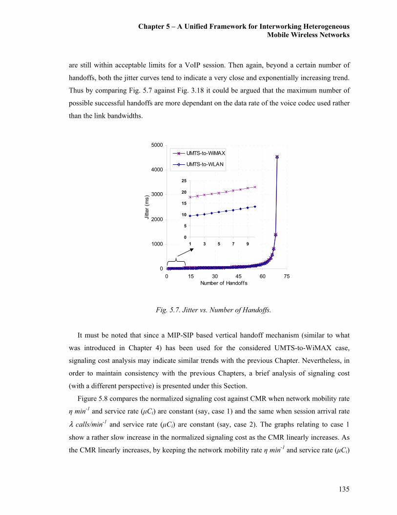
Chapter 5 – A Unified Framework for Interworking Heterogeneous
Mobile Wireless Networks
135
are still within acceptable limits for a VoIP session. Then again, beyond a certain number of
handoffs, both the jitter curves tend to indicate a very close and exponentially increasing trend.
Thus by comparing Fig. 5.7 against Fig. 3.18 it could be argued that the maximum number of
possible successful handoffs are more dependant on the data rate of the voice codec used rather
than the link bandwidths.
Fig. 5.7. Jitter vs. Number of Handoffs.
It must be noted that since a MIP-SIP based vertical handoff mechanism (similar to what
was introduced in Chapter 4) has been used for the considered UMTS-to-WiMAX case,
signaling cost analysis may indicate similar trends with the previous Chapter. Nevertheless, in
order to maintain consistency with the previous Chapters, a brief analysis of signaling cost
(with a different perspective) is presented under this Section.
Figure 5.8 compares the normalized signaling cost against CMR when network mobility rate
η min-1 and service rate (µCi) are constant (say, case 1) and the same when session arrival rate
λ calls/min-1 and service rate (µCi) are constant (say, case 2). The graphs relating to case 1
show a rather slow increase in the normalized signaling cost as the CMR linearly increases. As
the CMR linearly increases, by keeping the network mobility rate η min-1 and service rate (µCi)
0
1000
2000
3000
4000
5000
0 15 30 45 60 75
Number of Handoffs
Jitter (m
s)
UMTS-to-WiMAX
UMTS-to-WLAN
0
5
10
15
20
25
1 3 5 7 9
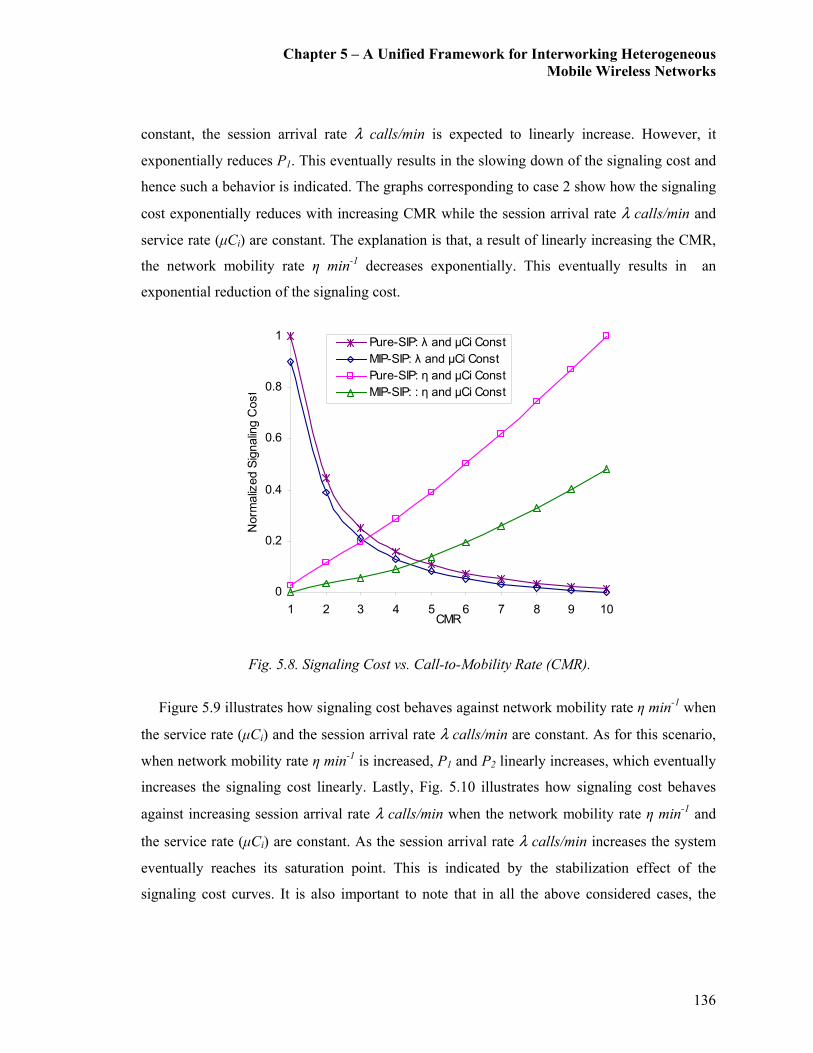
Chapter 5 – A Unified Framework for Interworking Heterogeneous
Mobile Wireless Networks
136
constant, the session arrival rate λ calls/min is expected to linearly increase. However, it
exponentially reduces P1. This eventually results in the slowing down of the signaling cost and
hence such a behavior is indicated. The graphs corresponding to case 2 show how the signaling
cost exponentially reduces with increasing CMR while the session arrival rate λ calls/min and
service rate (µCi) are constant. The explanation is that, a result of linearly increasing the CMR,
the network mobility rate η min-1 decreases exponentially. This eventually results in an
exponential reduction of the signaling cost.
Fig. 5.8. Signaling Cost vs. Call-to-Mobility Rate (CMR).
Figure 5.9 illustrates how signaling cost behaves against network mobility rate η min-1 when
the service rate (µCi) and the session arrival rate λ calls/min are constant. As for this scenario,
when network mobility rate η min-1 is increased, P1 and P2 linearly increases, which eventually
increases the signaling cost linearly. Lastly, Fig. 5.10 illustrates how signaling cost behaves
against increasing session arrival rate λ calls/min when the network mobility rate η min-1 and
the service rate (µCi) are constant. As the session arrival rate λ calls/min increases the system
eventually reaches its saturation point. This is indicated by the stabilization effect of the
signaling cost curves. It is also important to note that in all the above considered cases, the
0
0.2
0.4
0.6
0.8
1
1 2 3 4 5 6 7 8 9 10CMR
Norm
alized Signaling C
ost
Pure-SIP: λ and µCi Const
MIP-SIP: λ and µCi Const
Pure-SIP: η and µCi Const
MIP-SIP: : η and µCi Const

Chapter 5 – A Unified Framework for Interworking Heterogeneous
Mobile Wireless Networks
137
signaling method with lesser interactions with the IMS model (i.e., the MIP-SIP mechanism)
always indicated the lowest signaling cost.
0
0.2
0.4
0.6
0.8
1
10 30 50 70 90Mean Netw ork Mobility Rate (η /min)
Norm
alized Signaling Cost
Pure-SIP
MIP-SIP
Fig. 5.9. Signaling Cost vs. η when µCi and λ are constant.
0
0.2
0.4
0.6
0.8
1
10 30 50 70 90Mean Pkt Arrival Rate (λ calls/min)
Norm
alized Signaling Cost
Pure-SIP
MIP-SIP
Fig. 5.10. Signaling Cost vs. λ when µCi and η are constant.
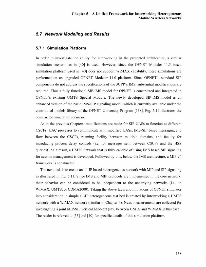
Chapter 5 – A Unified Framework for Interworking Heterogeneous
Mobile Wireless Networks
138
5.7 Network Modeling and Results
5.7.1 Simulation Platform
In order to investigate the ability for interworking in the presented architecture, a similar
simulation scenario as in [40] is used. However, since the OPNET Modeler 11.5 based
simulation platform used in [40] does not support WiMAX capability, these simulations are
performed on an upgraded OPNET Modeler 14.0 platform. Since OPNET’s standard SIP
components do not address the specifications of the 3GPP’s IMS, substantial modifications are
required. Thus a fully functional SIP-IMS model for OPNET is constructed and integrated to
OPNET’s existing UMTS Special Module. The newly developed SIP-IMS model is an
enhanced version of the basic IMS-SIP signaling model, which is currently available under the
contributed models library of the OPNET University Program [138]. Fig. 5.11 illustrates the
constructed simulation scenario.
As in the previous Chapters, modifications are made for SIP UASs to function as different
CSCFs, UAC processes to communicate with modified UASs, IMS-SIP based messaging and
flow between the CSCFs, roaming facility between multiple domains, and facility for
introducing process delay controls (i.e. for messages sent between CSCFs and the HSS
queries). As a result, a UMTS network that is fully capable of using IMS based SIP signaling
for session management is developed. Followed by this, below the IMS architecture, a MIP v4
framework is constructed.
The next task is to create an all-IP based heterogeneous network with MIP and SIP signaling
as illustrated in Fig. 5.11. Since IMS and MIP protocols are implemented in the core network,
their behavior can be considered to be independent to the underlying networks (i.e., to
WiMAX, UMTS, or CDMA2000). Taking the above facts and limitations of OPNET simulator
into consideration, a simple all-IP heterogeneous test bed is created by interworking a UMTS
network with a WiMAX network (similar to Chapter 4). Next, measurements are collected for
investigating a joint MIP-SIP vertical hand-off (say, between UMTS and WiMAX in this case).
The reader is referred to [35] and [40] for specific details of this simulation platform.
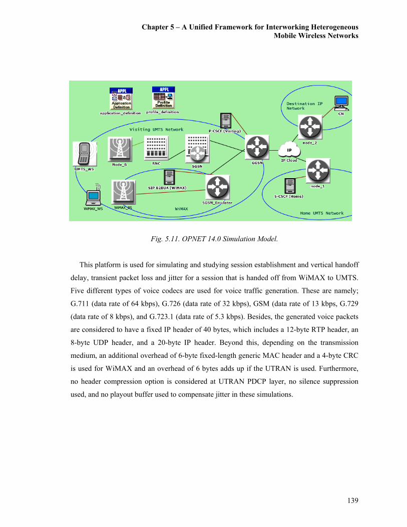
Chapter 5 – A Unified Framework for Interworking Heterogeneous
Mobile Wireless Networks
139
Fig. 5.11. OPNET 14.0 Simulation Model.
This platform is used for simulating and studying session establishment and vertical handoff
delay, transient packet loss and jitter for a session that is handed off from WiMAX to UMTS.
Five different types of voice codecs are used for voice traffic generation. These are namely;
G.711 (data rate of 64 kbps), G.726 (data rate of 32 kbps), GSM (data rate of 13 kbps, G.729
(data rate of 8 kbps), and G.723.1 (data rate of 5.3 kbps). Besides, the generated voice packets
are considered to have a fixed IP header of 40 bytes, which includes a 12-byte RTP header, an
8-byte UDP header, and a 20-byte IP header. Beyond this, depending on the transmission
medium, an additional overhead of 6-byte fixed-length generic MAC header and a 4-byte CRC
is used for WiMAX and an overhead of 6 bytes adds up if the UTRAN is used. Furthermore,
no header compression option is considered at UTRAN PDCP layer, no silence suppression
used, and no playout buffer used to compensate jitter in these simulations.

Chapter 5 – A Unified Framework for Interworking Heterogeneous
Mobile Wireless Networks
140
5.7.2 Simulation Results
Firstly the average session establishment and vertical handoff delays for the above scenarios
are investigated. The average MIP-SIP based VoIP session establishment delay over the UMTS
interface is 240 ms and the same over the WiMAX interface is 210 ms. The average vertical
handoff delays for IMS-SIP controlled VoIP sessions are as follows: A vertical handoff from
WiMAX-to-UMTS incurs 220 ms and UMTS-to-WiMAX incurs 195 ms. The large 3GPP SIP
message sizes and heavy application layer based IMS latencies (e.g., HSS look-up, SIP
ReINVITE message exchange, and routing all SIP signaling via the Home Network) are the
major contributors towards the vertical handoff delay. Furthermore, the above results show
rather close resemblance to the analytical results presented in Section 5.6. However, the
simulation results obtained for the average session establishment delay and the average handoff
delay are approximately 15-25% higher of the analytical results. Such a degree of variation in
the simulated result is unfortunately inevitable since the system initialization delays may affect
the final outcome. Nevertheless, it is a highly encouraging observation to obtain.
Secondly, the transient packet loss during a vertical handoff for different codecs is
investigated. This transient packet loss is observed by simulating a break-before-make type
handoff as described in detail in [35]. Fig. 5.12 and Fig. 5.13 illustrate the transient packet
losses for UMTS-to-WiMAX and WiMAX-to-UMTS vertical handoffs. As indicated, G.711
and G.726 codecs experience relatively higher levels of transient packet loss. The relatively
higher frame sizes used by these codecs are seen as the main contributor towards such high
transient packet losses. Furthermore, if closely observed, Fig. 5.12 and Fig. 5.13 have a close
resemblance to the trend shown in Fig. 3.10, which is the transient packet loss for a UMTS-to-
WLAN and WLAN-to-UMTS vertical handoff scenario. Therefore, Fig. 5.14 provides a
transient packet loss comparison for a UMTS-to-WiMAX handoff and a UMTS-to-WLAN
handoff. For all codecs used, UMTS-to-WLAN vertical handoff experiences relatively higher
packet loss.

Chapter 5 – A Unified Framework for Interworking Heterogeneous
Mobile Wireless Networks
141
0
10
20
30
40
50
1 2 3 4 5 6
Number of Handoffs
Packet Loss (KBytes)
G.711
G.726
GSM
G.729
G.723.1
Fig. 5.12. Transient Packet Loss for a UMTS-to-WiMAX Handoff.
0
20
40
60
80
100
120
1 2 3 4 5 6Number of Handoffs
Packet Loss (KBytes)
G.711
G.726
GSM
G.729
G.723.1
Fig. 5.13. Transient Packet Loss for a WiMAX-to-UMTS Handoff.

Chapter 5 – A Unified Framework for Interworking Heterogeneous
Mobile Wireless Networks
142
0
10
20
30
40
50
1 2 3 4 5 6
Number of Handoffs
Packet Loss (KBytes)
G.711: UMTS-to-WiMAX
G.726: UMTS-to-WiMAX
GSM: UMTS-to-WiMAX
G.729: UMTS-to-WiMAX
G.723.1: UMTS-to-WiMAX
G.711: UMTS-to-WLAN
G.726: UMTS-to-WLAN
GSM: UMTS-to-WLAN
G.729: UMTS-to-WLAN
G.723.1: UMTS-to-WLAN
Fig. 5.14. Transient Packet Loss Comparison for a UMTS-to-WiMAX Handoff and a UMTS-to-
WLAN Handoff.
Jitter, the variation of inter-arrival delay, is another factor which affects delay, especially
during a vertical handoff (when the link capacity changes, etc.). The effect on jitter across
different codec types is illustrated in Fig. 5.15. Fig. 5.15 also shows close resemblance to the
Jitter results given in Fig. 3.11 (b). The main factors affecting the jitter during a vertical
handoff for the considered VoIP data flow are the voice packet payload length and the
downlink data flow rate. Since the data flow rate depends on the serving wireless interface (i.e.,
WiMAX or UMTS), the codecs that uses the lowest voice packet payload lengths may
encounter the lowest jitter levels. Therefore, G.723.1, G.729, and GSM codecs with respective
packet payload sizes of 20 bytes, 10 bytes, and 32.5 bytes result in relatively lower jitter.
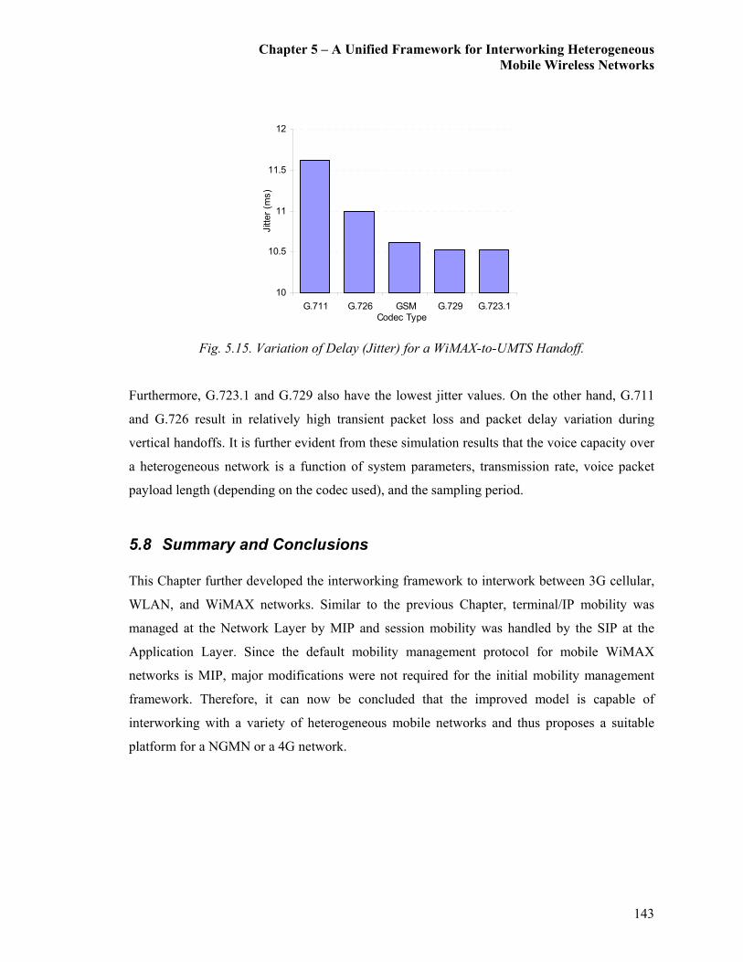
Chapter 5 – A Unified Framework for Interworking Heterogeneous
Mobile Wireless Networks
143
10
10.5
11
11.5
12
G.711 G.726 GSM G.729 G.723.1
Codec Type
Jitter (m
s)
Fig. 5.15. Variation of Delay (Jitter) for a WiMAX-to-UMTS Handoff.
Furthermore, G.723.1 and G.729 also have the lowest jitter values. On the other hand, G.711
and G.726 result in relatively high transient packet loss and packet delay variation during
vertical handoffs. It is further evident from these simulation results that the voice capacity over
a heterogeneous network is a function of system parameters, transmission rate, voice packet
payload length (depending on the codec used), and the sampling period.
5.8 Summary and Conclusions
This Chapter further developed the interworking framework to interwork between 3G cellular,
WLAN, and WiMAX networks. Similar to the previous Chapter, terminal/IP mobility was
managed at the Network Layer by MIP and session mobility was handled by the SIP at the
Application Layer. Since the default mobility management protocol for mobile WiMAX
networks is MIP, major modifications were not required for the initial mobility management
framework. Therefore, it can now be concluded that the improved model is capable of
interworking with a variety of heterogeneous mobile networks and thus proposes a suitable
platform for a NGMN or a 4G network.
Chapter 6 – Summary, Conclusions and Future Directions
144
V{tÑàxÜ I Summary, Conclusions, and Future Directions
6.1 Thesis Summary and Conclusions
The objective of this thesis was to propose a novel mobility-aware architecture for
interworking heterogeneous mobile data networks. More precisely, the proposed framework
conveniently enables any 3G cellular technology (such as UMTS or CDMA2000 systems),
WLANs, and WMANs (i.e., WiMAX systems) to interwork under a common mobility
management platform. In particular, within the centralized common mobility management
platform, both terminal mobility, and session mobility was managed in a real-time environment
for a roaming user.
The approach used for achieving the above objectives can be summarized into three main
stages as follows. Initially an in-depth review of the current literature published in the area was
carried out. This was essential for identifying and formulating the problem, defining the
motivations, trends, and issues.
The first stage of the research was to design and develop the initial architecture for
interworking the UMTS and the WLAN system (with limited mobility). This framework used
the IMS as a universal coupling mediator for real-time session negotiation and management.
Since the initial goal was merely to interwork between UMTS and WLAN systems, and the
design was somewhat close to a loose coupling model, the 3GPP’s IMS was the obvious
candidate to act as the coupling media. Furthermore, since it has already been used for
signaling within the IMS, SIP was chosen as the protocol for mobility and session
management. Thus the mobility management was initially Pure-SIP based and fully managed
at the Application Layer.
The second stage of the research further extended the existing framework to be capable of
interworking between different 3G cellular technologies (i.e., UMTS and CDMA2000) and the
WLAN. However, this required major architectural changes to the initial design. As a result, a

Chapter 6 – Summary, Conclusions and Future Directions
145
coupling framework similar to the 3GPP2’s IMS was chosen. It also required re-designing of
the entire mobility management framework. Instead of having a Pure-SIP based mobility
management framework, a MIP and SIP combined mobility management framework was
designed. Within this new framework, terminal/IP mobility was managed at the Network Layer
by MIP and session mobility was handled by SIP at the Application Layer.
The third and the last stage of this research further extended the model to interwork
between 3G cellular, WLAN, and BWA (WiMAX) networks. Similar to the second stage,
terminal/IP mobility was managed at the network layer by MIP and session mobility was
handled by SIP at the application layer. Since the default mobility management protocol for
mobile WiMAX networks is MIP, major modifications were not required for the initial
mobility management framework. Therefore, it can now be said that the improved model is
capable of interworking with a variety of heterogeneous mobile networks and thus proposes a
suitable platform for a NGMN or a 4G network.
An OPNET based simulation platform was used for modeling the proposed interworking
architectures. Vertical handoff for a given VoIP session from UMTS to WLAN (and vice
versa) using the proposed Pure-SIP and MIP-SIP based mobility management methods were
simulated and performance measurements were taken. Further, the same simulations were
carried out for UMTS to WiMAX handoffs under similar conditions (only for the MIP-SIP
based vertical handoff method). All simulated scenarios proved to be capable of performing
successful VoIP session handoffs between dissimilar networks whilst maintaining acceptable
QoS levels. The summarized results obtained from the OPNET based simulations are tabulated
in Table VI.I.
Further, an analytical model was derived for evaluating the proposed scheme for analyzing
the QoS metrics and measures involved in call or session mobility management under the
second stage. More precisely, QoS metrics that were analyzed are vertical handoff delay,
transient packet loss, jitter, and signaling overhead/cost. The primary assumption made for this
analysis was that, data call/session arrivals follow a Poisson process. The substance of the
derived results can be summarized as follows: The QoS analysis indicated that a MIP-SIP
based mobility management framework performs better than its predecessor, the Pure-SIP
based mobility management method. Also, the analysis results indicated that the QoS
performance for the investigated parameters were within the acceptable levels for real-time
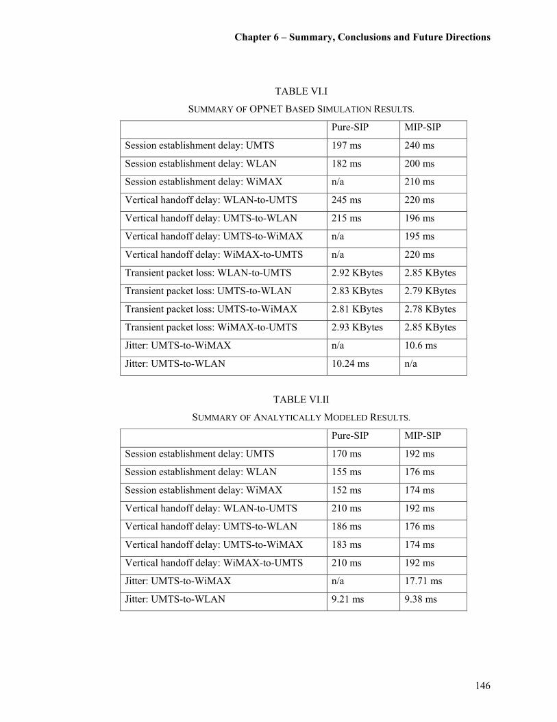
Chapter 6 – Summary, Conclusions and Future Directions
146
TABLE VI.I
SUMMARY OF OPNET BASED SIMULATION RESULTS.
Pure-SIP MIP-SIP
Session establishment delay: UMTS 197 ms 240 ms
Session establishment delay: WLAN 182 ms 200 ms
Session establishment delay: WiMAX n/a 210 ms
Vertical handoff delay: WLAN-to-UMTS 245 ms 220 ms
Vertical handoff delay: UMTS-to-WLAN 215 ms 196 ms
Vertical handoff delay: UMTS-to-WiMAX n/a 195 ms
Vertical handoff delay: WiMAX-to-UMTS n/a 220 ms
Transient packet loss: WLAN-to-UMTS 2.92 KBytes 2.85 KBytes
Transient packet loss: UMTS-to-WLAN 2.83 KBytes 2.79 KBytes
Transient packet loss: UMTS-to-WiMAX 2.81 KBytes 2.78 KBytes
Transient packet loss: WiMAX-to-UMTS 2.93 KBytes 2.85 KBytes
Jitter: UMTS-to-WiMAX n/a 10.6 ms
Jitter: UMTS-to-WLAN 10.24 ms n/a
TABLE VI.II
SUMMARY OF ANALYTICALLY MODELED RESULTS.
Pure-SIP MIP-SIP
Session establishment delay: UMTS 170 ms 192 ms
Session establishment delay: WLAN 155 ms 176 ms
Session establishment delay: WiMAX 152 ms 174 ms
Vertical handoff delay: WLAN-to-UMTS 210 ms 192 ms
Vertical handoff delay: UMTS-to-WLAN 186 ms 176 ms
Vertical handoff delay: UMTS-to-WiMAX 183 ms 174 ms
Vertical handoff delay: WiMAX-to-UMTS 210 ms 192 ms
Jitter: UMTS-to-WiMAX n/a 17.71 ms
Jitter: UMTS-to-WLAN 9.21 ms 9.38 ms

Chapter 6 – Summary, Conclusions and Future Directions
147
VoIP conversations. The summarized results obtained from the analytical modeling are
tabulated in Table VI.II.
The reason for both the analysis and OPNET simulations to concentrate on VoIP was
because voice traffic is the primary concern on any telecommunications provider. However,
similar analysis may be expanded for other applications based on FTP for file transferring,
HTTP for web traffic, and also other multimedia application traffic for video and audio
streaming. Hence the designed analytical model and the OPNET based simulation platform
could successfully be used by researches and network providers as a tool or test-bed for
studying the vertical handoff performance for the above mentioned applications regardless of
the interworked end networks.
6.2 Future Directions
Future works in regards to improving this architecture can be seen as two folds. Firstly, to
design and develop an authentication and authorization framework to the IEEE 802.21 MIH
protocol for ensuring data integrity, replay protection, confidentiality, and data origin
authentication. Further to reduce the latency during the authentication and key establishment
prior to a vertical handover between heterogeneous access networks, which support the IEEE
802.21 protocol.
The main motivations for this work is due to the fact that in the current heterogeneous
networking environments, security mechanisms including authentication and authorization are
individually specified and handled by each access technology. Therefore, it is highly important
for a centralized authentication and authorization framework to be defined for an inter-network
roaming user. To the best of our knowledge, architectures and protocols for such a security
framework has not been addressed in the ongoing development of the IEEE 802.21 MIH
protocol.
The significance of this work is to improve the experience for a roaming user in a
heterogeneous network by providing a unified security platform through authentication and
authorization mechanisms. Additionally, having a unified security mechanism will also
contribute towards minimizing the vertical handoff delay between heterogeneous access
networks. This is since security-related message exchanges during vertical handover can

Chapter 6 – Summary, Conclusions and Future Directions
148
significantly increase the handoff delay. As a result, in most cases, seamless service continuity
cannot be guarantied. Additionally, this will be able to secure the existing IEEE 802.21 MIH
protocol and enable authorization of MIH services. With such security in place, MIH protocol
entities and MIH services will be less vulnerable to potential security attacks and threats.
Secondly the issue of simultaneous network access will be explored. With the emergence of
Mobile WiMAX networks, which is sometimes considered as a 3G network, there are
possibilities for a 3G cellular service and a Mobile WiMAX service to co-exist. In such
situations, a roaming user may desire simultaneous access to both networks. Therefore, the
proposed architecture will be further improved to facilitate this multiple network accessing
feature.

Appendix A
149
TÑÑxÇw|å T Delay Analysis for an M/M/1 Queuing Model
A key feature of communication networks is the sharing of resources such as transmission
bandwidth, storage, and processing capacity. Since the need for such resources is unscheduled
and ad-hoc in nature, situations may arise when such resources are unavailable at the time of
need. This is a common situation, which leads to delay or loss of service in communication
networks. This appendix explains some fundamental models used for analyzing delay and
performance.
A.1 Delay Analysis and Little’s Law
In Queuing Theory, Little’s Law relates the average time spent in the system E[T] to the arrival
rate λ and the average number of customers in the system E[N] by the following formula:
E[N] = λ E[T] (A1)
However, the above expression does not specify what constitutes a “system,” which helps to
apply the Little’s Law for various scenarios. Therefore, the “system” could be an individual
transmission line, a multiplexer, a switch, or even a complete network. In the following
scenario, the Little’s Law is successfully applied for finding the average delay experienced by a
packet traversing in a packet switching network [157].
Figure A.1 shows an example of a packet switching network with inter connected packet
switches. It is assumed that when a packet arrives at a packet switch, the packet is routed
instantaneously and placed in a multiplexer to await transmission on an outgoing line. Thus
each packet switch can be viewed as consisting of a set of multiplexers. Now the Little’s
Formula can be applied to the entire network. Let Nnet be the total number of packets in the
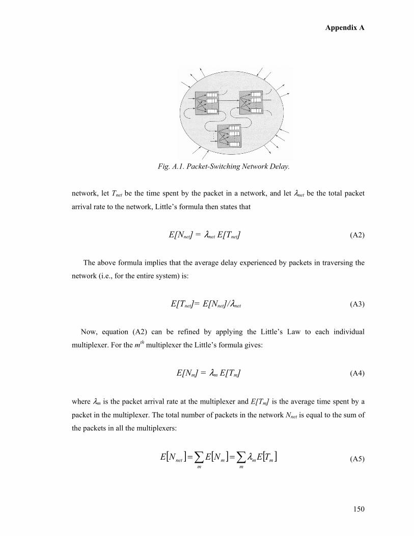
Appendix A
150
Fig. A.1. Packet-Switching Network Delay.
network, let Tnet be the time spent by the packet in a network, and let λnet be the total packet
arrival rate to the network, Little’s formula then states that
E[Nnet] = λnet E[Tnet] (A2)
The above formula implies that the average delay experienced by packets in traversing the
network (i.e., for the entire system) is:
E[Tnet]= E[Nnet]/λnet (A3)
Now, equation (A2) can be refined by applying the Little’s Law to each individual
multiplexer. For the mth multiplexer the Little’s formula gives:
E[Nm] = λm E[Tm] (A4)
where λm is the packet arrival rate at the multiplexer and E[Tm] is the average time spent by a
packet in the multiplexer. The total number of packets in the network Nnet is equal to the sum of
the packets in all the multiplexers:
[ ] [ ] [ ]m
m
m
m
mnet TENENE ∑∑ == λ (A5)
Appendix A
151
By combining (A3), (A4), and (A5), and expression for the total delay (i.e., end-to-end
daley) experienced by a packet in traversing the entire network can be obtained as:
[ ] [ ] [ ]m
m
m
net
netnetnet TENETE ∑== λλ
λ1
/ (A6)
Hence the average network delay depends on the overall arrival rates in the network, the
arrival rate to individual multiplexers, and the delay in each multiplexer. Equation (A6) is very
important since it incorporate the effects of routing (i.e., packet arrivals) and the capacity of the
transmission line on the network. Therefore, it can be directly used for evaluating the delay
performance of packet-switching networks.

Appendix B
152
TÑÑxÇw|å U Delay Analysis for Self-Similar Traffic
This section presents an analytical model for analyzing vertical session handoffs in a
heterogeneous mobile networking environment by considering a long-tailed distribution. The
analysis studies a G/M/1 queuing model where G is a Pareto distribution (rather than a Poisson
arrival distribution) to model data sessions that are subjected to vertical handoff in a packet
switched network. The vertical handoff mechanism and heterogeneous networking platform
(UMTS-WiMAX) used for the analysis is based on a MIP-SIP combined mechanism as
introduced under Chapter 5. The reminder of this section is organized as follows. The next
section briefly introduces the importance of the concept of self-similarity in regards to Internet
traffic analysis. Followed by is the section on Pareto/M/1 queuing analysis. Subsequently the
vertical handoff analysis and numerical results follow prior to the concluding remarks. The
analytical model and results presented under this section has contributed to [203] and [209].
B.1 Introduction
Internet traffic has been described as having one or more of the following related
characteristics: self-similar (or fractal) traffic traces, long-range dependence, burstiness on
multiple scales, and long or heavy-tailed packet inter-arrival times or service requirements
[204].
Self-similarity implies that the traffic looks the same over any time scale. Furthermore, as
first shown in [144], Poisson traffic does not have the same characteristic. Long-range
dependence is defined with respect to the autocorrelation function of a stationary discrete-time
stochastic process, R(k). It measures the level of correlation of the process with itself and
measured k periods away. The process is said to be long-range dependent if Σk R(k) = ∞, thus
implying that there is at best a slow and non-exponential decline in the autocorrelation function
with increasing lags k.

Appendix B
153
Furthermore, it may be argued that a self-similar process is also long-range dependent. The
Hurst parameter is often used to describe the degree of self-similarity in long-range processes
[204]. The concept of burstiness means that packets arrive in several short inter-arrival times
followed by a much longer time. Examples of long-tailed distributions are the Pareto, the log-
normal, the folded Cauchy, and the DFR form of the Weibull. In this analysis, a method for
studying Pareto queues is presented.
B.2 Pareto/M/1 Queuing Model
The standard form for the two-parameter Pareto distribution function defined over the
nonnegative real numbers can be written as:
( ) ( ) ( )0,11 ⟩∀+−= βααβ
xxF (B.1)
As a critical motivation for the subsequent procedure, such a distribution function can be
directly derived as a gamma (α,β) mixture of ordinary exponential densities. With no loss in
generality, the one-parameter version of the Pareto can be given as [205].
( ) ( )βxxF +−= 111 (B.2)
The corresponding density function is:
( ) ( ) 11
++=
ββ xxf (B.3)
and it is shown that the Pareto is indeed a long-tailed distribution, where β measures the initial
rate of decline of the density function curve [205].
Appendix B
154
In the following scenario, a Pareto arrival distribution into the queuing system is considered.
From the standard analysis of a G/M1 queue, the steady-state probability for the number of
customers Q in system just before an arrival is given for all nonnegative n as [206]:
{ } ( ) n
n rrqnQ −=== 1Pr (B.4)
For Pareto/M/1, the usual approach for obtaining the stationary delay time distributions and
system size probabilities requires solving a root finding problem involving the Laplace-
Stieltjes Transform (LST), A*(s), of the inter-arrival time distribution function [206], [156].
Thus r is the root of the fundamental branching process equation obtained by solving for z is:
( )[ ]zAz −= 1* µ (B.5)
where 1/µ is the expected service time [206]. The system utilization, ρ, which is λ/µ, where λ is
the customer arrival rate, and for the problem to have a non-trivial solution, one must have ρ <
1. The unique root of the fundamental equation of the branching process, say r, then becomes
the parameter of a geometric distribution for steady-state system sizes at the embedded arrival
points [205]. These geometric probabilities are then combined with convolutions of the
exponential service distribution to derive the stationary line-delay distribution.
Unfortunately, for the case of Pareto arrivals, a closed form for A*(s) does not exist. This
section uses a method proposed by Harris and Marchal for finding Coxian distribution fits for
arbitrary distribution functions using Laplace transform approximations [207]. It turns out that
their technique, which is called as the Transform Matching Method (TMM)) works especially
well for distributions defined over the full real line but without all moments. Thus use TMM
for A*(s) and then use Newton’s method to solve for the root r. Once the root is found, the
queue and system waiting-time distribution functions can easily be derived for t ≥ 0 as [206]:
( ) ( )trq retW −−−= 11 µ
(B.6)
Appendix B
155
( ) ( )tretW −−−= 11 µ (B.7)
A close observation of the above queue and system waiting-time distribution functions
indicates that they have the same functional form as the M/M/1 queue except with r replacing
ρ. Thus the expected queue waiting time, Wq, and system waiting time, W, can be expressed as
follows [206] [205]:
)1( r
rWq
−=
µ (B.8)
)1(
1
rW
−=
µ (B.9)
B.3 Vertical Handoff Analysis
An analytical model is derived for the scheme proposed under Chapter 5 for evaluating vertical
session handoff performance for Internet data traffic with Pareto based arrivals.
B.3.1 Handoff Delay
A standard vertical handoff delay during mid-session mobility consists of the following sub-
procedures (or delays); D1 = link layer handoff delay, D2 = movement detection delay, D3 =
address allocation delay, D4 = session re-configuration delay, and D5 = packet re-transmission
delay [154]. The vertical handoff delay at the network layer (and above) are calculated
independent of the link layer delay D1 and mainly consist of D3 and D4. According to our
proposed architecture for IMS based vertical handoff, there is no DHCP related address
allocation; hence it can be argued that is D4 the main contributor for network layer based
vertical handoff delay, D. The session re-configuration delay, D4 mainly consists of the
previously mentioned IMS based session negotiation and handoff and HSS related message
exchange delays.
Appendix B
156
In order to derive an expression for D, we must first derive an expression for analyzing the
end-to-end transmission delay. Hence, let us assume that the end-to-end transmission delay for
a packet size S sent from network A to network B over a number of hops via a wireless and
wired links to be expressed as follows:
wwlwwlba LLDDHSD +++=− ),( (B.10)
where, Dwl is the total delay at the wireless interface (say, BS), Dw is the total delay at the wired
link, Lwl is the latency of the wireless link, and Lw is the latency of the wired link. In order to
derive Dwl and Dw a Pareto/M/1 queuing model has been applied to the packet flow of the data
session at the wireless BS and other networking elements of the IMS on the path of signaling
and data routing of Fig. 5.2.
It is important to note that to apply the results of Pareto/M/1 analysis, it is assumed that the
service times that a packet experiences at different nodes are independent of each other.
However, this assumption is untrue, since the service time is proportional to the packet length,
and a packet has the same length as it traverses the network. Nevertheless, it has been found
that this independence assumption can be used in large networks [156]. Using the results form
the Pareto/M/1 model, expressions for Dwl and Dw can be expressed as follows:
( )wlwl
wlr
D−
=1
1
µ (B.11)
where, µwl is the service rate and rwl is the root of the fundamental branching process equation
obtained by solving for z at the wireless interface. For clarity and convenience sake, the units
for µwl are changed from packets/sec to bits/sec. If the probability density function of for packet
size, x, in bits be µe-µx with a mean packet length of 1/µ bits/packet, and the capacity of
communication channel i be Ci bits/sec. The product µCi is then the service rate in packets/sec.
Therefore, for channel i, we have
( )wli
wlrC
D−
=1
1
µ (B.12)
Appendix B
157
where, Dwl includes both queuing and transmission delays. Also note that the mean packet size
does not depend on the channel as the capacity and the input rates do. However, when Dw is
considered, it can be expressed as a collection of delays of multiple Pareto/M/1 queues. It is
also assumed that if the output of several Pareto/M/1 servers feed into the input queue of
another server, the resulting input process is also a Pareto process, with mean equal to the sum
of the means of the feeding process. This assumption has been derived from a similar
assumption made for a G/M/1 queue in [156]. Thus the total wired network delay experienced
by a packet can be expressed as:
( )
−= ∑
wjj
j
w
wrC
D1
11
µλ
λ (B.13)
where, λw is the total packet arrival rate to the network, λj is the packet arrival rate at jth node,
and µCj is the service rate in packets/sec at the jth node. Thus by combining equations (B.10),
(B.12) and (B.13) we get:
( ) ( ) wwl
wjj
j
wwli
ba LLrCrC
HSD ++
−+
−= ∑−
1
11
1
1),(
µλ
λµ (B.14)
Now, an expression for the vertical handoff delay D can be expressed by applying (B.14) to
the entire IMS signaling flow involved in the vertical handoff mechanism as illustrated in Fig.
5.3. Thus the final expression for D is a combination of the following end-to-end delay
components as indicated in equation (B.15).
DIMS = D(SMIPReq, HUMTS-MIP-HA) + D(SMIPRep, HUMTS-MIP-HA)
+ D(SMIP-BU, HUMTS-CN) + D(SReINVITE, HWiMAX-CN)
+ D(S183-SP, HWiMAX-CN) + D(SPRACK, HWiMAX-CN)
+ D(SOK, HWiMAX-CN) + D(SUPDATE, HWiMAX-CN)
+ D(SOK, HWiMAX-CN) + D(SACK, HWiMAX-CN)
Appendix B
158
+D(SBYE,HUMTS-CN) + D(SOK,HCN-UMTS)+ ∆ (B.15)
where, ∆ is the additional IMS (application layer) related latency due to HSS lookup process.
The important point to note here is that the derivation of equation (B.15) has not taken into
account the errors that may cause various messages to be damaged or lost. This is since for
successful session establishment, the entire message flow must take place and if any message is
damaged or lost the vertical handoff process will fail. Hence it has been assumed that the
channel is error free during the process of the vertical handoff taking place. It is also worth
reminding that make-before-break handoff is applied in the proposed handoff scenarios, which
helps compensate for large handoff delays. For the purpose of a complete analysis of vertical
handoff delay, the standard straight forward case of break-before-make handoff scenario is
used.
B.3.2 Packet Loss
The total packet loss (Pkt_loss) during a vertical session handoff can be defined as the sum of
all lost packets during the vertical handoff while the MN is receiving the downlink data
packets. It is assumed that the packet loss begins when the Layer 2 handoff is detected and all
in-flight packets are lost during the vertical handoff time. Thus, it can be expressed as:
mwl
ad
NDT
lossPkt ××
+= λ
2
1_ (B.16)
where, Tad is the time interval between P-CSCF discovery times, λwl is the downlink packet
arrival rate at the wireless interface, and Nm is the average number of vertical handoffs during a
single session [154]. Nm plays a major role in the calculation of packet loss since the packet
loss due to vertical handoff is directly proportionate to the number of handoffs it is subjected
within a given session.
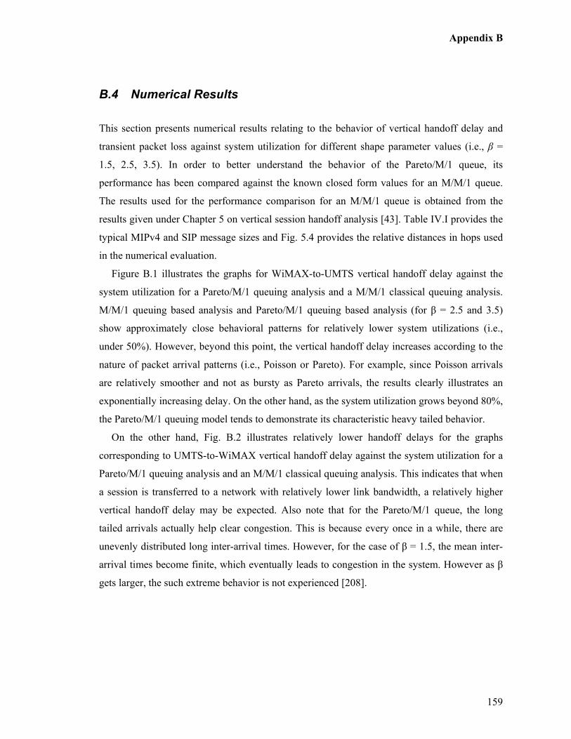
Appendix B
159
B.4 Numerical Results
This section presents numerical results relating to the behavior of vertical handoff delay and
transient packet loss against system utilization for different shape parameter values (i.e., β =
1.5, 2.5, 3.5). In order to better understand the behavior of the Pareto/M/1 queue, its
performance has been compared against the known closed form values for an M/M/1 queue.
The results used for the performance comparison for an M/M/1 queue is obtained from the
results given under Chapter 5 on vertical session handoff analysis [43]. Table IV.I provides the
typical MIPv4 and SIP message sizes and Fig. 5.4 provides the relative distances in hops used
in the numerical evaluation.
Figure B.1 illustrates the graphs for WiMAX-to-UMTS vertical handoff delay against the
system utilization for a Pareto/M/1 queuing analysis and a M/M/1 classical queuing analysis.
M/M/1 queuing based analysis and Pareto/M/1 queuing based analysis (for β = 2.5 and 3.5)
show approximately close behavioral patterns for relatively lower system utilizations (i.e.,
under 50%). However, beyond this point, the vertical handoff delay increases according to the
nature of packet arrival patterns (i.e., Poisson or Pareto). For example, since Poisson arrivals
are relatively smoother and not as bursty as Pareto arrivals, the results clearly illustrates an
exponentially increasing delay. On the other hand, as the system utilization grows beyond 80%,
the Pareto/M/1 queuing model tends to demonstrate its characteristic heavy tailed behavior.
On the other hand, Fig. B.2 illustrates relatively lower handoff delays for the graphs
corresponding to UMTS-to-WiMAX vertical handoff delay against the system utilization for a
Pareto/M/1 queuing analysis and an M/M/1 classical queuing analysis. This indicates that when
a session is transferred to a network with relatively lower link bandwidth, a relatively higher
vertical handoff delay may be expected. Also note that for the Pareto/M/1 queue, the long
tailed arrivals actually help clear congestion. This is because every once in a while, there are
unevenly distributed long inter-arrival times. However, for the case of β = 1.5, the mean inter-
arrival times become finite, which eventually leads to congestion in the system. However as β
gets larger, the such extreme behavior is not experienced [208].
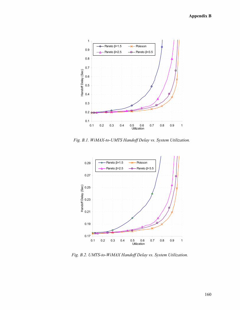
Appendix B
160
0.1
0.2
0.3
0.4
0.5
0.6
0.7
0.8
0.9
1
0.1 0.2 0.3 0.4 0.5 0.6 0.7 0.8 0.9 1Utilization
Handoff Delay (Sec)
Pareto β=1.5 Poisson
Pareto β=2.5 Pareto β=3.5
Fig. B.1. WiMAX-to-UMTS Handoff Delay vs. System Utilization.
0.17
0.19
0.21
0.23
0.25
0.27
0.29
0.1 0.2 0.3 0.4 0.5 0.6 0.7 0.8 0.9 1Utilization
Handoff D
elay (Sec)
Pareto β=1.5 Poisson
Pareto β=2.5 Pareto β=3.5
Fig. B.2. UMTS-to-WiMAX Handoff Delay vs. System Utilization.
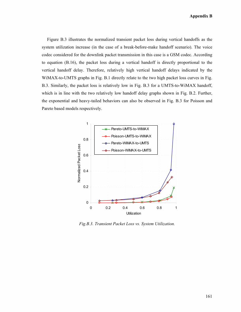
Appendix B
161
Figure B.3 illustrates the normalized transient packet loss during vertical handoffs as the
system utilization increase (in the case of a break-before-make handoff scenario). The voice
codec considered for the downlink packet transmission in this case is a GSM codec. According
to equation (B.16), the packet loss during a vertical handoff is directly proportional to the
vertical handoff delay. Therefore, relatively high vertical handoff delays indicated by the
WiMAX-to-UMTS graphs in Fig. B.1 directly relate to the two high packet loss curves in Fig.
B.3. Similarly, the packet loss is relatively low in Fig. B.3 for a UMTS-to-WiMAX handoff,
which is in line with the two relatively low handoff delay graphs shown in Fig. B.2. Further,
the exponential and heavy-tailed behaviors can also be observed in Fig. B.3 for Poisson and
Pareto based models respectively.
0
0.2
0.4
0.6
0.8
1
0 0.2 0.4 0.6 0.8 1
Utilization
Norm
alized Packet Loss
Pareto-UMTS-to-WiMAX
Poisson-UMTS-to-WiMAX
Pareto-WiMAX-to-UMTS
Poisson-WiMAX-to-UMTS
Fig.B.3. Transient Packet Loss vs. System Utilization.
References
162
References
[1] IEEE, "IEEE Std 802.11-1997 Information Technology – Telecommunications and
Information Exchange between Systems-Local and Metropolitan Area Networks –
specific Requirements – Part II: Wireless LAN Medium Access Control (MAC) and
Physical Layer (PHY) Specifications," IEEE Std 802.11-1997, 1997.
[2] IEEE, "Supplement to IEEE Standard for Information Technology –
Telecommunications and Information Exchange Between Systems – Local and
Metropolitan Area Networks-Specific Requirements – Part II: Wireless LAN Medium
Access Control (MAC) and Physical Layer (PHY) Specifications: Higher-speed
Physical Layer extension in the 2.4 GHz band," IEEE Std. 802.11b-1999, 2000.
[3] IEEE, "Supplement to IEEE Standard for Information Technology telecommunications
and information exchange between systems – local and metropolitan area networks –
specific requirements. Part II: wireless LAN Medium Access Control (MAC) and
Physical Layer (PHY) specifications: high – speed physical layer in the 5 GHz band,”
IEEE Std. 802.11a-1999, 1999.
[4] IEEE, "IEEE standard for Information Technology – Telecommunications and
Information exchange between systems – local and metropolitan area networks –
specific requirements Part II: wireless LAN medium access control (MAC) and
physical layer (PHY) specifications," IEEE Std. 802.11g-2003, 2003.
[5] IEEE, "Wireless LAN Medium Access Control (MAC) and Physical Layer (PHY)
specifications: Amendment 4: Enhancements for Higher Throughput.,”
P802.11n/D3.00, 2008.
[6] T. Paul and T. Ogunfunmi, "Wireless LAN Comes of Age: Understanding the IEEE
802.11n Amendment," IEEE Circuits and Systems Magazine, vol. 8, pp. 28-54, 2008.
[7] IEEE, "Part 11: Wireless Medium Access Control (MAC) and Physical Layer (PHY)
specifications: Amendment 5: Spectrum and transmit power management extensions in
the 5 GHz band in Europe," IEEE Std 802.11h-2003, 2003.
[8] D. Qiao and S. Choi, "New 802.11h mechanisms can reduce power consumption," IT
Professional, vol. 8, no. 2, pp. 43-48, March-April 2006.

References
163
[9] C. Eklund, R. B. Marks, K. L. Stanwood, and S. Wang, "IEEE Standard 802.16: A
Technical Overview of the Wireless MAN Air Interface for Broadband Wireless
Access," IEEE Communications, vol. 40, no. 6, pp. 98-107, June 2002.
[10] IEEE, "IEEE Standard for Local and metropolitan area networks — Part 16: Air
Interface for Fixed Broadband Wireless Access Systems," IEEE Standard 802.16-2001,
2001.
[11] IEEE, "IEEE Standard for Local and metropolitan area networks — Part 16: Air
Interface for Fixed Broadband Wireless Access Systems — Amendment 2: Medium
Access Control Modifications and Additional Physical Layer Specifications for 2-11
GHz," IEEE Standard 802.16a-2003, 2003.
[12] IEEE, "IEEE Standard for Local and metropolitan area networks — Part 16: Air
Interface for Fixed Broadband Wireless Access Systems — Amendment 1: Detailed
System Profiles for 10–66 GHz," IEEE Standard 802.16c-2002, 2002.
[13] IEEE, "Draft Amendment to IEEE Standard for Local and Metropolitan Area Networks
- Part 16: Air Interface for Fixed Broadband Wireless Access Systems- Amendment 3:
Detailed System Profiles for 2-11 GHz," IEEE Project P802.16d, 2003.
[14] IEEE, "Air Interface for Fixed Broadband Wireless Access Systems," IEEE STD
802.16 - 2004, October 2004.
[15] IEEE, "Air Interface for Fixed and Mobile Broadband Wireless Access Systems," IEEE
P802.16e/D12, February 2005.
[16] 3GPP, "Universal Mobile Telecommunications System (UMTS); Technical
Specifications and Technical Reports for a UTRAN-based 3GPP system (3GPP TS
21.101 version 3.17.0 Release 1999)," ETSI TS 121 101 V3.17.0, 2008.
[17] 3GPP, "3rd Generation Partnership Project; Technical Specification Group Services and
System Aspects; General Packet Radio Service (GPRS); Service description, Stage 1
(3G TS 22.060 version 3.1.0)," 3G TS 22.060 V3.1.0, 1999.
[18] 3GPP2, "HRPD/1XRTT and 3GPP E-UTRAN (LTE) Interworking and Inter-
Technology Handoff - Stage 1 Requirements," 3GPP2 S.R0129-0, 2008.
[19] 3GPP2, "cdma2000 High Rate Packet Data Air Interface Specification," 3GPP2
C.S0024-B, 2006.

References
164
[20] 3GPP2, "Introduction to cdma2000 Standards for Spread Spectrum Systems," 3GPP2
C.S0001-D, 2005.
[21] ITU-T, "Detailed specifications of the radio interfaces of International Mobile
Telecommunications-2000 (IMT-2000)," Recommendation M.1457-7, 2008.
[22] 3GPP, "Universal Mobile Telecommunications System (UMTS); UTRA High Speed
Downlink Packet Access (HSDPA); Overall description; Stage 2," ETSI TS 125 308
V5.7.0, 2004.
[23] A. Jamalipour, The Wireless Mobile Internet: architectures, protocols, and services,
England: John Wiley & Sons, 2003.
[24] J.-C. Chen and T. Zhang, IP-Based Next-Generation Wireless Networks, John Wiley &
Sons, 2004.
[25] A. K. Salkintzis, C. Fors, and R. Pazhyannur, "WLAN-GPRS integration for next-
generation mobile data networks," IEEE Wireless Communications, vol. 9, no. 5, pp.
112-124, June 2002.
[26] K. D. Wong, M. Barton, B. Kim, V. K. Varma, S. Ramesh, G. Hayward, and J. A.
Friedhoffer, "UMTS signaling over 802.11 wireless LAN," in Proceedings of at the
IEEE Vehicular Technology Conference-Fall, Orlando, Florida, USA, October 2003.
[27] V. K. Varma, S. Ramesh, K. D. Wong, M. Barton, G. Hayward, and J. A. Friedhoffer,
"Mobility management in integrated UMTS/WLAN networks," in Proceedings of the
IEEE International Conference on Communications, Anchorage, Alaska, May 2003.
[28] A. K. Salkintzis, "Interworking techniques and architectures for WLAN/3G integration
toward 4G mobile data networks," IEEE Wireless Communications, vol. 11, no. 3 pp.
50-61, 2004.
[29] A. K. Salkintzis, "WLAN/3G interworking architectures for next generation hybrid data
networks," in Proceedings of the IEEE International Conference on Communications,
Paris, France, June 2004.
[30] K. Pahlavan, P. Krishnamurthy, A. Hatami, M. Ylianttila, J. P. Makela, R. Pichna, and
J. Vallstron, "Handoff in hybrid mobile data networks," IEEE Personal
Communications, vol. 7, no. 2, pp. 34 - 47, 2000.
[31] 3GPP, "IP Multimedia Subsystem (IMS)," 3GPP TS 23.228 Version 6.10.0 Release 6,
2005.

References
165
[32] Yi-Bing Lin, Ai-Chun Pang, Wireless and Mobile All-IP Networks, John Wiley & Sons,
2005.
[33] K. S. Munasinghe, A. Jamalipour, and B. Vucetic, "Interworking between WLAN and
3G Cellular Networks: An IMS Based Architecture," in Proceedings of the IEEE
International Conference on Wireless Broadband and Ultra Wideband
Communications, Sydney, Australia, March 2006.
[34] K. S. Munasinghe and A. Jamalipour, "Interworking of WLAN-UMTS Networks: An
IMS-based Platform for Session Mobility," IEEE Communications, vol. 46, no. 9, pp.
184-191, 2008.
[35] K. S. Munasinghe and A. Jamalipour, "A 3GPP-IMS based Approach for Converging
Next Generation Mobile Data Networks," in Proceedings of the IEEE International
Conference on Communications, Glasgow, Scotland, UK, June 2007.
[36] K. S. Munasinghe and A. Jamalipour, "Mobility Management QoS Measures
Evaluation for Next Generation Mobile Networks," in Proceedings of the Tyrrhenian
Workshop on Digital Communications, Naples, Italy, September 2007.
[37] K. S. Munasinghe and A. Jamalipour, "Mobility Management QoS Measures
Evaluation for Next Generation Mobile Networks," in Wireless Communications: CNIT
Thyrrenian Symposium Series: Signals and Communications Technology, P. Silvano,
Ed. USA: Springer, pp. 265-280, 2008.
[38] K. S. Munasinghe and A. Jamalipour, "An Analytical Evaluation of Mobility
Management in Integrated WLAN-UMTS Networks," Elsevier Computers and
Electrical Engineering, 2009 (in press).
[39] K. S. Munasinghe and A. Jamalipour, "Analysis of Signaling Cost for a Roaming User
in a Heterogeneous Mobile Data Network," in Proceedings of IEEE Global
Communications Conference, New Orleans, Louisiana, USA, November 2008.
[40] K. S. Munasinghe and A. Jamalipour, "A Unified Mobility and Session Management
Platform for Next Generation Mobile Networks," in Proceedings of IEEE Global
Communications Conference, Washington D.C., USA, November 2007.
[41] K. S. Munasinghe and A. Jamalipour, "Analytical Modeling of IMS based Interworking
in Heterogeneous Mobile Data Networks," in Proceedings of International Conference

References
166
on Signal Processing and Communication Systems, Gold Coast, Australia, December
2007.
[42] K. S. Munasinghe, M. R. Kibria, and A. Jamalipour, "Designing VoIP Session
Management over Interworked WLAN-3G Cellular Networks," IEEE Wireless
Communications, vol. 15, no. 4, pp. 86-94, 2008.
[43] K. S. Munasinghe and A. Jamalipour, "Interworked WiMAX-3G Cellular Networks:
An Architecture for Mobility Management and Performance Evaluation," IEEE
Transactions on Wireless Communications, 2008 (in press).
[44] K. S. Munasinghe and A. Jamalipour, "An Architecture for Mobility Management in
Interworked 3G Cellular and WiMAX Networks," in Proceedings of the IEEE Wireless
Telecommunications Symposium, Pomona, California, USA, April 2008.
[45] S. Bhavsar, "WLAN-Cellular Integration for Mobile Data Networks," in Proceedings of
Communications Networks and Services Research Conference, New Brunswick,
Canada, May 2003.
[46] Y. Xiao, Y. Pan, K. K. Leung, and X. Du, "Architecture, Mobility Management, and
Quality of Service for Integrated 3G and WLAN Networks," Wiley Interscience:
Journal of Wireless Communications and Mobile Computing, vol. 5, no. 7, pp. 805-823,
2005.
[47] W. Song, W. Zhuang, and A. Saleh, "Interworking of 3G cellular networks and wireless
LANs," International Journal of Wireless and Mobile Computing, vol. 2, no.4, pp. 237-
247, 2007.
[48] J.-y. Song, S.-w. Lee, and D.-h. Cho, "Hybrid coupling scheme for UMTS and wireless
LAN interworking," in Proceedings of at the IEEE Vehicular Technology Conference-
Fall, Orlando, Florida, Oct. 2003.
[49] L. Chunming and Z. Chi, "An improved interworking architecture for UMTS-WLAN
tight coupling," in Proceedings of the IEEE Wireless Communications and Networking
Conference, Atlanta, Georgia, USSA, March 2005.
[50] M. Lee, G. Kim, S. Park, S. Jun, J. Nah, and O. Song, "Efficient 3G/WLAN
Interworking Techniques for Seamless Roaming Services with Location-Aware
Authentication," in Lecture Notes in Computer Science Networking, R. Boutaba, Ed.
Berlin / Heidelberg: Springer, pp. 370-381, May 2005.

References
167
[51] A. K. Salkintzis, Mobile Internet: Enabling Technologies and Services: CRC Press,
2004.
[52] J. M. a. K. A.-B. Xin Gang Wang, "An adaptive QoS framework for integrated cellular
and WLAN networks," in Proceedings of the PG Networking Conference, Liverpool,
UK, June 2003.
[53] D. Findlay, H. Flygare, R. Hancock, T. Haslestad, E. Hepworth, D. Higgins, and S.
McCann, "3G interworking with wireless LANs," in Proceedings of the International
Conference on 3G Mobile Communication Technologies, London, UK, May 2002.
[54] ETSI, "Requirements and Architectures for Interworking between HIPERLAN/2 and
3rd Generation Cellular systems," ETSI TR 101 957 Version 1.1.1, 2001.
[55] J. C. Chen and H. W. Lin, "A gateway approach to mobility integration of GPRS and
wireless LANs," IEEE Wireless Communications, vol. 12, no. 2, pp. 86 - 95, 2005.
[56] Y. Min-hua, L. Yu, and Z. Hui-min, "The Mobile IP handoff between hybrid
networks," in Proceedings of the IEEE International Symposium on Personal, Indoor
and Mobile Radio Communications, Beijing, China, September 2003.
[57] C. Chang, "A Mobile-IP based Mobility System for Wireless Metropolitan Area
Networks," in Proceedings of International Conference Workshops on Parallel
Processing, Oslo, Norway, June 2005.
[58] T. Sanguankotchakorn and P. Jaiton, "Effect of Triangular Routing in Mixed IPv4/IPv6
Networks," in Proceedings of International Conference on Networking, Cancun,
Mexico, April 2008.
[59] H. H. Choi and D. H. Cho, "Mobility management based on mobile IP in mixed
IPv4/IPv6 networks," in Proceedings of the IEEE Vehicular Technology Conference-
Fall, Orlando, Florida, USA, October 2003.
[60] A. C. Pang, J. C. Chen, Y. K. Chen, and P. Agrawal, "Mobility and session
management: UMTS vs. cdma2000," IEEE Wireless Communications, vol. 11, no. 4,
pp. 30-43, August 2004.
[61] S.-L. Tsao and C.-C. Lin, "VGSN: a gateway approach to interconnect UMTS/WLAN
networks," in Proceedings of the IEEE International Symposium on Personal, Indoor
and Mobile Radio Communications, Lisbon, Portugal, September 2002.

References
168
[62] P. M. Feder, N. Y. Lee, and S. Martin-Leon, "A seamless mobile VPN data solution for
UMTS and WLAN users," in Proceedings of the International Conference on 3G
Mobile Communication Technologies, London, UK, June 2003.
[63] 3GPP, "3GPP system to Wireles Local Area Network (WLAN) interworking," 3GPP
TS 23.234 version 6.4.0 Release 6, 2005.
[64] 3GPP, "3GPP system to Wireless Local Area Network (WLAN) Interworking;
Functional and architectural definition," 3GPP TR 23.934 version 1.0.0 Release 6,
2002.
[65] 3GPP, "Feasibility study on 3GPP system to Wireles Local Area Network (WLAN)
interworking," 3GPP TR 22.934 version 6.2.0 Release 6, 2003.
[66] F. A. Phiri and M. B. Murthy, "WLAN-GPRS Tight Coupling Based Interworking
Architecture with Vertical Handoff Support," Wireless Personal Communications, vol.
40, no. 2, pp. 137-144, 2007.
[67] D. I. Axiotis, T. Al-Gizawi, K. Peppas, E. N. Protonotarios, F. I. Lazarakis, C.
Papadias, and P. I. Philippopoulos, "Services in interworking 3G and WLAN
environments," IEEE Wireless Communications, vol. 11, no. 5, pp. 14-20, 2004.
[68] H. Hu and Y. a. Liu, "Key Technologies of WLAN Accessing 3GPP PS Based
Services," in Proceedings the IEEE Circuits and Systems Symposium on Emerging
Technologies: Frontiers of Mobile and Wireless Communication, Shanghai, China,
May 2004.
[69] 3GPP2, "3GPP2 – WLAN Interworking - Stage 1 Requirements," 3GPP2 S.R0087-0,
July 2004.
[70] Y.-G. Hong, J.-S. Park, and H.-J. Kim, "IPv6 based CDMA/WLAN heterogeneous
network interworking," in Proceedings of International Conference on Advanced
Communication Technology, Korea, February 2005.
[71] Z. Huang, Yang, P., and Deng, H., "QoS based handoff for CDMA2000-WLAN
interworking," in Proceedings of ACM International Workshop on Quality of Service
and Security for Wireless and Mobile Networks, Spain, October 2006.
[72] R. S. Gerardo Gómez, End-to-end Quality of Service Over Cellular Networks: Data
Services Performance and Optimization in 2G/3G: John Wiley and Sons, 2005.
References
169
[73] H. C. W. Kim, "A seamless handover between cdma2000 and WLAN for 3G-WLAN
interworking service continuity," in Proceedings of Advanced Industrial Conference on
Telecommunications, Lisbon, Portugal, July 2005.
[74] I. Roh, M.-H. Rim, S. Shin, and H.-S. Jang, "Radio resource requirements in the IMT-
2000 network," in Proceedings of International Conference on Management of
Engineering and Technology, Portland, OR, USA, July 2001.
[75] J. Nah, J. Yoo, J. Yu, Y. Lee, and H. H. Lee, "Mobile signaling structures of IMT-2000
exchange," in Proceedings of the IEEE International Conference on Personal Wireless
Communication, Jaipur, India, February 1999.
[76] S. Kim, H. Cho, H. Hahm, S. Lee, and M. S. Lee, "Interoperability between UMTS and
cdma2000 networks," IEEE Wireless Communications, vol. 10, no. 1, pp. 22-28, 2003.
[77] C. P. Makaya, Samuel, "An Interworking Architecture for Heterogeneous IP Wireless
Networks," in Proceedings of International Conference on Wireless and Mobile
Communications, French Caribbean, March 2007.
[78] C. Makaya and S. Pierre, "Reliable Integrated Architecture for Heterogeneous Mobile
and Wireless Networks," JOURNAL OF NETWORKS, vol. 2, no. 6, pp. 24-32, 2007.
[79] D. Johnson, C. Perkins, and J. Arkko, "Mobility Support in IPv6," IETF RFC 3775,
June 2004.
[80] H. Soliman, C. Castelluccia, K. El-Malki, and L. Bellier, "Hierarchical Mobile IPv6
Mobility Management (HMIPv6)," IETF RFC 4140, August 2005.
[81] TIA/EIA, "Interworking/Interoperability between DCS1900 and IS-41 Based MAPs for
1800 MHz Personal Communications Systems — Phase I," TIA/EIA/IS-129, July 1996.
[82] 3GPP2, "Network Interworking between GSM MAP and ANSI-41 MAP Rev. B,”
3GPP2 N.S0028 V1.0.0, April 2002.
[83] D. S. Woo, S. S. Park, D. H. Lee, J. H. Yu, and J. T. Ihm, "Design and Implementation
of the Interworking Architecture between a 3G Cellular Network and New Wireless
Broadband Technology," in Proceedings of IASTEAD Conference on Communications
Systems and Networks, Palma De Mallorca, Spain, August 2006.
[84] S. Khan, S. Khan, S. A. Mahmud, and H. Al-Raweshidy, "Supplementary Interworking
Architecture for Hybrid Data Networks (UMTS-WiMAX)," in Proceedings of the

References
170
International Conference on Computing in the Global Information Technology,
Bucharest, Romania, August 2006.
[85] M. Suknaic, M. Grgic, and B. Xovko-Cihlar, "Interconnection between WLAN and
3GPP Networks," in Proceedings of the International Symposium ELMR, Zadar,
Croatia, June 2006.
[86] T. Ali-Yahiya, K. Sethom, and G. Pujolle, "A Case Study: IEEE 802.21 Framework
Design for Service Continuity across WLAN and WMAN," in Proceedings of the
International Conference on Wireless and Optical Communications Networks,
Singapore, July 2007.
[87] IEEE, "Midia Independant Handover Services," IEEE P802.21/D01.00, Mar. 2006.
[88] L. Eastwood, S. Migaldi, Q. Xie, and V. Gupta, "Mobility using IEEE 802.21 in a
Heterogeneous IEEE 802.16/802.11-based, IMT-Advanced (4G) Network," IEEE
Wireless Communications, vol. 15, no. 2, pp. 26-34, 2008.
[89] IEEE, "Draft IEEE Standard for Local and Metropolitan Area Networks:Media
Independent Handover Services," IEEE LAN/MAN Draft IEEE P802.21/D07.00, July
2007.
[90] A. d. l. Oliva, T. Melia, A. Vidal, C. J. Bernardos, I. Soto, and A. Banchs, "IEEE
802.21 enabled mobile terminals for optimized WLAN/3G handovers: a case study,"
ACM SIGMOBILE Mobile Computing and Communications Review, vol. 11, no. 3, pp.
29-40, 2007.
[91] A. d. l. Oliva, T. Melia, A. Banchs, I. Soto, and A. Vidal, "IEEE 802.21 (Media
Independent Handover Services) Overview," IEEE Wireless Communications, vol. 15,
no. 4, pp. 96-103, 2008.
[92] J. Case, M. Fedor, M. Schoffstall, and J. Davin, "A Simple Network Management
Protocol (SNMP)," RFC 1157, May 1990.
[93] M. Li, K. Sandrasegaran, and T. Tung, "A Multi-Interface Proposal for IEEE 802.21
Media Independent Handover," in Proceedings of International Conference on the
Management of Mobile Business, Toronto, Canada, July 2007.
[94] W. Lee, M. Kang, and M. Lim, "Implementation of 802.21 for Seamless Handover
Across Heterogeneous Networks," in Lecture Notes in Computer Science. Berlin:
Springer, 2007.

References
171
[95] S. McCann, M. Gast, and N. Canpolat, "IEEE P802.11 - TASK GROUP U - MEETING
UPDATE: Status of Project IEEE 802.11u," IEEE, July 2008.
[96] G. Lampropoulos, A. K. Salkintzis, and N. Passas, "Media-independent handover for
seamless service provision in heterogeneous networks," IEEE Communications, vol. 48,
no. 1, pp. 64-71, 2008.
[97] T. Melia, L. Boscolo, A. Vidal, and A. de la Oliva, "IEEE 802.21 Reliable Event
Service Support for Network Controlled Handover Scenarios," in Proceedings of IEEE
Global Communications Conference, Washington D.C., USA, December 2007.
[98] Y. Wang, H. Lo, Y. Li, and W. Lee, "Seamless Handover with Buffer Prediction for
Wireless Networks Based on IEEE 802.21," in Proceedings of International
Conference on Information Networking, Pusan, Korea, January 2008.
[99] F. Iqbal, M. Y. Javed, and G. A. Shah, "IEEE 802.21 based multihoming approach to
vertical handover in heterogeneous networks," in Proceedings of IEEE Region 8
International Conference on Computational Technologies in Electrical and Electronics
Engineering, Novosibirsk, Russia, July 2008.
[100] Q. B. Mussabbir, W. Yao, Z. Niu, and X. Fu, "Optimized FMIPv6 Using IEEE 802.21
MIH Services in Vehicular Networks," IEEE Transactions on Vehicular Technology,
vol. 56, no. 6, pp. 3379-3407, 2007.
[101] J. R. J. Postel, "File Transfer Protocol (FTP)," RFC 959, October 1985.
[102] R. Fielding, J. Gettys, J. Mogul, H. Frystyk, L. Masinter, P. Leach, and T. Berners-Lee,
"Hypertext Transfer Protocol -- HTTP/1.1," RFC 2616, June 1999.
[103] M. Stahl, "DOMAIN ADMINISTRATORS GUIDE," RFC 1032, November 1987.
[104] H. Kwon, K. Rho, A. Park, and J. Ryou, "Mobility Management for UMTS-WLAN
Seamless Handover; within the Framework of Subscriber Authentication," in the
Proceedings of IASTED International Conference on Communications, Network and
Information Security, Phoenix, Arizona, November 2005.
[105] F. G. Marquez, M. G. Rodriguez, T. R. Valladares, T. de Miguel, and L. A. Galindo,
"Interworking of IP multimedia core networks between 3GPP and WLAN," IEEE
Wireless Communications, vol. 12, no. 3 pp. 58-65, 2005.
References
172
[106] T. Renier, K. L. Larsen, G. Castro, and H. Schwefel, "Mis-Session Macro-Mobility in
IMS-Based Networks," IEEE Vehicular Technology Magazine, vol. 2, no. 1, pp. 20-27,
2007.
[107] C. Gourraud, "Using IMS as a Service Framework," IEEE Vehicular Technology
Magazine, vol. 2, no. 1, pp. 4-11, March 2007.
[108] J. O'Connell, "Service Delivery within an IMS Environment," IEEE Vehicular
Technology Magazine, vol. 2, no. 1, pp. 12-19, March 2007.
[109] W. Wei, N. Banerjee, K. Basu, and S. K. Das, "SIP-based vertical handoff between
WWANs and WLANs," IEEE Wireless Communications, vol. 12, no. 3, pp. 66-72,
2005.
[110] F. Xu, L. Zhang, and Z. Zhou, "Interworking of WiMAX and 3GPP Networks based on
IMS," IEEE Communications, vol. 45, no. 3, pp. 144-150, 2007.
[111] 3GPP2, "All-IP Core Network Multimedia Domain," 3GPP2 X.S0013-002-A v1.0,
November 2005.
[112] TIA, "TIA WLAN Standards," GSC11_GRSC4_45, 2006.
[113] D. Vingarzan and P. Weik, "IMS Signaling over Current Wireless Networks:
Experiments Using the Open IMS Core," IEEE Vehicular Technology Magazine, vol. 2,
no. 1, March 2007.
[114] G. Camarillo and M. A. García-Martín, The 3G IP Multimedia Subsystem (IMS):
Merging the Internet and the Cellular Worlds: Wiley, 2004.
[115] V. Koukoulidis and M. Shah, "The IP multimedia domain in wireless networks:
concepts, architecture, protocols and applications," in Proceedings of IEEE
International Symposium on Multimedia Software Engineering, Taipei, Taiwan,
December 2004.
[116] 3GPP, "UMTS Release 5," 3GPP RTS/TSGS-0021101v540, 2003.
[117] 3GPP, "UMTS Release 6," 3GPP RTS/TSGS-0021101v600, 2005.
[118] J. Rosenberg, H. Schulzrinne, G. Camarillo, A. Johnston, J. Peterson, R. Sparks, M.
Handley, and E. Schooler, "SIP: Session Initiation Protocol," RFC 3261, 2002.
[119] 3GPP, "IP Multimedia (IM) Subsystem Cx and Dx Interface;Signaling Flows and
Message Content," 3GPP TS 29.228 Version 5.12, 2005.
References
173
[120] H. Schulzrinne, S. Casner, R. Frederick, and V. Jacobson, "RTP: A Transport Protocol
for Real-Time Applications," RFC 3550, 2003.
[121] J. L. P. Calhoun, E. Guttman, G. Zorn, J. Arkko, "Diameter Base Protocol," RFC 3588,
2003.
[122] M. Poikselkèa, The IMS: IP Multimedia Concepts and Services in the Mobile Domain:
John Wiley, 2004.
[123] M. Poikselkä, The IMS: IP multimedia concepts and services: Wiley, 2006.
[124] A. Mahendran and J. Nasielski, "3GPP/3GPP2 IMS Differences," 3GPP2, S00-
20020513-030, 2002.
[125] C. Perkins, "IP Mobility Support for IPv4," IETF RFC 3344, 2002.
[126] D. Johnson, C. Perkins, and J. Arkko, "Mobility Support in IPv6," IETF RFC 3775,
2004.
[127] 3GPP2, "Wireless IP Network Standard," 3GPP2 1 PP2 P.S0001-B, 2002.
[128] D. Choi, C. Fischer, A. Y. Lee, E. L. Lou, C. Z. Liu, and H. C. Yu, "Transition to IPv6
and support for IPv4/IPv6 interoperability in IMS," Bell Labs Technical Journal, vol.
10, no. 4, pp. 261-270, 2006.
[129] A. Roos, M. Hartman, and S. Dutnall, "Critical issues for roaming in 3G," IEEE
Wireless Communications, vol. 10, pp. 29-35, 2003.
[130] 3GPP, "Technical Specification Group Core Network; NAS Functions related to
Mobile Station (MS) in idle mode," 3G TS 23.122 V3.1.1 (2000-2), Feb. 2002.
[131] 3GPP, "Technical Specification Group Services and System Aspects; General Packet
Radio Service (GPRS); Service description; Stage 2 (Release 6)," 3GPP TS 23.060
V6.11.0 (2005-12), December 2005.
[132] M. Handley, V. Jacobson, and C. Perkins, "SDP: Session Description Protocol," RFC
4566, July 2006.
[133] J. Rosenberg and H. Schulzrinne, "Reliability of Provisional Responses in the Session
Initiation Protocol (SIP)," RFC 3262, June 2002.
[134] J. Rosenberg, "The Session Initiation Protocol (SIP) UPDATE Method," RFC 3311,
September 2002.
References
174
[135] H. Schulzrinne, Wedlund, E., "Application-layer mobility using SIP," in Proceedings of
IEEE Service Portability and Virtual Customer Environments, San Francisco, CA,
December 2000.
[136] J. Rosenberg, Peterson, J., Hchulzrinne, H., and Camarillo, E., "Best Current Practices
for Third Party Call Control (3pcc) in the Session Initiation Protocol (SIP)," RFC 3725,
2004.
[137] R. Sparks, "The Session Initiation Protocol (SIP) Refer Method," RFC 3515, 2003.
[138] A. H. Enrique Vazquez, Jose Ignacio Fernandez, "SIP-IMS Model for OPNET
Modeler," OPNET University Program Contributed Models, 2005.
[139] K. S. Munasinghe, M. R. Kibria, and A. Jamalipour, "Designing VoIP Session
Management over Interworked WLAN-3G Networks," IEEE Wireless
Communications, vol. 15, no. 4, pp. 86-94, 2008.
[140] Nortel Networks, "Voice over packet An assessment of voice performance on packet
networks," [Online] Viewed September 2008, Available:
http://www.nortelnetworks.com, 2001.
[141] G. Mansfield, T. K. Roy, and N. Shiratori, "Self-similar and fractal nature of Internet
traffic data," in Proceedings of International Conference on Information Networking,
Oita, Japan, February 2001.
[142] T. Kushida, "The traffic measurement and the empirical studies for the Internet," in
Proceedings of the IEEE Global Communications Conference, Sydney, Australia,
November 1998.
[143] W. E. Leland, M. S. Taqqu, W. Willinger, and D. V. Wilson, "On the self similar nature
of Ethernet traffic," in Proceedings of ACM Sigcomm, San Francisco, CA, USA, 1993.
[144] V. Paxon and S. Floyd, "Wide area traffic: The failure of Poisson Modeling,"
IEEE/ACM Transactions on Networking, vol. 3, no. 3, pp. 226-244, 1995.
[145] W. Leland, M. Taqqu, W. Willinger, and D. Wilson, "On the self-similar nature of
ethernet traffic," IEEE/ACM Transactions on Networking, vol. 2, no. 1, pp. 1-15, 1994.
[146] K. Salah, "On the deployment of VoIP in Ethernet networks: methodology and case
study," Elsevier Computer Communications, vol. 29, no. 8, pp. 1039-1054, 2005.
[147] M. Karam and F. Tobagi, "Analysis of delay and delay jitter of voice traffic in the
Internet," Computer Networks, vol. 40, no. 6, pp. 711-726, 2002.

References
175
[148] S. Sharafeddine, N. Kongtong, and Z. Dawy, "Capacity Allocation for Voice over IP
Networks Using Maximum Waiting Time Models," in Lecture Notes in Computer
Science: Telecommunications and Networking, Berlin: Springer, pp. 660-670, July
2004.
[149] C. Wu, K. Chen, Y. Chang, and L. Lei, "Detecting VoIP Traffic based on Human
Conversation Patterns," in Proceedings of Principles, Systems and Applications of IP
Telecommunications, Heidelberg, Germany, July 2008.
[150] L. Cai, Y. Xiao, X. Shen, and J. Mark, "VoIP over WLAN: Voice capacity, admission
control, QoS, and MAC," International Journal of Communication Systems, vol. 19, pp.
491-508, 2006.
[151] T. M. Chen, "Network Traffic Modeling," in The handbook of computer networks, H.
Bidgoli, Ed.: Wiley, 2007.
[152] J. Cao, W. S. Cleveland, D. Lin, and D. X. Sun, "Internet Traffic Tends Toward
Poisson and Independent as the Load Increases," Bell Labs Tech. Report, 2001.
[153] J. Roberts, "Internet Traffic, QoS and Pricing," Proceedings of the IEEE, vol. 92, no. 9,
pp. 1389-1399, 2004.
[154] S. C. Lo, G. Lee, W. T. Chen, and J. C. Liu, "Architecture for mobility and QoS support
in all-IP wireless networks," IEEE Journal of Selected Areas of Communications, vol.
22, no. 4, pp. 691-705, 2004.
[155] J. Korhonen, "Performance Implications of the Multi Layer Mobility in a Wireless
Operator Networks," Berkeley Summer School. Helsinki University, Computer
Science, 2004.
[156] L. Kleinrock, Queuing Systems Volume 1: Theory: John Wiley & Sons, 1975.
[157] A. Leon-Garcia and I. Widjija, Communication Networks - Fundamental Concepts and
Key Architectures, 2 ed. New York: MacGraw Hill, 2004.
[158] S.-K. Kweon and K. G. Shin, "Real-Time Transport of MPEG Video with a Statistically
Guaranteed Loss Ratio in ATM Networks," IEEE Transactions on Parallel and
Distributed Systems, vol. 12, no. 4, pp. 387-403, April 2001.
[159] D. Tipper and M. K. Sundareshan, "Numerical Methods for Modeling Computer
Networks Under Nonstationary Conditions," IEEE Journal on Selected Areas in
Communications, vol. 8, no. 9, pp. 1682-1695, December 1990.

References
176
[160] H.-H. Choi, O. Song, and D.-H. Cho, "Seamless Handoff Scheme Based on Pre-
registration and Pre-authentication for UMTS–WLAN Interworking," Wireless
Personal Communications, vol. 41, no. 3, pp. 345-367, 2006.
[161] C. Makaya and S. Pierre, "An Architecture for Seamless Mobility Support in IP-Based
Next-Generation Wireless Networks," IEEE Transactions on Vehicular Technology,
vol. 57, no. 2 pp. 1209-1225, 2008.
[162] Y. J. Lee and I. F. Akyildiz, "A New Scheme for Reducing Link and Signaling Costs in
Mobile IP," IEEE Transactions on Computers, vol. 52, no. 3, pp. 706-712, 2003.
[163] U. Narayan and X. Jiang, "Signaling Cost Analysis of Handoffs in Mixed IPv4/IPv6
Mobile Environment," in Proceedings of the IEEE Global Communications
Conference, Washington, D.C., USA, November 2007.
[164] Q. Wang and M. A. Abu-Rgheff, "Interacting mobile IP and SIP for efficient mobility
support in all IP wireless networks," in Proceedings of the IEE International
Conference on 3G Mobile Communication Technologies, London, UK, October 2004.
[165] J. Li, H. Kameda, and K. Li, "Optimal dynamic mobility management for PCS
networks," IEEE/ACM Transactions on Networking, vol. 8, no. 3, June 2001.
[166] D. Pesch, M. I. Pous, and G. Foster, "Performance evaluation of SIP-based multimedia
services in UMTS," Computer Networks, vol. 49, no. 3, pp. 385-403, 2005.
[167] G. Agglou and R. Tafazolli, "Determining the optimal configuration for the relative
distance micro discovery ad hoc routing protocol," IEEE Transactions on Vehicular
Technology, vol. 51, no. 2, pp. 354-370, 2002.
[168] R. TENG, N. IMAI, H. MORIKAWA, and T. AOYAMA, "Relative Distance Routing
with Virtual Clustering for High Density Network.," Institute of Electronics,
Information and Communication Engineer's Technical Report, vol. 102, pp. 83-88,
2002.
[169] J. W. Roberts, "Traffic Theory and the Internet," IEEE Communications, vol. 39, no. 1,
pp.94-99, 2001.
[170] L. Kleinrock, Queuing Theory – Vol. 2: Wiley, 1976.
[171] Verio, "Verio Backbone SLA Terms and Conditions," [Online] Viewed September
2008, Available: http://www.verio.com/global-ip-guarantee/, 2008.

References
177
[172] Internap, "Internap Service Level Agreement," [Online] Viewed September 2008,
Available: http://www.internap.com/product/technology/performanceip/files/
DS_IS_sla_0208.pdf, Sept. 2009.
[173] R. G. Cole and J. H. Rosenbluth, "Voice over IP Performance Monitoring," ACM
SIGCOMM Computer Communication Review, vol. 31, no. 2, pp. 9-24, 2001.
[174] X. Hong, M. Gerla, G. Pei, and C. Chiang, "A group mobility model for ad hoc wireless
networks," in Proceedings of ACM international workshop on Modeling, analysis and
simulation of wireless and mobile systems, Seattle, Washington, USA, 1999.
[175] J.-L. Huang and M.-S. Chen, "On the effect of group mobility to data replication in ad
hoc networks," IEEE Transactions on Mobile Computing, vol. 5, no. 5 pp. 492-507,
2006.
[176] M. Gerla, K. Xu, and X. Hong, "Exploiting Mobility in Large Scale Ad Hoc Wireless
Networks," in Proceedings of the IEEE Workshop on Computer Communications, Dana
Point, CA, USA, October 2003.
[177] X. Hong, M. Gerla, G. Pei, and C.-C. Chiang, "A Group Mobility Model for Ad Hoc
Wireless Networks," in Proceedings of ACM International Workshop on Modeling,
Analysis, and Simulation of Wireless and Mobile Systems, Seattle, Washington, USA,
August 1999.
[178] T. Camp, J. Boleng, and V. Davies, "A Survey of Mobility Models for Ad Hoc
Network Research," Wireless Communication & Mobile Computing, vol. 2, no. 5, pp.
483-502, 2002.
[179] C. Schindelhauer, T. Lukovszki, S. Rührup, and K. Volbert, "Worst case mobility in ad
hoc networks," in Proceedings of ACM Symposium on Parallel Algorithms and
Architectures, San Diego, California, USA, September 2003.
[180] L. Badia and N. Bui, "A Group Mobility Model Based on Nodes' Attraction for Next
Generation Wireless Networks," in Proceedings of the International conference on
Mobile technology, applications & systems, Bangkok, Thailand, October 2006.
[181] T. B. Zahariadis, K. G. Vaxevanakis, C. P. Tsantilas, N. A. Zervos, and N. A. Nikolaou,
"Global roaming in next-generation networks," IEEE Communications, vol. 40, no. 2,
February 2002.

References
178
[182] S. M. Faccin, P. Lalwaney, and B. Patil, "IP multimedia services: analysis of mobile IP
and SIP interactions in 3G networks," IEEE Communications, vol. 42, no. 1, pp. 113-
120, 2002.
[183] A. B. Johnston, SIP: Understanding the Session Initiation Protocol: Artech House,
2003.
[184] J.-W. Jung, R. Mudumbai, D. Montgomery, and H.-K. Kahng, "Performance evaluation
of two layered mobility management using mobile IP and session initiation protocol,"
in Proceedings of IEEE Global Communications Conference, San Francisco,
California, December 2003.
[185] G. Bajko, B. Bertenyi, and K. Kiss, "Multimedia sessions between 3G wireless and
Internet users," in Proceedings of IEEE International Conference on Communications,
Helsinki, Finland, June 2001.
[186] 3GPP, "Combined GSM and Mobile IP Mobility Handling in UMTS IP CN," 3GPP TR
23.923 v 3.0.0, 2000.
[187] S. Zeadally, F. Siddiqui, N. DeepakMavatoor, and P. Randhavva, "SIP and mobile IP
integration to support seamless mobility," in Proceedings of the IEEE International
Symposium on Personal, Indoor and Mobile Radio Communications, Barcelona, Spain,
September 2004.
[188] L. Nuaymi, WiMAX: technology for broadband wireless access: John Wiley, 2007.
[189] L. Ma, "The Competition and Cooperation of WiMAX, WLAN, and 3G," in
Proceedings of the IEE International Conference on Mobile Technology, Applications
and Systems, Guangzhou, China, November 2005.
[190] J. G. Andrews, A. Ghosh, and R. Muhamed, Fundamentals of WiMAX: Understanding
Broadband Wireless Networking: Prentice Hall, 2007.
[191] K. R. Santhi and G. S. Kumaran, "Migration to 4G: Mobile IP based Solutions," in
Proceedings of International Conference on Internet and Web Applications and
Services, Guadeloupe, French Caribbean, February 2006.
[192] J. M. Clint Smith, 3G Wireless With WiMAX and Wi-Fi: 802.16 and 802.11: McGraw-
Hill Professional, 2005.
[193] D. Sweeney, WiMAX Operator's Manual: Building 802.16 Wireless Networks: Apress,
2005.

References
179
[194] J. Korhonen, "WiMAX versus 3G: threat or opportunity," IEE Communications
Engineer, vol. 3, no. 6, pp. 38-41, 2006.
[195] D. Gray, "Mobile WiMAX - Part 1: A Technical Overview and Performance
Evaluation," WiMAX Forum, August 2006.
[196] M. Paolini, "Building Eng-to-End WiMAX Networks," WiMAX Forum, April 2007.
[197] A. T. Andersen, A. Jensen, and B. F. Nielsen, "Modeling And Performance Study Of
Packet-Traffic With Self–Similar Characteristics Over Several Time-Scales With
Markovian Arrival Process (MAP)," in Proceedings of the Nordic Teletraffic Seminar
NTS, 1995.
[198] S. Basu, A. Mukherjee, and S. Klivansky, "Time Series Models for Internet Traffic," in
Proceedings of IEEE INFOCOM, San Francisco, California, March 1996.
[199] A. Feldmann, A. C. Gilbert, and W. Willinger, "Data Networks As
Cascades:Investigating The Multifractal Nature Of The Internet," ACM SIGCOMM
Computer Communication Review, vol. 28, no. 4, pp. 42-55, 1998.
[200] A. Feldmann, A. C. Gilbert, W. Willinger, and T. Kurtz, "The Changing Nature of
Network Traffic: Scaling Phenomena," Computer Communication Review, vol. 28, no.
2, pp. 5-29, 1998.
[201] H. Fowler and W. Leland, "Local Area Network Traffic Characteristics, With Impli-
cations For Broadband Network Congestion Management," IEEE Journal in Selected
Areas in Communications, vol. 9, no. 3, pp. 1139-1149, 1991.
[202] V. S. Frost and B. Melamed, "Traffic Modeling For Telecommunications Networks,"
IEEE Communications, vol. 32, no. 3, pp. 70-81, 1994.
[203] K. S. Munasinghe and A. Jamalipour, "Analysis of Vertical Session Handoff for Self-
Similar Traffic in a Heterogeneous Mobile Data Network," in Proceedings of
International Conference on Signal Processing and Communication Systems, Gold
Coast, Australia, December 2008.
[204] T. Fowler, "Fractals, Long Range Dependence And Packet Traffic," in Proceedings of
Advanced Simulation Technologies Conference, San Diego, CA, 1999.
[205] M. J. Fischer, D. M. B. Masi, D. Gross, and J. F. Shortle, "One-Parameter Pareto, Two-
Parameter Pareto, Three-Parameter Pareto: Is there a modeling difference?" The
Telecommunications Review, 2005.
References
180
[206] G. Gross and C. M. Harris, Fundamentals of Queuing Theory, 3 ed. New York: John
Wiley, 1998.
[207] C. M. Harris and W. G. Marchal, "Distribution Estimation Using Laplace Transforms,"
INFORMS Journal of Computing, vol. 10, pp. 448-458, 1998.
[208] M. J. Fischer and C. M. Harris, "A Method for Analyzing Congestion in Pareto and
Related Queues," The Telecommunications Review, vol. 2, pp. 15-22, 1999.
[209] K. S. Munasinghe and A. Jamalipour, Evaluation of Session Handoffs in a
Heterogeneous Mobile Network for Pareto based Call Arrivals, Submitted for
publication in Proceedings of the IEEE Wireless and Communications Conference
(WCNC 2009), Budapest, Hungary, April 2009.