Embed Size (px)
Citation preview

I J C T A, 9(16), 2016, pp. 7931-7937© International Science Press
A User-Friendly Presentation SystemV. Vennila*1, Reniflal Ebenezer2 and S. Sampath Kumar3
ABSTRACT
Over the years, teaching methodologies have developed from white chalk board to projectors to smart online teachingnow. All the practices except projectors involve direct contact with board. In a typical presentation, a presenter has todepend on an operator to control the functionalities of a mouse. And in a worse situation where he has to operate all byhimself, he is compelled to interact with a computer more than the audience. This paper aims at developing a handheldlaser device incorporated with buttons for left and right clicks to emulate the working of a mouse. A camera capturesthe image of projected screen continuously. Through Digital Image Processing (DIP), the location of laser is analyzedalong with the clicks and this information is communicated to the PC to operate. This project also aims towards theadvancement of projector usage by correcting keystone automatically and the tasks of remote control are achieved bycommands given by user through keyboard interface. Thus, the remote to control projector can be excluded.
Keywords: Human Interface Device, Bluetooth, Open Source Computer Vision Library.
1. INTRODUCTION
Laser pointers were developed originally in 1980s. Lasers are found in an incredible range of products andtechnologies. They are widely used for their monochromaticity and spatial coherence. The low-power laserremote modules only enable us to change the slides with a laser beam to point out. Sometimes, the presenterhas to open folders and other tasks during his presentation. This paper explains about a handheld deviceemitting laser beam to control the position of cursor. Any operation like single click, double click, rightclick, select, scroll and drag can be performed by the presenter at ease. A camera, mounted on the projectorcaptures the images of screen at around 20 frames per second. The general architecture and technique forimage processing is used to get the laser pointer’s location. When a button is pressed, the click data istransmitted wirelessly to the main processing unit. The combined clicks data and location data transmittedvia Bluetooth to PC as HID mouse data. Here, Bluetooth acts as Human Interface Device (HID). Thus,mouse pointer is made to trace the laser pointer’s path. Open Source Computer Vision Library (OpenCV)is required for easy image processing techniques
2. OVERVIEW
In the present paper, we have developed a completely automatic system. All the previous works requireuser intervention for the system to work like giving inputs of corners, etc.[1, 2]. The previously proposedsystems involves high cost to implement [3] and the laser point detection algorithms are complex [5, 6] andunstable in dynamic environment [8]. The simple hardware architecture is shown in Fig. 1.
2.1. Hardware
A MSP430 Launchpad interfaced with three buttons, for left, right and center clicks respectively, is shownin Fig. 2. This microcontroller unit encrypts the mouse-click data and sends it to the RF transmitter (CC2500transceiver module). At the receiving end, another CC2500 receives the data and gives it to the Raspberry
*1,3 Dept. of Electrical and Electronics, Amrita School of Engineering, Coimbatore, Amrita Vishwa Vidhyapeetham, Amrita University,India, Emails: [email protected], [email protected]
2 Electrical and Computer Engineering Colorado State University, Fort Collins, Colorado, USA, Email: [email protected]

7932 V. Vennila, Reniflal Ebenezer and S. Sampath Kumar
Figure 1: System block diagram
Figure 2: Components of hardware module
A User-Friendly Presentation System 7933
pi unit for decryption. This standalone device, Raspberry pi acts as the Human Interface Device for the PChost. A camera (Logitech, c920 HD camera) captures images at 25 frames per second. The images receivedare processed through OpenCV platform in Raspberry Pi. The (X, Y) coordinates obtained from DigitalImage Processing (DIP) along with the mouse-click data from the Launchpad are then transmitted to thePC host system via Bluetooth. Finally, Raspberry pi is configured as Bluetooth HID device.
2.2. Laser Spot Detection
Various image processing techniques such as edge detection, special filters, image warps are used to derivethis robust algorithm:
1. Capture the projected screen image.
• Extract the red channel alone from the captured image.
• Find the maximum value in the extracted red channel.
• Threshold the image with value (max value 5) to find the laser pointer
• Draw the contours on the obtained resultant image.
• If number of contours is 1, set the flag.
• Else move to next step.
2. Make a copy of the captured image.
• Convert the frame into HSV channel
• Split the same into 3 channels
• Take value channel alone into consideration
• Check if contour’s area and arc length lies within the specified range
• Obtain binary image using inrange function by passing brightness value for
• thresholding.
• Draw the contours on the obtained resultant image.
• If number of contours is 1, set the flag
• Else move to next step.
3. Do the following with a copy of initially captured image.
• Convert the frame into HSV channel
• Split the same into 3 channels
• Take all 3 channels into consideration
• Check if contour’s area and arc length lies within the specified range.
• Obtain binary image using inrange function by passing scalar value for thresholding
• Draw the contours on the obtained resultant image.
• If number of contours is 1, set the flag
• Else move to next step.
4. Perform AND operation between available contours obtained from the above steps.
7934 V. Vennila, Reniflal Ebenezer and S. Sampath Kumar
• Check if contour’s area and arc length lies within the specified range.
• If number of contours is 1, set the flag
• Else check for the contour’s area and perimeter to obtain the laser pointer and set the flag.
5. If the flag is set, move the mouse pointer to the particular coordinate.
6. Restart again from step 1.
One of the challenges faced while detecting the laser point is jittering. Jitters are involuntary smallhandshakes that vary with each individual. But they become predominant while pressing the buttons andwhen the device is operated by old people. There are many filters to overcome this. But the most reliableand accurate one is Kalman filters.
2.3. Eliminate Remote Control
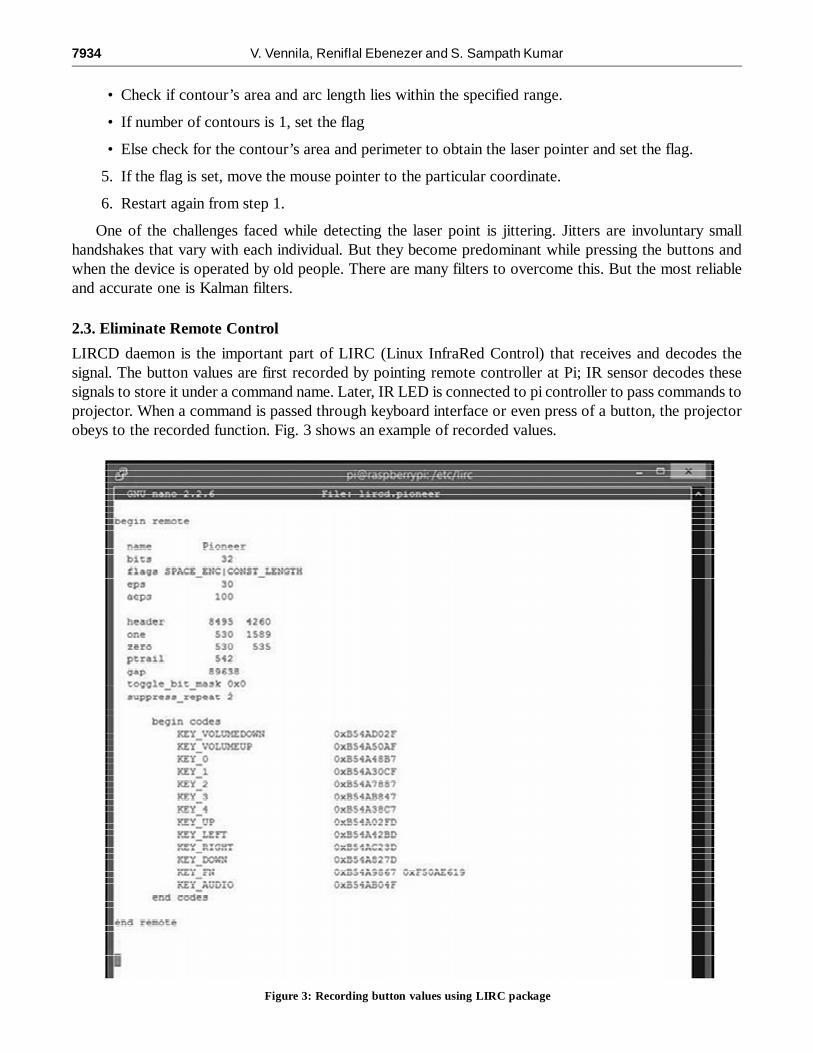
LIRCD daemon is the important part of LIRC (Linux InfraRed Control) that receives and decodes thesignal. The button values are first recorded by pointing remote controller at Pi; IR sensor decodes thesesignals to store it under a command name. Later, IR LED is connected to pi controller to pass commands toprojector. When a command is passed through keyboard interface or even press of a button, the projectorobeys to the recorded function. Fig. 3 shows an example of recorded values.
Figure 3: Recording button values using LIRC package

A User-Friendly Presentation System 7935
2.4. Automatic keystone adjustment
To correct a keystoned image, two methods are commonly used: (1) by using a corrected image for calibration,(2) by using the borders of the projector screen as calibration. Using borders of the screen is preferred sinceit is more accurate and less time consuming. But when the borders are absent the first method is used.
1. Initially the user has to take an image of the projection when it is in perfect rectangular form. Thisimage is used as the calibration unit. From the calibration image, the top and bottom edges arefound out. Their lengths are saved. When the keystone correction is required, the user will press theleft button in the LAMO main unit. This will cause an interrupt which will call the keystone serviceroutine. The following is the algorithm to process the calibration image.
2. The red image projected is then captured. The following pre-processes are executed.
• It is converted to grayscale.
• The grayscaled image is then thresholded.
3. The binary image after thresholding is then sent for corners detection.
• The corners are detected using the OpenCV function good Features To Track(). This will find atotal of 20 corners among which the four corners of our quadrilateral is present.
• From these 20 corners the top left and bottom right corners of the projection are filtered out.
• The product of the x and y coordinates of the found corners are calculated.
• The coordinates having the largest product are the coordinates of the top left corner.
• The coordinates having the smallest product are the coordinates of the bottom right corner.
3.1 This step is to find the remaining corners, that is the top right and bottom left corners.
• The thresholded image is flipped and sent again for corner detection. Steps from 3.1 to 3.3 arecarried out again.
3.2 Then the top left and bottom right corners are scaled to bottom left and top right corners respectivelyby subtracting the y coordinate value from the total height of the image.
3.3 After finding the four corners, the lengths of the top and bottom edges are found out by distanceformula.
4. These lengths are stored as the calibration lengths of top and bottom edges.
The following algorithm describes processing images in real time against the calibrated image:
4.1 Once the button is pressed, capture the red image projected by the projector.
4.2 It is converted to grayscale and is thresholded.
4.3 The binary image after thresholding is then sent for corners detection. Four corners of the quadrilateralto be correction are detected. Refer Step 3 of Processing the Calibration Image for detailed explanationof corner detection.
4.4 The top and bottom edge lengths are calculated by distance formula.
4.5 Now compare these new edge lengths with the calibration edge lengths and decide whether toincrease or decrease the keystone.
4.6 Then find the sum of the differences between the new top edge and bottom edges and calibrationtop and bottom edges respectively.
4.7 Divide the difference in edge lengths by a factor 0.4. This will give the number of times the keystonehas to be changed. This will bring the keystone closer to the corrected value.

7936 V. Vennila, Reniflal Ebenezer and S. Sampath Kumar
Then another frame is captured and steps 2 to 7 are executed. This will keep looping until the differencebetween the new edges and calibration edges are approximately zero.
The keystone correction service routine will capture the screen along with black borders. In this capturedframe, bottom edge and both the edges on sides are retrieved and angle between them are calculated. Theseangles are compared with the displayed red image to obtain the number of times the keystone has to bevaried. It is similar to previous algorithm except the formula for calculating keystone:
Difference between anglesKeystone =
0.2
3. RESULTS
Other parameters to assess this system are discussed below:
3.1. Accuracy
Accuracy is expressed with the difference between the laser pointer and actual position of cursor. Afterimplementing Kalman filter, its accuracy improved considerably.
3.2. Latency
From turning on the projector to adjusting the keystoned image it takes 15 seconds at an average andaround 30 seconds in worst situations. Besides, to move the cursor point to laser point position it hardlytakes a second.
3.3. Cost-efficiency
A wireless Logitech presenter which has a laser diode and used to change slides alone costs around Rs.5000. But the cost in making this hand held device that offers multi-features is estimated to be a little lessthan that as shown in Table 1.
Table 1Cost Details
S. No ITEMS COST (in Rs)
1. Raspberry pi board 25002. Bluetooth dongle 2003. MSP430 Launchpad 6604. CC2500 module 1200
TOTAL: 4 560
4. CONCLUSION
The image processing algorithm was derived to work in most of the test conditions using OpenCV and alsothe jitter problems in LASER point detection was eliminated. All the projector settings is now controlledthrough means of an IR LED driven by raspberry pi. One of the challenges in implementing this system wasto establish communication between various devices.
ACKNOWLEDGMENTS
We wish to thank, K.S.Govardhanam, L.Vairavan and A.H.Mohammed Shameel for supporting this project.We also extend our gratitude to Subashree, Sivashankar and Senthilnathan (Soliton Technologies) for helpfuladvice on our project.

A User-Friendly Presentation System 7937
REFERENCES
[1] Atul Chowdhary, Vivek Agrawal, Subhajit Karmakar, Sandip Sarkar, “Laser Actuated Presentation System”, in SahaNuclear Physics, pp. 2-6, 2000.
[2] Mamta Juneja, Parvinder Singh Sandhu, “Performance Evaluation of Edge Detection Techniques for Images in SpatialDomain”, International Journal of Computer Theory and Engineering, Vol. 1, No. 5, December, 2009.
[3] Matej Mesko, Stefan Toth, “Laser Spot Detection”, Journal of Information, Control and Management Systems, Vol. 11,2013.
[4] Nor Farizan Zakaria, Mohd. Asyraf Zulkifley, Mohd. Marzuki Mustafa, Rohana Abdul Karim, “A Review On Laser SpotDetection System Based On Image Processing Techniques”, Journal of Theoretical and Applied Information Technology,Vol.70 No.2, December 20, 2014.
[5] Ram Rajesh. J, Nagarjun. D , Arunachalam R. M and Aarthi. R, “Distance Transform Based Hand Gestures RecognitionFor Powerpoint Presentation Navigation”, Advanced Computing: An International Journal, Vol. 3, No. 3, May 2012.
[6] G.T. Shrivakshan, Dr. C. Chandrasekar, “A Comparison of various Edge Detection Techniques used in Image Processing”,IJCSI International Journal of Computer Science Issues, Vol. 9, Issue 5, No 1, September 2012.
[7] Jeremiah Aizeboje, “Exploring the Possibilities of Using a Laser Pointer as a Mouse”, Napier University, April, 2014.
[8] Lisa Seeman, David Dol, U.S. Patent 7 872 637 B2, Jan 18, 2011. [System and method for tracking a laser spot on aprojected computer screen image].
[9] Prof. Swati Shinde, Mayur Dhaigude, Prashant Dorage, Sachin Ghadge, Soumya. Dhingra, “Review on Laser BeamOperated Windows Operation”, International Journal of Engineering Research & Technology (IJERT), Vol. 3 Issue 3,March, 2014.
[10] Rahul Sukthankar, Robert G. Stockton, Matthew D. Mullin, “Self-Calibrating Camera-Assisted Presentation Interface”,International Conference on Control, Automation, Robotics and Vision (ICARCV), 2000.
[11] Xinpeng Huang and William Putnam, “Laser Pointer Mouse”, Introductory Digital Systems Laboratory, May 18, 2006.
[12] Evgeny Popovich and Zachi Karni, “Presenter Mouse LASER-Pointer Tracking System,” 2006.


![Interline Power Flow Controller - serialsjournals.comserialsjournals.com/serialjournalmanager/pdf/1481093126.pdf · have been applied for optimal placement and tuning of UPFC[8-11]](https://img.pdfslide.net/doc/110x75/5b00585c7f8b9a0c028c8fe5/interline-power-flow-controller-been-applied-for-optimal-placement-and-tuning.jpg)