Embed Size (px)
Citation preview

8/6/2019 A Van Cements in Digital
http://slidepdf.com/reader/full/a-van-cements-in-digital 1/105
ADVANCEMENTS IN
DIGITAL RADIOGRAPHY
Moderator :Mr. Ram Singh (Lecturer)
Deptt. of Radio-Diagnosis & ImagingPGIMER, Chandigarh-160012
Presented By:Debendra Prasad Gupta
M. Sc. Med. Tech. (Radiodiagnosis) – 1st Year Student
Deptt. of Radio-Diagnosis & Imaging
PGIMER, Chandigarh-160012
12th September, 2009
1

8/6/2019 A Van Cements in Digital
http://slidepdf.com/reader/full/a-van-cements-in-digital 2/105
DIGITAL RADIOGRAPHY:
Definition: -
It is defined as the image data acquired from
the numeric value i.e. in discrete binarydigits by use of computers .
Whereas in Conventional Radiography
information is represented in the analog or
continuous form rather than a discrete
fashion.2

8/6/2019 A Van Cements in Digital
http://slidepdf.com/reader/full/a-van-cements-in-digital 3/105
History: - In 1980 researchers at “ Fuji Laboratories”
developed an erasable X-ray imaging device
based on the x-ray excitation of a phosphor layer
and subsequent reading of the stored image data
with the help of infrared laser (i.e.
Photostimulable Luminescence).
Results showed that the imaging plate was moresensitive than conventional X-ray Film with
intensifying screens.
3

8/6/2019 A Van Cements in Digital
http://slidepdf.com/reader/full/a-van-cements-in-digital 4/105
Since the clinical use of x-rays in 1895, majority of radiographic examinations have been carried out by the
conventional method.
The beam is projected through the patient and the transmitted
beam, which has information about the body structures, ismade to strike the cassette containing the film and the
intensifying screens. This way the latent image is produced on
the film.
The latent image can be made visible and permanent by processing it with suitable chemicals.
This conventional method of obtaining radiographs has
dominated the field of radiography for many years. But now, it
has been realized that the FS system has its own limitations.
INTRODUCTION:
4
8/6/2019 A Van Cements in Digital
http://slidepdf.com/reader/full/a-van-cements-in-digital 5/105
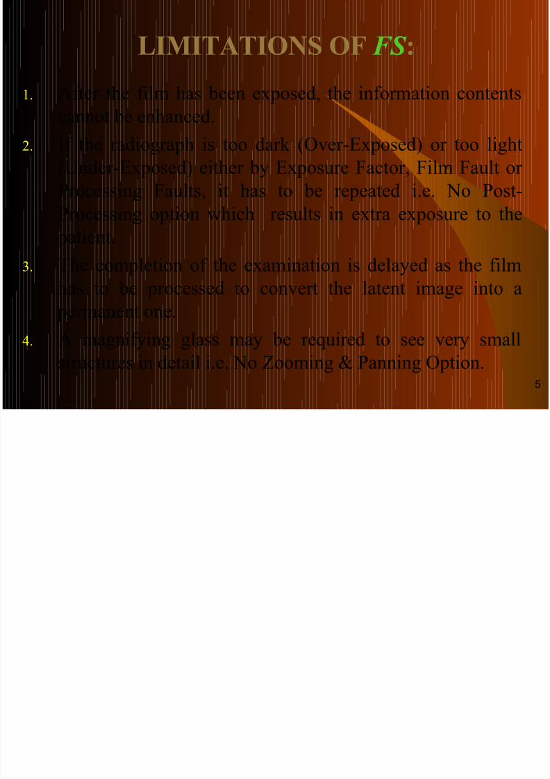
LIMITATIONS OF FS :
1. After the film has been exposed, the information contentscannot be enhanced.
2. If the radiograph is too dark (Over-Exposed) or too light
(Under-Exposed) either by Exposure Factor, Film Fault or
Processing Faults, it has to be repeated i.e. No Post-Processing option which results in extra exposure to the
patient.
3. The completion of the examination is delayed as the film
has to be processed to convert the latent image into a permanent one.
4. A magnifying glass may be required to see very small
structures in detail i.e. No Zooming & Panning Option.
5

8/6/2019 A Van Cements in Digital
http://slidepdf.com/reader/full/a-van-cements-in-digital 6/105
5. Copied radiographs are of inferior quality than original ones.
6. The film is a physical object and so it requires considerable morespace for storage i.e. Storage & Retrieval Cost.
7. Films can only be in one place at a time and they also get
deteriorated with passage of time.
8. Film can not be stored for longer time when required.
9. Dynamic range of x-ray film is limited (i.e. 0.2 – 3).
These limitations can be overcome by the incorporation of
computer technology into the diagnostic x-ray imaging.
With DR system conventional analog information is converted into
digital form, processing the digital data and displaying the image
on the monitor that surprisingly looks like a conventional image.
Cont…
6

8/6/2019 A Van Cements in Digital
http://slidepdf.com/reader/full/a-van-cements-in-digital 7/105
MILESTONE IN DIGITAL
RADIOGRAPHY:
Year Year Development: -Development: -
19801980 Scan Projection Radiography (SPR).Scan Projection Radiography (SPR).
19831983 Computed Radiography (CR), Storage Phosphors.Computed Radiography (CR), Storage Phosphors.
19901990 Charge-Coupled Device (CCD) Slot-Scan DirectCharge-Coupled Device (CCD) Slot-Scan Direct
Radiography (DR).Radiography (DR).
19941994 Selenium Drum Direct Radiography (DR).Selenium Drum Direct Radiography (DR).
19951995 Amorphous Silicon - Based–Cesium Iodide ( Scintillator )Amorphous Silicon - Based–Cesium Iodide ( Scintillator )
Flat-Panel Detector in Indirect DR.Flat-Panel Detector in Indirect DR.
19951995 Selenium-Based Flat-Panel Detector in Direct DR.Selenium-Based Flat-Panel Detector in Direct DR.19971997 Amorphous Silicon-Based - Gadolinium ( Scintillator ) Flat-Amorphous Silicon-Based - Gadolinium ( Scintillator ) Flat-
Panel Detector in Indirect DR.Panel Detector in Indirect DR.
20012001 Dynamic Flat-Panel Detector for Digital Fluoroscopy inDynamic Flat-Panel Detector for Digital Fluoroscopy in
DSA.DSA.7

8/6/2019 A Van Cements in Digital
http://slidepdf.com/reader/full/a-van-cements-in-digital 8/105
Digital Radiography (DR)
SPR
NaI – Scintillator
Photodiode
Indirect
Conversion
Storage Phosphor
Plate (IP)
BaFX:Eu+2
CR
Indirect Conversion Direct Conversion
DR
Photoconductor +
TFT (a:Se-DFPD)
Selenium Drum
Scintillator + Photodiode
(a:Si) + TFT (IFPD)
Scintillator + CCDCsI:Tl or CsI:Na &
Gd2O2S:Tb3+
According to the nature, design and function of the detector the
Digital radiography can be divided mainly in the following way: -
8
8/6/2019 A Van Cements in Digital
http://slidepdf.com/reader/full/a-van-cements-in-digital 9/105
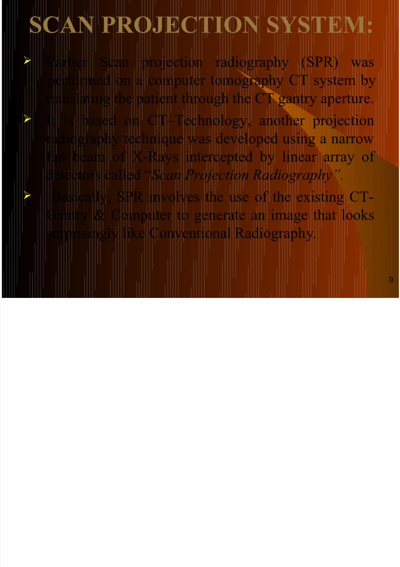
SCAN PROJECTION SYSTEM:
Earlier Scan projection radiography (SPR) was
performed on a computer tomography CT system by
translating the patient through the CT gantry aperture.
It is based on CT–Technology, another projection
radiography technique was developed using a narrowfan beam of X-Rays intercepted by linear array of
detectors called “Scan Projection Radiography”.
Basically, SPR involves the use of the existing CT-
Gantry & Computer to generate an image that looks
surprisingly like Conventional Radiography.
9

8/6/2019 A Van Cements in Digital
http://slidepdf.com/reader/full/a-van-cements-in-digital 10/105
The X-ray beam is shaped into a fan by
collimators that confine the beam to a 2-10
mm thickness through on arch of 300 – 450.
There are two collimators: -
1) The pre-patient collimators which shape the beam,
reduced scatter radiation & control patient dose.
2) The post-patient collimators which further reduce
the scatter radiation rejection.
SPR Cont…
10

8/6/2019 A Van Cements in Digital
http://slidepdf.com/reader/full/a-van-cements-in-digital 11/105
PRINCIPLE OF S.P.R.:
X-Ray beam after passing through patient isdetected by detector array. The signal have been image information of the body parts aretransferred to the computer where they get
digitized & processed to reconstruct theimage.
To obtain a complete image of the body part,
X-Ray tube & detector assembly remainsstationary & the patient is translated throughthe X-ray beam or alternatively patientremains stationary, while the X-Ray tube-detector assembly translates .
SPR Cont…
11

8/6/2019 A Van Cements in Digital
http://slidepdf.com/reader/full/a-van-cements-in-digital 12/105
COMPONENTS OF S.P.R. SYSTEM:
1. X-Ray Tube.
2. Pre-Patient Collimator.
3. Post-Patient Collimator.
4. Detector Array.
SPR Cont…
12

8/6/2019 A Van Cements in Digital
http://slidepdf.com/reader/full/a-van-cements-in-digital 13/105
X-RAY TUBE ASSEMBLY:
X-Ray tube of high heat loading capacityusually above 1 MHu is required because of long imaging time. Usually 20 – 50 cm
body part of patient is imaged at atranslation speed of 1 – 20 cm/s.
Two types of detector can be used: -
1. A Gas Filled.2. Scintillation Detectors couple with Solid
State Photodiode, i.e. CCD.
SPR Cont…
13
8/6/2019 A Van Cements in Digital
http://slidepdf.com/reader/full/a-van-cements-in-digital 14/105
Advantage: -
In SPR X-ray beam is collimated in a fan x-ray beam by Pre-
Patient & Post-Patient Collimators . i.e.: -
1. High Amount of Associated Scatter Rejection.
2. High Radiographic Image Contrast.3. High Dynamic Range (i.e. Low Contrast Detectibility).
4. Image Manipulation.
Disadvantages: -1. Scanning Time is More.
2. Poor Spatial Resolution &
3. More Radiation Dose to the patient.
SPR Cont…
14

8/6/2019 A Van Cements in Digital
http://slidepdf.com/reader/full/a-van-cements-in-digital 15/105
ADVANCEMENT:
At the present time, SPR is re-emerging with
some modification as a promising adjunct to
Digital Mammography Tomosynthesis
(DMT).
The purpose of all forms of Tomography is
to improve image contrast, and i.e. the goalof Digital Mammography Tomosynthesis
(DMT).
15

8/6/2019 A Van Cements in Digital
http://slidepdf.com/reader/full/a-van-cements-in-digital 16/105
COMPUTED RADIOGRAPHY:
Definition: - Digital way of doing General Radiography with
Conventional X-ray machines except ConventionalScreen/Film and dark room is known as Computed
Radiography.
Principle: -
It is based upon Photostimulated Luminescence in
which the radiographic data is captured from aconventional X-ray machine and processed the datadigitally to produce crisp and high qualityradiographic images.
16

8/6/2019 A Van Cements in Digital
http://slidepdf.com/reader/full/a-van-cements-in-digital 17/105
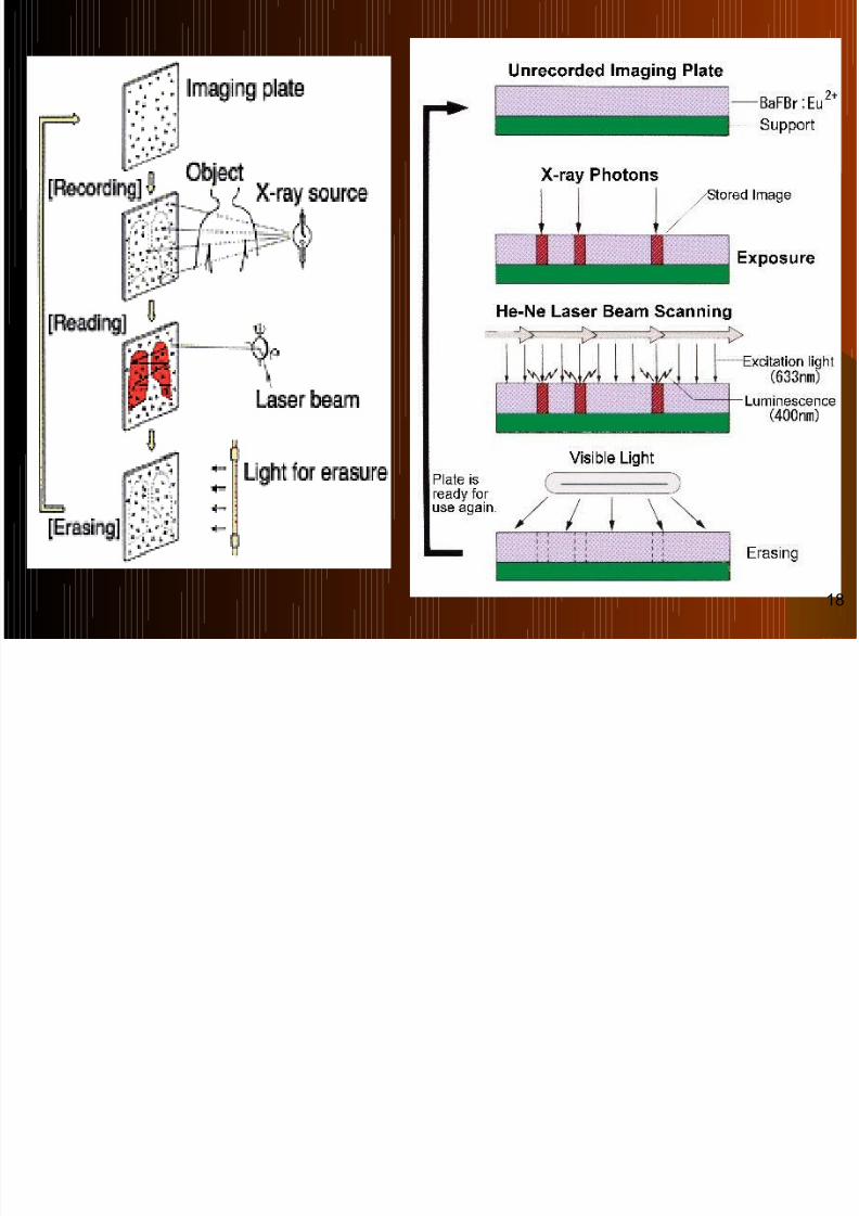
The CR Cassette is exposed with transmitted x-rays beam in a similar
fashion as the conventional cassette. The latent image is formed in the phosphor layer of the Imaging Plate in the
form of Electrical Charge .
Then the latent image is made visible on monitor by processing or scanned
and read that exposed imaging plate by a laser scanning device called
Image Reader. The output signal from the image reader is fed to an image array processor
where the digital gray – scale image is formed.
The digital image generated by the image reader is stored temporarily on a
local hard disk which is processed a/c to need and the resulting image can
be displayed either as soft (Video Display) copy on monitor or send itdirectly to laser printer that make hard (Film) copies of the digital image.
The digital image can then be stored on an optical or magnetic disk for long
term archiving or connected to the PACS through DICOM for Tele-
radiology.
Working:
17
8/6/2019 A Van Cements in Digital
http://slidepdf.com/reader/full/a-van-cements-in-digital 18/105
18

8/6/2019 A Van Cements in Digital
http://slidepdf.com/reader/full/a-van-cements-in-digital 19/105
19

8/6/2019 A Van Cements in Digital
http://slidepdf.com/reader/full/a-van-cements-in-digital 20/105
COMPONENTS OF THE C.R.
SYSTEM:
3.) Image Reader: -
4.) Image Processor: -
Cassette With Imaging Plate
2.) Image Recorder: -
1.) General X-ray Equipment: -
20
8/6/2019 A Van Cements in Digital
http://slidepdf.com/reader/full/a-van-cements-in-digital 21/105
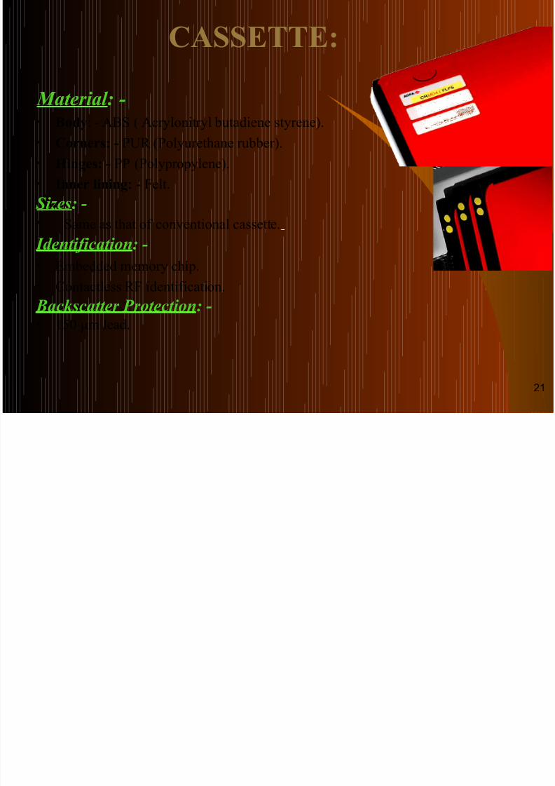
Material: -• Body: - ABS ( Acrylonitryl butadiene styrene).
• Corners: - PUR (Polyurethane rubber).
• Hinges: - PP (Polypropylene).
• Inner lining: - Felt.
Sizes: -• Same as that of conventional cassette.
Identification: -
• Embedded memory chip.
•
Contactless RF identification. Backscatter Protection: -• 150 μm lead.
CASSETTE:
21

8/6/2019 A Van Cements in Digital
http://slidepdf.com/reader/full/a-van-cements-in-digital 22/105
THE IMAGING PLATE ( IP ):
The Imaging Plate (IP) is also known as ComputedRadiography (CR) Plate or Storage Phosphor Screen
(SPS) or Photostimulable Phosphor (PSP) detector to
record the radiographic image in place of the
conventional film/screen cassette.
The imaging plate is housed in a rugged cassette &
appears similar to a screen/film cassette.
It is available in the same sizes as conventionalcassettes.
It is handled in the same manner as a screen/film
cassette.22
8/6/2019 A Van Cements in Digital
http://slidepdf.com/reader/full/a-van-cements-in-digital 23/105
It is not loaded & unloaded in a dark room. Rather, it is
handled in the manner of a screen/film daylight loader. A typical IP can store a latent image for a considerable
period of time. However, it will lose about 25% of the
stored signal b/w 10 min. to 8 hrs after an exposure
resulting in the loss of energy through spontaneous
phosphorescence.
It retains the image for 24 hours, but some degradation
may occur with passage of time. Imaging plate shows a linear response to the intensity
of x-ray exposure over a broad range.
Cont…
23

8/6/2019 A Van Cements in Digital
http://slidepdf.com/reader/full/a-van-cements-in-digital 24/105
CONSTRUCTION OF IMAGING
PLATE (IP):
Protective layer : -
- Fluorinated Polymer Material
Phosphor Layer: -- Ba FX: Eu +2 , 0.4mm thick.
Anti-halo Layer + Reflecting Layer
- Prevent laser light from passing through.
Base:-- PET- Polyethylene teraphtalate
Backing Layer: -
- Protects the base from damage &
reduces back scatter X-rays.
- 150 μm lead. 24

8/6/2019 A Van Cements in Digital
http://slidepdf.com/reader/full/a-van-cements-in-digital 25/105
THE IMAGING PLATE: A Protective Layer composed of “Fluorinated Polymer”
which make resistant to the abrasion, damaged & scratchescaused on the IP during storage and transfer.
The Phosphor Layer consist of a family of Photostimulable Phosphor crystals i.e. BrFX:Eu2+ where X can be any of halogens i.e. Chlorine (Cl), Bromine (Br) or Iodine (I) or an
arbitary mixture of them. A typical Phosphor Layer composed of about 85% - BaFBr
& 15% - BaFI , activated with a very small quantity of Europium (Eu) as activator in crystal.
This Europium activation procedure, also called doping,creates defects in the BaFBr crystals that allow electrons totrapped more efficiently i.e. increases more DQE of crystal.
Te Reflecting Layer lies b/w phosphor & base layer. which
prevents the reflection of light is also applied. 25

8/6/2019 A Van Cements in Digital
http://slidepdf.com/reader/full/a-van-cements-in-digital 26/105
The Base Layer composed of “ PolyethyleneTeraphtalate Resign” over which a layer of
photostimulable phosphor (Europium doped BariumFluoro Bromide crystals- BaFBr:Eu+2) is coated.
The next is Backing Layer composed of “Lead”which prevents the base from damage & reduces back scatter X-rays.
The last is the Bar-Code Label which contains thenumber assigned to the imaging plate.
This Bar-Code provides a mechanism for associatingeach imaging plate with Patient identification, Related examination & Positioning Information.
The imaging plate is flexible and less than 1mm
thick.
Cont…
26

8/6/2019 A Van Cements in Digital
http://slidepdf.com/reader/full/a-van-cements-in-digital 27/105
LATENT IMAGE FORMATION IN IP:
To prepare the imaging plat for an x-ray exposure, the
plate is exposed to the intense light to erase any
previous image. For X-ray imaging, the IP is placed in a cassette and is
used just like a film/screen cassette with standard
radiographic equipment. When exposed to X-ray, the Europium atoms in the
phosphor crystalline lattice are ionized & converted
from Eu2+ - Eu 3+ by librating a Valance Electron:
Eu2+ - X-ray Irradiation - Eu3+ + e-
These electron are raised to Higher Energy state in the
Conduction Band where they can moved through out
the crystal lattice. 27

8/6/2019 A Van Cements in Digital
http://slidepdf.com/reader/full/a-van-cements-in-digital 28/105
The presence of impurities (e.g Bromine) introduce energy
level in the Forbidden Zone called F – centre.
Once in the Conduction Band , the electron travel freelyuntil they trapped in the F – centre in the Metastable State
with an energy level slightly below that of Conduction
Band but higher than that of Valance Band .
The no. of trapped electron is proportional to the amountof X-ray absorbed locally.
The trapped electron in the form of metastable state
constitute the Latent Image.
Due to thermal motion electron will slowly be liberatedfrom traps, and the Latent Image should there for be read
without too much delay. At room temp, the image should, however, be readable up
to 8 hrs. after exposure.
Cont…
28

8/6/2019 A Van Cements in Digital
http://slidepdf.com/reader/full/a-van-cements-in-digital 29/105
LIFETIME OF THE IP: -
One of the major advantages of CR is that the imaging
plate is reusable and thousands of exposures can bemade on it.However, there are a number of factors that
may affect the lifetime of an imaging plate: - The plates are subjected to normal wear and tear from
scratches, scuffs, cracks, and contamination with dust
and dirt, which may interfere with the production of a
good image. The establishment of a well organised quality control
program will play an important role in assessing the
clinical quality of the imaging plate. This may easily
be carried out by artefact assessment and uniformity
evaluation across the plate.29

8/6/2019 A Van Cements in Digital
http://slidepdf.com/reader/full/a-van-cements-in-digital 30/105
Dust and dirt build up on CR phosphor plates, leading to image artifacts. Toavoid this, plates need cleaning atregular intervals.
Solvent: Ethanol - 99.7%.
Additives: Catanac SN (Cyastat SN50) - 0.3%.
Safety Precautions: -
- Highly flammable.
- Keep container closed.
- Keep away from sources of ignition.
IMAGING PLATE CLEANER:
30

8/6/2019 A Van Cements in Digital
http://slidepdf.com/reader/full/a-van-cements-in-digital 31/105
The CR image reader is alsoknown as Analog to Digital Converter (ADC).
Definition: -
It is a device which converts theContinuous Analog Image of Imaging Plate into the DigitalImage.
Construction: - It is consists of three parts: -
1. Mechanical Feature.
2. Optical Feature &
3. Computer Control.
IMAGE READER:
31
8/6/2019 A Van Cements in Digital
http://slidepdf.com/reader/full/a-van-cements-in-digital 32/105
When the CR cassette is inserted into the CR reader,the IP is removed and is fitted to a Precision drivemechanism.
The drive mechanism moves IP constantly, yet slowly(Slow Scan) along the long axis of IP.
Small fluctuations in velocity can result in bandingartifacts, so the motor drive must be absolutelyconstant.
When the IP is being transported in the slow scan
direction a deflection device such as rotating polygonor an oscillating mirror deflexed the laser beam back and forth across the IP.
These drive mechanisms are coupled so the laser beam is blanked during retrace.
1. MECHANICAL FEATURE:
32
8/6/2019 A Van Cements in Digital
http://slidepdf.com/reader/full/a-van-cements-in-digital 33/105
The error tolerance for this mechanism is fractions of
pixel. Image edges from a CR Reader that is out of
tolerance appear wavy. Another method is for the cassette to be placed in the
reader vertically with the IP withdrawn downward. As this occurs the cassettes is scanned by horizontal
laser. The IP barely leave the cassette, so, it is not subject
to roller damage. Further more, the scan is nearly always located atright angels to the direction of any grid lines, in thisway, aliasing artifacts are reduced.
Cont…
33

8/6/2019 A Van Cements in Digital
http://slidepdf.com/reader/full/a-van-cements-in-digital 34/105
The challenged to the CR Reader is to preciselyinterrogate each Metastable Electron of the latent
image in a precise fashion.
Components of the optical subsystem includes the
Laser, Beam Shaping Optics, Light Collecting Optics,Optical Filters & Photo Detector .
The laser is source of stimulating light; however, it
spreads as it travels to the rotating/oscillating reflector. This laser beam is focused on to the reflector by a lens
system that keeps the beam diameter small - less than
100 µm.
2. OPTICAL
FEATURES:
34
8/6/2019 A Van Cements in Digital
http://slidepdf.com/reader/full/a-van-cements-in-digital 35/105
As the laser beam is deflected across the IP, it changes
size & shape that is controlled by a Special BeamShaping Optics which keeps constant, the beam Size,
Shape, Speed & Intensity.
The laser beam scan s the IP in a transverse direction
while the IP is moved past the scanning beam.
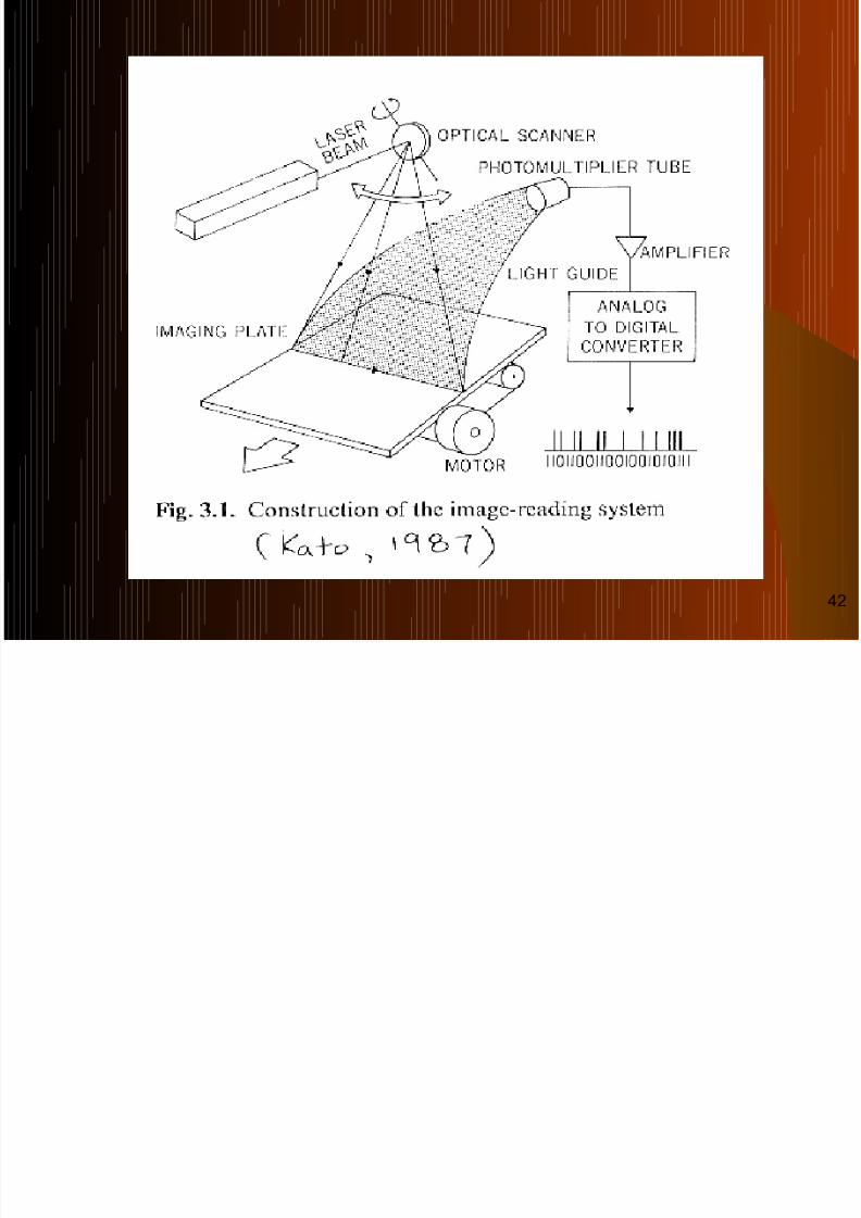
After scanning with laser beam, emitted light from the
IP is collected using a funnel like Fiber Optic
Collection assembly i.e. Light Guide and is directed atthe Photodetector or PMT or CCD where the light is
converted to an electrical signal which is
logarithmically amplified to an electric output signal.
Cont…
35

8/6/2019 A Van Cements in Digital
http://slidepdf.com/reader/full/a-van-cements-in-digital 36/105
This signal is converted by ADC into digital signalwhich is stored in a computer as a digital image matrix.
Before photo-detection occurs, the light is filtered with
the help of Optical Filter device embedded infront of
the Photodetector so that none of the long wavelength
stimulation light reaches the Photodetector & swamps
emitted lights.
In this case, emitted light is the signal & stimulatinglight is the Noise; therefore, Proper filtering improves
the Signal to Noise Ratio (SNR).
Cont…
36

8/6/2019 A Van Cements in Digital
http://slidepdf.com/reader/full/a-van-cements-in-digital 37/105
The Computer Control of a CR Reader provides: -- Signal Amplification.
- Signal Compression.
- Scanning Control.
- Analog to Digital Conversion &
- Image Buffering.
The out put of the Photodetector is a time varying analog signal
i.e. transmitted to a computer system that has multiple function. The time varying analog signal from the Photodetector is
processed for Amplitude, Scale & Compression that shapes thesignal before the final image is formed.
Then, the Analog Signal is Digitized by Digital to Analog
Converter (DAC), with attention paid to proper Sampling (time b/w samples) & Quantization (the value of each sample).
The Image Buffering occurs usually in a hard disc, this is a placewhere a completed image can be temporarily stored until it istransferred to a workstation for interpretation or for archival in
PACS.
3. COMPUTER CONTROL:
37
8/6/2019 A Van Cements in Digital
http://slidepdf.com/reader/full/a-van-cements-in-digital 38/105
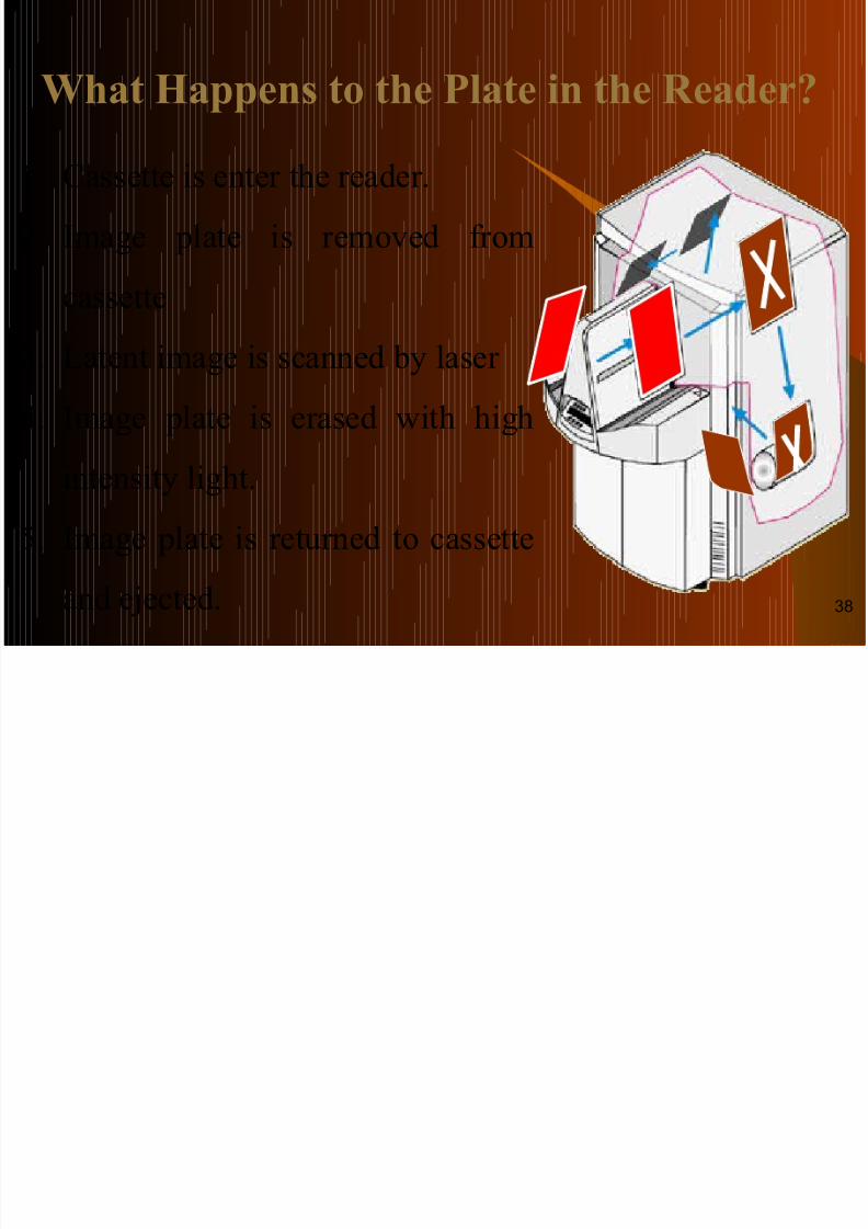
What Happens to the Plate in the Reader?
1. Cassette is enter the reader.
2. Image plate is removed from
cassette3. Latent image is scanned by laser
4. Image plate is erased with high
intensity light.
5. Image plate is returned to cassette
and ejected. 38

8/6/2019 A Van Cements in Digital
http://slidepdf.com/reader/full/a-van-cements-in-digital 39/105
After exposure the cassette is feeded into image reader system.
Where the cassette is opened automatically and the imaging plateis removed from the cassette inside the reader.
Then the IP is moved along its long axis and scanned sequentially(Horizontally) by a Monochromatic Infrared Laser Beam of
Helium-Neon (He-Ne) Gas or Solid State Laser of intensity ≈
633nm. The laser light stimulates the trapped electron moving them up to
the conduction band where they make their exit returning to thelower energy Valance Band.
This movement involves the transformation of Europium from the
Eu3+
- Eu2+
i.e. Metastable State to Ground State by emission of energy in the form of light ( Blue & Green) having a wavelengthlower than that of the stimulated laser light.
Eu3+ + e-→ (Influenced by IR Laser of 633 nm) → Eu2+ + hf (400 nm).
FUNCTION OR READING PROCESS:
39
C
8/6/2019 A Van Cements in Digital
http://slidepdf.com/reader/full/a-van-cements-in-digital 40/105
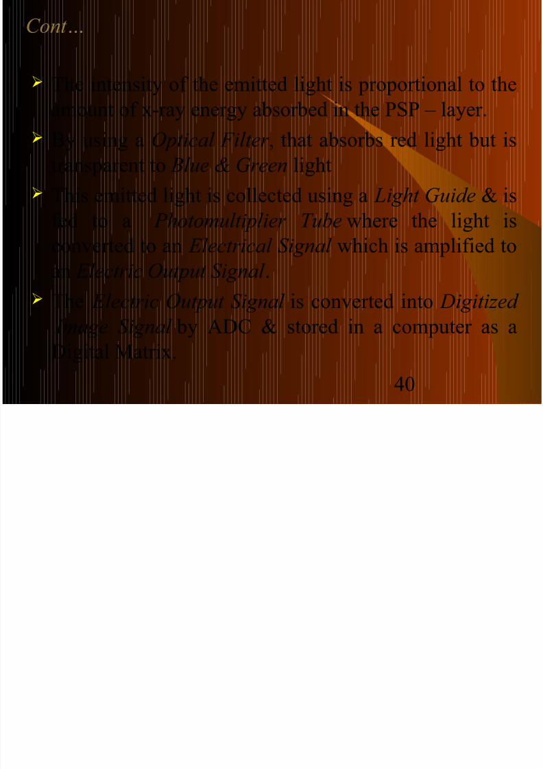
The intensity of the emitted light is proportional to the
amount of x-ray energy absorbed in the PSP – layer.
By using a Optical Filter , that absorbs red light but is
transparent to Blue & Green light
This emitted light is collected using a Light Guide & isfed to a Photomultiplier Tube where the light is
converted to an Electrical Signal which is amplified to
an Electric Output Signal .
The Electric Output Signal is converted into Digitized
Image Signal by ADC & stored in a computer as a
Digital Matrix.
Cont…
40
8/6/2019 A Van Cements in Digital
http://slidepdf.com/reader/full/a-van-cements-in-digital 41/105
8/6/2019 A Van Cements in Digital
http://slidepdf.com/reader/full/a-van-cements-in-digital 42/105
42
C
8/6/2019 A Van Cements in Digital
http://slidepdf.com/reader/full/a-van-cements-in-digital 43/105
Erasing Process: -
It is necessary to reuse the imaging plate again.
Because residual Latent Image electrons are still
trapped on higher energy level after readout.
If residual latent image remained, ghosting couldappear on subsequent use of the IP in the next exam.
This energy is erased after the readout process using a
high intensity white light from a bank of specially
designed Fluorescent Lamps source that flushes the
traps without reintroducing electron from the ground
energy level.
Cont…
43
8/6/2019 A Van Cements in Digital
http://slidepdf.com/reader/full/a-van-cements-in-digital 44/105
WORKSTATION:
Here Radiographic Technologist can be processed
the digital image in a variety of ways depending uponthe clinical application & the final image can berecorded as a hard copy through Multi Format Camera or Laser Imager . In the form of analog
image. Here digital data is stored on the hard disk of a work
station from where it can be processed, viewed, printed through or distributed via a local network to
peripheral stations. The work station provides a DICOM compliant output
which maybe directed to a laser Printer for hardcopies, or networked to other viewing stations or
archived in PACS for Teleradiology. 44

8/6/2019 A Van Cements in Digital
http://slidepdf.com/reader/full/a-van-cements-in-digital 45/105
ADVANTAGES OF C.R. SYSTEM:
No special equipment is required. No handling of Processing Chemicals.
The Exposure Latitude is wider i.e. High Dynamic Range(1:10,000) which leads to reduced rates of failed x-ray
exposure so in a single radiograph large densities variationcan be obtained.
Fewer Repeat examinations should be needed due toexposure factors because of the wide exposure Latitude.
The CR system are cassette based, they can easily beintegrated into existing radiographic devices are highlymobile so all types of Radiographic Examination i.e. Mobile, Portable (Bedside), Trauma, Dental Radiographyare possible with the C.R. system.
45
C t

8/6/2019 A Van Cements in Digital
http://slidepdf.com/reader/full/a-van-cements-in-digital 46/105
If a single Imaging Plate shows defects, it can easily bereplaced by the radiographer himself with no need for specialized equipment or service person.
The image displayed on the monitor can bemanipulated in a variety of ways: contrastenhancement, edge enhancement, black/white reversal,zooming & panning etc (i.e Post Processing).
The process of storing the images does not requireseparate rooms and is relatively easier.
Cost effective route to digital radiography. The acquired image can be transferred to many
monitors, different places for viewing to large no. of person.
Increased capability for consultation made possible byelectronic transmission of digital images through PACS& Teleradiology (i.e. networking system).
Cont…
46
8/6/2019 A Van Cements in Digital
http://slidepdf.com/reader/full/a-van-cements-in-digital 47/105
LIMITATIONS OF THE C.R. SYSTEM:
The technique is Time & Labor Intensive like FSR. Image reader takes time before the image can be displayed so
the time taken is same as that required for FSR.
Lesser spatial resolution as compared to conventional
radiography. Speed Class of 100-200 is similar to that of Medium Speed FSR
system so that radiation dose required is same or more than
FSR.
Radiological technologists receive no direct feedback on theaccuracy of their selection of exposure factors as the resultant
images are of consistent quality regardless of the exposure.
This may lead to undesirable and undetected over exposure to
the patient.47

8/6/2019 A Van Cements in Digital
http://slidepdf.com/reader/full/a-van-cements-in-digital 48/105
INNOVATIONS & NEWER
APPLICATIONS IN CR:
Some of the draw backs of CR system ,namely:
- Cassettes Handling.- Long Read Out Time of PSP Plates.
- Low DQE &
- Poor Resolution have been addressed by newer innovations &
technological advances.
48

8/6/2019 A Van Cements in Digital
http://slidepdf.com/reader/full/a-van-cements-in-digital 49/105
AUTOMATED CR SYSTEM WITH
FAST READOUT:
CR system efficiency has been recentlyimproved by reducing the readout time & byremoving the step of cassette handling.
Automated CR system achieve this by line – scan lasers & photodiode detectors that reducethe readout time of a PSP plate to less than 10s.
In these system there is no cassette handling,leading to totally automatic image dataacquisition.
49
8/6/2019 A Van Cements in Digital
http://slidepdf.com/reader/full/a-van-cements-in-digital 50/105
NEWER PHOSPHORS FOR IP :
Commercially available IP have unstructured phosphor like Rubidium Chloride (RbCl) or BaFX:Eu
These are scanned in a raster pattern.
A needle – shaped phosphor RbI, CsBr , has been
newly; introduced, e.g. Konica Minolta’s Regius 370
Upright DR & is considered more efficient due to its
structural configuration of crystals.
This crystal structure reduces lateral light diffusion because of the needle shaped configuration that acts aslight guide.
In addition the newer phosphors are more efficient withan increased DQE.
50
Cont

8/6/2019 A Van Cements in Digital
http://slidepdf.com/reader/full/a-van-cements-in-digital 51/105
Cont…
51
8/6/2019 A Van Cements in Digital
http://slidepdf.com/reader/full/a-van-cements-in-digital 52/105
MOBILE CR SYSTEM:
Bedside radiography of critically ill patients with conventional CR involves physical transport of the cassettes to the CR reader, often
located far away.
The situation gets worse as the no. of ‘portable ‘ films increase.
To save Labor, Time & Improve Workflow, portable compact CR system have been introduced in late 2007, with FugiFilm (FCR
Carbon XL CR Reader) & Carestream Health Inc (Pointof –
CAreCR-ITX 560) machines.
These system basically have a mobile X-ray unit with an integrated
CR reader.
So, they are easy to use & offer quick image availability in less than
25 sec.
52

8/6/2019 A Van Cements in Digital
http://slidepdf.com/reader/full/a-van-cements-in-digital 53/105
53

8/6/2019 A Van Cements in Digital
http://slidepdf.com/reader/full/a-van-cements-in-digital 54/105
DUAL-ENERGY IMAGING:
It is done by two methods: -
1.) Subtraction Technique &
2.) Double Expose Technique.
1.) Subtraction Technique: -
In this method, x-ray energies are separated by the insertionof a copper filter b/w two image plates which are then givena single exposure.
the low energy image is recorded on the front image plate &a high energy image is recorded on the back.
Owing to the difference in energy the absorption ratio of X-ray through bone & soft tissue will differ for the two images.
By subtracting these two images using weighted factors, bone or soft tissue detail can be selectively displayed.
54
Cont
8/6/2019 A Van Cements in Digital
http://slidepdf.com/reader/full/a-van-cements-in-digital 55/105
2.). Double Expose Technique: - In this method, by using a high & low KVp, two images arecreated in the two different image plates.
Soft tissue & bones can be separately depicted by thismethod.
Dual – energy technique are most effective when bothimages are acquired simultaneously.
Similar results are obtained with two exposure within a veryshort period of time.
Uses: - In Chest Radiography, particularly for the evaluation of
partially calcified nodules & pleural plaques.
Cont…
55

8/6/2019 A Van Cements in Digital
http://slidepdf.com/reader/full/a-van-cements-in-digital 56/105
AUTOMATIC IMAGE STICHING:
This is useful in determining precise measurement in lengthyanatomical regions like- whole spine, lower limbs or upper limb in a skeletal survey.
Now a days, the largest flat panel DR plates are available in 43X 43 cm.
Using these detectors, only a limited portion of the body partcan be imaged at a time in a single exposure, thus making thesedetectors inadequate for studying the whole spine or the entirelower limb.
To over come this problem, multiple sequential exposures at
different patient positions are acquired in a still patient. Automatic stitching is then performed to reconstruct a larger
composite image.
This special software enables pixel shift and overlap.56

8/6/2019 A Van Cements in Digital
http://slidepdf.com/reader/full/a-van-cements-in-digital 57/105
With the recent approval of the Clear View digitalmammography products, FUJIFILM Medical Systems USA
(Stamford, Conn) becomes the first vendor to offer a full-field
digital mammography (FFDM) system based on CR technology
in the United States.
CR for mammography uses imaging plates (IPs) made with
photostimulable phosphor to convert x-rays into digital
information. Existing glass, flat-panel FFDM systems rely on
solid-state detectors.
CR-BASED FFDM
57

8/6/2019 A Van Cements in Digital
http://slidepdf.com/reader/full/a-van-cements-in-digital 58/105
The CR Reader, the Clear View CSM, has a unique dual-side readingcapability that permits the capture of x-ray information from both sides of
the Imaging Plate (IP) simultaneously. The 50-µm laser excites the
phosphor, which has a thicker coating compared to standard CR IPs. Light
is emitted from both sides due to a clear base and is captured with dual
light guides.58

8/6/2019 A Van Cements in Digital
http://slidepdf.com/reader/full/a-van-cements-in-digital 59/105
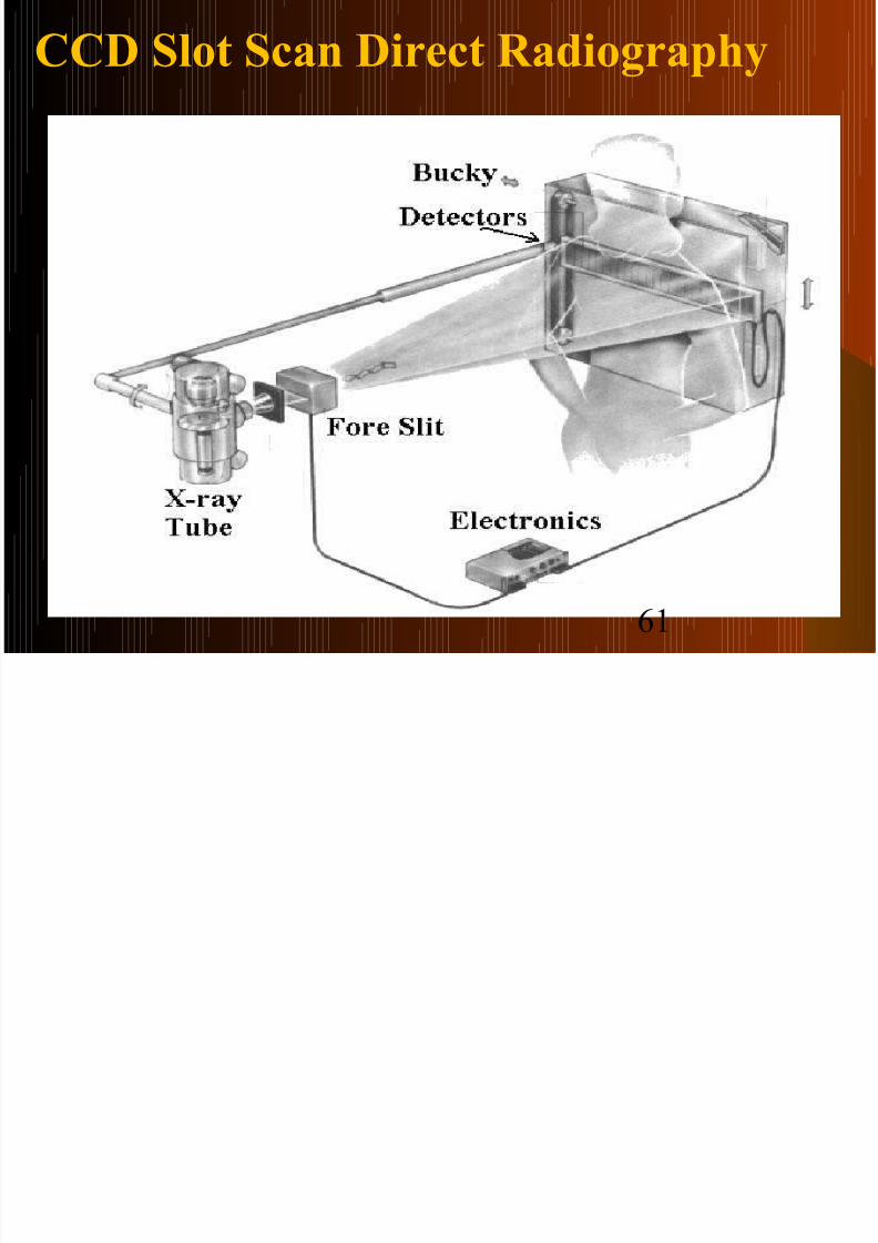
SLOT SCAN SYSTEM:
This system uses narrow fan beam X-ray of about 5mm & linear CCD array detector system.
It has mechanically linked x-ray tube & collimator
opposite the narrow CCD array with few rows of detector and scan along the long axis of the patient
anatomy.
It has two precisely aligned moving slit collimators,
one on either side of the patient. Due to which this system provides the ultimate in
scatter rejection & detector efficiency .
59
Cont

8/6/2019 A Van Cements in Digital
http://slidepdf.com/reader/full/a-van-cements-in-digital 60/105
Cont…
Thus use of a radiographic grid is not necessary,
significantly using the radiation dose. There are different possible movement of mechanical
linked system & patient couch movement. The exposure time to the patient is about 20 msec. &
readout process time takes about 1 - 3sec. Scan time depends on the area covered i.e. 2 – 30
seconds.
Because of the need for fixed installation, Slot ScanDR system is dedicated to Chest radiography,
Mammography, or Dental Radiography.
60
CCD Slot Scan Direct Radiography
8/6/2019 A Van Cements in Digital
http://slidepdf.com/reader/full/a-van-cements-in-digital 61/105
CCD Slot Scan Direct Radiography
61
ADVANTAGES:

8/6/2019 A Van Cements in Digital
http://slidepdf.com/reader/full/a-van-cements-in-digital 62/105
ADVANTAGES: Scatter radiation almost totally absent. No grid is required.
Radiation dose is reduced as grid no required. Detector efficiency is more with lower image noise. Longer & large anatomical regions are well covered.
DISADVANTAGES: High initial cost. Longer acquisition time due to narrow fan beam. So, requirement of equipment with high rating of
generator & X-ray tubes. i.e. high tube loading. Poor Spatial Resolution, due to Patient motion which
degrade image quality during scanning. It is a fixed modality method with bulky design. Bedside Radiography is not possible. 62
SELENIUM DRUM DR SYSTEM

8/6/2019 A Van Cements in Digital
http://slidepdf.com/reader/full/a-van-cements-in-digital 63/105
Rotating selenium-dotted drum, which has a positive electrical surface charge, is
exposed to x-rays. During exposure, a charge pattern proportional to that of theincident x-rays is generated on the drum surface and is recorded during rotation
by an analog-to-digital converter .
SELENIUM DRUM DR SYSTEM:
Advantage:-
It provide good image quality that issuperior to that provided by screen-film
or CR systems.
Disadvantage:-Because of their mechanical design,
selenium drum detectors are dedicatedfor chest stand systems only with no
mobility at all.
63
DIRECT RADIOGRAPHY (DR):
8/6/2019 A Van Cements in Digital
http://slidepdf.com/reader/full/a-van-cements-in-digital 64/105
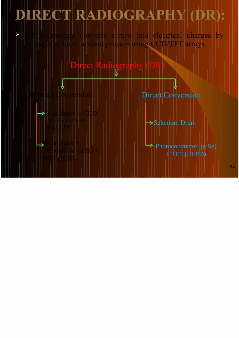
Indirect Conversion Direct Conversion
Direct Radiography (DR)
Photoconductor (a:Se)
+ TFT (DFPD)
Selenium Drum
Scintillator +
Photodiode (a:Si) +
TFT (IFPD)
Scintillator + CCDCsI:Tl or CsI:Na &
Gd2O2S:Tb3+
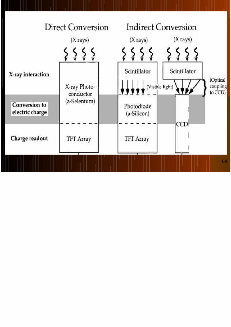
DIRECT RADIOGRAPHY (DR):
DR technology converts x-rays into electrical charges by
means of a direct readout process using CCD/TFT arrays.
64
INDIRECT DR:

8/6/2019 A Van Cements in Digital
http://slidepdf.com/reader/full/a-van-cements-in-digital 65/105
INDIRECT DR: In this case, X-ray energy is first converted into
light photons by an phosphor scintillator (CsI:Tl,Gd2o2S:Tb).
Then the light photons are converted in electric
charge by Photodiode Phosphor (a:Si).
The electric charge is converted in electrical
signal by CCD/TFT which is digitized by ADC in
digital signal & stored in computer.
The stored digital signal in computer is processedand converted in analog signal by DAC to see on
the monitor.
The whole process will take only 1.3 – 3 sec.65
Cont…

8/6/2019 A Van Cements in Digital
http://slidepdf.com/reader/full/a-van-cements-in-digital 66/105
Cont…
Convert X-rays into light photonConvert X-rays into light photonafter then electronic signals for after then electronic signals for
digital image formation.digital image formation.
Uses 3 step process : -Uses 3 step process : -
X –rays
Visible Light
Electronic Signals
Image formation
CsI:Tl, Gd2o2S:Tb
a:Si
TFT & ADC
66
DIRECT DR:
8/6/2019 A Van Cements in Digital
http://slidepdf.com/reader/full/a-van-cements-in-digital 67/105
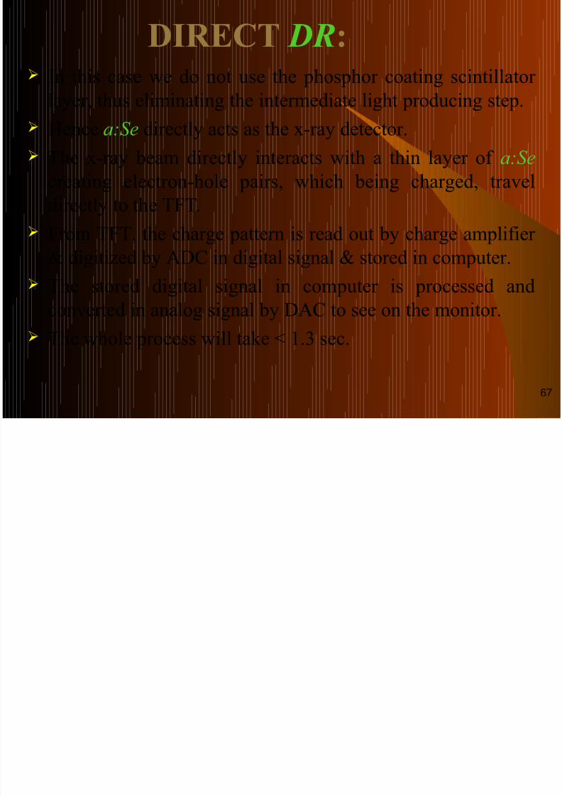
DIRECT DR: In this case we do not use the phosphor coating scintillator
layer, thus eliminating the intermediate light producing step. Hence a:Se directly acts as the x-ray detector.
The x-ray beam directly interacts with a thin layer of a:Se
creating electron-hole pairs, which being charged, travel
directly to the TFT. From TFT, the charge pattern is read out by charge amplifier
& digitized by ADC in digital signal & stored in computer.
The stored digital signal in computer is processed and
converted in analog signal by DAC to see on the monitor.
The whole process will take < 1.3 sec.
67
Cont…

8/6/2019 A Van Cements in Digital
http://slidepdf.com/reader/full/a-van-cements-in-digital 68/105
Convert X-rays into electronicsignals for digital image formation
Uses 3 step process : -Uses 3 step process : -
X –rays
Electronic Signals
Image formation
a:Si
TFT & ADC
68
8/6/2019 A Van Cements in Digital
http://slidepdf.com/reader/full/a-van-cements-in-digital 69/105
69
CONSTRUCTION & WORKING
8/6/2019 A Van Cements in Digital
http://slidepdf.com/reader/full/a-van-cements-in-digital 70/105
CONSTRUCTION & WORKING
OF FPD SYSTEM:
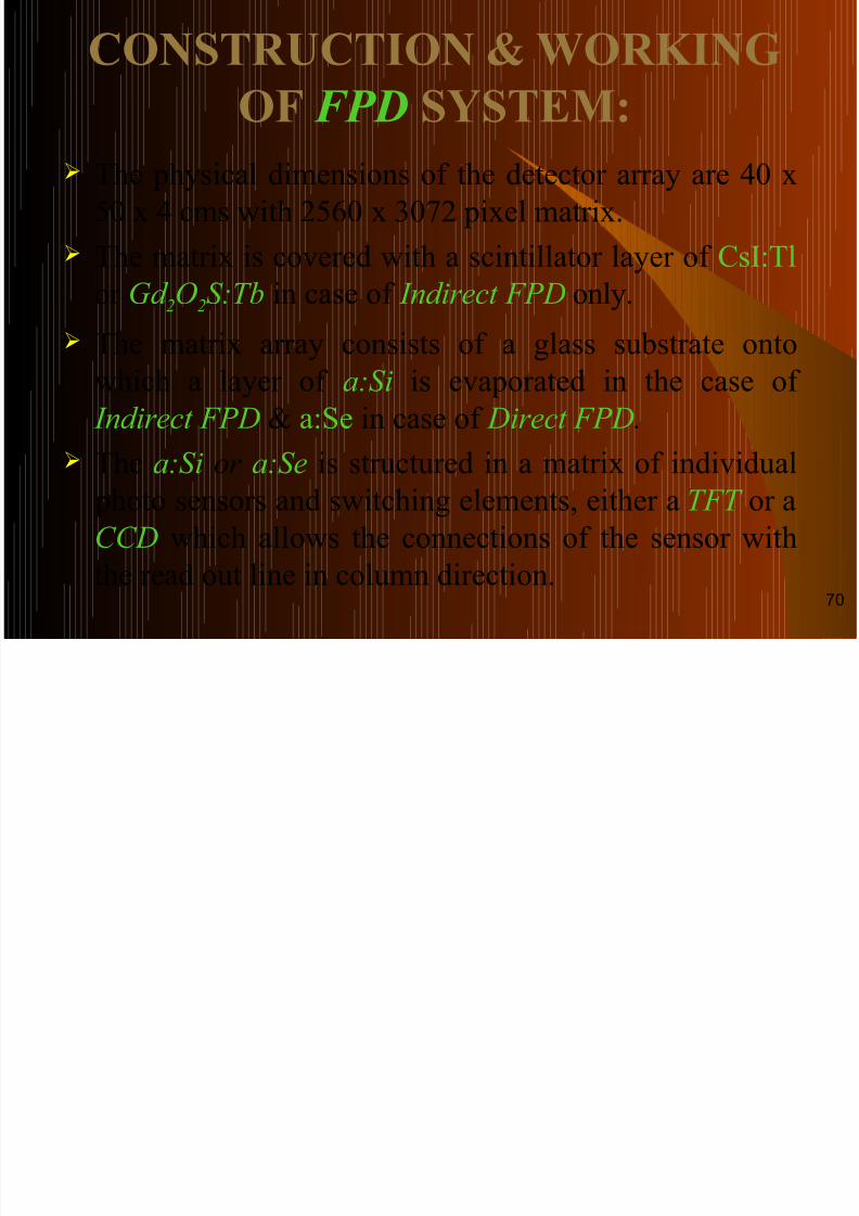
The physical dimensions of the detector array are 40 x
50 x 4 cms with 2560 x 3072 pixel matrix.
The matrix is covered with a scintillator layer of CsI:Tl
or Gd 2
O2
S:Tb in case of Indirect FPD only.
The matrix array consists of a glass substrate onto
which a layer of a:Si is evaporated in the case of
Indirect FPD & a:Se in case of Direct FPD.
The a:Si or a:Se is structured in a matrix of individual photo sensors and switching elements, either a TFT or a
CCD which allows the connections of the sensor with
the read out line in column direction.70
Cont…

8/6/2019 A Van Cements in Digital
http://slidepdf.com/reader/full/a-van-cements-in-digital 71/105
TFT or CCD are controlled via address lines in thehorizontal direction, in order to read out the singlecharge values of photodiodes.
These signals are multiplexed and converted into
digital signals by an A.D.C. inside the detector housing.
The 2-D digital image data is directly transferred tothe image processing computer via an optic fiber
link. So the image is available in digital form shortly
after the exposure has been made.
71
ADVANTAGES of DR SYSTEM:
8/6/2019 A Van Cements in Digital
http://slidepdf.com/reader/full/a-van-cements-in-digital 72/105
ADVANTAGES of DR SYSTEM: Increasing Workflow Efficiency, Saving Time & Labor.
Integrating high power X-ray system of 30 – 1000 KW Rating, veryShort Exposure Time , Eliminating Motion Blur.
Variable Speed Acquisition possible (speed class 100 – 800) dependingon acceptable SNR.
Most DR system have presets available for various anatomical studiesincluding optimized post processing e.g. chest, spine etc.
Automatic tube detector positioning for selected study.
Auto selection filter & Focal Spot Size a/c to the anatomical part.
Automatic tracking for easy positioning.
Immediate availability of image for Quality Check & Diagnosis.
The examination becomes quick as no cassettes have to be fetched fromthe storage area, taken to the examination site, or to the processing unitafter exposure.
Radiography as well as fluoroscopy can be performed.
Post processing can be done. 72
DISADVANTAGES OF DR

8/6/2019 A Van Cements in Digital
http://slidepdf.com/reader/full/a-van-cements-in-digital 73/105
DISADVANTAGES OF DR
SYSTEMS:
High initial cost.
Some radiographic view are difficult to obtain as
the detectors are generally not free to be placed in
any position. Careful handling is required due to fragile nature
of most detectors.
Due to its inflexibility, portable or ward
radiography is not possible.
Different equipment is required for different kinds
of work.73

8/6/2019 A Van Cements in Digital
http://slidepdf.com/reader/full/a-van-cements-in-digital 74/105
DIGITAL FLUOROSCOPY:
It provides Real Time Imaging of anatomic
structures. As maximum image detail is
required, so image brightness must be high. Image intensifier was developed to replace
the conventional fluoroscopic screen.
With the introduction of computer technology into fluoroscopy, digital images
with better detail can be obtained.
74

8/6/2019 A Van Cements in Digital
http://slidepdf.com/reader/full/a-van-cements-in-digital 75/105
EQUIPMENT:
D.F. requires the same fluoroscopy
equipment in addition to a computer, 2 video
monitors, and a more complex operatingconsole.
A high voltage generator.
A video system. A charge couple device.
75
8/6/2019 A Van Cements in Digital
http://slidepdf.com/reader/full/a-van-cements-in-digital 76/105
ADVANTAGES:
Less radiation dose as compared to the
I.I.T.V. system.
Better image quality.
76
DEVELOPMENTS IN D F :

8/6/2019 A Van Cements in Digital
http://slidepdf.com/reader/full/a-van-cements-in-digital 77/105
DEVELOPMENTS IN D.F. :
Flat panel detector system has replaced the I.I.T.V. system.
X-rays passing through the patient are converted into
electrical signals by the F.P.D. These are then passed
through the amplifier and ADC where they are converted
into digital signals. The digital image data is directly transferred to an image
storage PC via an optic fiber link at the rate of 30 f/s
This system permits high speed digital image acquisition, processing and display.
Images are of excellent resolution.
77
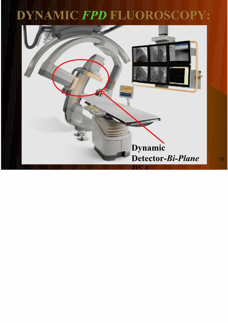
DYNAMIC FPD FLUOROSCOPY:
8/6/2019 A Van Cements in Digital
http://slidepdf.com/reader/full/a-van-cements-in-digital 78/105
Dynamic
Detector- Bi-Plane
DYNAMIC FPD FLUOROSCOPY:
78
INNOVATIONS & NEWER

8/6/2019 A Van Cements in Digital
http://slidepdf.com/reader/full/a-van-cements-in-digital 79/105
INNOVATIONS & NEWER
APPLICATIONS IN DR:
Digital Radiography is witnessing rapidinnovations in hardware as well as software
applications. Clinical utility & the true potential of these
applications will be understood better in the
years ahead.Few of the exciting applications are:
79

8/6/2019 A Van Cements in Digital
http://slidepdf.com/reader/full/a-van-cements-in-digital 80/105
Cont…
8/6/2019 A Van Cements in Digital
http://slidepdf.com/reader/full/a-van-cements-in-digital 81/105
Each absorbed X-ray photon results in a unit count
regardless of the photon energy.
As the electrical pulse generated is much higher than
the electronic noise, this type of DR system produce
images with high SNR. Uses: -
1) Mammography (Sectramicrodose).
2) In gaseous micros trip detectors for Biplane Whole Body Imaging in erect weight bearing position with
excellent result ( EOS of Biospace med).
81

8/6/2019 A Van Cements in Digital
http://slidepdf.com/reader/full/a-van-cements-in-digital 82/105
82
Ad
8/6/2019 A Van Cements in Digital
http://slidepdf.com/reader/full/a-van-cements-in-digital 83/105
Advantages: -
Radiation dose is reduced as grid is not required. High system DQE. High SNR due to minimal electronic noise. No ghost image (Previous exposure is residue). High contrast & detail resolution.
Disadvantages: -
Exposure time is long. Patients motion may degrade image quality. Requirement of equipment with high rating of generators
& X-ray tubes.83
DIGITAL TOMOSYNTHESIS

8/6/2019 A Van Cements in Digital
http://slidepdf.com/reader/full/a-van-cements-in-digital 84/105
DIGITAL TOMOSYNTHESIS:
In this technique multiple low dose exposure aregiven from various angles while the x-ray tubemoves in an arc & the detector remains stationary.
Multiple images with different focal zones are
possible to be created by addition of these low doseimages after pixel shift.
It emphasize contrast in a particular layer of a regionof body.
Generated images can be viewed singly or as a cineloop.
It is also considered to useful in Mammography,Chest, IVU studies.
84
DIGITAL MAMMOGRAPHY

8/6/2019 A Van Cements in Digital
http://slidepdf.com/reader/full/a-van-cements-in-digital 85/105
TOMOSYNTHESIS ( DMT ):
It is a recent advanced application of DM. In this technique, an area X-ray beam
interacts with the digitalmammographic image receptor, producing a digital mammogram.
This digital mammogram is repeatedseveral times at different angles.
Each images is available in digitalform & can be reconstructed as a 3DMatrix of values, each representing a
Voxel. With these digital data available, a
tomographic section can bereconstructed with enhanced imagecontrast at acceptable patient
radiation dose.85
MOBILE /PORTABLE DR:

8/6/2019 A Van Cements in Digital
http://slidepdf.com/reader/full/a-van-cements-in-digital 86/105
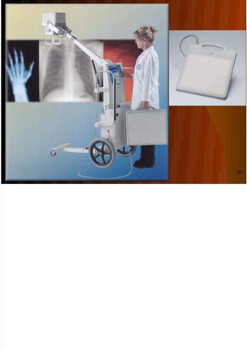
MOBILE /PORTABLE DR:
Now a days flat panel detector portable radiography
is also possible. This method was first invented by Canon.
The FPD are available in 17” X 17” with a cable for portable/mobile radiography.
As a general a FPD connected by a cable to a mobileor portable unit having a monitor.
The use of portable DR system hampered by thefragility of the FPDs & the high costs.
A portable DR system, when compared with an FSR system, avoids all problems related to theavailability, storage, transportation, disposed of films& chemicals. 86
8/6/2019 A Van Cements in Digital
http://slidepdf.com/reader/full/a-van-cements-in-digital 87/105
87
WIRELESS FPD

8/6/2019 A Van Cements in Digital
http://slidepdf.com/reader/full/a-van-cements-in-digital 88/105
WIRELESS FPDs:
With the introduction of the model Pixium 3543 from Thales,wireless portable DR system is now a reality.
After exposure, it wirelessly transfer image data to the DR system.
Alternatively the image data can be transferred to DR console
via an Ethernet cable. It has no cables & does not interfere with surrounding
machines. So, it is easy to handle as a CR cassettes.
Typically a 17” X 14” image size is made available within 3s.
It is particularly well suited for use with immobilized patients, in operating rooms, intensive care units, emergencysituations, and rooms for exams requiring difficult or unusualX-ray projections.
88
WIRELESS FPD SYSTEM:

8/6/2019 A Van Cements in Digital
http://slidepdf.com/reader/full/a-van-cements-in-digital 89/105
X-RayGenerator
Power
Supply
Pixium Portable
Docking Station
WiFi (or back-up cable)
Pixium Portable 3543
Ethernet
Cable
Acquisition
board
Ethernet
Board
RS 232Optical Fiber
Power supply
Pixium RAD 4600
PixRad software
PC
89
FLUOROSCOPY

8/6/2019 A Van Cements in Digital
http://slidepdf.com/reader/full/a-van-cements-in-digital 90/105
FLUOROSCOPY:
Real – time digital imaging in DR is possible withthe invention Pixium RF 4343, from Thales.
It facilitates high-quality radiography &
fluoroscopy (up to 30 images/sec.)
This fluoroscopy feature is use in Gastroenterology,
Urology & Vascular applications.
Newer FPDs like Pixium 4700 & Pixium 4800 from
Thales are used for Vascular & Cardiovascular DSAapplications by permitting low – dose fluoroscopy.
90
Integris Allura Integris Allura Flat DynamicFlat Dynamic
D f C diD t t f C di

8/6/2019 A Van Cements in Digital
http://slidepdf.com/reader/full/a-van-cements-in-digital 91/105
Detector for CardioDetector for Cardio
Scintillator Photodiode array Refresh light
91
IMAGE QUALITY PARAMETERS:IMAGE QUALITY PARAMETERS:

8/6/2019 A Van Cements in Digital
http://slidepdf.com/reader/full/a-van-cements-in-digital 92/105
IMAGE QUALITY PARAMETERS:IMAGE QUALITY PARAMETERS:
Pixel Size, Matrix & Detector Size.
Dynamic Range & Contrast.
Spatial Resolution. Limiting Spatial Resolution (LSR).
Signal to Noise Ratio (SNR). Modulation Transfer Function (MTF).
Detective Quantum Efficiency (DQE). 92
DYNAMIC RANGE & CONTRAST:
8/6/2019 A Van Cements in Digital
http://slidepdf.com/reader/full/a-van-cements-in-digital 93/105
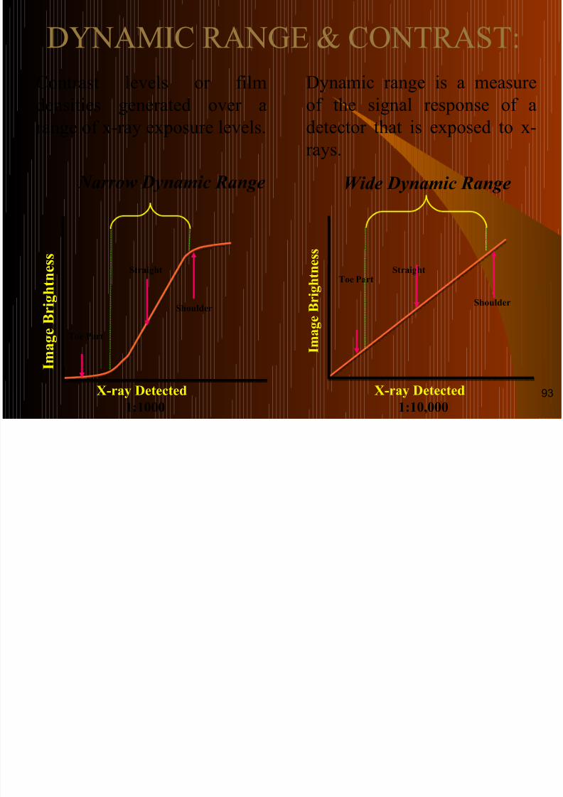
DYNAMIC RANGE & CONTRAST:
Contrast levels or film
densities generated over arange of x-ray exposure levels.
Dynamic range is a measure
of the signal response of adetector that is exposed to x-
rays.
Narrow Dynamic Range
Image
Brightness
Toe Part
Shoulder
Straight
X-ray Detected
1:1000
Wide Dynamic Range
Shoulder
StraightToe Part
X-ray Detected
1:10,000
ImageBrightne
ss
93
Cont…

8/6/2019 A Van Cements in Digital
http://slidepdf.com/reader/full/a-van-cements-in-digital 94/105
Film-Screen
Detector
Low Contrast
High Contrast
94
LIMITING SPATIAL RESOLUTION

8/6/2019 A Van Cements in Digital
http://slidepdf.com/reader/full/a-van-cements-in-digital 95/105
( LSR):
Reso lu t ion
Reso lu t ion
Spatial Resolution refers to the minimum resolvableseparation between high-contrast objects.
In Digital Detectors, Spatial Resolution is defined
and limited by the minimum Pixel Size.95
SIGNAL TO NOISE RATIO (SNR):
8/6/2019 A Van Cements in Digital
http://slidepdf.com/reader/full/a-van-cements-in-digital 96/105
Decreasing Noise
Increa
singC
ontras
t
High SNR Low SNR
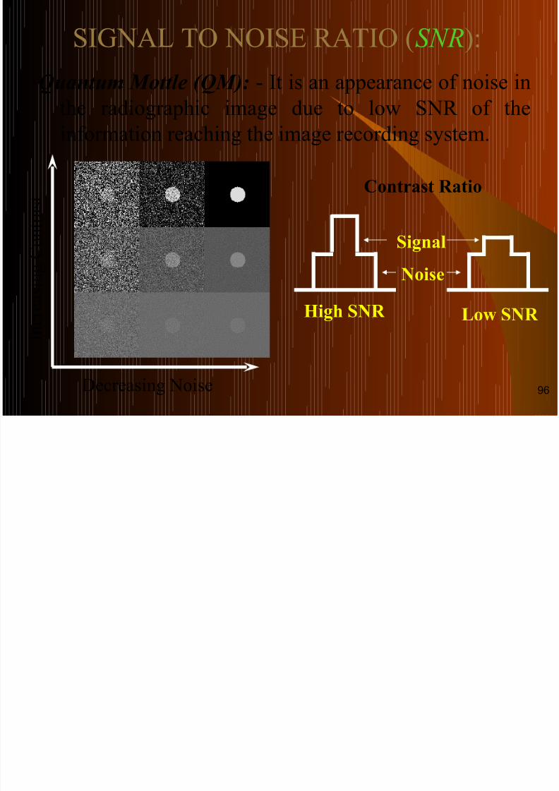
Noise
Signal
Contrast Ratio
Quantum Mottle (QM): - It is an appearance of noise in
the radiographic image due to low SNR of theinformation reaching the image recording system.
( )
96
IMPACT OF NOISE:
8/6/2019 A Van Cements in Digital
http://slidepdf.com/reader/full/a-van-cements-in-digital 97/105
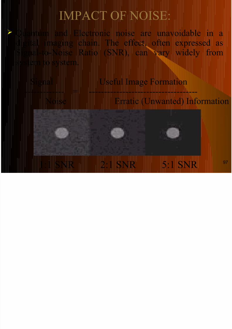
Quantum and Electronic noise are unavoidable in a
digital imaging chain. The effect, often expressed asSignal-to-Noise Ratio (SNR), can vary widely fromsystem to system.
Signal Useful Image Formation ------------- = ------------------------------------ Noise Erratic (Unwanted) Information
1:1 SNR 2:1 SNR 5:1 SNR97
MODULATION TRANSFER
8/6/2019 A Van Cements in Digital
http://slidepdf.com/reader/full/a-van-cements-in-digital 98/105
FUNCTION (MTF ).
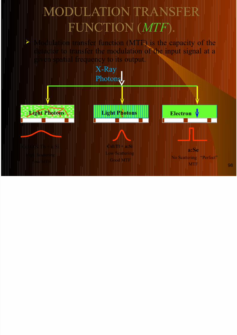
Modulation transfer function (MTF) is the capacity of thedetector to transfer the modulation of the input signal at agiven spatial frequency to its output.
Light Photons
Gd2O2S:Tb + a:Si
High Scattering
Low MTF
CsI:Tl + a:Si
Low Scattering
Good MTF
Electron
a:Se
No Scattering “Perfect”
MTF
Light Photons
X-Ray
Photons:
98
DEECTIVE QUANTUM EFFICIENCY (DQE):

8/6/2019 A Van Cements in Digital
http://slidepdf.com/reader/full/a-van-cements-in-digital 99/105
DEECTIVE QUANTUM EFFICIENCY ( DQE ):
Detective Quantum Efficiency (DQE) is one of thefundamental physical variables related to imagequality in radiography.
It is the % of X-ray absorbed by the image receptor.
It depends on: -- Radiation Exposure.
- Spatial Frequency.
- MTF.
- Detector Material.
- Quality of the radiation applied (Voltage & Current).
99
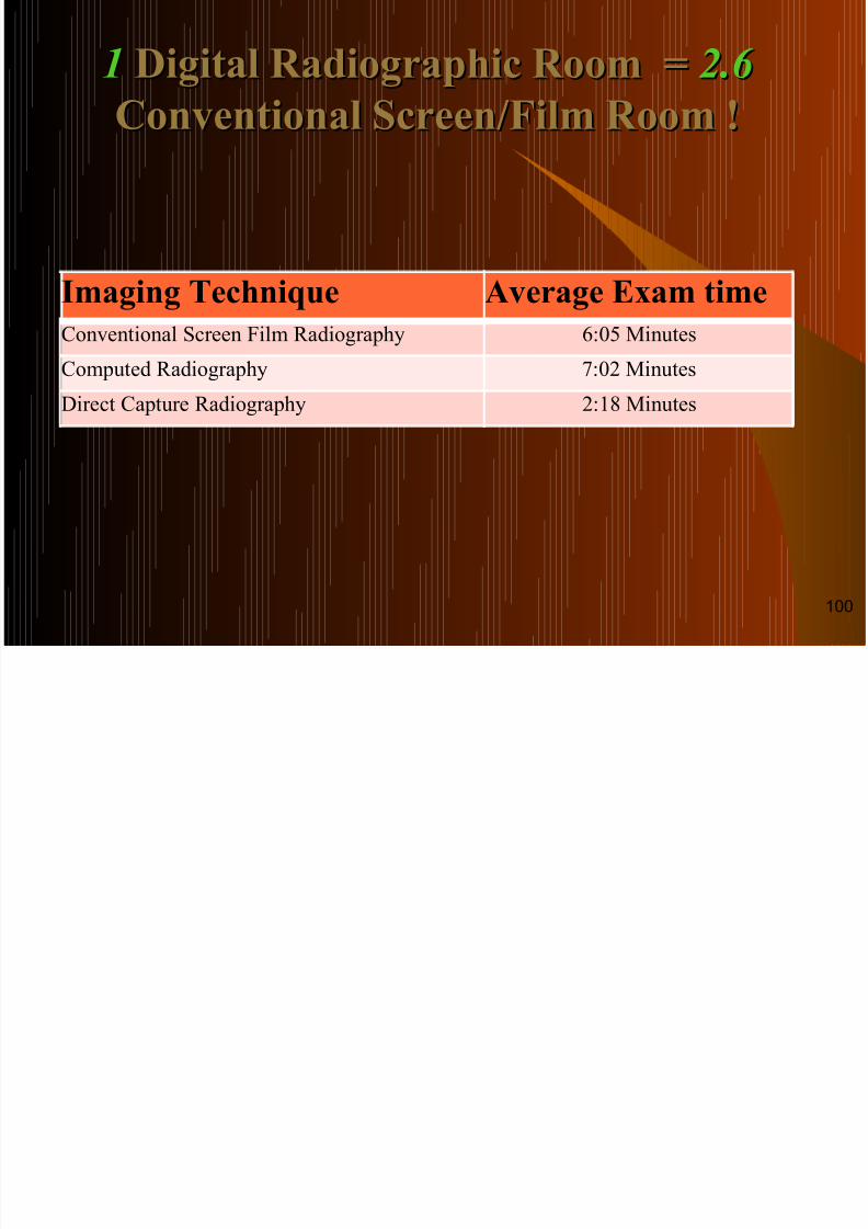
11 Digital Radiographic Room =Digital Radiographic Room = 2.62.6
8/6/2019 A Van Cements in Digital
http://slidepdf.com/reader/full/a-van-cements-in-digital 100/105
1 Digital Radiographic Room g g p 2.6
Conventional Screen/Film Room !Conventional Screen/Film Room !
Imaging Technique Average Exam time
Conventional Screen Film Radiography 6:05 Minutes
Computed Radiography 7:02 Minutes
Direct Capture Radiography 2:18 Minutes
100
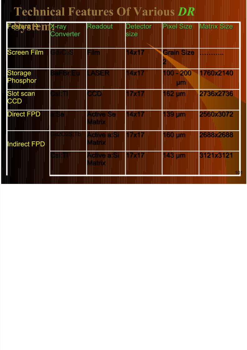
Technical Features Of Various DR
S t
8/6/2019 A Van Cements in Digital
http://slidepdf.com/reader/full/a-van-cements-in-digital 101/105
FeatureFeature X-rayX-rayConverter Converter
ReadoutReadout Detector Detector sizesize
Pixel SizePixel Size Matrix SizeMatrix Size
Screen FilmScreen Film Gd2O2S FilmFilm 14x1714x17 Grain SizeGrain Size
22
………………....
StorageStoragePhosphor Phosphor
BaFBr:EuBaFBr:Eu LASERLASER 14x1714x17 100 - 200100 - 200
µmµm
1760x21401760x2140
Slot scanSlot scanCCDCCD
CsI:TlCsI:Tl CCDCCD 17x1717x17 162 µm162 µm 2736x27362736x2736
Direct FPDDirect FPD a:Sea:Se Active SeActive SeMatrixMatrix
14x1714x17 139 µm139 µm 2560x30722560x3072
Indirect FPDIndirect FPDGd2O2S:Tb Active a:SiActive a:Si
MatrixMatrix17x1717x17 160 µm160 µm 2688x26882688x2688
CsI:TlCsI:Tl Active a:SiActive a:SiMatrixMatrix
17x1717x17 143 µm143 µm 3121x31213121x3121
System:
101
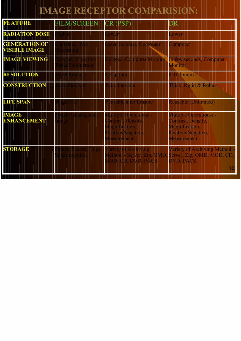
IMAGE RECEPTOR COMPARISION:
FEATURE FILM/SCREEN CR (PSP) DR
8/6/2019 A Van Cements in Digital
http://slidepdf.com/reader/full/a-van-cements-in-digital 102/105
FEATURE FILM/SCREEN CR (PSP) DR
RADIATION DOSE Higher Lower Lower
GENERATION OFVISIBLE IMAGE
Chemical, WetProcessing
Laser Scanner, Computer Computer
IMAGE VIEWING Delayed, View boxTransillumination
Delayed, Computer Monitor In few seconds, Computer Monitor
RESOLUTION 16-20 lp/mm 6-8 lp/mm 8-10 lp/mm
CONSTRUCTION Thin, Flexible Thin, Flexible Thick, Rigid & Robust
LIFE SPAN Single Use Reusable after Erasure Reusable (Unlimited)
IMAGEENHANCEMENT
Fixed UnchangeableImage
Multiple Operations: -Contrast, Density,Magnification,
Positive/Negative,Measurement
Multiple Operations: -Contrast, Density,Magnification,
Positive/Negative,Measurement
STORAGE Patient Record, HugeSpace required
Variety of ArchivingMethod: - Server, Zip, OMD,MOD, CD, DVD, PACS
Variety of Archiving Method: -Server, Zip, OMD, MOD, CD,DVD, PACS
102
IDEALIDEAL DR DR SYSTEM:SYSTEM:

8/6/2019 A Van Cements in Digital
http://slidepdf.com/reader/full/a-van-cements-in-digital 103/105
Physical Design: -
- Compatible in size with Film Cassette.- Immediate Readout.
- Robust.
- Cost Effective.
Image Capture: -- High Quantum efficiency.
- Low Dose.
Image Quality: -- Spatial & Contrast Resolution as goodas Film/Screen System.
- Wide Dynamic Range.
- DICOM Compatible.103
CONCLUSION:
8/6/2019 A Van Cements in Digital
http://slidepdf.com/reader/full/a-van-cements-in-digital 104/105
CONCLUSION: With the advent of computed radiography diagnostic
radiology is advancing towards a film less system.
The replacement of film by detectors and storage
devices eliminated several inherent drawbacks of
conventional radiography and decreases the radiationexposure to the patient and radiographer.
Very soon digital imaging will become more common
and affordable for all aspect of radiography.
With the development of Digital Radiography , theRadiographic Examination becomes more easy, handy
and less time consuming method with good quality of
image. 104

8/6/2019 A Van Cements in Digital
http://slidepdf.com/reader/full/a-van-cements-in-digital 105/105