Embed Size (px)
Citation preview

© Copyright 2017, IDT Inc. Analog Mixed Signal Systems1
Laurence McGarry, Marketing Director, IDT Wireless Power 31st Aug, 2017
A View From the Other Side of the ChasmSolving the Technological Challenges

© Copyright 2017, IDT Inc. Analog Mixed Signal Systems
Wireless Power:A View From The Other Side of the Chasm
• 200 Million wireless power ICs sold in 2016. (source: I.H.S)
• integrated into >25 smartphone • >20 smartwatches• >200 Wireless charging pads & 150 smartphone cases • >70 automotive models as a feature • Apple joins WPC Qi (Feb 2017)… • Asian Cellphone players moving rapidly

© Copyright 2017, IDT Inc. Analog Mixed Signal Systems
Content
• Magnetic Induction: Background & Basics• WPC Qi System Implementations• Key Considerations for Transmitter Design• Key Considerations for Receiver Design• Practical Implementations

© Copyright 2017, IDT Inc. Analog Mixed Signal Systems
Wireless Power Delivery Methods
4
- Electromagnetic Induction- Magnetic Induction- Direct Induction
- Magnetic Resonance- Resonant Transformer- Resonant Inductive Coupling
Magnetic field radiates outward- not shielded
- Capacitive Coupling- Radio Waves- Acoustic Waves
Adds cost and complexity. EMI and efficiency concerns
Practical only for very specialized applications. Many issues!!

© Copyright 2017, IDT Inc. Analog Mixed Signal Systems
Magnetic Induction Wireless PowerHow it works
5

© Copyright 2017, IDT Inc. Analog Mixed Signal Systems
Flux must be captured, ferrite directs furthest flux lines • We need to capture the flux with the Rx coil
inner diameter.- Too much flux isn’t always better. Typical Flux density in free space.
6
Low FluxCapture
High FluxCapture

© Copyright 2017, IDT Inc. Analog Mixed Signal Systems
The Basic Air Core Transformer Idea
• Coupling coefficient ‘k’ impacts mutual inductance M
- k influenced by turns ratio, ferrite area/thickness, and the space between the coils (k = 0.5 – 0.8 ideally)
7
V1 V2

© Copyright 2017, IDT Inc. Analog Mixed Signal Systems
Coil Coupling Possibilities
8
“Air” Gap
High ReluctanceAir Core Flux Path
Flux Lines in a very Low Reluctance Ferrite Core
TX
RX
• Not all flux generated by Tx coil is coupled into Rx coil, due to loosely coupled Tx and Rx. e.g. air gap, misalignment
• Flux not coupled into Rx coil can be described using leakage flux

© Copyright 2017, IDT Inc. Analog Mixed Signal Systems
Optimizations and Trade-offs
9

© Copyright 2017, IDT Inc. Analog Mixed Signal Systems
How to Get the Most Benefits from an MI Wireless Power System
• Rx coil must be close enough to Tx coil• Rx coil size should be larger or at least the similar
size of Tx coil size• Use of alignment tool (visual, mechanical, or magnetic
force) to best align Rx coil over Tx coil• Use of Litz wire to minimize coil AC resistance• Design proper coil gain to maintain optimal operation
condition
10

© Copyright 2017, IDT Inc. Analog Mixed Signal Systems
Coil Gain Design
11
Good Coil Gain Design Improper Coil Gain Design

© Copyright 2017, IDT Inc. Analog Mixed Signal Systems
The WPC Qi Advantage
• “Best of both worlds” solution using partiallyresonant magnetic induction
- Loosely coupled air-core transformer- Useable air-gap working distance of about 3mm – 8mm
(depending on transmitter type)
12
dB/dt
IPartially resonantTransmitter LC tank
Partially resonantReceiver LC tank

© Copyright 2017, IDT Inc. Analog Mixed Signal Systems
Simplified Designs Using Qi Systems
• Qi certified Transmitter designs are fully worked out, including detailed specification of all operational parameters and the physical coil design
• Receiver reference designs are similarly worked out, but in a way that enables the designer to choose/modify/make a Receiver coil that perfectly fits the design
• Because Qi is a robust interoperability standard, IC makers have invested to make single-chip solutions that completely eliminate most of the design work
13

© Copyright 2017, IDT Inc. Analog Mixed Signal Systems
WPC Transmitter Basic Topology
• Primary coil (Lp) + serial resonance capacitor (Cp)• DC-to-AC Inverter: e.g. half bridge (shown below) or full-bridge• Power level is controlled by changing transmitter operating frequency,
operating duty cycle, and/or bridge supply voltage.• Power is controlled by the Receiver which is the master of the transmitter • Multiple coil solutions function the same as single-coil with the “best” coil
selected by the transmitter before beginning interoperation with the Receiver
14
Power Conversion
Cp
Lp+
-
Half Bridge
Power Conversion
Multiplexer
Lp
+
-
Lm
Cm
Freq Freq
Single Coil Multiple CoilsSingle Coil Multiple Coils

© Copyright 2017, IDT Inc. Analog Mixed Signal Systems
WPC Receiver Basic Topology
• Secondary coil (Ls)• Serial resonance capacitor (Cs) for efficient power transfer• Parallel resonance capacitor (Cd) for required alternative
method to detect presence of a Receiver device by making 1MHz resonanceAC-to-DC Rectifier: full bridge (diode, or switched) + capacitor
• Output switch for disconnecting the load
15
Power Pickup Unit
Ls
Cs
Cd C
Load

© Copyright 2017, IDT Inc. Analog Mixed Signal Systems
WPC Communication (Modulation)
• Receiver modulates load by methodof Amplitude Shift Keying (ASK)
- Switch on/off modulation resistor (Rm), or- Switch on/off modulation capacitor (Cm)
• Transmitter demodulates Receiver information by- Sensing primary coil current (Ip) and/or- Sensing primary coil voltage (Vp)
• Transmitter modulates the frequency of the coil powersignal to send information to Receiver
- Receiver measures Tx coil drive frequency to demodulate Transmitter information
16
Note: Demodulated amplitude rangesfrom about 800mVpp to 10mVpp
Transmitter
Cp
Lp
+
-
Receiver
CdLs
Cs
C Rm
ModulationModulation
Cm
IpVp
Load
Power

© Copyright 2017, IDT Inc. Analog Mixed Signal Systems
WPC Communication: ASK Modulation
• Bit encoding scheme is defined by WPC • Each packet includes preamble, header, message, checksum• Each byte includes start bit (0), 8-bit data, parity, and stop. And
rate of bit is 2kHz. • This communication can be seen from Vrect (Rx), VSNS (Tx), ISNS
(Tx) and input current (Iin)• ASK communication might be corrupted due to coupling, permanent
magnet or repeating transient load.
17
VSNS (Tx)
ISNS (Tx)
Vrect (Rx)
Iin (Tx)
One Byte
Logic “0” and “1”

© Copyright 2017, IDT Inc. Analog Mixed Signal Systems
Tx Specification & Decision Drivers
• Decide target Rx Category: Wearable, Phone, Laptop, Automobile, Space Shuttle• Decide main input voltage (5V systems are common):
- Consider Rx Output Power (5W out à 5Vin; 10W out à 9Vin; 15W out; 12Vin)- Consult Specification for appropriate Tx and Resonance capacitance.
• Decide maximum power level to be delivered:- Select suitable DC power supply for Tx unit (voltage accuracy & current rating).
• Choose the pre-defined Qi Transmitter type that best matches the application- Choose from an IC vendor a chip solution that best meets the requirements for cost,
efficiency, EMC emissions, component count, etc.- Follow closely the IC vendor guidelines for system implementation
• Application Area: Smaller Products will need smaller solutions and more integration.• Active Area: Surface area available for charging.
18
From EVK to Production Ready Transmitter

© Copyright 2017, IDT Inc. Analog Mixed Signal Systems
Tx Power Control Methods• Frequency Control:
- Tx varies the operating frequency in order to adjust power, under IDT IC control.
• Duty Cycle Control- IDT Tx IC varies the Duty Cycle in order to adjust power (applies to
system once frequency is fixed).• Voltage Control (Buck fed system)
- Tx varies the VBRG voltage in order to adjust power.- External BUCK with output voltage under IC control.
19
LC P
ower
(W
)
Frequency (Hz), VBRIDGE(V), DUTY CYCLE(%)
LC Power (W) vs. Frequency (Hz), VBRIDGE (V), DUTY Cycle (%)Typical Power Available Characteristics
Tx Resonance

© Copyright 2017, IDT Inc. Analog Mixed Signal Systems
Tx Power Loss Mechanisms
20
TxCoilLoss57%
PCBLoss2%
MOSFETRdons14%
CsESR7%
Rsense3%
ChipIQ7%
MOSFETSwitching
5%
FET BodyDiodeLoss0%
InternalBuck5%
TxPowerLossDistributionVin=12V,Vout=12V,Iout=1.2A• Skin Effect
- Use wide copper planes for routing power paths and SWx nodes
• Friendly Metal Absorption- Eddy Current induced by the magnetic
field
• Switching Losses- Series Gate resistance, Gate Driver
output resistance
• Tx Coil Ferrite Magnetic Hysteresis• Current Sense Resistor value vs.
accuracy.- Influences : Tolerance (%), Tempco
(ppm/˚C), Power Rating (W), Package Size
- Must use Kelvin sense connections
© Copyright 2017, IDT Inc. Analog Mixed Signal Systems
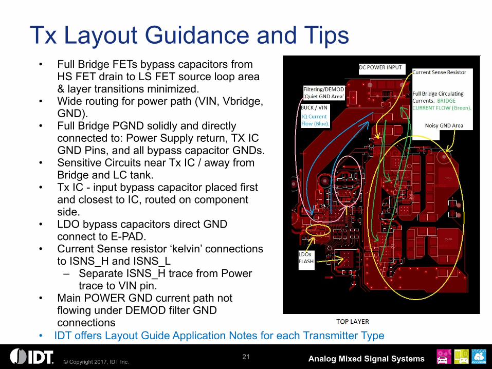
Tx Layout Guidance and Tips• Full Bridge FETs bypass capacitors from
HS FET drain to LS FET source loop area & layer transitions minimized.
• Wide routing for power path (VIN, Vbridge, GND).
• Full Bridge PGND solidly and directly connected to: Power Supply return, TX IC GND Pins, and all bypass capacitor GNDs.
• Sensitive Circuits near Tx IC / away from Bridge and LC tank.
• Tx IC - input bypass capacitor placed first and closest to IC, routed on component side.
• LDO bypass capacitors direct GND connect to E-PAD.
• Current Sense resistor ‘kelvin’ connections to ISNS_H and ISNS_L
– Separate ISNS_H trace from Power trace to VIN pin.
• Main POWER GND current path not flowing under DEMOD filter GND connections
21
• IDT offers Layout Guide Application Notes for each Transmitter Type

© Copyright 2017, IDT Inc. Analog Mixed Signal Systems
Rx Considerations
22
Zero Current Switching
SW node
Coil current
Full synchronous bridge rectifier: Rectifier bridge is controlled to be ON/OFF based on the current crossing on AC1 and AC2. Both top and bottom MOSFETs are switched OFF during current zero crossing to guarantee ZCS
0
0.05
0.1
0.15
0.2
0 0.2 0.4 0.6 0.8 1 1.2
Vrect-Vo
ut(V
)
Iout(A)
VrectHeadroomvsIout
Heavy load: Vrectheadroom is set very low to minimize the power loss on LDO.
Light load: Vect headroom vs Iout decreasing curve. Under no load conditions, Vrect target is high to mitigate the high step load response while does not dissipate too much power.

© Copyright 2017, IDT Inc. Analog Mixed Signal Systems
Rx Power Loss Mechanisms
• Rx coil has both copper wire loss (ACR) and ferrite loss (eddy current loss and hysteresis loss).
• Better coil wire: lower ACR with multi-strand to reduce the skin effect and proximity effect when height allows. PCB coils can be designed to reduce proximity loss.
• MOSFET switching and driver loss (includes Coss loss and gate driver loss) is very small due to ZCS
• MOSFET and LDO conduction loss is limited to the die size and cost.
23

© Copyright 2017, IDT Inc. Analog Mixed Signal Systems
Rx Layout Guidelines and Tips(IDT P9221 as example)
• Route the power connections wide and on the same side of the PCB as the P9221 (≥ 100mils).
• Use the layer under the P9221 side of the board as a solid ground plane.
24
• Connect all GND pins to the ground plane(s) using via-in-pads. Add a thermal tab for the J-row GND pins.
• Avoid unnecessary layer transitions of the AC power connections (LC node and the VRECT, AC1, AC2, and GND pins).
• Connect as much copper as possible to every pin of the P9221, including pins that do not carry high current.
• Use minimal trace-to-trace separation for all traces and planes connected to and within 10mm of the P9221-R.
• Use low ESR resonance capacitors (Cs/Cd) to decrease losses in the LC and AC1 current path.

© Copyright 2017, IDT Inc. Analog Mixed Signal Systems
Practical Implementations
25
Enabling more vendors to release their products quicker to the market
1-3W Solution 5W Solution 15W Solution
• Smart Watch Wearables • Health Monitors• Fitness Trackers • Portable Medical • Headphones and Earphone• Toys and Accessories
• Transmitter Infrastructure for Home, Office, Furniture
• After Market Automotive• PC Peripherals • Portable Medical • Wireless Speakers
• Transmitter Infrastructure for Home, Office, Furniture
• Fast Charge Cellular• Tablets• PC Peripherals

© Copyright 2017, IDT Inc. Analog Mixed Signal Systems
15W Reference Kit
26
Features• Complete Wireless Power Solution for 15W Applications
• WPC-1.2.3 compliant
• Transmitter MP-A2 Coil configuration– VIN=12V
• Low BOM cost and count• Up to 87% DC to DC efficiency
– P9242-R: VIN=12V– P9221-R: VOUT=12V & IOUT=1.25A
• Optional LED & audio indicator– Indicating power transfer
• Easy break-away coil for user customization
• Supported by extensive library of digital resources to ease design-in effort
0.05.0
10.015.020.025.030.035.040.045.050.055.060.065.070.075.080.085.090.095.0
0.1 0.2 0.3 0.4 0.5 0.6 0.7 0.8 0.9 1 1.1 1.2 1.3 1.4
Effic
ienc
y [
%]
OUTPUT CURRENT [A]
Efficiency vs. Output Load CurrentTx: P9242-R, VIN=12V; Rx: P9221-R , VOUT=12V, Gap=
3mm; Rx coil: Amotech; Tx Coil: Sunlord

© Copyright 2017, IDT Inc. Analog Mixed Signal Systems
Key Takeaways
• Wireless Power: on ‘the other side of the chasm’ and ready to enter mainstream adoption
• System designers converging around the WPC Qi specification
• Turnkey, reference designs 1-15W enable fast & easy copy/paste to evaluate and implement wireless power in a number of applications

© Copyright 2017, IDT Inc. Analog Mixed Signal Systems
Thank You Analog Mixed Signal Product Leadership in Growth Markets


![[Codientu.org] 3 EE462L Diode Bridge Rectifier](https://img.pdfslide.net/doc/110x75/577ccd321a28ab9e788bc2dd/codientuorg-3-ee462l-diode-bridge-rectifier.jpg)