Embed Size (px)
Citation preview

Rochester Institute of Technology Rochester Institute of Technology
RIT Scholar Works RIT Scholar Works
Theses
8-2015
A Wireless Communication Platform for MEMS Sensors A Wireless Communication Platform for MEMS Sensors
Chen Chen
Follow this and additional works at: https://scholarworks.rit.edu/theses
Recommended Citation Recommended Citation Chen, Chen, "A Wireless Communication Platform for MEMS Sensors" (2015). Thesis. Rochester Institute of Technology. Accessed from
This Thesis is brought to you for free and open access by RIT Scholar Works. It has been accepted for inclusion in Theses by an authorized administrator of RIT Scholar Works. For more information, please contact [email protected].
A Wireless Communication Platform for
MEMS Sensors
By
Chen Chen
A Thesis Submitted in Partial Fulfillment of the Requirements for the Degree of
MASTER OF SCIENCE in Electrical Engineering
DEPARTMENT OF ELECTRICAL AND MICROELECTRONIC ENGINEERING
KATE GLEASON COLLEGE OF ENGINEERING
ROCHESTER INSTITUTE OF TECHNOLOGY
ROCHESTER, NEW YORK
AUGUST, 2015
Committee Approval:
PROF. ______________________________________ Date __________
(Thesis Advisor, Dr. Lynn Fuller)
PROF. ______________________________________ Date __________
(Committee Member, Dr. Robert Pearson)
PROF. ______________________________________ Date __________
(Committee Member, Dr. Ivan Puchades)
PROF. ______________________________________ Date __________
(Department Head, Dr. Sohail Dianat)

I
Abstract
Wireless measurement systems combining current advanced information collection,
processing and wireless communication technology, have been applied to information
measurement in special occasions. As a short range wireless communication technology,
bluetooth is low cost, stable, and low power. Bluetooth technology is used in monitoring
and wireless control system widely.
ArduinoBT is the bluetooth version of the general Arduino board, which is open source
and convenient as a wireless development tool.
This thesis presents a hardware and software experimental wireless platform for the
application of multiple kinds of MEMS sensors. By the combination of ArduinoBT and
signal conditioning circuit, different types of sensors can work at the same time and the
outputs can all be sent to host computer by Bluetooth.

II
Table of Contents
Abstract ........................................................................................................................... I
List of Figures .............................................................................................................. III
List of Tables ................................................................................................................ IV
Chapter 1 Introduction ................................................................................................. 1
Chapter 2 Introduction of ArduinoBT .......................................................................... 3
Chapter 3 Design of System ...................................................................................... 11
3.1 Introduction of Sensors .................................................................................... 12
3.2 Circuit Design .................................................................................................. 17
3.3 Multiplexer ...................................................................................................... 22
Chapter 4 Experimental Procedure............................................................................. 24
4.1 Bluetooth Connection ...................................................................................... 24
4.2 PCB Design ..................................................................................................... 28
4.3 Data Collection and Calculation ....................................................................... 30
Chapter 5 Results Analysis ........................................................................................ 33
5.1 Noise ............................................................................................................ 33
5.2 Calibration ................................................................................................... 35
5.3 Low Power Consumption ............................................................................. 35
Chapter 6 Conclusions ............................................................................................... 37
Reference ..................................................................................................................... 38
Appendix A Main Code ............................................................................................. 40
Appendix B Changing Name of Arduino Code .......................................................... 44
Appendix C Sleep and External Wake Up Code ......................................................... 46
Appendix D WT11 Sleep and Wake Up Code ............................................................ 50
Appendix E ArduinoBT 06 ........................................................................................ 56

III
List of Figures
Fig. 2.1 ArduinoBT Board…………………………………………………………...……4
Fig. 3.1 System Architecture………………………………………………………….…..1
Fig. 3.2 BPW46 Photo Diode……………………………………………………………12
Fig. 3.3 Reverse Light Current vs. Illuminance…………………………………………13
Fig. 3.4 1N4148 Diode…………………………………………………………………..14
Fig. 3.5 Forward Voltage vs Ambient Temperature……………………………………..15
Fig. 3.6 HCH-1000 series humidity sensor……………………………………………...15
Fig. 3.7 Relative Humidity vs Capacitance………………...……………………………16
Fig. 3.8 Signal Conditioning Circuit……………………….……………………………17
Fig. 3.9 PCB and ArduinoBT……………………………………………………………18
Fig. 3.10 Current Input Conditioning Circuit……………………………………………19
Fig. 3.11 Voltage Input Conditioning Circuit……………………………………………20
Fig. 3.12 Capacitor Input Conditioning Circuit…………………………………………21
Fig. 4.1 BTD211 bluetooth micro USB adapter…………………………………………23
Fig. 4.2 Change Bluetooth settings…………………………...…………………………26
Fig. 4.3 Show Bluetooth Icon In the Notification Area…………………………………26
Fig. 4.4 Top Layer of PCB………………………………………………………………27
Fig. 4.5 Bottom Layer of PCB…………………………………..………………………27
Fig. 4.6 PCB Layout……………………………………………..………………………28
Fig. 5.1 Noise……………………………………………………………………………32
Fig. 5.2 De-noise………………………………………………………………………...3

IV
List of Tables
Table 2.1 Summary of ArduinoBT……………………………………………………….5
Table 3.1 Truth Table………………………………………………………………….…22
Table 4.1 PCB Component Values………………………………………………………29
Table 5.1 Feature Estimate………………………………………………………………35

1
Chapter 1
Introduction
Bluetooth is a wireless technology standard for exchanging data over short distances
(using short-wavelength radio transmissions in the ISM band from 2400–2480 MHz)
from fixed and mobile devices, creating personal area networks (PANs) with high levels
of security. It is a simple and convenient way for short range wireless communication,
which has been applied all over the world. Bluetooth has many advantages as portable,
wireless, low power, low cost, security, stable and automatic connection. Bluetooth is
widely applied to personal work or business application, automobile industry, intelligent
home appliances, healthcare applications[1], traffic service[2], environmental monitoring,
geological work, and so on.
Wireless sensors are standard measurement devices equipped with transmitters to convert
signals from sensors into a radio transmission. The radio signal is interpreted by a
receiver which then converts the wireless signal to a serial data stream for analysis via
computer software.

2
The ArduinoBT is an Arduino board with built-in bluetooth module, allowing for
wireless communication. ArduinoBT collect analog signals from sensors and converted
them to digital values. By sending digital signals to the host computer, radio noise cannot
get involved into the signals easily.

3
Chapter 2
Introduction of ArduinoBT
Generally, a computer includes following parts: central processing unit (CPU, for
calculation and control), random access memory (RAM, for data storage), read only
memory (ROM, for program storage), and input/output peripheral (serial port, parallel
output, etc.). On a personal computer, those parts are divided as several separated
electronic chips that are mounted on motherboard. In comparison, a microcontroller is a
small computer on a single integrated circuit that includes all those parts. Besides that,
some microcontrollers also have other parts like A/D converter and D/A converter.
ArduinoBT is a hardware platform base on microcontroller and open source code that
can be used as a tool to interact with and control the real physical world. Compare to
many other microcontroller like Parallax Basic Stamp, Netmedia’s BX-24, or Phidgets,
Arduino is more economical, cross-platform, open source and extensible
software/hardware.

4
Fig. 2.1 ArduinoBT Board [3]
ArduinoBT is a microcontroller board that supplied with the ATmega328[4] and the
Bluegiga WT11 bluetooth module[5]. It supports wireless serial communication over
bluetooth. It has 14 digital input/output pins (of which 6 can be used as PWM outputs
and pin 7 can be used to reset the WT11 bluetooth module), 6 analog inputs, a 16 MHz
crystal oscillator, screw terminals for power, an ICSP header, and a reset button. It
contains everything needed to support the microcontroller and can be programmed
wireless over the bluetooth connection.

5
Table 2.1 Summary of ArduinoBT[3]
Microcontroller ATmega328
Operating Voltage 5V
Input Voltage 2.5-12 V
Digital I/O Pins 14 (of which 6 provide PWM output)
Analog Input Pins 6
DC Current per I/O Pin 40 mA
DC Current for 3.3V Pin 500 mA (with a 1.5A capable power source)
DC Current for 5V Pin 1000 mA (with a 1.5A capable power source)
Flash Memory 32 KB (of which 2 KB used by bootloader)
SRAM 2 KB
EEPROM 1 KB
Clock Speed 16 MHz
BT Module 2.1 WT11i-A-AI4
Power
The ArduinoBT can be powered via the V+ and GND screw terminals. The board
contains a DC-DC convector that allows it to be powered with as little as 1.2V, but a

6
maximum of 5.5V. Higher voltages or reversed polarity in the power supply will damage
or destroy the board.
Power Pins:
9V: The input voltage to the Arduino board (i.e. the same as the V+ screw terminal). You
can supply voltage through this pin, or, if supplying voltage via the screw terminals,
access it through this pin. Warning: despite the label, do not attach 9V to this pin. It will
damage the board.
5V: Ignore the 5V label, this pin is equal to the input DC voltage. Supplying voltage via
the 5V or 3.3V pins bypasses the regulator, and can damage your board.
GND: Ground pins.
Memory
The ATmega328 has 32 KB of flash memory for storing code (of which 2 KB is used for
the bootloader). It has 1 KB of SRAM and 512 bytes of EEPROM [6].
Input and Output
Each of the 14 digital pins on the ArduinoBT can be used as an input or output, using
pinMode(), digitalWrite(), and digitalRead() functions[7]. They operate at 5 volts. Each
pin can provide or receive a maximum of 40 mA and has an internal pull-up resistor
(disconnected by default) of 20-50 kΩ.

7
In addition, some pins have specialized functions:
Serial: 0 (RX) and 1 (TX)
Used to receive (RX) and transmit (TX) TTL serial data. These pins are connected to the
corresponding pins of the Bluegiga WT11 module.
External Interrupts: 2 and 3
These pins can be configured to trigger an interrupt on a low value, a rising or falling
edge, or a change in value. See the attachInterrupt() function for details.
PWM: 3, 5, 6, 9, 10, and 11
Provide 8-bit PWM output with the analogWrite() function.
SPI: 10 (SS), 11 (MOSI), 12 (MISO), 13 (SCK)
These pins support SPI communication, which, although provided by the underlying
hardware, is not currently included in the Arduino language.
BT Reset: 7
Connected to the reset line of the Bluegiga WT11 module, which is active high.
LED: 13
There is a built-in LED connected to digital pin 13. When the pin is HIGH value, the
LED is on, when the pin is LOW, it's off.

8
The ArduinoBT has 6 analog inputs; each of them provides 10 bits of resolution (i.e.
1024 different values). By default, they measure from ground to 5 volts, though is it
possible to change the upper end of their range using the AREF pin and some low-level
code.
Additionally, some pins have specialized functionality:
I2C: 4 (SDA) and 5 (SCL)
Support I2C (TWI) communication using the Wire library (documentation on the Wiring
website).
There are a couple of other pins on the board:
AREF
Reference voltage for the analog inputs. Used with analogReference().
ICSP
ICSP (In Circuit Serial Programming) is an AVRtiny programming header for the
Arduino consisting of MOSI, MISO, SCK, RESET, VCC, and GND.
Bluetooth Communication
The Bluegiga WT11 module on the ArduinoBT provides Bluetooth communication with
computers, phones, and other Bluetooth devices. The WT11 communicates with the

9
ATmega328 via serial (shared with the RX and TX pins on the board). It comes
configured for 115200 baud communication. The module should be configurable and
detectable by your operating system's bluetooth drivers, which should then provide a
virtual com port for use by other applications. The Arduino software includes a serial
monitor which allows simple textual data to be sent to and from the Arduino board over
this bluetooth connection. The board can also be reprogrammed using this same wireless
connection.
The WT11 is specially configured for use in the ArduinoBT. Its name is set to
ARDUINOBT and passcode to 12345 by default [8]. Both the name and passcode can
also be changed(see appendix).
Communication
The ArduinoBT has a number of other facilities for communicating. The ATmega328's
UART TTL (5V) serial communication is available on digital pins 0 (RX) and 1 (TX) as
well as being connected to the WT11 module.
A SoftwareSerial library allows for serial communication on any of the ArduinoBT' s
digital pins. The ATmega328 also supports I2C (TWI) and SPI communication. The
Arduino software includes a Wire library to simplify use of the I2C bus.
10
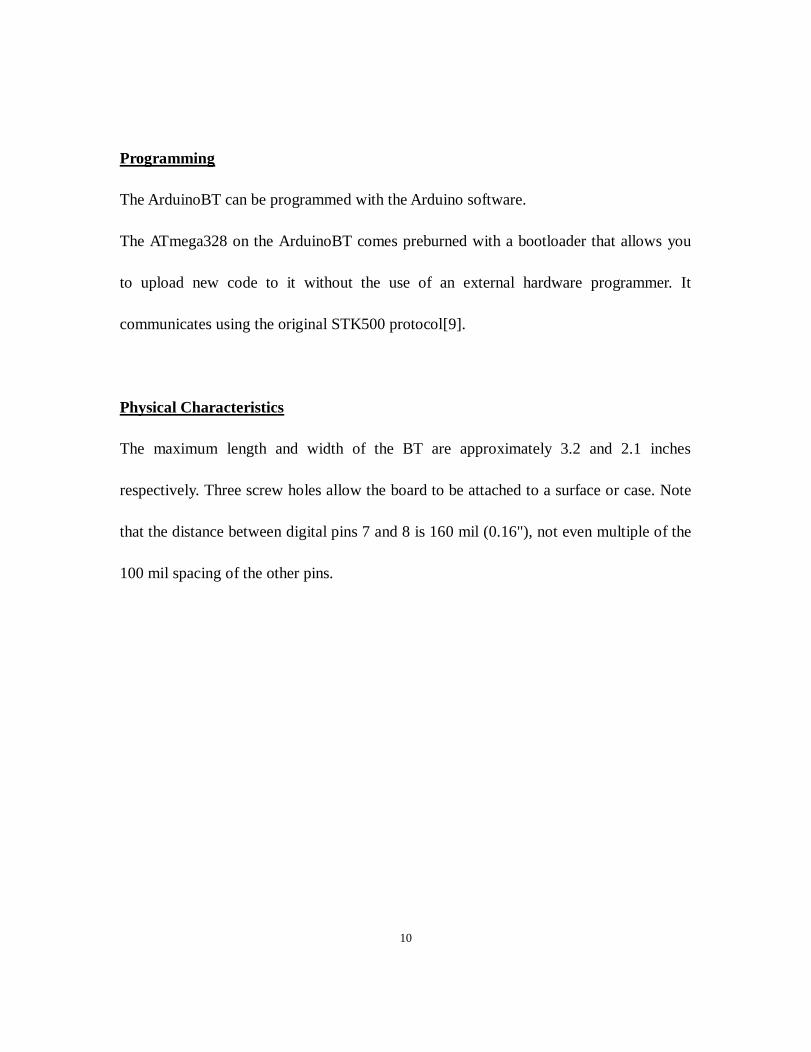
Programming
The ArduinoBT can be programmed with the Arduino software.
The ATmega328 on the ArduinoBT comes preburned with a bootloader that allows you
to upload new code to it without the use of an external hardware programmer. It
communicates using the original STK500 protocol[9].
Physical Characteristics
The maximum length and width of the BT are approximately 3.2 and 2.1 inches
respectively. Three screw holes allow the board to be attached to a surface or case. Note
that the distance between digital pins 7 and 8 is 160 mil (0.16"), not even multiple of the
100 mil spacing of the other pins.
11
Chapter 3
Design of System
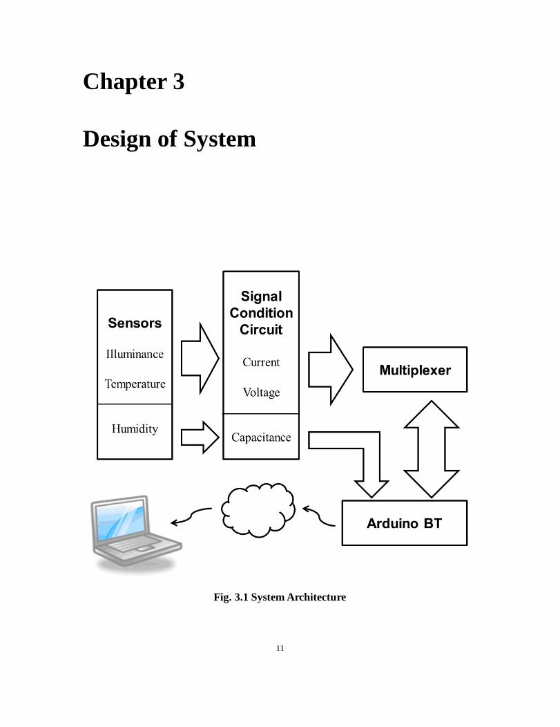
Fig. 3.1 System Architecture

12
The main structure of the system is shown in Fig. 4.3 Sensors detect the signal from the
real physical world, and convert them to signals that can be processed electrically. The
signal conditioning circuit amplifies the useful signals and also converts them to signals
from 0 to 5V which can be accepted by ArduinoBT. Multiplexer works as analog
switches that can control the input of ArduinoBT, which is used to make several sensors
talk to the microcontroller at the same time. Arduino is programmed to convert the
electric analog input value to significant digital output value which is in the real physical
unit and send to the computer.
3.1 Introduction of Sensors
BPW46 Photo Diode
Fig. 3.2 BPW46 Photo Diode

13
BPW46[10] is a PIN photodiode with high speed and high radiant sensitivity in a clear,
side view plastic package. It is sensitive to visible and near infrared radiation. When light
falls on the junction, reverse current flows which is proportional to illuminance as the
figure shown below.
Fig. 3.3 Reverse Light Current vs. Illuminance[10]
ln 𝐼𝑠𝑒𝑛𝑠𝑜𝑟 = ln 𝐸𝐴 − 1
𝐼 =𝐸𝐴
10 (1)

14
1N4148 Small signal Diode
Fig. 3.4 1N4148 Diode
1N4148[11] is a standard small switching diode. In this thesis, the 1N4148 diode is used
as a temperature measuring device, since the forward voltage drop across the diode
depends on the temperature as the figure shown.
V =𝑛𝑘𝑇
𝑞[ln(𝐼) − ln(𝐼𝑠)] (2)

15
Fig. 3.5 Forward Voltage vs Ambient Temperature
(Forward current from 0.01 mA to 20 mA, temperature from -40°C to +65 °C)[11]
Humidity sensor
Fig. 3.6 HCH-1000 series humidity sensor

16
The HCH-1000 series humidity sensor [12] is a capacitive polymer sensor designed for
relative humidity measurement. The sensor converts relative humidity value into
capacitance, which can be measured electronically.
Fig. 3.7 Relative Humidity vs Capacitance[12]

17
3.2 Circuit Design
The whole circuit design of the platform is shown below:
Fig. 3.8 Signal Conditioning Circuit
In this circuit, pin V is voltage sensor input, pin I is current sensor input, pin C is
capacitor sensor, GND is ground and VDD is power supply voltage. P4 and P8 are
connected to pin 4 and pin 8 of ArduinoBT respectively. They are connected to pin B and
pin A of CD4051 as control signal of the multiplexer. P2 is connected to pin 2 of

18
ArduinoBT as the capacitor sensor signal input for microcontroller. CD4051 is a single
8-Channel multiplexer, and LT1014 is a quad precision op amp.
Fig. 3.9 PCB and ArduinoBT
Current Input Conditioning Circuit
This part is used to convert the current sensor signal into a voltage signal that the
microcontroller can process easily. In order to do this, the current value is amplified by a
3.3M ohms resistor, and the output is connected to channel 6 of the multiplexer.
𝑉𝑜𝑢𝑡(𝑖) = 𝐼𝑠𝑒𝑛𝑠𝑜𝑟𝑅14 (1)

19
The circuit is shown below.
Fig. 3.10 Current Input Conditioning Circuit
Voltage Input Conditioning Circuit
This part is used to amplify the small voltage sensor to a suitable range that the
microcontroller can accept. In order to do this, the voltage input from sensor is amplified
by a 3.3M ohms resistor, and the output is connected to channel 5 of the multiplexer. The
circuit is shown above.

20
𝑉𝑜𝑢𝑡(𝑣) = (𝑅10+𝑅11
𝑅10) (
𝑅9
𝑅8+𝑅9) (
𝑅6+𝑅7
𝑅6) 𝑉𝑠𝑒𝑛𝑠𝑜𝑟 −
𝑅11
𝑅10(
𝑅13
𝑅12+𝑅13) 𝑉𝐷𝐷 (2)
The circuit is shown below.
Fig. 3.11 Voltage Input Conditioning Circuit
Capacitor Input Conditioning Circuit
This part is used to measure the value of capacitor value of humidity sensor. The output
of this part is different from the conditioning circuit of current and voltage, which is a
frequency signal. The output P2 is connected to ArduinoBT board directly without any
control signal.

21
Consider in this circuit:
𝑅 = 𝑅1 = 𝑅2 = 𝑅3 (3)
The output of P2 is:
𝑇𝑜𝑢𝑡(𝑐) = 2𝑅4𝐶 ln 2 (4)
The circuit is shown below.
Fig. 3.12 Capacitor Input Conditioning Circuit

22
3.3 Multiplexer
CD4051B is a single 8-Channel multiplexer having three binary control inputs A, B and
C, and an inhibit input. When the select channel is turned on, the respective input and
output will be connected [13]. In this circuit, control inputs A and B are connected to pin
8 and pin 4 of ArduinoBT respectively.
Table 3.1 Truth Table
Digital Input Active
Channel
Sensor
Inhibit C B(P4) A(P8)
0 0 0 0 0 None
0 0 0 1 1 None
0 0 1 0 2 None
0 0 1 1 3 None
0 1 0 0 4 None
0 1 0 1 5 Diode
0 1 1 0 6 Photo Diode
0 1 1 1 7 None
1 X X X None None

23
In this circuit, though ArduinoBT has 6 analog input pins, which are enough to receive
only two analog signals from diode and photo diode at the same time. However, the
multiplexer can expand the number of analog signals that ArduinoBT can process at the
same time. With multiplexer, Up to 8 sensors can work at the same time by using only
one analog input of Arduino.

24
Chapter 4
Experimental Procedure
In this chapter, the experimental method, the instrument used, data collection, and other
details are given.
4.1 Bluetooth Connection
Fig. 4.1 BTD211 bluetooth micro USB adapter [14]
BTD211 is a class 1 bluetooth micro USB adapter from Azio Corporation [14]. It is a
ready to use device that come with software called BlueSoleil to establish the connection.

25
However, the software is not required; in this experiment, the software will even cause
some problem.
The steps to set the connection between ArduinoBT and computer are stated below:
1. Install BT adapter
DO NOT install the software with the adapter, it will keep on scanning the ports and
slow down the reaction of Arduino. Let the Windows native driver work and ignore the
other failed installation service, because only the serial communication is necessary.
2. Find Bluetooth device
Turn on the board, then right click on the Bluetooth icon appear on the taskbar > Add a
device > choose ARDUINOBT and input the default pass code 12345 > pair success
3. Check the automatic port setting
Right click on the Bluetooth icon > Open Settings > COM Ports
4. Set the port number and restart PC
Right click on Computer icon > Manage > Device Manager > Ports (COM & LPT) >
26
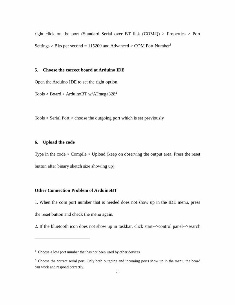
right click on the port (Standard Serial over BT link (COM#)) > Properties > Port
Settings > Bits per second = 115200 and Advanced > COM Port Number1
5. Choose the correct board at Arduino IDE
Open the Arduino IDE to set the right option.
Tools > Board > ArduinoBT w/ATmega3282
Tools > Serial Port > choose the outgoing port which is set previously
6. Upload the code
Type in the code > Compile > Upload (keep on observing the output area. Press the reset
button after binary sketch size showing up)
Other Connection Problem of ArduinoBT
1. When the com port number that is needed does not show up in the IDE menu, press
the reset button and check the menu again.
2. If the bluetooth icon does not show up in taskbar, click start-->control panel-->search
1 Choose a low port number that has not been used by other devices
2 Choose the correct serial port. Only both outgoing and incoming ports show up in the menu, the board
can work and respond correctly.

27
bluetooth
Fig. 4.2 Change Bluetooth settings
Select change bluetooth settings-->show the bluetooth icon in the notification area
Fig. 4.3 Show Bluetooth Icon In the Notification Area

28
4.2 PCB Design
Fig. 4.4 Top Layer of PCB
Fig. 4.5 Bottom Layer of PCB
29
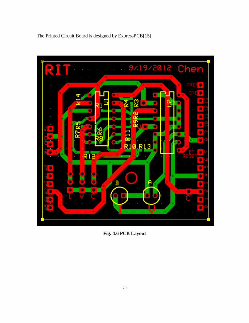
The Printed Circuit Board is designed by ExpressPCB[15].
Fig. 4.6 PCB Layout

30
Table 4.1 PCB Component Values
Component Value Component Value
R1 100 kΩ R8 1 kΩ
R2 100 kΩ R9 2.2 kΩ
R3 100 kΩ R10 1 kΩ
R4 9.1 MΩ R11 2.2 kΩ
R5 20 kΩ R12 1 kΩ
R6 20 kΩ R13 2.2 kΩ
R7 100kΩ R14 3.3 MΩ
4.3 Data Collection and Calculation
Consider that the output values from signal conditioning circuit are still electric signals
that have no significant, so the code burnt in Arduino board has to convert those values
to real physical unit and print out. Once the connection is established, the data from

31
Arduino will be sent to the computer and print out in serial monitor of the IDE
automatically. Those data are collected and organized by Excel.
As stated previously, the outputs of signal conditioning circuit are voltage and frequent.
For Arduino, analogRead (pin) can reads the voltage value from the specified analog pin.
The Arduino board contains a 6-channel 10-bit analog to digital converter. This means
that it will map input voltages between 0 and 5 volts into integer values between 0 and
1023. To measure the frequency signal, the sum of pulseIn(freqPin,LOW) and
pulseIn(freqPin,HIGH) is equal to the period, which is the reciprocal of frequency.
analogRead (V) =𝑉
5∗ 1023 = 204.6𝑉
𝐼𝑠𝑒𝑛𝑠𝑜𝑟 =𝐸𝐴
10
𝑉𝑜𝑢𝑡(𝑖) = 𝐼𝑠𝑒𝑛𝑠𝑜𝑟𝑅14 =𝐸𝐴𝑅14
10
analogRead (A3) = 204.6𝑉𝑜𝑢𝑡(𝑖) = 20.46𝐸𝐴𝑅14
𝐸𝐴 =analogRead (A3)
20.46𝑅14= 𝑎 ∗ analogRead (A3)
a is a positive constant which can be determined by data collected.

32
For diode, since
𝑉𝑜𝑢𝑡(𝑣) = (𝑅10 + 𝑅11
𝑅10
) (𝑅9
𝑅8 + 𝑅9
) (𝑅6 + 𝑅7
𝑅6
) 𝑉𝑠𝑒𝑛𝑠𝑜𝑟 −𝑅11
𝑅10
(𝑅13
𝑅12 + 𝑅13
) 𝑉𝐷𝐷
𝑉𝑜𝑢𝑡(𝑣) ∝ 𝑉𝑠𝑒𝑛𝑠𝑜𝑟 ∝ 𝑇
So the relation between temperature and voltage can be expressed approximately as
𝑇 = 𝑏 ∗ analogRead (A3)
b is a negative constant and c is a positive constant.
For the frequency input,
pulseIn(freqPin, LOW) + pulseIn(freqPin, HIGH) =1
2𝑅𝐶 ln 2∝
1
𝑅𝐻
𝑅𝐻 = 𝑑 ∗ [pulseIn(freqPin,LOW)+ pulseIn(freqPin,HIGH)] + 𝑒
d is a positive constant and e is a negative constant.

33
Chapter 5
Results Analysis
5.1 Noise
Fig. 5.1 Before De-noise
80
85
90
95
100
0 50 100 150 200 250 300 350 400 450 500 550
EA -
Illu
min
ance
(lx)
Time
Illuminance vs Time

34
From the data collected from serial monitor, there’s some noise signal that is out of
meaningful range obviously, which might be caused by contact resistance, capacitor of
the whole system and also random errors. In order to cancel those noise, a de-noise
algorithm can be necessary.
Notice that the noise data are discontinuous and also different much from adjacent data, a
simple way to calculate the average value of a data group as the output works well .
Fig. 5.2 After De-noise
80
85
90
95
100
0 50 100 150 200 250 300 350 400 450 500 550
EA -
Illu
min
ance
(lx)
Time
Illuminance vs Time

35
The accuracy depends on the number of data of one group. The more data one group has,
the result is more accurate. On the other hand, the output rate is slower at the same time.
5.2 Calibration
All the output results are depends on ideal physical models and theoretical calculations,
which might vary measured in different situations. In this thesis, the constant numbers
are determined by the data collected in the experiment. In order to get accurate outputs,
those parameters should be calibrated if apply in different cases.
5.3 Low Power Consumption
When ArduinoBT works under normal mode, the power consumption is not quite low,
since Bluegiga WT11 bluetooth module and BTD211 bluetooth micro USB adapter are
class 1 devices which can make the communication distance as long as 100m (both
indoor and outdoor, also vary by obstacles).

36
Table 5.1 Feature Estimate
Band 2.4GHz
Power >=100mW
Battery Life 3 AA Alkaline batteries work 2 days
Range ~100m
Data Rate 112.5kB/s
Input Voltage 1.2~5.5 V
In some applications, the battery might be inconvenient to replace, like sensors in human
body. Then low power consumption becomes much more significant. Both Bluegiga
WT11 and ATmega328 can work under sleep mode that can save much power
consumption. Different sleep mode can make the system work differently, and there are
also different options to wake up the system.

37
Chapter 6
Conclusions
The results show that the wireless platform stated in this thesis is compatible for most
kind of MEMS sensors, and the accuracy of result is satisfactory. In this experiment, the
signal conditioning circuit is built on PCB; when it is applied on a real application, this
part can be designed as integrated circuit which can be very small and portable[16].
Furthermore, by changing the name of Arduino device several platform can talk to the
host computer at the same time as a wireless star network. By sleep mode, the system
can work only at selected time to save much power.
However, 2.1+ EDR bluetooth technology is not the best choice for every wireless
application. The latest 4.0 bluetooth, which is also known as Bluetooth low energy, can
provide considerably reduced power consumption and low cost, while maintaining a
similar communication range.

38
Reference
[1] Quang-Dung Ho and Tho Le-Ngoc, “An integrated wireless communications
platform for smart electronic healthcare applications”, 24th Canadian Conference on
Electrical and Computer Engineering (CCECE), Niagara Falls, May 2011, pp. 1544 -
1547
[2] D. Khadraoui, and T. Sukuvaara, "Wireless Traffic Service Communication Platform
for Cars", in Ubiroads 2009 - 2st IEEE International Workshop on ITS for an Ubiquitous
ROADS co-located with IEEE GIIS 2009, Hammamet, Tunisia, June 2009, pp. 1-7.
[3] Arduino - ArduinoBoardBT. [Online].
http://arduino.cc/en/Main/ArduinoBoardBT?from=Main.ArduinoBoardBluetooth
[4] Atmel, “Atmel 8-bit Microcontroller with 4/8/16/32KBytes In-System Programmable
Flash”, 8271ES–AVR datasheet, JUL. 2012
[5] Bluegiga Technologies, “WT11 Bluetooth® Module description”, Oct. 2009.
[6] Arduino - EEPROM. [Online]. http://www.arduino.cc/en/Reference/EEPROM
[7] Arduino - Reference. [Online]. http://arduino.cc/en/Reference/HomePage
[8] Arduino - ArduinoBT Initialization Sketch. [Online].
http://arduino.cc/en/Main/ArduinoBTInitializationSketch
[9] Atmel, “AVR061: STK500 Communication Protocol”, 2525B–AVR datasheet, Apr.
2003.
[10] Vishay, “Silicon PIN Photodiode”, 81524datasheet, Nov. 2011.
[11] Fairchild Semiconductor, “1N/FDLL 914/A/B / 916/A/B / 4148 / 4448
Small Signal Diode”, Jan. 2007.

39
[12] Honeywell, “HCH-1000 Series Capacitive Humidity Sensor”, 009019-1-EN
datasheet, Jul. 2007.
[13] Texas Instruments, “CMOS Analog Multiplexers/Demultiplexers with Logic Level
Conversion”, SCHS047G datasheet, October 2003
[14] Azio, “Bluetooth Micro USB Adapter, Model: BTD211”.
[15] ExpressPCB. [Online]. http://www.expresspcb.com/
[16] Bogdan A. G, Joshua K. H, et “A 0.18um CMOS Bluetooth Frequency Synthesizer
for Integration with a Bluetooth SOC Reference Platform”, in IEEE Int. System-on-Chip,
2003.

40
Appendix A
Main Code
/*
Measure three sensors at the same time
***Use average value as output to cancel noise.
*/
//temperature sensor
void setup()
Serial.begin(115200);
pinMode(4,OUTPUT); //B
pinMode(8,OUTPUT); //A
//analogReference(INTERNAL); // Internal regulated 1.1V

41
//cancel diode noise
int temp[30];
int sum=0;
//varieties for humidity
int freqPin = 2; //Input pin 2 for frequency
int period = 0; //Initilize period measuremtn to zero
float cap = 0; //[pF]
float res = 10.3; //[Mohm]
int period_positive=0;
void loop()
//Diode
digitalWrite(4,LOW); //Set B=0
digitalWrite(8,HIGH); //Set A=1
sum = 0;
for (int i=0;i<30;i++)
//cancel noise

42
temp[i]=analogRead(A3);
sum = sum+temp[i];
int temp = -(sum/30-362.5)/4.1;
//Serial.print(sum/30, DEC);
delay(1000);
//Light
digitalWrite(4,HIGH); //Set B=1
digitalWrite(8,LOW); //Set A=0
float light = analogRead(A3);
light = light*100/1011;
delay(1000);
//Humidity
period = pulseIn(freqPin,LOW) + pulseIn(freqPin,HIGH);
//Reads time [us] for high square wave to go LOW
//Serial.print("Period = ");
//Serial.print(period);

43
//Serial.println(" us");
cap = period/2/log(2)/(res)-14; //T=2*ln2*R*C
//Serial.print("Capicator is: ");
//Serial.print(cap);
//Serial.println( "pF");
int rh = (cap-317)/0.6;
//print out data
Serial.print("Temperature is: ");
Serial.print(temp, DEC);
Serial.print(" ");
Serial.print("Light is: ");
Serial.print(light, DEC);
Serial.print("% ");
Serial.print("Relative humidity is: ");
Serial.print(rh);
Serial.println( "%");
delay(1000);

44
Appendix B
Changing Name of Arduino Code
int LED = 13; // select the pin for the LED
int RESET = 7; // BT module uses pin 7 for reset
void setup()
pinMode(LED,OUTPUT); // declare the LED and BT RESET pins as
output
pinMode(RESET,OUTPUT);
Serial.begin(115200); // set the BT module serial rate to 115200
digitalWrite(RESET, HIGH);
delay(10);
digitalWrite(RESET, LOW);
delay(2000);
/* the following "SET BT" commands are one-time commands that can be uploaded
when the name or * password has to be changed
*/

45
Serial.println("SET BT NAME ChenArduino");
//for example,set name as ”ChenArduino”
// No spaces allowed in the name; names can be up to 256 charccters.
Serial.println("SET BT AUTH * 123123");
//for example, set password as 123123
// the Bluetooth password can be 0 to 16 digit
/*Following code is used to indicate that the code of changing name and password has
been executed */
void loop()
digitalWrite(LED, HIGH);
delay(100);
digitalWrite(LED, LOW);
Serial.println("goodjob!");
delay(1000);
// when the IDE print out “goodjob” and the LED blinks, it means the code works well.

46
Appendix C
Sleep and External Wake Up Code
/*
*External interrupts test
*Wake up the arduinoBT by a low level interrupt
*10/27/12
*
*/
#include <avr/sleep.h>
int wakePin = 2; // pin used for waking up
int sleepStatus = 0; // variable to store a request for sleep
int count = 0; // counter
void wakeUpNow() // here the interrupt is handled after wakeup

47
void setup()
pinMode(wakePin, INPUT);
Serial.begin(115200);
void sleepNow() // here we put the arduino to sleep
set_sleep_mode(SLEEP_MODE_PWR_DOWN); // sleep mode is set here
sleep_enable(); // enables the sleep bit in the mcucr register
// so sleep is possible. just a safety pin
attachInterrupt(0,wakeUpNow, LOW); // use interrupt 0 (pin 2) and run function
// wakeUpNow when pin 2 gets LOW
// turn off brown-out enable in software
MCUCR = _BV (BODS) | _BV (BODSE); // turn on brown-out enable select

48
MCUCR = _BV (BODS); // this must be done within 4 clock cycles of above
//sleep_cpu (); // sleep within 3 clock cycles of above
sleep_mode(); // here the device is actually put to sleep!!
/* THE PROGRAM CONTINUES FROM HERE AFTER WAKING UP*/
sleep_disable(); // first thing after waking from sleep:
// disable sleep...
detachInterrupt(0); // disables interrupt 0 on pin 2 so the
// wakeUpNow code will not be executed
// during normal running time.
void loop()
// display information about the counter
Serial.print("Awake for ");
Serial.print(count);
Serial.println("sec");
count++;

49
delay(1000); // waits for a second
// check if it should go to sleep because of time
if (count >= 10)
Serial.println("Timer: Entering Sleep mode");
delay(100); // this delay is needed, the sleep
//function will provoke a Serial error otherwise!!
count = 0;
sleepNow(); // sleep function called here

50
Appendix D
WT11 Sleep and Wake Up Code
/*
*WT-11 Sleep Test
*Wake up the arduinoBT by a low level interrupt
*10/27/12
*
*/
#include <EEPROM.h>
int ledPin = 13; // LED connected to digital pin 13
int resetPin = 7; // BT module uses pin 7 for reset
// which is high active
char inByte = 0; // incoming serial byte
int infoSize = 0 ;

51
void setup() // run once, when the sketch starts
pinMode(ledPin, OUTPUT); // sets the digital pin as output
pinMode(resetPin, OUTPUT);
Serial.begin(115200); // start serial at 115200 kbs
Serial.println("SET CONTROL ESCAPE 43 00 0");
Serial.println("SET CONTROL CONFIG 10");
void loop()
// if we get a valid byte, read analog ins:
if (Serial.available() > 0)
inByte = getbyte(); // get incoming byte
if (inByte == '&' ) // look for a &
Serial.print("Got an & ");

52
infoSize = getInfo();
Serial.println("Done");
else if (inByte == '@' ) // look for a 0
digitalWrite(ledPin, LOW); // set led LOW
Serial.print("Get string: ");
for(int i=0;i<infoSize;i++)
Serial.print(EEPROM.read(i));
Serial.println();
Serial.print("Cleared string size: ");
Serial.println(infoSize);

53
int getInfo()
int j=0;
digitalWrite(ledPin, HIGH); // set led HIGH
delay(2000);
Serial.print("+++");
delay(2000);
Serial.println("TEST DEEPSLEEP"); //THIS IS WHERE YOU ENTER THE
COMMANDS
//"INFO" and "TEST DEEPSLEEP" are both
successful
//"SLEEP" isn't successful yet
for (int i=0; i <= 10; i++)
delay(5000);
while(Serial.available() > 0 && j <512)

54
inByte = getbyte(); // get incoming byte
EEPROM.write(j, inByte);
j++;
delay(5000);
delay(2000);
Serial.print("+++");
delay(2000);
digitalWrite(ledPin, LOW); // set led low
pinMode(resetPin, INPUT);
digitalWrite(resetPin,HIGH);
pinMode(resetPin, OUTPUT);
return j;
char getbyte()
while (Serial.available() == 0) //look for aviable data
// do nothing, wait for incoming data

55
return Serial.read(); //return data if aviable

56
Appendix E
ArduinoBT 06


![Modeling MEMS Sensors [SUGAR: A Computer Aided Design Tool for MEMS ]](https://img.pdfslide.net/doc/110x75/56814044550346895dabb563/modeling-mems-sensors-sugar-a-computer-aided-design-tool-for-mems-.jpg)