Embed Size (px)
Citation preview
347
Architecture
chapter
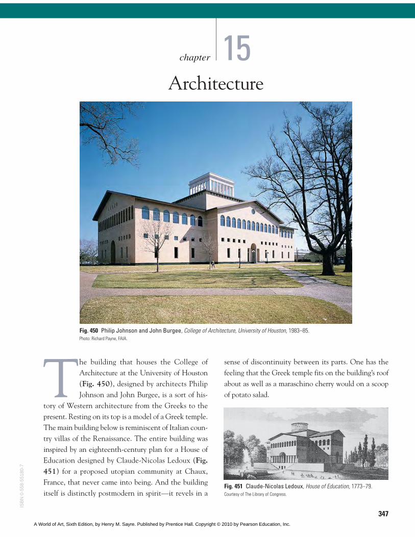
Fig. 450 Philip Johnson and John Burgee, College of Architecture, University of Houston, 1983–85.Photo: Richard Payne, FAIA.
The building that houses the College ofArchitecture at the University of Houston(Fig. 450), designed by architects PhilipJohnson and John Burgee, is a sort of his-
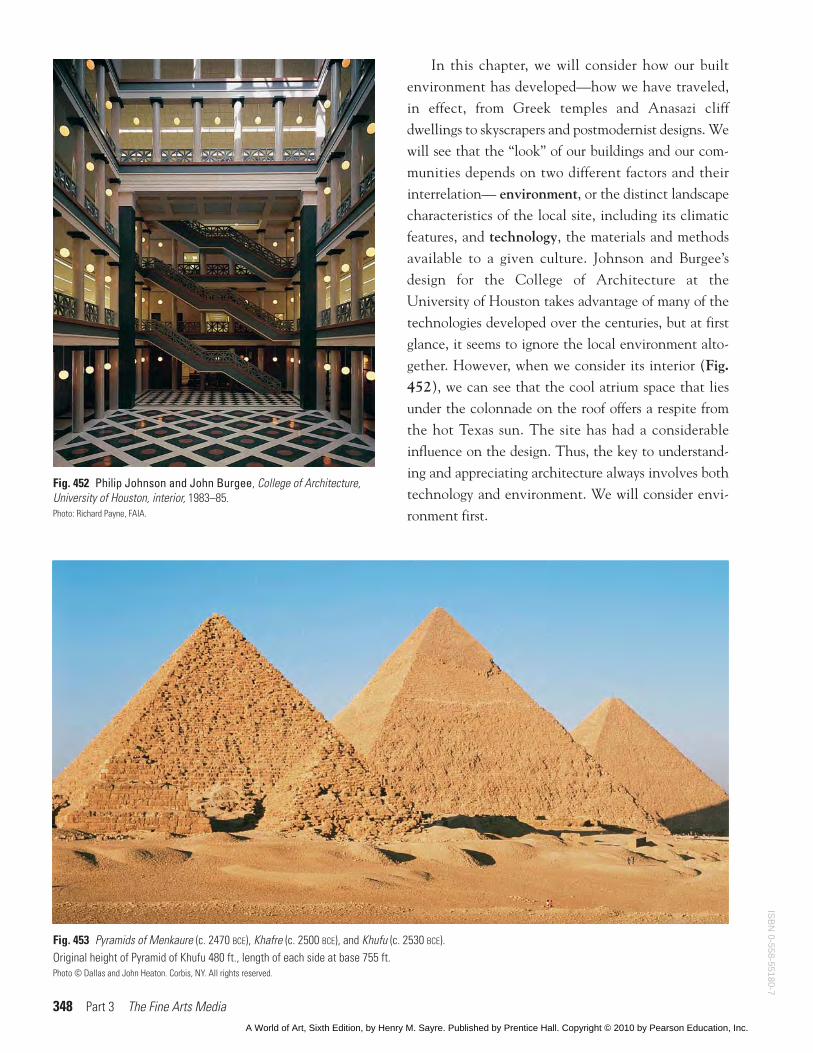
tory of Western architecture from the Greeks to thepresent. Resting on its top is a model of a Greek temple.The main building below is reminiscent of Italian coun-try villas of the Renaissance. The entire building wasinspired by an eighteenth-century plan for a House ofEducation designed by Claude-Nicolas Ledoux (Fig.451) for a proposed utopian community at Chaux,France, that never came into being. And the buildingitself is distinctly postmodern in spirit—it revels in a
sense of discontinuity between its parts. One has thefeeling that the Greek temple fits on the building’s roofabout as well as a maraschino cherry would on a scoopof potato salad.
15
Fig. 451 Claude-Nicolas Ledoux, House of Education, 1773–79.Courtesy of The Library of Congress.
ISB
N 0
-558
-551
80-7
A World of Art, Sixth Edition, by Henry M. Sayre. Published by Prentice Hall. Copyright © 2010 by Pearson Education, Inc.
348 Part 3 The Fine Arts Media
In this chapter, we will consider how our builtenvironment has developed—how we have traveled,in effect, from Greek temples and Anasazi cliffdwellings to skyscrapers and postmodernist designs. Wewill see that the “look” of our buildings and our com-munities depends on two different factors and theirinterrelation— environment, or the distinct landscapecharacteristics of the local site, including its climaticfeatures, and technology, the materials and methodsavailable to a given culture. Johnson and Burgee’sdesign for the College of Architecture at theUniversity of Houston takes advantage of many of thetechnologies developed over the centuries, but at firstglance, it seems to ignore the local environment alto-gether. However, when we consider its interior (Fig.452), we can see that the cool atrium space that liesunder the colonnade on the roof offers a respite fromthe hot Texas sun. The site has had a considerableinfluence on the design. Thus, the key to understand-ing and appreciating architecture always involves bothtechnology and environment. We will consider envi-ronment first.
Fig. 452 Philip Johnson and John Burgee, College of Architecture,University of Houston, interior, 1983–85.Photo: Richard Payne, FAIA.
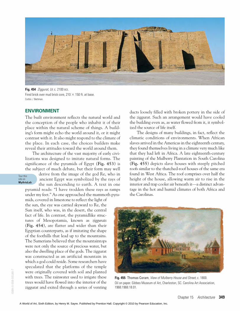
Fig. 453 Pyramids of Menkaure (c. 2470 BCE), Khafre (c. 2500 BCE), and Khufu (c. 2530 BCE).Original height of Pyramid of Khufu 480 ft., length of each side at base 755 ft.Photo © Dallas and John Heaton. Corbis, NY. All rights reserved.
ISB
N 0-558-55180-7
A World of Art, Sixth Edition, by Henry M. Sayre. Published by Prentice Hall. Copyright © 2010 by Pearson Education, Inc.
Chapter 15 Architecture 349
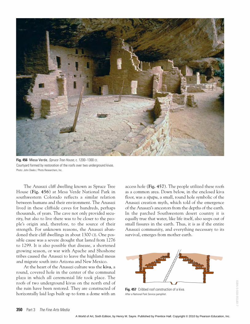
Fig. 454 Ziggurat, Ur, c. 2100 BCE.Fired brick over mud brick core, 210 � 150 ft. at base.Corbis / Bettman.
ENVIRONMENT
The built environment reflects the natural world andthe conception of the people who inhabit it of theirplace within the natural scheme of things. A build-ing’s form might echo the world around it, or it mightcontrast with it. It also might respond to the climate ofthe place. In each case, the choices builders makereveal their attitudes toward the world around them.
The architecture of the vast majority of early civi-lizations was designed to imitate natural forms. Thesignificance of the pyramids of Egypt (Fig. 453) isthe subject of much debate, but their form may well
derive from the image of the god Re, who inancient Egypt was symbolized by the rays ofthe sun descending to earth. A text in one
pyramid reads: “I have trodden these rays as rampsunder my feet.” As one approached the mammoth pyra-mids, covered in limestone to reflect the light ofthe sun, the eye was carried skyward to Re, theSun itself, who was, in the desert, the centralfact of life. In contrast, the pyramidlike struc-tures of Mesopotamia, known as ziggurats(Fig. 454), are flatter and wider than theirEgyptian counterparts, as if imitating the shapeof the foothills that lead up to the mountains.The Sumerians believed that the mountaintopswere not only the source of precious water, butalso the dwelling place of the gods. The zigguratwas constructed as an artificial mountain inwhich a god could reside. Some researchers havespeculated that the platforms of the templewere originally covered with soil and plantedwith trees. The rainwater used to irrigate thesetrees would have flowed into the interior of theziggurat and exited through a series of venting
ducts loosely filled with broken pottery in the side ofthe ziggurat. Such an arrangement would have cooledthe building even as, as water flowed from it, it symbol-ized the source of life itself.
The designs of many buildings, in fact, reflect theclimatic conditions of environments. When Africanslaves arrived in the Americas in the eighteenth century,they found themselves living in a climate very much likethat they had left in Africa. A late eighteenth-centurypainting of the Mulberry Plantation in South Carolina(Fig. 455) depicts slave houses with steeply pitchedroofs similar to the thatched-roof houses of the same erafound in West Africa. The roof comprises over half theheight of the house, allowing warm air to rise in theinterior and trap cooler air beneath it—a distinct advan-tage in the hot and humid climates of both Africa andthe Carolinas.
Fig. 455 Thomas Coram, View of Mulberry House and Street, c. 1800.Oil on paper. Gibbes Museum of Art, Charleston, SC. Carolina Art Association,1968.1968.18.01.
Tour thissite onMyArtsLab
ISB
N 0
-558
-551
80-7
A World of Art, Sixth Edition, by Henry M. Sayre. Published by Prentice Hall. Copyright © 2010 by Pearson Education, Inc.
350 Part 3 The Fine Arts Media
The Anasazi cliff dwelling known as Spruce TreeHouse (Fig. 456) at Mesa Verde National Park insouthwestern Colorado reflects a similar relationbetween humans and their environment. The Anasazilived in these cliffside caves for hundreds, perhapsthousands, of years. The cave not only provided secu-rity, but also to live there was to be closer to the peo-ple’s origin and, therefore, to the source of theirstrength. For unknown reasons, the Anasazi aban-doned their cliff dwellings in about 1300 CE. One pos-sible cause was a severe drought that lasted from 1276to 1299. It is also possible that disease, a shortenedgrowing season, or war with Apache and Shoshonetribes caused the Anasazi to leave the highland mesasand migrate south into Arizona and New Mexico.
At the heart of the Anasazi culture was the kiva, around, covered hole in the center of the communalplaza in which all ceremonial life took place. Theroofs of two underground kivas on the north end ofthe ruin have been restored. They are constructed ofhorizontally laid logs built up to form a dome with an
access hole (Fig. 457). The people utilized these roofsas a common area. Down below, in the enclosed kivafloor, was a sipapu, a small, round hole symbolic of theAnasazi creation myth, which told of the emergenceof the Anasazi’s ancestors from the depths of the earth.In the parched Southwestern desert country it isequally true that water, like life itself, also seeps out ofsmall fissures in the earth. Thus, it is as if the entireAnasazi community, and everything necessary to itssurvival, emerges from mother earth.
Fig. 457 Cribbed roof construction of a kiva.After a National Park Service pamphlet.
Fig. 456 Mesa Verde, Spruce Tree House, c. 1200–1300 CE.Courtyard formed by restoration of the roofs over two underground kivas.Photo: John Deeks / Photo Researchers, Inc.
ISB
N 0-558-55180-7
A World of Art, Sixth Edition, by Henry M. Sayre. Published by Prentice Hall. Copyright © 2010 by Pearson Education, Inc.
Chapter 15 Architecture 351
TECHNOLOGY
The structure of the kiva’s roof represents a techno-logical innovation of the Anasazi culture. Thus,while it responds directly to the environment of theplace, it also reflects the technology available to thebuilder. The basic technological challenge faced byarchitecture is to construct upright walls and put aroof over the empty space they enclose. Walls mayemploy one of two basic structural systems: the shellsystem, in which one basic material provides boththe structural support and the outside covering ofthe building, and the skeleton-and-skin system,which consists of a basic interior frame, the skele-ton, that supports the more fragile outer covering,the skin.
In a building that is several stories tall, the wallsor frame of the lower floors must also support theweight of the upper floors. The ability of a givenbuilding material to support weight is thus a deter-mining factor in how high the building can be. Thewalls or frame also support the roof. The spanbetween the elements of the supporting structure—between, for instance, stone walls, columns, or steelbeams—is determined by the tensile strength of theroof material. Tensile strength is the ability of abuilding material to span horizontal distances with-out support and without buckling in the middle. Thegreater the tensile strength of a material, the widerits potential span. Almost all technologicaladvances in the history of architecture depend oneither the invention of new ways to distributeweight or the discovery of new materi-als with greater tensile strength. Webegin our survey with the most basictechnology and move forward to themost advanced.
Load-Bearing ConstructionThe simplest method of making a build-ing is to make the walls load-bearing—make the walls themselves bear theweight of the roof. One does this by pil-ing and stacking any material—stones,bricks, mud and straw—right up to rooflevel. Many load-bearing structures,such as the pyramids or the ziggurats wehave already seen, are solid almost all
the way through, with only small open chambersinside them. Though the Anasazi cliff dwelling con-tains more livable space than a pyramid or a ziggurat,it too is a load-bearing construction. The kiva is builtof adobe bricks—bricks made of dried clay—piled ontop of one another, and the roof is built of wood. Thecomplex roof of the kiva spans a greater circumferencethan would be possible with just wood, and it supportsthe weight of the community in the plaza above. Thisis achieved by the downward pressure exerted on thewooden beams by the stones and fill on top of themabove the outside wall, which counters the tendencyof the roof to buckle.
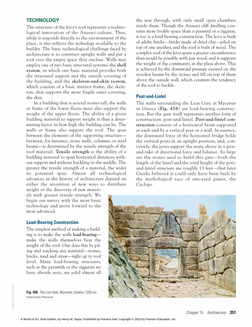
Post-and-LintelThe walls surrounding the Lion Gate at Mycenaein Greece (Fig. 458) are load-bearing construc-tion. But the gate itself represents another form ofconstruction: post-and-lintel. Post-and-lintel con-struction consists of a horizontal beam supportedat each end by a vertical post or a wall. In essence,the downward force of the horizontal bridge holdsthe vertical posts in an upright position, and, con-versely, the posts support the stone above in a give-and-take of directional force and balance. So largeare the stones used to build this gate—both thelength of the lintel and the total height of the post-and-lintel structure are roughly 13 feet—that laterGreeks believed it could only have been built bythe mythological race of one-eyed giants, theCyclops.
Fig. 458 The Lion Gate, Mycenae, Greece, 1250 BCE.Studio Kontos Photostock.
ISB
N 0
-558
-551
80-7
A World of Art, Sixth Edition, by Henry M. Sayre. Published by Prentice Hall. Copyright © 2010 by Pearson Education, Inc.
352 Part 3 The Fine Arts Media
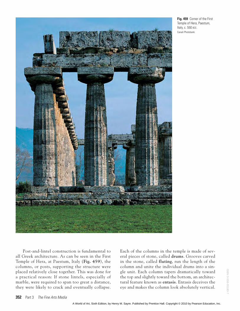
Post-and-lintel construction is fundamental toall Greek architecture. As can be seen in the FirstTemple of Hera, at Paestum, Italy (Fig. 459), thecolumns, or posts, supporting the structure wereplaced relatively close together. This was done fora practical reason: If stone lintels, especially ofmarble, were required to span too great a distance,they were likely to crack and eventually collapse.
Each of the columns in the temple is made of sev-eral pieces of stone, called drums. Grooves carvedin the stone, called fluting, run the length of thecolumn and unite the individual drums into a sin-gle unit. Each column tapers dramatically towardthe top and slightly toward the bottom, an architec-tural feature known as entasis. Entasis deceives theeye and makes the column look absolutely vertical.
Fig. 459 Corner of the FirstTemple of Hera, Paestum,Italy, c. 550 BCE.Canali Photobank.
ISB
N 0-558-55180-7
A World of Art, Sixth Edition, by Henry M. Sayre. Published by Prentice Hall. Copyright © 2010 by Pearson Education, Inc.
Chapter 15 Architecture 353
It also gives the column a sense of almost humanmusculature and strength. The columns suggestthe bodies of human beings, holding up the rooflike miniature versions of the giant Atlas, who car-ried the world on his shoulders.
The values of the Greek city-state were embodiedin its temples. The temple was usually situated on anelevated site above the city—an acropolis, from akros,meaning “top,” of the polis, “city”—and was conceivedas the center of civic life. Its colonnade, or row ofcolumns set at regular intervals around the buildingand supporting the base of the roof, was constructedaccording to the rules of geometry and embodied cul-tural values of equality and proportion. So consistentwere the Greeks in developing a generalized architec-tural type for their temples that it is possible to speakof them in terms of three distinct architectural types—the Doric, the Ionic, and the Corinthian, the last of
which was rarely used by the Greeks themselvesbut later became the standard order in Romanarchitecture (Fig. 460). In ancient times, the
heavier Doric order was considered masculine, and themore graceful Ionic order feminine. It is true that theIonic order is slimmer and much lighter in feelingthan the Doric.
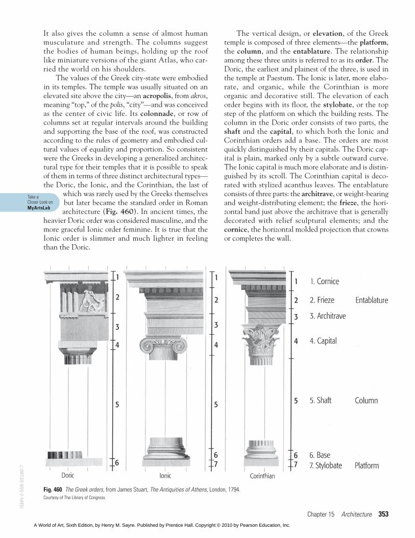
The vertical design, or elevation, of the Greektemple is composed of three elements—the platform,the column, and the entablature. The relationshipamong these three units is referred to as its order. TheDoric, the earliest and plainest of the three, is used inthe temple at Paestum. The Ionic is later, more elabo-rate, and organic, while the Corinthian is moreorganic and decorative still. The elevation of eachorder begins with its floor, the stylobate, or the topstep of the platform on which the building rests. Thecolumn in the Doric order consists of two parts, theshaft and the capital, to which both the Ionic andCorinthian orders add a base. The orders are mostquickly distinguished by their capitals. The Doric cap-ital is plain, marked only by a subtle outward curve.The Ionic capital is much more elaborate and is distin-guished by its scroll. The Corinthian capital is deco-rated with stylized acanthus leaves. The entablatureconsists of three parts: the architrave, or weight-bearingand weight-distributing element; the frieze, the hori-zontal band just above the architrave that is generallydecorated with relief sculptural elements; and thecornice, the horizontal molded projection that crownsor completes the wall.
Fig. 460 The Greek orders, from James Stuart, The Antiquities of Athens, London, 1794.Courtesy of The Library of Congress.
Take a Closer Look onMyArtsLab
ISB
N 0
-558
-551
80-7
A World of Art, Sixth Edition, by Henry M. Sayre. Published by Prentice Hall. Copyright © 2010 by Pearson Education, Inc.
354 Part 3 The Fine Arts Media
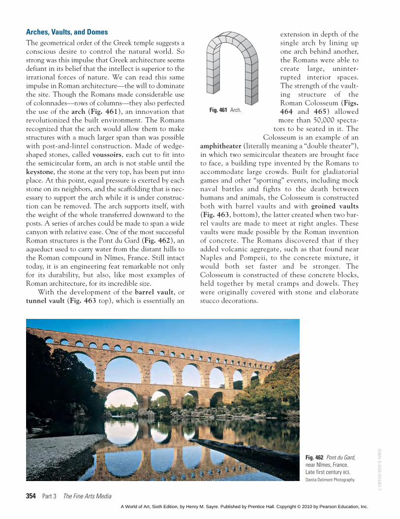
Arches, Vaults, and DomesThe geometrical order of the Greek temple suggests aconscious desire to control the natural world. Sostrong was this impulse that Greek architecture seemsdefiant in its belief that the intellect is superior to theirrational forces of nature. We can read this sameimpulse in Roman architecture—the will to dominatethe site. Though the Romans made considerable useof colonnades—rows of columns—they also perfectedthe use of the arch (Fig. 461), an innovation thatrevolutionized the built environment. The Romansrecognized that the arch would allow them to makestructures with a much larger span than was possiblewith post-and-lintel construction. Made of wedge-shaped stones, called voussoirs, each cut to fit intothe semicircular form, an arch is not stable until thekeystone, the stone at the very top, has been put intoplace. At this point, equal pressure is exerted by eachstone on its neighbors, and the scaffolding that is nec-essary to support the arch while it is under construc-tion can be removed. The arch supports itself, withthe weight of the whole transferred downward to theposts. A series of arches could be made to span a widecanyon with relative ease. One of the most successfulRoman structures is the Pont du Gard (Fig. 462), anaqueduct used to carry water from the distant hills tothe Roman compound in Nîmes, France. Still intacttoday, it is an engineering feat remarkable not onlyfor its durability, but also, like most examples ofRoman architecture, for its incredible size.
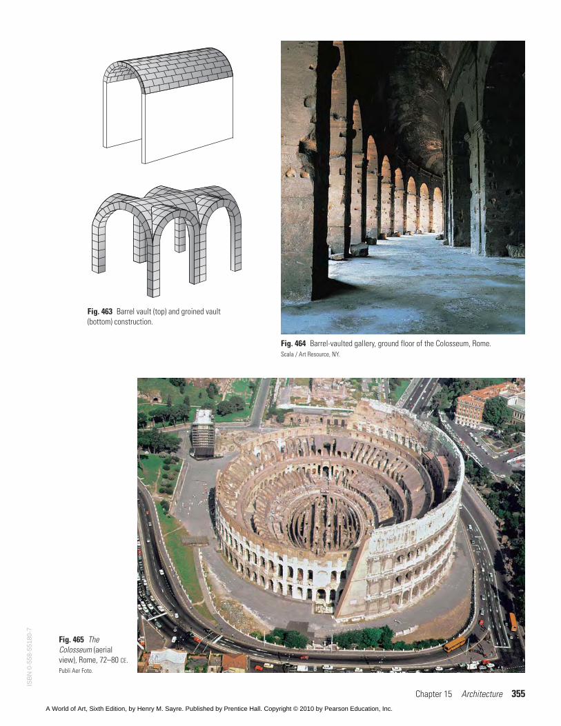
With the development of the barrel vault, ortunnel vault (Fig. 463 top), which is essentially an
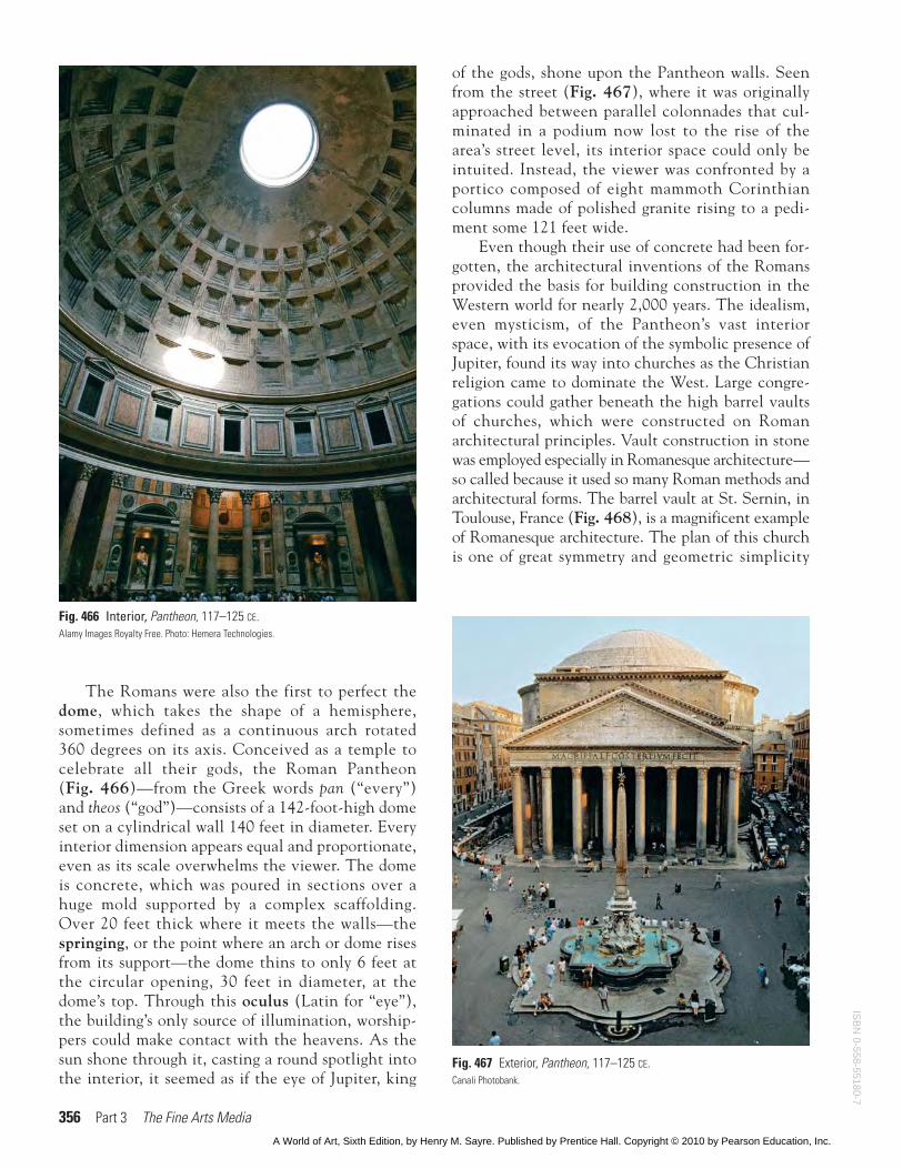
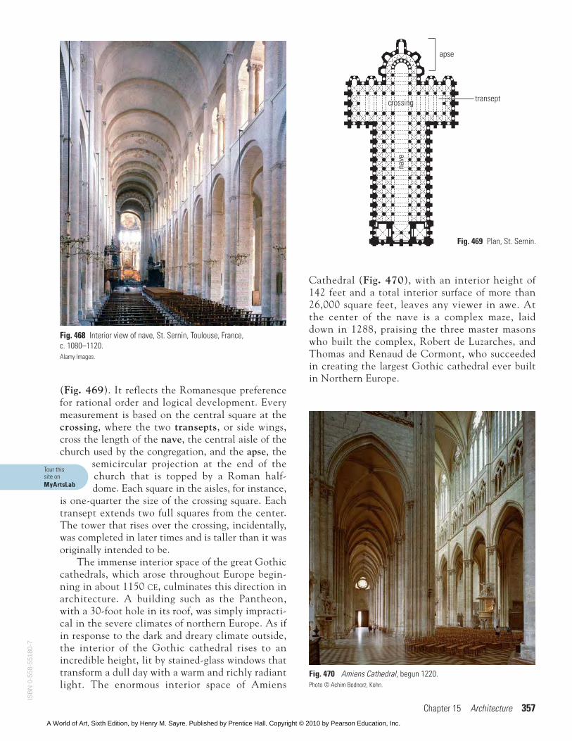
extension in depth of thesingle arch by lining upone arch behind another,the Romans were able tocreate large, uninter-rupted interior spaces.The strength of the vault-ing structure of theRoman Colosseum (Figs.464 and 465) allowedmore than 50,000 specta-
tors to be seated in it. TheColosseum is an example of an
amphitheater (literally meaning a “double theater”),in which two semicircular theaters are brought faceto face, a building type invented by the Romans toaccommodate large crowds. Built for gladiatorialgames and other “sporting” events, including mocknaval battles and fights to the death betweenhumans and animals, the Colosseum is constructedboth with barrel vaults and with groined vaults(Fig. 463, bottom), the latter created when two bar-rel vaults are made to meet at right angles. Thesevaults were made possible by the Roman inventionof concrete. The Romans discovered that if theyadded volcanic aggregate, such as that found nearNaples and Pompeii, to the concrete mixture, itwould both set faster and be stronger. TheColosseum is constructed of these concrete blocks,held together by metal cramps and dowels. Theywere originally covered with stone and elaboratestucco decorations.
Fig. 462 Pont du Gard,near Nîmes, France.Late first century BCE.Danita Delimont Photography.
Fig. 461 Arch.
ISB
N 0-558-55180-7
A World of Art, Sixth Edition, by Henry M. Sayre. Published by Prentice Hall. Copyright © 2010 by Pearson Education, Inc.
Chapter 15 Architecture 355
Fig. 465 TheColosseum (aerialview), Rome, 72–80 CE.Publi Aer Foto.
Fig. 464 Barrel-vaulted gallery, ground floor of the Colosseum, Rome.Scala / Art Resource, NY.
Fig. 463 Barrel vault (top) and groined vault(bottom) construction.
ISB
N 0
-558
-551
80-7
A World of Art, Sixth Edition, by Henry M. Sayre. Published by Prentice Hall. Copyright © 2010 by Pearson Education, Inc.
356 Part 3 The Fine Arts Media
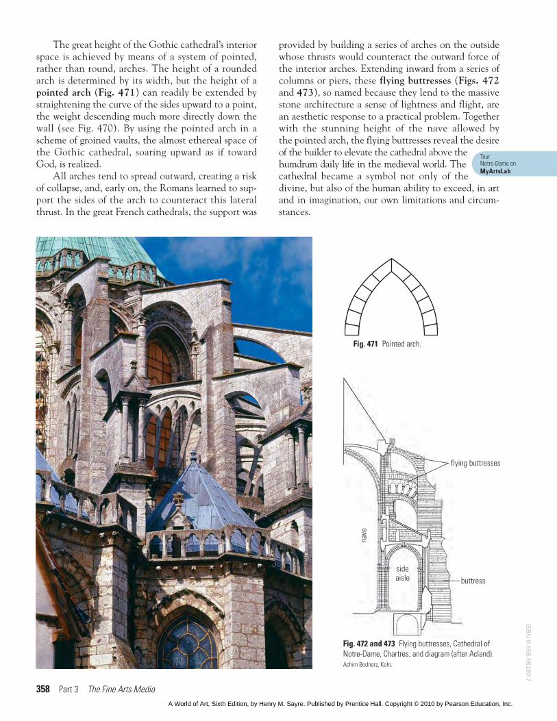
The Romans were also the first to perfect thedome, which takes the shape of a hemisphere,sometimes defined as a continuous arch rotated360 degrees on its axis. Conceived as a temple tocelebrate all their gods, the Roman Pantheon(Fig. 466)—from the Greek words pan (“every”)and theos (“god”)—consists of a 142-foot-high domeset on a cylindrical wall 140 feet in diameter. Everyinterior dimension appears equal and proportionate,even as its scale overwhelms the viewer. The domeis concrete, which was poured in sections over ahuge mold supported by a complex scaffolding.Over 20 feet thick where it meets the walls—thespringing, or the point where an arch or dome risesfrom its support—the dome thins to only 6 feet atthe circular opening, 30 feet in diameter, at thedome’s top. Through this oculus (Latin for “eye”),the building’s only source of illumination, worship-pers could make contact with the heavens. As thesun shone through it, casting a round spotlight intothe interior, it seemed as if the eye of Jupiter, king
of the gods, shone upon the Pantheon walls. Seenfrom the street (Fig. 467), where it was originallyapproached between parallel colonnades that cul-minated in a podium now lost to the rise of thearea’s street level, its interior space could only beintuited. Instead, the viewer was confronted by aportico composed of eight mammoth Corinthiancolumns made of polished granite rising to a pedi-ment some 121 feet wide.
Even though their use of concrete had been for-gotten, the architectural inventions of the Romansprovided the basis for building construction in theWestern world for nearly 2,000 years. The idealism,even mysticism, of the Pantheon’s vast interiorspace, with its evocation of the symbolic presence ofJupiter, found its way into churches as the Christianreligion came to dominate the West. Large congre-gations could gather beneath the high barrel vaultsof churches, which were constructed on Romanarchitectural principles. Vault construction in stonewas employed especially in Romanesque architecture—so called because it used so many Roman methods andarchitectural forms. The barrel vault at St. Sernin, inToulouse, France (Fig. 468), is a magnificent exampleof Romanesque architecture. The plan of this churchis one of great symmetry and geometric simplicity
Fig. 466 Interior, Pantheon, 117–125 CE.Alamy Images Royalty Free. Photo: Hemera Technologies.
Fig. 467 Exterior, Pantheon, 117–125 CE.Canali Photobank.
ISB
N 0-558-55180-7
A World of Art, Sixth Edition, by Henry M. Sayre. Published by Prentice Hall. Copyright © 2010 by Pearson Education, Inc.
Chapter 15 Architecture 357
(Fig. 469). It reflects the Romanesque preferencefor rational order and logical development. Everymeasurement is based on the central square at thecrossing, where the two transepts, or side wings,cross the length of the nave, the central aisle of thechurch used by the congregation, and the apse, the
semicircular projection at the end of thechurch that is topped by a Roman half-dome. Each square in the aisles, for instance,
is one-quarter the size of the crossing square. Eachtransept extends two full squares from the center.The tower that rises over the crossing, incidentally,was completed in later times and is taller than it wasoriginally intended to be.
The immense interior space of the great Gothiccathedrals, which arose throughout Europe begin-ning in about 1150 CE, culminates this direction inarchitecture. A building such as the Pantheon,with a 30-foot hole in its roof, was simply impracti-cal in the severe climates of northern Europe. As ifin response to the dark and dreary climate outside,the interior of the Gothic cathedral rises to anincredible height, lit by stained-glass windows thattransform a dull day with a warm and richly radiantlight. The enormous interior space of Amiens
Cathedral (Fig. 470), with an interior height of142 feet and a total interior surface of more than26,000 square feet, leaves any viewer in awe. Atthe center of the nave is a complex maze, laiddown in 1288, praising the three master masonswho built the complex, Robert de Luzarches, andThomas and Renaud de Cormont, who succeededin creating the largest Gothic cathedral ever builtin Northern Europe.
nave
crossing transept
apse
Fig. 469 Plan, St. Sernin.
Fig. 468 Interior view of nave, St. Sernin, Toulouse, France, c. 1080–1120.Alamy Images.
Fig. 470 Amiens Cathedral, begun 1220.Photo © Achim Bednorz, Kohn.
Tour thissite onMyArtsLab
ISB
N 0
-558
-551
80-7
A World of Art, Sixth Edition, by Henry M. Sayre. Published by Prentice Hall. Copyright © 2010 by Pearson Education, Inc.
358 Part 3 The Fine Arts Media
The great height of the Gothic cathedral’s interiorspace is achieved by means of a system of pointed,rather than round, arches. The height of a roundedarch is determined by its width, but the height of apointed arch (Fig. 471) can readily be extended bystraightening the curve of the sides upward to a point,the weight descending much more directly down thewall (see Fig. 470). By using the pointed arch in ascheme of groined vaults, the almost ethereal space ofthe Gothic cathedral, soaring upward as if towardGod, is realized.
All arches tend to spread outward, creating a riskof collapse, and, early on, the Romans learned to sup-port the sides of the arch to counteract this lateralthrust. In the great French cathedrals, the support was
provided by building a series of arches on the outsidewhose thrusts would counteract the outward force ofthe interior arches. Extending inward from a series ofcolumns or piers, these flying buttresses (Figs. 472and 473), so named because they lend to the massivestone architecture a sense of lightness and flight, arean aesthetic response to a practical problem. Togetherwith the stunning height of the nave allowed bythe pointed arch, the flying buttresses reveal the desireof the builder to elevate the cathedral above thehumdrum daily life in the medieval world. Thecathedral became a symbol not only of thedivine, but also of the human ability to exceed, in artand in imagination, our own limitations and circum-stances.
Fig. 471 Pointed arch.
nave
sideaisle buttress
flying buttresses
Fig. 472 and 473 Flying buttresses, Cathedral ofNotre-Dame, Chartres, and diagram (after Acland).Achim Bodnorz, Koln.
Tour Notre-Dame onMyArtsLab
ISB
N 0-558-55180-7
A World of Art, Sixth Edition, by Henry M. Sayre. Published by Prentice Hall. Copyright © 2010 by Pearson Education, Inc.
Chapter 15 Architecture 359
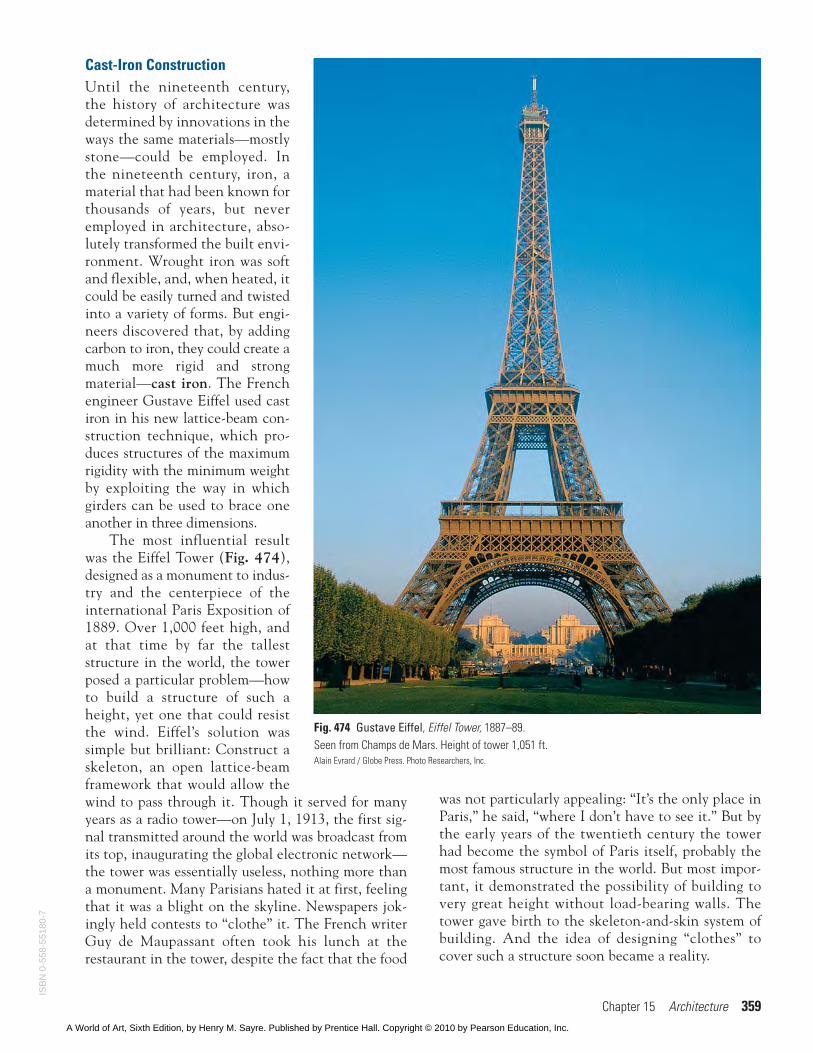
Cast-Iron ConstructionUntil the nineteenth century,the history of architecture wasdetermined by innovations in theways the same materials—mostlystone—could be employed. Inthe nineteenth century, iron, amaterial that had been known forthousands of years, but neveremployed in architecture, abso-lutely transformed the built envi-ronment. Wrought iron was softand flexible, and, when heated, itcould be easily turned and twistedinto a variety of forms. But engi-neers discovered that, by addingcarbon to iron, they could create amuch more rigid and strongmaterial—cast iron. The Frenchengineer Gustave Eiffel used castiron in his new lattice-beam con-struction technique, which pro-duces structures of the maximumrigidity with the minimum weightby exploiting the way in whichgirders can be used to brace oneanother in three dimensions.
The most influential resultwas the Eiffel Tower (Fig. 474),designed as a monument to indus-try and the centerpiece of theinternational Paris Exposition of1889. Over 1,000 feet high, andat that time by far the talleststructure in the world, the towerposed a particular problem—howto build a structure of such aheight, yet one that could resistthe wind. Eiffel’s solution wassimple but brilliant: Construct askeleton, an open lattice-beamframework that would allow thewind to pass through it. Though it served for manyyears as a radio tower—on July 1, 1913, the first sig-nal transmitted around the world was broadcast fromits top, inaugurating the global electronic network—the tower was essentially useless, nothing more thana monument. Many Parisians hated it at first, feelingthat it was a blight on the skyline. Newspapers jok-ingly held contests to “clothe” it. The French writerGuy de Maupassant often took his lunch at therestaurant in the tower, despite the fact that the food
Fig. 474 Gustave Eiffel, Eiffel Tower, 1887–89.Seen from Champs de Mars. Height of tower 1,051 ft.Alain Evrard / Globe Press. Photo Researchers, Inc.
was not particularly appealing: “It’s the only place inParis,” he said, “where I don’t have to see it.” But bythe early years of the twentieth century the towerhad become the symbol of Paris itself, probably themost famous structure in the world. But most impor-tant, it demonstrated the possibility of building tovery great height without load-bearing walls. Thetower gave birth to the skeleton-and-skin system ofbuilding. And the idea of designing “clothes” tocover such a structure soon became a reality.
ISB
N 0
-558
-551
80-7
A World of Art, Sixth Edition, by Henry M. Sayre. Published by Prentice Hall. Copyright © 2010 by Pearson Education, Inc.
360 Part 3 The Fine Arts Media
Frame ConstructionThe role of iron and steel in changing the course ofarchitecture in the nineteenth century cannot beunderestimated—and we will consider steel in evenmore detail in a moment—but two more humble tech-nological innovations had almost as significant animpact, determining the look of our built environ-ment down to the present day. The mass production ofthe common nail, together with improved methodsand standardization in the process of milling lumber,led to a revolution in home building techniques.
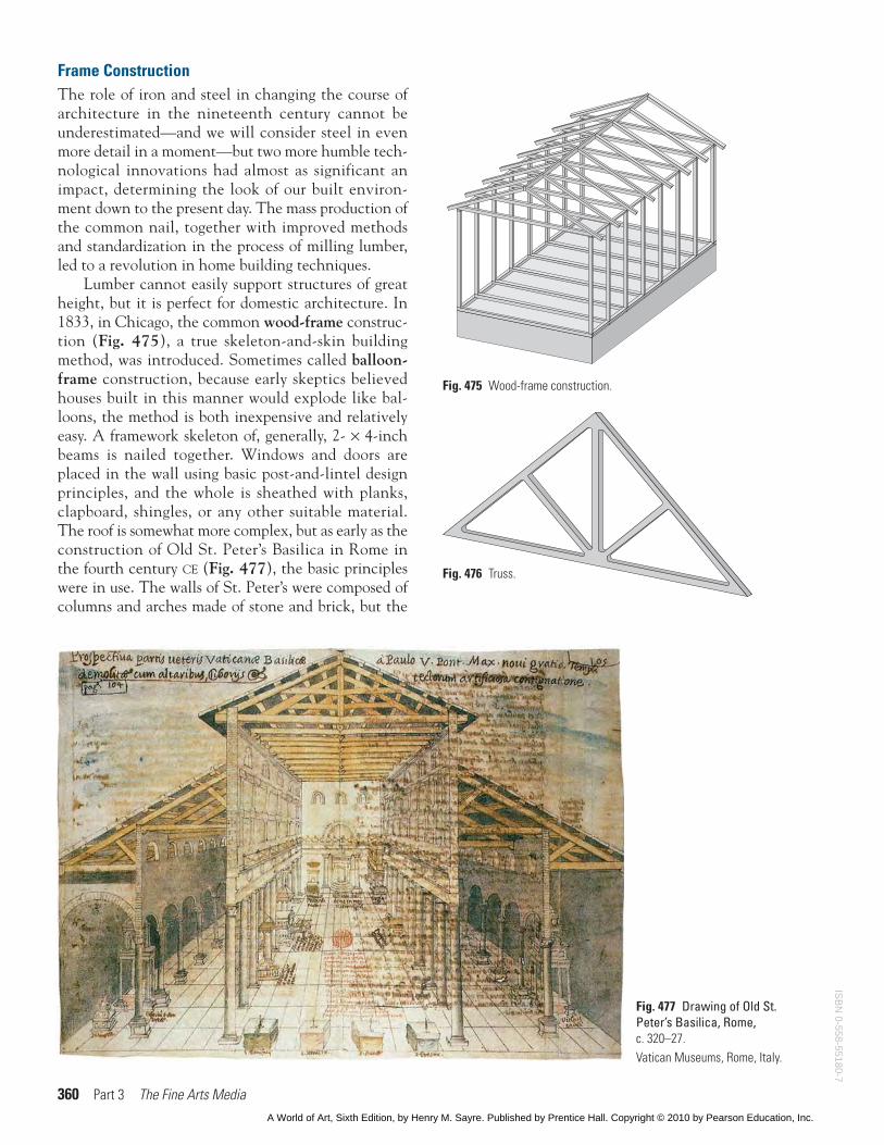
Lumber cannot easily support structures of greatheight, but it is perfect for domestic architecture. In1833, in Chicago, the common wood-frame construc-tion (Fig. 475), a true skeleton-and-skin buildingmethod, was introduced. Sometimes called balloon-frame construction, because early skeptics believedhouses built in this manner would explode like bal-loons, the method is both inexpensive and relativelyeasy. A framework skeleton of, generally, 2- × 4-inchbeams is nailed together. Windows and doors areplaced in the wall using basic post-and-lintel designprinciples, and the whole is sheathed with planks,clapboard, shingles, or any other suitable material.The roof is somewhat more complex, but as early as theconstruction of Old St. Peter’s Basilica in Rome inthe fourth century CE (Fig. 477), the basic principleswere in use. The walls of St. Peter’s were composed ofcolumns and arches made of stone and brick, but the
Fig. 475 Wood-frame construction.
Fig. 477 Drawing of Old St.Peter’s Basilica, Rome,c. 320–27.Vatican Museums, Rome, Italy.
Fig. 476 Truss.
ISB
N 0-558-55180-7
A World of Art, Sixth Edition, by Henry M. Sayre. Published by Prentice Hall. Copyright © 2010 by Pearson Education, Inc.
Chapter 15 Architecture 361
roof was wood. And notice the angled beams support-ing the roof over the aisles. These are elementaryforms of the truss, prefabricated versions of whichmost home builders today use for the roofs of theirhouses. One of the most rigid structural forms in archi-tecture, the truss (Fig. 476) is a triangular frameworkthat, because of its rigidity, can span much wider areasthan a single wooden beam.
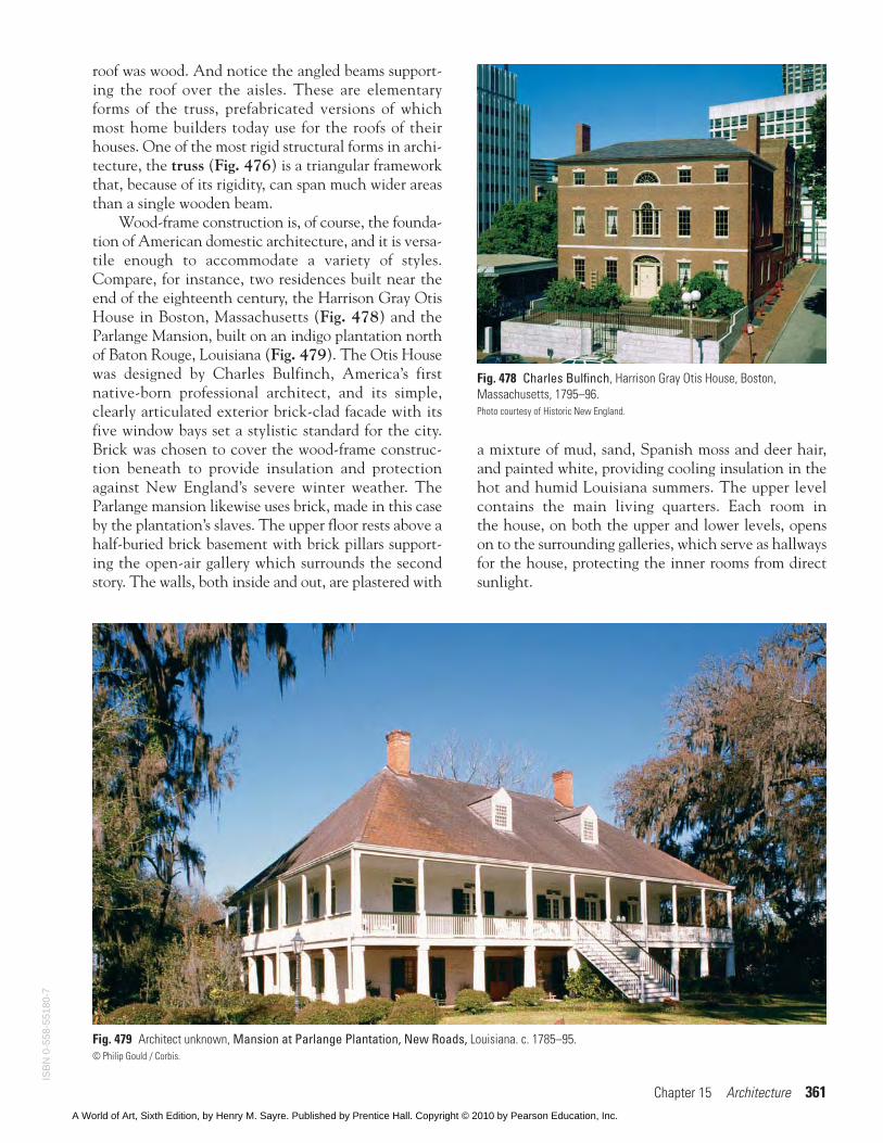
Wood-frame construction is, of course, the founda-tion of American domestic architecture, and it is versa-tile enough to accommodate a variety of styles.Compare, for instance, two residences built near theend of the eighteenth century, the Harrison Gray OtisHouse in Boston, Massachusetts (Fig. 478) and theParlange Mansion, built on an indigo plantation northof Baton Rouge, Louisiana (Fig. 479). The Otis Housewas designed by Charles Bulfinch, America’s firstnative-born professional architect, and its simple,clearly articulated exterior brick-clad facade with itsfive window bays set a stylistic standard for the city.Brick was chosen to cover the wood-frame construc-tion beneath to provide insulation and protectionagainst New England’s severe winter weather. TheParlange mansion likewise uses brick, made in this caseby the plantation’s slaves. The upper floor rests above ahalf-buried brick basement with brick pillars support-ing the open-air gallery which surrounds the secondstory. The walls, both inside and out, are plastered with
a mixture of mud, sand, Spanish moss and deer hair,and painted white, providing cooling insulation in thehot and humid Louisiana summers. The upper levelcontains the main living quarters. Each room inthe house, on both the upper and lower levels, openson to the surrounding galleries, which serve as hallwaysfor the house, protecting the inner rooms from directsunlight.
Fig. 478 Charles Bulfinch, Harrison Gray Otis House, Boston,Massachusetts, 1795–96.Photo courtesy of Historic New England.
Fig. 479 Architect unknown, Mansion at Parlange Plantation, New Roads, Louisiana. c. 1785–95.© Philip Gould / Corbis.
ISB
N 0
-558
-551
80-7
A World of Art, Sixth Edition, by Henry M. Sayre. Published by Prentice Hall. Copyright © 2010 by Pearson Education, Inc.
362 Part 3 The Fine Arts Media
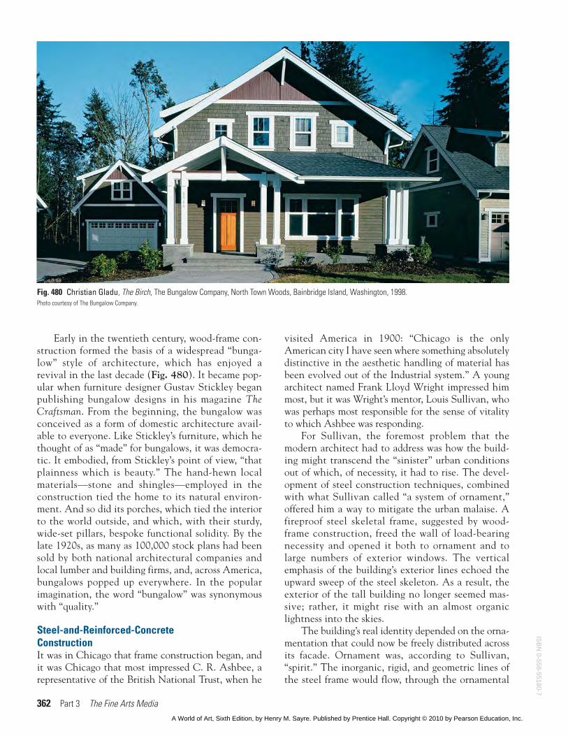
Early in the twentieth century, wood-frame con-struction formed the basis of a widespread “bunga-low” style of architecture, which has enjoyed arevival in the last decade (Fig. 480). It became pop-ular when furniture designer Gustav Stickley beganpublishing bungalow designs in his magazine TheCraftsman. From the beginning, the bungalow wasconceived as a form of domestic architecture avail-able to everyone. Like Stickley’s furniture, which hethought of as “made” for bungalows, it was democra-tic. It embodied, from Stickley’s point of view, “thatplainness which is beauty.” The hand-hewn localmaterials—stone and shingles—employed in theconstruction tied the home to its natural environ-ment. And so did its porches, which tied the interiorto the world outside, and which, with their sturdy,wide-set pillars, bespoke functional solidity. By thelate 1920s, as many as 100,000 stock plans had beensold by both national architectural companies andlocal lumber and building firms, and, across America,bungalows popped up everywhere. In the popularimagination, the word “bungalow” was synonymouswith “quality.”
Steel-and-Reinforced-ConcreteConstructionIt was in Chicago that frame construction began, andit was Chicago that most impressed C. R. Ashbee, arepresentative of the British National Trust, when he
visited America in 1900: “Chicago is the onlyAmerican city I have seen where something absolutelydistinctive in the aesthetic handling of material hasbeen evolved out of the Industrial system.” A youngarchitect named Frank Lloyd Wright impressed himmost, but it was Wright’s mentor, Louis Sullivan, whowas perhaps most responsible for the sense of vitalityto which Ashbee was responding.
For Sullivan, the foremost problem that themodern architect had to address was how the build-ing might transcend the “sinister” urban conditionsout of which, of necessity, it had to rise. The devel-opment of steel construction techniques, combinedwith what Sullivan called “a system of ornament,”offered him a way to mitigate the urban malaise. Afireproof steel skeletal frame, suggested by wood-frame construction, freed the wall of load-bearingnecessity and opened it both to ornament and tolarge numbers of exterior windows. The verticalemphasis of the building’s exterior lines echoed theupward sweep of the steel skeleton. As a result, theexterior of the tall building no longer seemed mas-sive; rather, it might rise with an almost organiclightness into the skies.
The building’s real identity depended on the orna-mentation that could now be freely distributed acrossits facade. Ornament was, according to Sullivan,“spirit.” The inorganic, rigid, and geometric lines ofthe steel frame would flow, through the ornamental
Fig. 480 Christian Gladu, The Birch, The Bungalow Company, North Town Woods, Bainbridge Island, Washington, 1998.Photo courtesy of The Bungalow Company.
ISB
N 0-558-55180-7
A World of Art, Sixth Edition, by Henry M. Sayre. Published by Prentice Hall. Copyright © 2010 by Pearson Education, Inc.
Chapter 15 Architecture 363
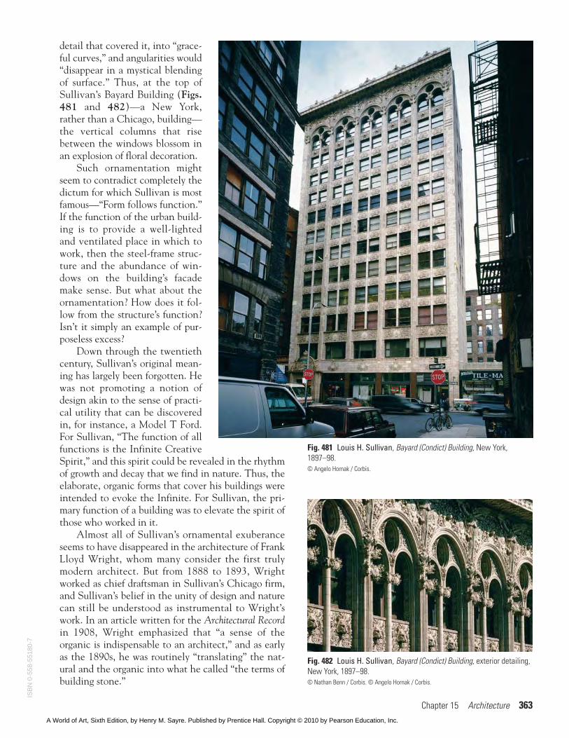
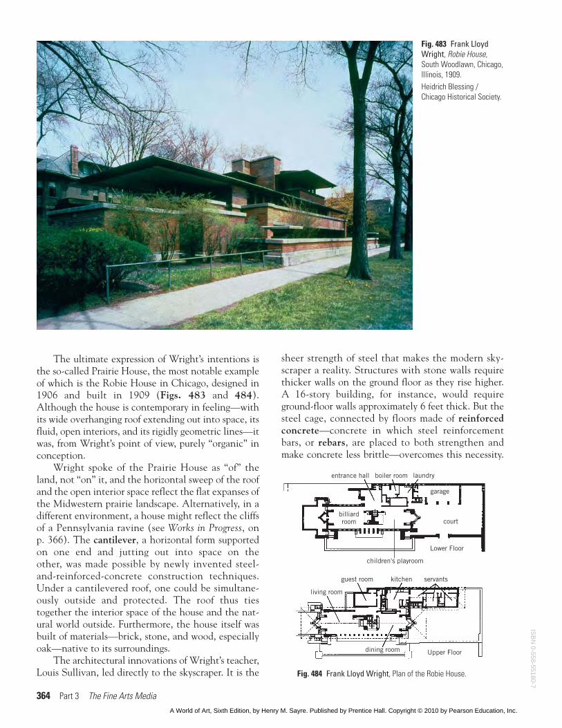
detail that covered it, into “grace-ful curves,” and angularities would“disappear in a mystical blendingof surface.” Thus, at the top ofSullivan’s Bayard Building (Figs.481 and 482)—a New York,rather than a Chicago, building—the vertical columns that risebetween the windows blossom inan explosion of floral decoration.
Such ornamentation mightseem to contradict completely thedictum for which Sullivan is mostfamous—“Form follows function.”If the function of the urban build-ing is to provide a well-lightedand ventilated place in which towork, then the steel-frame struc-ture and the abundance of win-dows on the building’s facademake sense. But what about theornamentation? How does it fol-low from the structure’s function?Isn’t it simply an example of pur-poseless excess?
Down through the twentiethcentury, Sullivan’s original mean-ing has largely been forgotten. Hewas not promoting a notion ofdesign akin to the sense of practi-cal utility that can be discoveredin, for instance, a Model T Ford.For Sullivan, “The function of allfunctions is the Infinite CreativeSpirit,” and this spirit could be revealed in the rhythmof growth and decay that we find in nature. Thus, theelaborate, organic forms that cover his buildings wereintended to evoke the Infinite. For Sullivan, the pri-mary function of a building was to elevate the spirit ofthose who worked in it.
Almost all of Sullivan’s ornamental exuberanceseems to have disappeared in the architecture of FrankLloyd Wright, whom many consider the first trulymodern architect. But from 1888 to 1893, Wrightworked as chief draftsman in Sullivan’s Chicago firm,and Sullivan’s belief in the unity of design and naturecan still be understood as instrumental to Wright’swork. In an article written for the Architectural Recordin 1908, Wright emphasized that “a sense of theorganic is indispensable to an architect,” and as earlyas the 1890s, he was routinely “translating” the nat-ural and the organic into what he called “the terms ofbuilding stone.”
Fig. 481 Louis H. Sullivan, Bayard (Condict) Building, New York,1897–98.© Angelo Hornak / Corbis.
Fig. 482 Louis H. Sullivan, Bayard (Condict) Building, exterior detailing,New York, 1897–98.© Nathan Benn / Corbis. © Angelo Hornak / Corbis.
ISB
N 0
-558
-551
80-7
A World of Art, Sixth Edition, by Henry M. Sayre. Published by Prentice Hall. Copyright © 2010 by Pearson Education, Inc.
364 Part 3 The Fine Arts Media
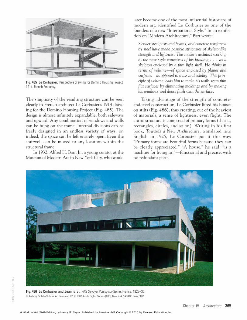
The ultimate expression of Wright’s intentions isthe so-called Prairie House, the most notable exampleof which is the Robie House in Chicago, designed in1906 and built in 1909 (Figs. 483 and 484).Although the house is contemporary in feeling—withits wide overhanging roof extending out into space, itsfluid, open interiors, and its rigidly geometric lines—itwas, from Wright’s point of view, purely “organic” inconception.
Wright spoke of the Prairie House as “of” theland, not “on” it, and the horizontal sweep of the roofand the open interior space reflect the flat expanses ofthe Midwestern prairie landscape. Alternatively, in adifferent environment, a house might reflect the cliffsof a Pennsylvania ravine (see Works in Progress, onp. 366). The cantilever, a horizontal form supportedon one end and jutting out into space on theother, was made possible by newly invented steel-and-reinforced-concrete construction techniques.Under a cantilevered roof, one could be simultane-ously outside and protected. The roof thus tiestogether the interior space of the house and the nat-ural world outside. Furthermore, the house itself wasbuilt of materials—brick, stone, and wood, especiallyoak—native to its surroundings.
The architectural innovations of Wright’s teacher,Louis Sullivan, led directly to the skyscraper. It is the
Fig. 483 Frank LloydWright, Robie House,South Woodlawn, Chicago,Illinois, 1909.Heidrich Blessing /Chicago Historical Society.
entrance hall boiler room laundry
court
Lower Floor
billiardroom
children's playroom
garage
dining room Upper Floor
servantskitchenguest room
living room
Fig. 484 Frank Lloyd Wright, Plan of the Robie House.
sheer strength of steel that makes the modern sky-scraper a reality. Structures with stone walls requirethicker walls on the ground floor as they rise higher.A 16-story building, for instance, would requireground-floor walls approximately 6 feet thick. But thesteel cage, connected by floors made of reinforcedconcrete—concrete in which steel reinforcementbars, or rebars, are placed to both strengthen andmake concrete less brittle—overcomes this necessity.
ISB
N 0-558-55180-7
A World of Art, Sixth Edition, by Henry M. Sayre. Published by Prentice Hall. Copyright © 2010 by Pearson Education, Inc.
Chapter 15 Architecture 365
The simplicity of the resulting structure can be seenclearly in French architect Le Corbusier’s 1914 draw-ing for the Domino Housing Project (Fig. 485). Thedesign is almost infinitely expandable, both sidewaysand upward. Any combination of windows and wallscan be hung on the frame. Internal divisions can befreely designed in an endless variety of ways, or,indeed, the space can be left entirely open. Even thestairwell can be moved to any location within thestructural frame.
In 1932, Alfred H. Barr, Jr., a young curator at theMuseum of Modern Art in New York City, who would
later become one of the most influential historians ofmodern art, identified Le Corbusier as one of thefounders of a new “International Style.” In an exhibi-tion on “Modern Architecture,” Barr wrote:
Slender steel posts and beams, and concrete reinforcedby steel have made possible structures of skeletonlikestrength and lightness. The modern architect workingin the new style conceives of his building . . . as askeleton enclosed by a thin light shell. He thinks interms of volume—of space enclosed by planes andsurfaces—as opposed to mass and solidity. This prin-ciple of volume leads him to make his walls seem thinflat surfaces by eliminating moldings and by makinghis windows and doors flush with the surface.
Taking advantage of the strength of concrete-and-steel construction, Le Corbusier lifted his houseson stilts (Fig. 486), thus creating, out of the heaviestof materials, a sense of lightness, even flight. Theentire structure is composed of primary forms (that is,rectangles, circles, and so on). Writing in his firstbook, Towards a New Architecture, translated intoEnglish in 1925, Le Corbusier put it this way:“Primary forms are beautiful forms because they canbe clearly appreciated.” “A house,” he said, “is amachine for living in!”—functional and precise, withno redundant parts.
Fig. 485 Le Corbusier, Perspective drawing for Domino Housing Project,1914. French Embassy.
Fig. 486 Le Corbusier and Jeanneret, Villa Savoye, Poissy-sur-Seine, France, 1928–30.© Anthony Scibilia Solidus. Art Resource, NY. © 2007 Artists Rights Society (ARS), New York / ADAGP, Paris / FLC.
ISB
N 0
-558
-551
80-7
A World of Art, Sixth Edition, by Henry M. Sayre. Published by Prentice Hall. Copyright © 2010 by Pearson Education, Inc.
366 Part 3 The Fine Arts Media
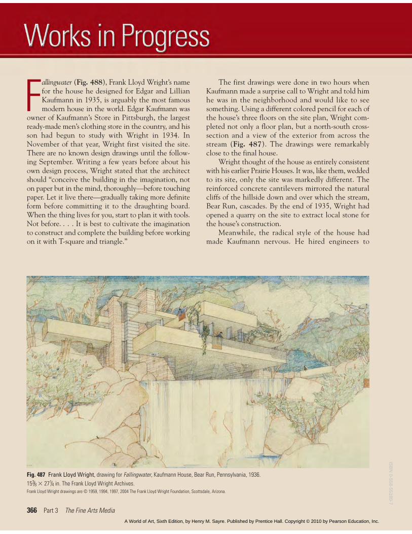
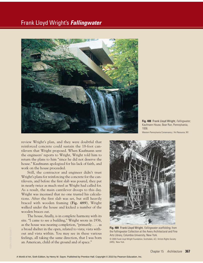
Fallingwater (Fig. 488), Frank Lloyd Wright’s namefor the house he designed for Edgar and LillianKaufmann in 1935, is arguably the most famousmodern house in the world. Edgar Kaufmann was
owner of Kaufmann’s Store in Pittsburgh, the largestready-made men’s clothing store in the country, and hisson had begun to study with Wright in 1934. InNovember of that year, Wright first visited the site.There are no known design drawings until the follow-ing September. Writing a few years before about hisown design process, Wright stated that the architectshould “conceive the building in the imagination, noton paper but in the mind, thoroughly—before touchingpaper. Let it live there—gradually taking more definiteform before committing it to the draughting board.When the thing lives for you, start to plan it with tools.Not before. . . . It is best to cultivate the imaginationto construct and complete the building before workingon it with T-square and triangle.”
The first drawings were done in two hours whenKaufmann made a surprise call to Wright and told himhe was in the neighborhood and would like to seesomething. Using a different colored pencil for each ofthe house’s three floors on the site plan, Wright com-pleted not only a floor plan, but a north-south cross-section and a view of the exterior from across thestream (Fig. 487). The drawings were remarkablyclose to the final house.
Wright thought of the house as entirely consistentwith his earlier Prairie Houses. It was, like them, weddedto its site, only the site was markedly different. Thereinforced concrete cantilevers mirrored the naturalcliffs of the hillside down and over which the stream,Bear Run, cascades. By the end of 1935, Wright hadopened a quarry on the site to extract local stone forthe house’s construction.
Meanwhile, the radical style of the house hadmade Kaufmann nervous. He hired engineers to
Fig. 487 Frank Lloyd Wright, drawing for Fallingwater, Kaufmann House, Bear Run, Pennsylvania, 1936.153/8 � 271/4 in. The Frank Lloyd Wright Archives.Frank Lloyd Wright drawings are © 1959, 1994, 1997, 2004 The Frank Lloyd Wright Foundation, Scottsdale, Arizona.
ISB
N 0-558-55180-7
A World of Art, Sixth Edition, by Henry M. Sayre. Published by Prentice Hall. Copyright © 2010 by Pearson Education, Inc.
review Wright’s plan, and they were doubtful thatreinforced concrete could sustain the 18-foot can-tilevers that Wright proposed. When Kaufmann sentthe engineers’ reports to Wright, Wright told him toreturn the plans to him “since he did not deserve thehouse.” Kaufmann apologized for his lack of faith, andwork on the house proceeded.
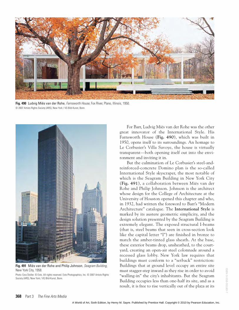
Still, the contractor and engineer didn’t trustWright’s plans for reinforcing the concrete for the can-tilevers, and before the first slab was poured, they putin nearly twice as much steel as Wright had called for.As a result, the main cantilever droops to this day.Wright was incensed that no one trusted his calcula-tions. After the first slab was set, but still heavilybraced with wooden framing (Fig. 489), Wrightwalked under the house and kicked a number of thewooden braces out.
The house, finally, is in complete harmony with itssite. “I came to see a building,” Wright wrote in 1936,as the house was nearing completion, “primarily . . . asa broad shelter in the open, related to vista; vista with-out and vista within. You may see in these variousfeelings, all taking the same direction, that I was bornan American, child of the ground and of space.”
Frank Lloyd Wright’s Fallingwater
Chapter 15 Architecture 367
Fig. 488 Frank Lloyd Wright, Fallingwater,Kaufmann House, Bear Run, Pennsylvania,1936.Western Pennsylvania Conservancy / Art Resource, NY.
Fig. 489 Frank Lloyd Wright, Fallingwater scaffolding, fromthe Fallingwater Collection at the Avery Architectural and FineArts Library, Columbia University, New York.© 2005 Frank Lloyd Wright Foundation, Scottsdale, AZ / Artists Rights Society(ARS), New York.
ISB
N 0
-558
-551
80-7
A World of Art, Sixth Edition, by Henry M. Sayre. Published by Prentice Hall. Copyright © 2010 by Pearson Education, Inc.
368 Part 3 The Fine Arts Media
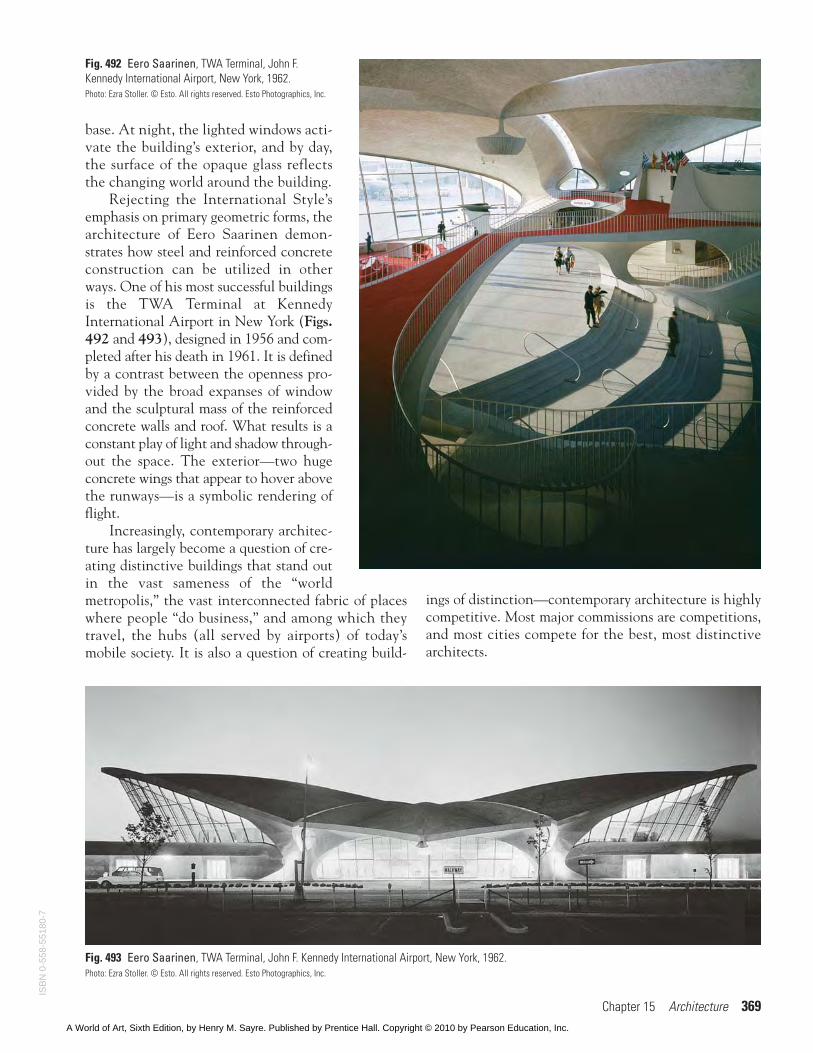
For Barr, Ludvig Miës van der Rohe was the othergreat innovator of the International Style. HisFarnsworth House (Fig. 490), which was built in1950, opens itself to its surroundings. An homage toLe Corbusier’s Villa Savoye, the house is virtuallytransparent—both opening itself out into the envi-ronment and inviting it in.
But the culmination of Le Corbusier’s steel-and-reinforced-concrete Domino plan is the so-calledInternational Style skyscraper, the most notable ofwhich is the Seagram Building in New York City(Fig. 491), a collaboration between Miës van derRohe and Philip Johnson. Johnson is the architectwhose design for the College of Architecture at theUniversity of Houston opened this chapter and who,in 1932, had written the foreword to Barr’s “ModernArchitecture” catalogue. The International Style ismarked by its austere geometric simplicity, and thedesign solution presented by the Seagram Building isextremely elegant. The exposed structural I-beams(that is, steel beams that seen in cross-section looklike the capital letter “I”) are finished in bronze tomatch the amber-tinted glass sheath. At the base,these exterior beams drop, unsheathed, to the court-yard, creating an open-air steel colonnade around arecessed glass lobby. New York law requires thatbuildings must conform to a “setback” restriction:Buildings that at ground level occupy an entire sitemust stagger-step inward as they rise in order to avoid“walling-in” the city’s inhabitants. But the SeagramBuilding occupies less than one-half its site, and as aresult, it is free to rise vertically out of the plaza at its
Fig. 491 Miës van der Rohe and Philip Johnson, Seagram Building,New York City, 1958.Photo: Ezra Stoller. © Esto. All rights reserved. Esto Photographics, Inc. © 2007 Artists RightsSociety (ARS), New York / VG Bild-Kunst, Bonn.
Fig. 490 Ludvig Miës van der Rohe, Farnsworth House, Fox River, Plano, Illinois, 1950.© 2007 Artists Rights Society (ARS), New York / VG Bild-Kunst, Bonn.
ISB
N 0-558-55180-7
A World of Art, Sixth Edition, by Henry M. Sayre. Published by Prentice Hall. Copyright © 2010 by Pearson Education, Inc.
Chapter 15 Architecture 369
base. At night, the lighted windows acti-vate the building’s exterior, and by day,the surface of the opaque glass reflectsthe changing world around the building.
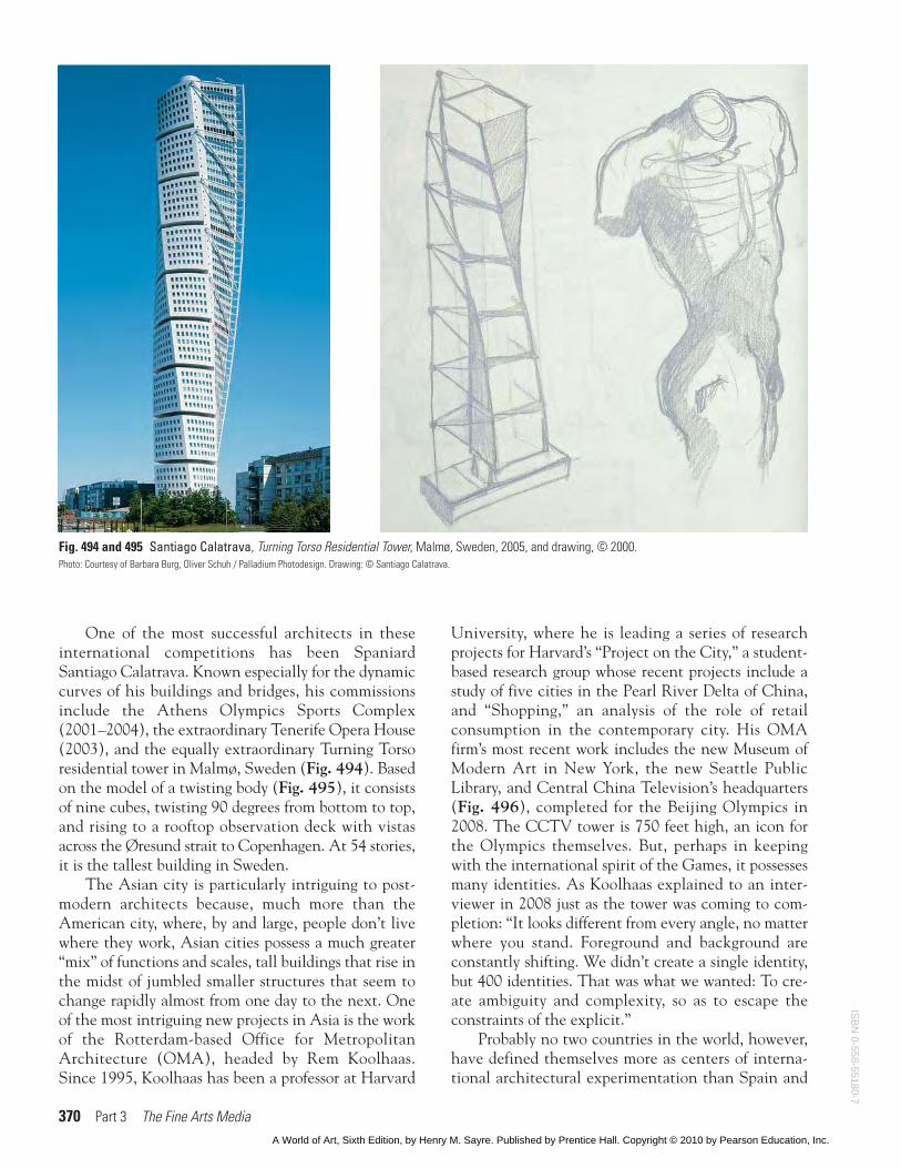
Rejecting the International Style’semphasis on primary geometric forms, thearchitecture of Eero Saarinen demon-strates how steel and reinforced concreteconstruction can be utilized in otherways. One of his most successful buildingsis the TWA Terminal at KennedyInternational Airport in New York (Figs.492 and 493), designed in 1956 and com-pleted after his death in 1961. It is definedby a contrast between the openness pro-vided by the broad expanses of windowand the sculptural mass of the reinforcedconcrete walls and roof. What results is aconstant play of light and shadow through-out the space. The exterior—two hugeconcrete wings that appear to hover abovethe runways—is a symbolic rendering offlight.
Increasingly, contemporary architec-ture has largely become a question of cre-ating distinctive buildings that stand outin the vast sameness of the “worldmetropolis,” the vast interconnected fabric of placeswhere people “do business,” and among which theytravel, the hubs (all served by airports) of today’smobile society. It is also a question of creating build-
Fig. 493 Eero Saarinen, TWA Terminal, John F. Kennedy International Airport, New York, 1962.Photo: Ezra Stoller. © Esto. All rights reserved. Esto Photographics, Inc.
Fig. 492 Eero Saarinen, TWA Terminal, John F.Kennedy International Airport, New York, 1962.Photo: Ezra Stoller. © Esto. All rights reserved. Esto Photographics, Inc.
ings of distinction—contemporary architecture is highlycompetitive. Most major commissions are competitions,and most cities compete for the best, most distinctivearchitects.
ISB
N 0
-558
-551
80-7
A World of Art, Sixth Edition, by Henry M. Sayre. Published by Prentice Hall. Copyright © 2010 by Pearson Education, Inc.
370 Part 3 The Fine Arts Media
One of the most successful architects in theseinternational competitions has been SpaniardSantiago Calatrava. Known especially for the dynamiccurves of his buildings and bridges, his commissionsinclude the Athens Olympics Sports Complex(2001–2004), the extraordinary Tenerife Opera House(2003), and the equally extraordinary Turning Torsoresidential tower in Malmø, Sweden (Fig. 494). Basedon the model of a twisting body (Fig. 495), it consistsof nine cubes, twisting 90 degrees from bottom to top,and rising to a rooftop observation deck with vistasacross the Øresund strait to Copenhagen. At 54 stories,it is the tallest building in Sweden.
The Asian city is particularly intriguing to post-modern architects because, much more than theAmerican city, where, by and large, people don’t livewhere they work, Asian cities possess a much greater“mix” of functions and scales, tall buildings that rise inthe midst of jumbled smaller structures that seem tochange rapidly almost from one day to the next. Oneof the most intriguing new projects in Asia is the workof the Rotterdam-based Office for MetropolitanArchitecture (OMA), headed by Rem Koolhaas.Since 1995, Koolhaas has been a professor at Harvard
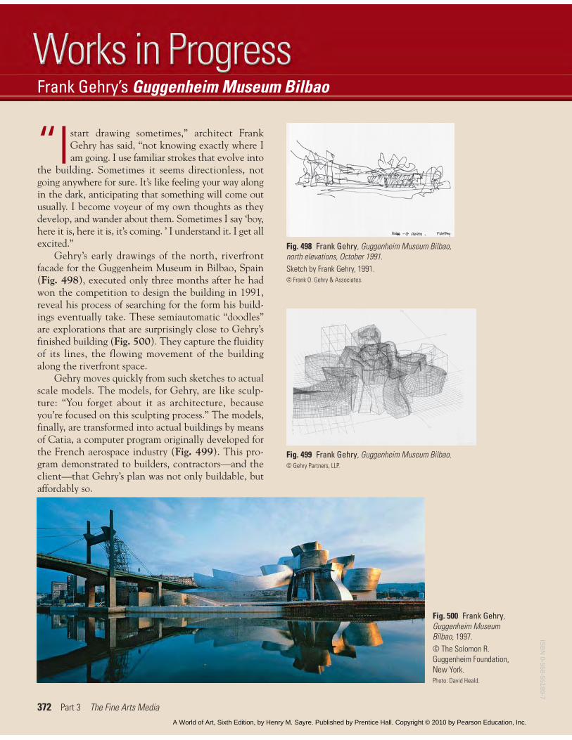
University, where he is leading a series of researchprojects for Harvard’s “Project on the City,” a student-based research group whose recent projects include astudy of five cities in the Pearl River Delta of China,and “Shopping,” an analysis of the role of retailconsumption in the contemporary city. His OMAfirm’s most recent work includes the new Museum ofModern Art in New York, the new Seattle PublicLibrary, and Central China Television’s headquarters(Fig. 496), completed for the Beijing Olympics in2008. The CCTV tower is 750 feet high, an icon forthe Olympics themselves. But, perhaps in keepingwith the international spirit of the Games, it possessesmany identities. As Koolhaas explained to an inter-viewer in 2008 just as the tower was coming to com-pletion: “It looks different from every angle, no matterwhere you stand. Foreground and background areconstantly shifting. We didn’t create a single identity,but 400 identities. That was what we wanted: To cre-ate ambiguity and complexity, so as to escape theconstraints of the explicit.”
Probably no two countries in the world, however,have defined themselves more as centers of interna-tional architectural experimentation than Spain and
Fig. 494 and 495 Santiago Calatrava, Turning Torso Residential Tower, Malmø, Sweden, 2005, and drawing, © 2000.Photo: Courtesy of Barbara Burg, Oliver Schuh / Palladium Photodesign. Drawing: © Santiago Calatrava.
ISB
N 0-558-55180-7
A World of Art, Sixth Edition, by Henry M. Sayre. Published by Prentice Hall. Copyright © 2010 by Pearson Education, Inc.
Chapter 15 Architecture 371
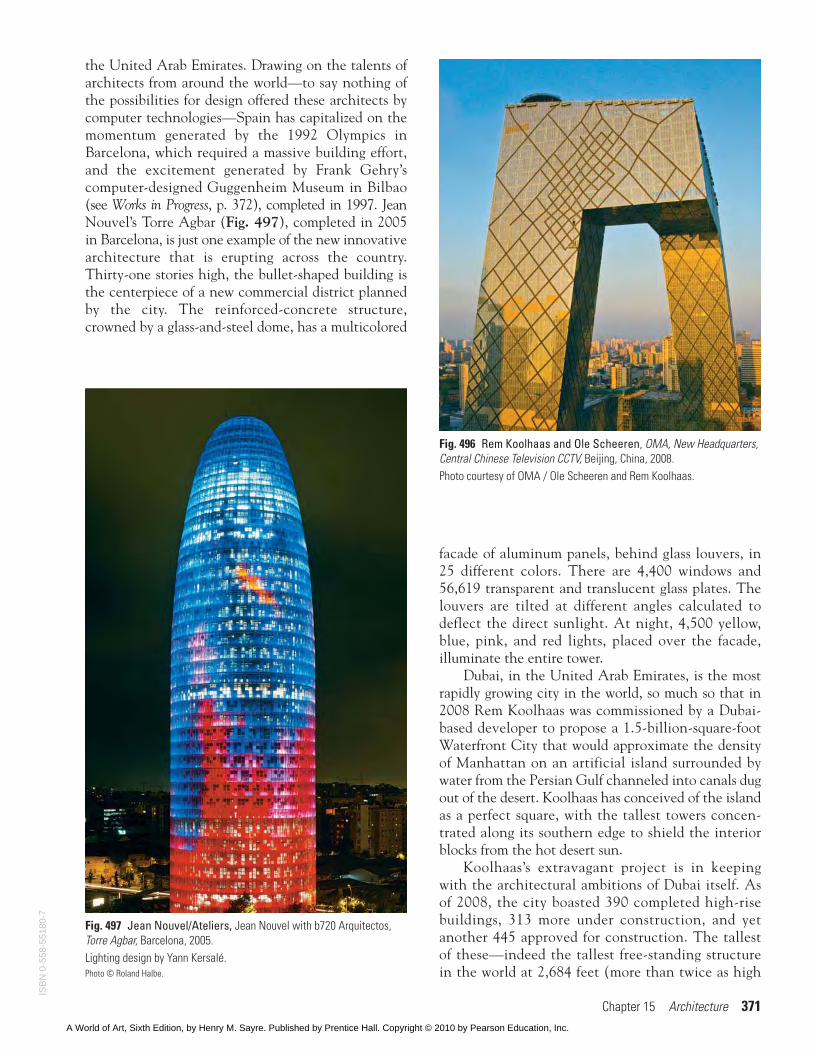
the United Arab Emirates. Drawing on the talents ofarchitects from around the world—to say nothing ofthe possibilities for design offered these architects bycomputer technologies—Spain has capitalized on themomentum generated by the 1992 Olympics inBarcelona, which required a massive building effort,and the excitement generated by Frank Gehry’scomputer-designed Guggenheim Museum in Bilbao(see Works in Progress, p. 372), completed in 1997. JeanNouvel’s Torre Agbar (Fig. 497), completed in 2005in Barcelona, is just one example of the new innovativearchitecture that is erupting across the country.Thirty-one stories high, the bullet-shaped building isthe centerpiece of a new commercial district plannedby the city. The reinforced-concrete structure,crowned by a glass-and-steel dome, has a multicolored
facade of aluminum panels, behind glass louvers, in25 different colors. There are 4,400 windows and56,619 transparent and translucent glass plates. Thelouvers are tilted at different angles calculated todeflect the direct sunlight. At night, 4,500 yellow,blue, pink, and red lights, placed over the facade,illuminate the entire tower.
Dubai, in the United Arab Emirates, is the mostrapidly growing city in the world, so much so that in2008 Rem Koolhaas was commissioned by a Dubai-based developer to propose a 1.5-billion-square-footWaterfront City that would approximate the densityof Manhattan on an artificial island surrounded bywater from the Persian Gulf channeled into canals dugout of the desert. Koolhaas has conceived of the islandas a perfect square, with the tallest towers concen-trated along its southern edge to shield the interiorblocks from the hot desert sun.
Koolhaas’s extravagant project is in keepingwith the architectural ambitions of Dubai itself. Asof 2008, the city boasted 390 completed high-risebuildings, 313 more under construction, and yetanother 445 approved for construction. The tallestof these—indeed the tallest free-standing structurein the world at 2,684 feet (more than twice as high
Fig. 496 Rem Koolhaas and Ole Scheeren, OMA, New Headquarters,Central Chinese Television CCTV, Beijing, China, 2008.Photo courtesy of OMA / Ole Scheeren and Rem Koolhaas.
Fig. 497 Jean Nouvel/Ateliers, Jean Nouvel with b720 Arquitectos,Torre Agbar, Barcelona, 2005.Lighting design by Yann Kersalé.Photo © Roland Halbe.
ISB
N 0
-558
-551
80-7
A World of Art, Sixth Edition, by Henry M. Sayre. Published by Prentice Hall. Copyright © 2010 by Pearson Education, Inc.
372 Part 3 The Fine Arts Media
“Istart drawing sometimes,” architect FrankGehry has said, “not knowing exactly where Iam going. I use familiar strokes that evolve into
the building. Sometimes it seems directionless, notgoing anywhere for sure. It’s like feeling your way alongin the dark, anticipating that something will come outusually. I become voyeur of my own thoughts as theydevelop, and wander about them. Sometimes I say ‘boy,here it is, here it is, it’s coming. ’ I understand it. I get allexcited.”
Gehry’s early drawings of the north, riverfrontfacade for the Guggenheim Museum in Bilbao, Spain(Fig. 498), executed only three months after he hadwon the competition to design the building in 1991,reveal his process of searching for the form his build-ings eventually take. These semiautomatic “doodles”are explorations that are surprisingly close to Gehry’sfinished building (Fig. 500). They capture the fluidityof its lines, the flowing movement of the buildingalong the riverfront space.
Gehry moves quickly from such sketches to actualscale models. The models, for Gehry, are like sculp-ture: “You forget about it as architecture, becauseyou’re focused on this sculpting process.” The models,finally, are transformed into actual buildings by meansof Catia, a computer program originally developed forthe French aerospace industry (Fig. 499). This pro-gram demonstrated to builders, contractors—and theclient—that Gehry’s plan was not only buildable, butaffordably so.
Frank Gehry’s Guggenheim Museum Bilbao
Fig. 498 Frank Gehry, Guggenheim Museum Bilbao,north elevations, October 1991.Sketch by Frank Gehry, 1991.© Frank O. Gehry & Associates.
Fig. 499 Frank Gehry, Guggenheim Museum Bilbao.© Gehry Partners, LLP.
Fig. 500 Frank Gehry,Guggenheim MuseumBilbao, 1997.© The Solomon R.Guggenheim Foundation,New York.Photo: David Heald.
ISB
N 0-558-55180-7
A World of Art, Sixth Edition, by Henry M. Sayre. Published by Prentice Hall. Copyright © 2010 by Pearson Education, Inc.
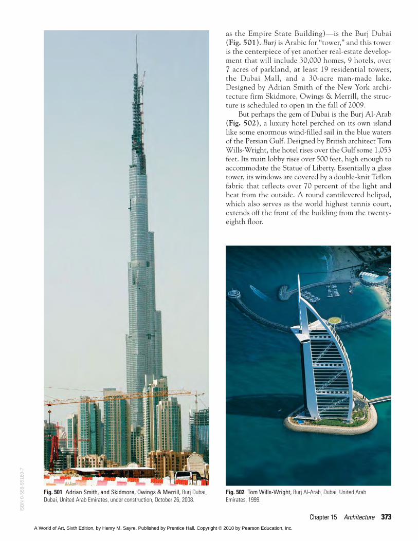
as the Empire State Building)—is the Burj Dubai(Fig. 501). Burj is Arabic for “tower,” and this toweris the centerpiece of yet another real-estate develop-ment that will include 30,000 homes, 9 hotels, over7 acres of parkland, at least 19 residential towers,the Dubai Mall, and a 30-acre man-made lake.Designed by Adrian Smith of the New York archi-tecture firm Skidmore, Owings & Merrill, the struc-ture is scheduled to open in the fall of 2009.
But perhaps the gem of Dubai is the Burj Al-Arab(Fig. 502), a luxury hotel perched on its own islandlike some enormous wind-filled sail in the blue watersof the Persian Gulf. Designed by British architect TomWills-Wright, the hotel rises over the Gulf some 1,053feet. Its main lobby rises over 500 feet, high enough toaccommodate the Statue of Liberty. Essentially a glasstower, its windows are covered by a double-knit Teflonfabric that reflects over 70 percent of the light andheat from the outside. A round cantilevered helipad,which also serves as the world highest tennis court,extends off the front of the building from the twenty-eighth floor.
Chapter 15 Architecture 373Chapter 15 Architecture 373
Fig. 501 Adrian Smith, and Skidmore, Owings & Merrill, Burj Dubai,Dubai, United Arab Emirates, under construction, October 26, 2008.
Fig. 502 Tom Wills-Wright, Burj Al-Arab, Dubai, United Arab Emirates, 1999.
ISB
N 0
-558
-551
80-7
A World of Art, Sixth Edition, by Henry M. Sayre. Published by Prentice Hall. Copyright © 2010 by Pearson Education, Inc.
374 Part 3 The Fine Arts Media
“GREEN” ARCHITECTURE
Aside from the fact that they take steps to allay, insome measure, the heat of the desert, and thus cutdown on energy consumption, the high rises of Dubaiare not just monumental, but monumentally at oddswith the environment. It is not just that they embodya drive toward a density of population that their desertenvirons do not seem capable of sustaining, but, situ-ated as they are in the oil-rich Arab world, they couldbe said to symbolize the unbridled consumption offossil fuels that has contributed, in no small part, toglobal warming. In response to the direction in archi-tecture that buildings such as the Dubai towers repre-sent, a different practice, more environmentallyfriendly and sustainable, has developed—so-calledgreen architecture.
One of the masterpieces of green architecture isRenzo Piano’s Jean-Marie Tjibaou Cultural Center inNew Caledonia (see Fig. 10). As Piano’s design sug-gests, green architecture is characterized by a numberof different principles, but usually only some of theseprinciples are realized in a given project:
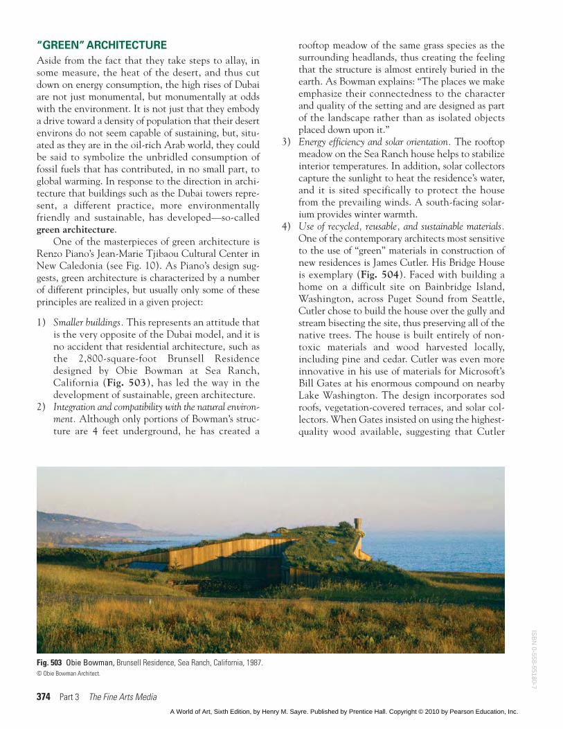
1) Smaller buildings. This represents an attitude thatis the very opposite of the Dubai model, and it isno accident that residential architecture, such asthe 2,800-square-foot Brunsell Residencedesigned by Obie Bowman at Sea Ranch,California (Fig. 503), has led the way in thedevelopment of sustainable, green architecture.
2) Integration and compatibility with the natural environ-ment. Although only portions of Bowman’s struc-ture are 4 feet underground, he has created a
rooftop meadow of the same grass species as thesurrounding headlands, thus creating the feelingthat the structure is almost entirely buried in theearth. As Bowman explains: “The places we makeemphasize their connectedness to the characterand quality of the setting and are designed as partof the landscape rather than as isolated objectsplaced down upon it.”
3) Energy efficiency and solar orientation. The rooftopmeadow on the Sea Ranch house helps to stabilizeinterior temperatures. In addition, solar collectorscapture the sunlight to heat the residence’s water,and it is sited specifically to protect the housefrom the prevailing winds. A south-facing solar-ium provides winter warmth.
4) Use of recycled, reusable, and sustainable materials.One of the contemporary architects most sensitiveto the use of “green” materials in construction ofnew residences is James Cutler. His Bridge Houseis exemplary (Fig. 504). Faced with building ahome on a difficult site on Bainbridge Island,Washington, across Puget Sound from Seattle,Cutler chose to build the house over the gully andstream bisecting the site, thus preserving all of thenative trees. The house is built entirely of non-toxic materials and wood harvested locally,including pine and cedar. Cutler was even moreinnovative in his use of materials for Microsoft’sBill Gates at his enormous compound on nearbyLake Washington. The design incorporates sodroofs, vegetation-covered terraces, and solar col-lectors. When Gates insisted on using the highest-quality wood available, suggesting that Cutler
Fig. 503 Obie Bowman, Brunsell Residence, Sea Ranch, California, 1987.© Obie Bowman Architect.
ISB
N 0-558-55180-7
A World of Art, Sixth Edition, by Henry M. Sayre. Published by Prentice Hall. Copyright © 2010 by Pearson Education, Inc.
Chapter 15 Architecture 375
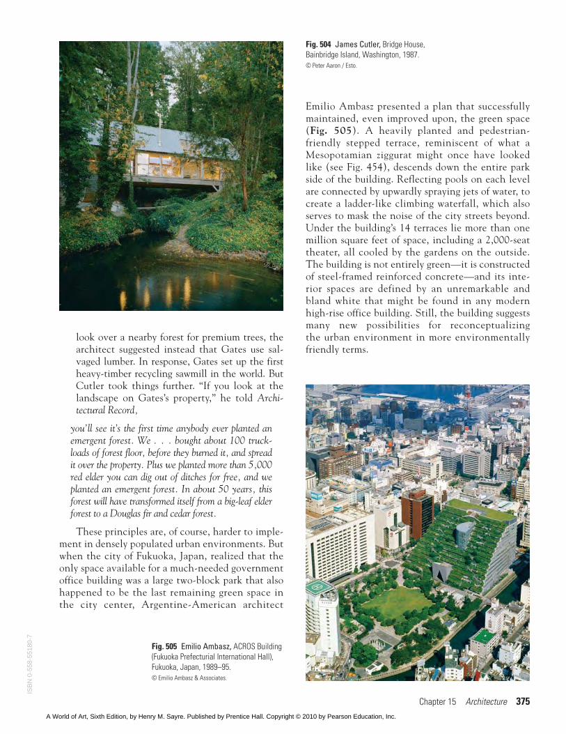
Fig. 504 James Cutler, Bridge House,Bainbridge Island, Washington, 1987.© Peter Aaron / Esto.
Fig. 505 Emilio Ambasz, ACROS Building(Fukuoka Prefecturial International Hall),Fukuoka, Japan, 1989–95.© Emilio Ambasz & Associates.
look over a nearby forest for premium trees, thearchitect suggested instead that Gates use sal-vaged lumber. In response, Gates set up the firstheavy-timber recycling sawmill in the world. ButCutler took things further. “If you look at thelandscape on Gates’s property,” he told Archi-tectural Record,
you’ll see it’s the first time anybody ever planted anemergent forest. We . . . bought about 100 truck-loads of forest floor, before they burned it, and spreadit over the property. Plus we planted more than 5,000red elder you can dig out of ditches for free, and weplanted an emergent forest. In about 50 years, thisforest will have transformed itself from a big-leaf elderforest to a Douglas fir and cedar forest.
These principles are, of course, harder to imple-ment in densely populated urban environments. Butwhen the city of Fukuoka, Japan, realized that theonly space available for a much-needed governmentoffice building was a large two-block park that alsohappened to be the last remaining green space inthe city center, Argentine-American architect
Emilio Ambasz presented a plan that successfullymaintained, even improved upon, the green space(Fig. 505). A heavily planted and pedestrian-friendly stepped terrace, reminiscent of what aMesopotamian ziggurat might once have lookedlike (see Fig. 454), descends down the entire parkside of the building. Reflecting pools on each levelare connected by upwardly spraying jets of water, tocreate a ladder-like climbing waterfall, which alsoserves to mask the noise of the city streets beyond.Under the building’s 14 terraces lie more than onemillion square feet of space, including a 2,000-seattheater, all cooled by the gardens on the outside.The building is not entirely green—it is constructedof steel-framed reinforced concrete—and its inte-rior spaces are defined by an unremarkable andbland white that might be found in any modernhigh-rise office building. Still, the building suggestsmany new possibilities for reconceptualizingthe urban environment in more environmentallyfriendly terms.
ISB
N 0
-558
-551
80-7
A World of Art, Sixth Edition, by Henry M. Sayre. Published by Prentice Hall. Copyright © 2010 by Pearson Education, Inc.
COMMUNITY LIFE
However lovely we find the Seagram Building, theuniformity of its grid-like facade, in the hands of less-skillful architects, came to represent, for many, theimpersonality and anonymity of urban life. The sky-scraper became, by the 1960s, the embodiment of con-formity and mediocrity in the modern world. Ratherthan a symbol of community, it became a symbol ofhuman anonymity and loneliness.
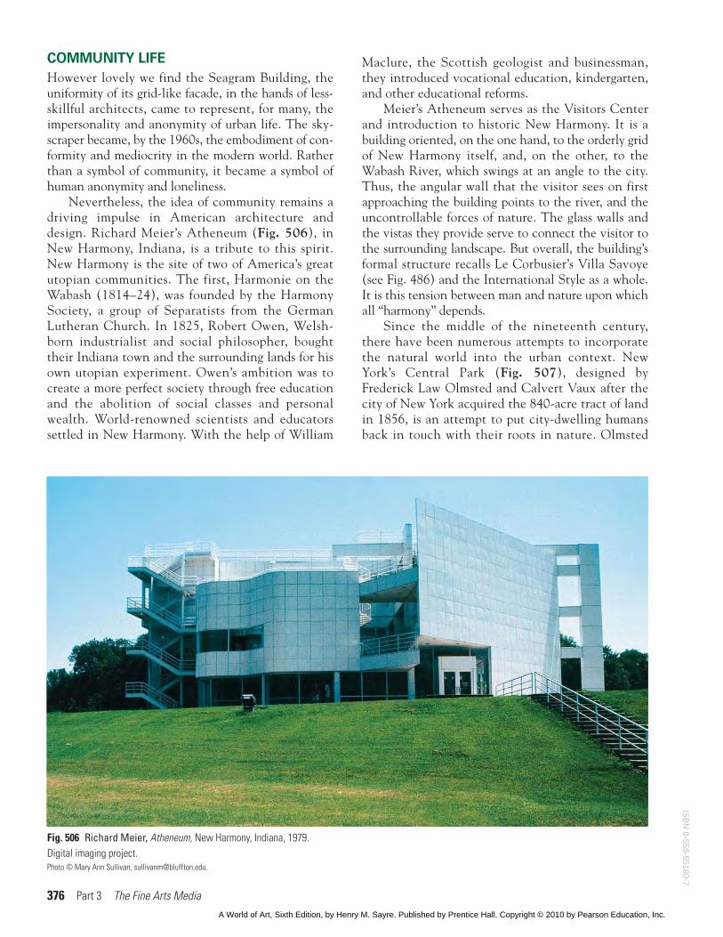
Nevertheless, the idea of community remains adriving impulse in American architecture anddesign. Richard Meier’s Atheneum (Fig. 506), inNew Harmony, Indiana, is a tribute to this spirit.New Harmony is the site of two of America’s greatutopian communities. The first, Harmonie on theWabash (1814–24), was founded by the HarmonySociety, a group of Separatists from the GermanLutheran Church. In 1825, Robert Owen, Welsh-born industrialist and social philosopher, boughttheir Indiana town and the surrounding lands for hisown utopian experiment. Owen’s ambition was tocreate a more perfect society through free educationand the abolition of social classes and personalwealth. World-renowned scientists and educatorssettled in New Harmony. With the help of William
Maclure, the Scottish geologist and businessman,they introduced vocational education, kindergarten,and other educational reforms.
Meier’s Atheneum serves as the Visitors Centerand introduction to historic New Harmony. It is abuilding oriented, on the one hand, to the orderly gridof New Harmony itself, and, on the other, to theWabash River, which swings at an angle to the city.Thus, the angular wall that the visitor sees on firstapproaching the building points to the river, and theuncontrollable forces of nature. The glass walls andthe vistas they provide serve to connect the visitor tothe surrounding landscape. But overall, the building’sformal structure recalls Le Corbusier’s Villa Savoye(see Fig. 486) and the International Style as a whole.It is this tension between man and nature upon whichall “harmony” depends.
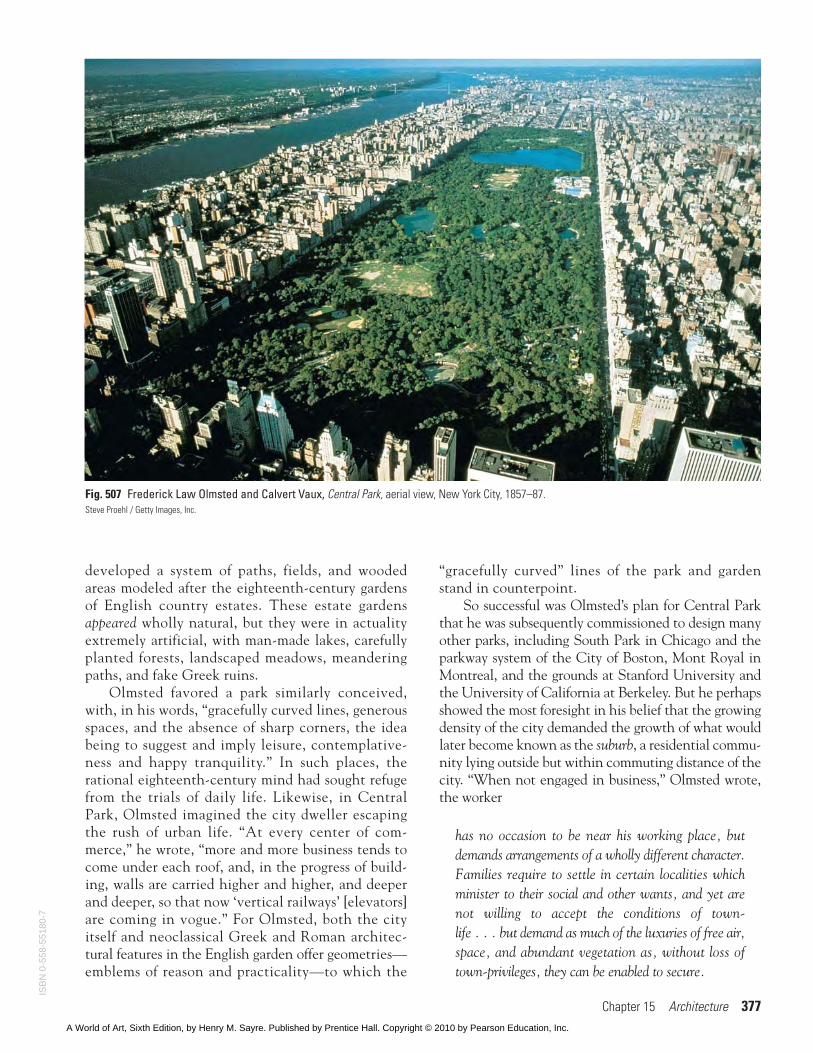
Since the middle of the nineteenth century,there have been numerous attempts to incorporatethe natural world into the urban context. NewYork’s Central Park (Fig. 507), designed byFrederick Law Olmsted and Calvert Vaux after thecity of New York acquired the 840-acre tract of landin 1856, is an attempt to put city-dwelling humansback in touch with their roots in nature. Olmsted
376 Part 3 The Fine Arts Media
Fig. 506 Richard Meier, Atheneum, New Harmony, Indiana, 1979.Digital imaging project.Photo © Mary Ann Sullivan, [email protected].
ISB
N 0-558-55180-7
A World of Art, Sixth Edition, by Henry M. Sayre. Published by Prentice Hall. Copyright © 2010 by Pearson Education, Inc.
Chapter 15 Architecture 377
Fig. 507 Frederick Law Olmsted and Calvert Vaux, Central Park, aerial view, New York City, 1857–87.Steve Proehl / Getty Images, Inc.
developed a system of paths, fields, and woodedareas modeled after the eighteenth-century gardensof English country estates. These estate gardensappeared wholly natural, but they were in actualityextremely artificial, with man-made lakes, carefullyplanted forests, landscaped meadows, meanderingpaths, and fake Greek ruins.
Olmsted favored a park similarly conceived,with, in his words, “gracefully curved lines, generousspaces, and the absence of sharp corners, the ideabeing to suggest and imply leisure, contemplative-ness and happy tranquility.” In such places, therational eighteenth-century mind had sought refugefrom the trials of daily life. Likewise, in CentralPark, Olmsted imagined the city dweller escapingthe rush of urban life. “At every center of com-merce,” he wrote, “more and more business tends tocome under each roof, and, in the progress of build-ing, walls are carried higher and higher, and deeperand deeper, so that now ‘vertical railways’ [elevators]are coming in vogue.” For Olmsted, both the cityitself and neoclassical Greek and Roman architec-tural features in the English garden offer geometries—emblems of reason and practicality—to which the
“gracefully curved” lines of the park and gardenstand in counterpoint.
So successful was Olmsted’s plan for Central Parkthat he was subsequently commissioned to design manyother parks, including South Park in Chicago and theparkway system of the City of Boston, Mont Royal inMontreal, and the grounds at Stanford University andthe University of California at Berkeley. But he perhapsshowed the most foresight in his belief that the growingdensity of the city demanded the growth of what wouldlater become known as the suburb, a residential commu-nity lying outside but within commuting distance of thecity. “When not engaged in business,” Olmsted wrote,the worker
has no occasion to be near his working place, butdemands arrangements of a wholly different character.Families require to settle in certain localities whichminister to their social and other wants, and yet arenot willing to accept the conditions of town-life . . . but demand as much of the luxuries of free air,space, and abundant vegetation as, without loss oftown-privileges, they can be enabled to secure.
ISB
N 0
-558
-551
80-7
A World of Art, Sixth Edition, by Henry M. Sayre. Published by Prentice Hall. Copyright © 2010 by Pearson Education, Inc.
378 Part 3 The Fine Arts Media
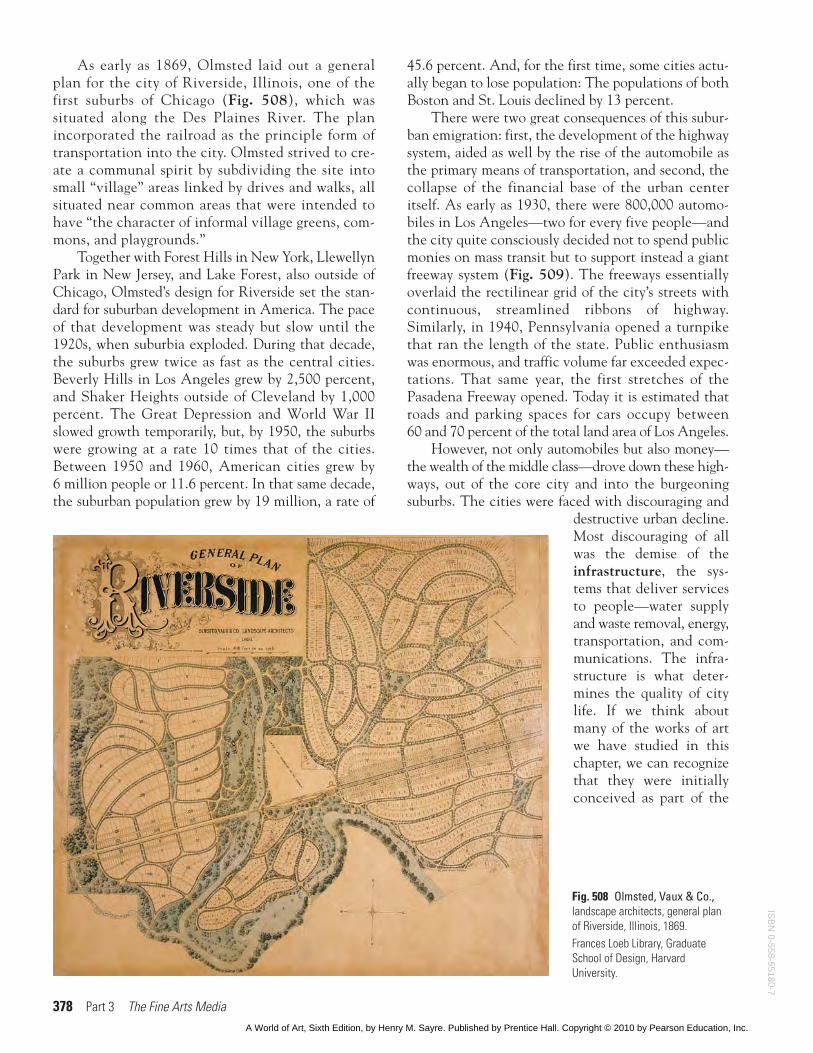
As early as 1869, Olmsted laid out a generalplan for the city of Riverside, Illinois, one of thefirst suburbs of Chicago (Fig. 508), which wassituated along the Des Plaines River. The planincorporated the railroad as the principle form oftransportation into the city. Olmsted strived to cre-ate a communal spirit by subdividing the site intosmall “village” areas linked by drives and walks, allsituated near common areas that were intended tohave “the character of informal village greens, com-mons, and playgrounds.”
Together with Forest Hills in New York, LlewellynPark in New Jersey, and Lake Forest, also outside ofChicago, Olmsted’s design for Riverside set the stan-dard for suburban development in America. The paceof that development was steady but slow until the1920s, when suburbia exploded. During that decade,the suburbs grew twice as fast as the central cities.Beverly Hills in Los Angeles grew by 2,500 percent,and Shaker Heights outside of Cleveland by 1,000percent. The Great Depression and World War IIslowed growth temporarily, but, by 1950, the suburbswere growing at a rate 10 times that of the cities.Between 1950 and 1960, American cities grew by6 million people or 11.6 percent. In that same decade,the suburban population grew by 19 million, a rate of
45.6 percent. And, for the first time, some cities actu-ally began to lose population: The populations of bothBoston and St. Louis declined by 13 percent.
There were two great consequences of this subur-ban emigration: first, the development of the highwaysystem, aided as well by the rise of the automobile asthe primary means of transportation, and second, thecollapse of the financial base of the urban centeritself. As early as 1930, there were 800,000 automo-biles in Los Angeles—two for every five people—andthe city quite consciously decided not to spend publicmonies on mass transit but to support instead a giantfreeway system (Fig. 509). The freeways essentiallyoverlaid the rectilinear grid of the city’s streets withcontinuous, streamlined ribbons of highway.Similarly, in 1940, Pennsylvania opened a turnpikethat ran the length of the state. Public enthusiasmwas enormous, and traffic volume far exceeded expec-tations. That same year, the first stretches of thePasadena Freeway opened. Today it is estimated thatroads and parking spaces for cars occupy between 60 and 70 percent of the total land area of Los Angeles.
However, not only automobiles but also money—the wealth of the middle class—drove down these high-ways, out of the core city and into the burgeoningsuburbs. The cities were faced with discouraging and
destructive urban decline.Most discouraging of allwas the demise of theinfrastructure, the sys-tems that deliver servicesto people—water supplyand waste removal, energy,transportation, and com-munications. The infra-structure is what deter-mines the quality of citylife. If we think aboutmany of the works of artwe have studied in thischapter, we can recognizethat they were initiallyconceived as part of the
Fig. 508 Olmsted, Vaux & Co.,landscape architects, general planof Riverside, Illinois, 1869.Frances Loeb Library, GraduateSchool of Design, HarvardUniversity.
ISB
N 0-558-55180-7
A World of Art, Sixth Edition, by Henry M. Sayre. Published by Prentice Hall. Copyright © 2010 by Pearson Education, Inc.
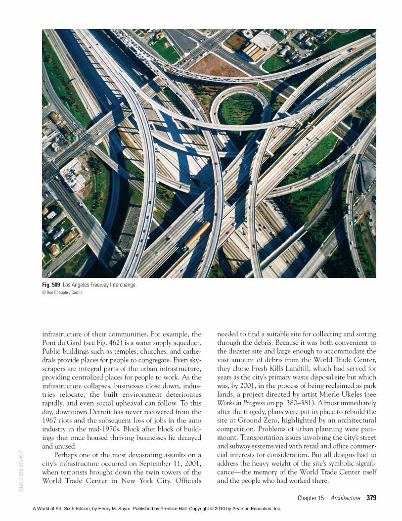
infrastructure of their communities. For example, thePont du Gard (see Fig. 462) is a water supply aqueduct.Public buildings such as temples, churches, and cathe-drals provide places for people to congregate. Even sky-scrapers are integral parts of the urban infrastructure,providing centralized places for people to work. As theinfrastructure collapses, businesses close down, indus-tries relocate, the built environment deterioratesrapidly, and even social upheaval can follow. To thisday, downtown Detroit has never recovered from the1967 riots and the subsequent loss of jobs in the autoindustry in the mid-1970s. Block after block of build-ings that once housed thriving businesses lie decayedand unused.
Perhaps one of the most devastating assaults on acity’s infrastructure occurred on September 11, 2001,when terrorists brought down the twin towers of theWorld Trade Center in New York City. Officials
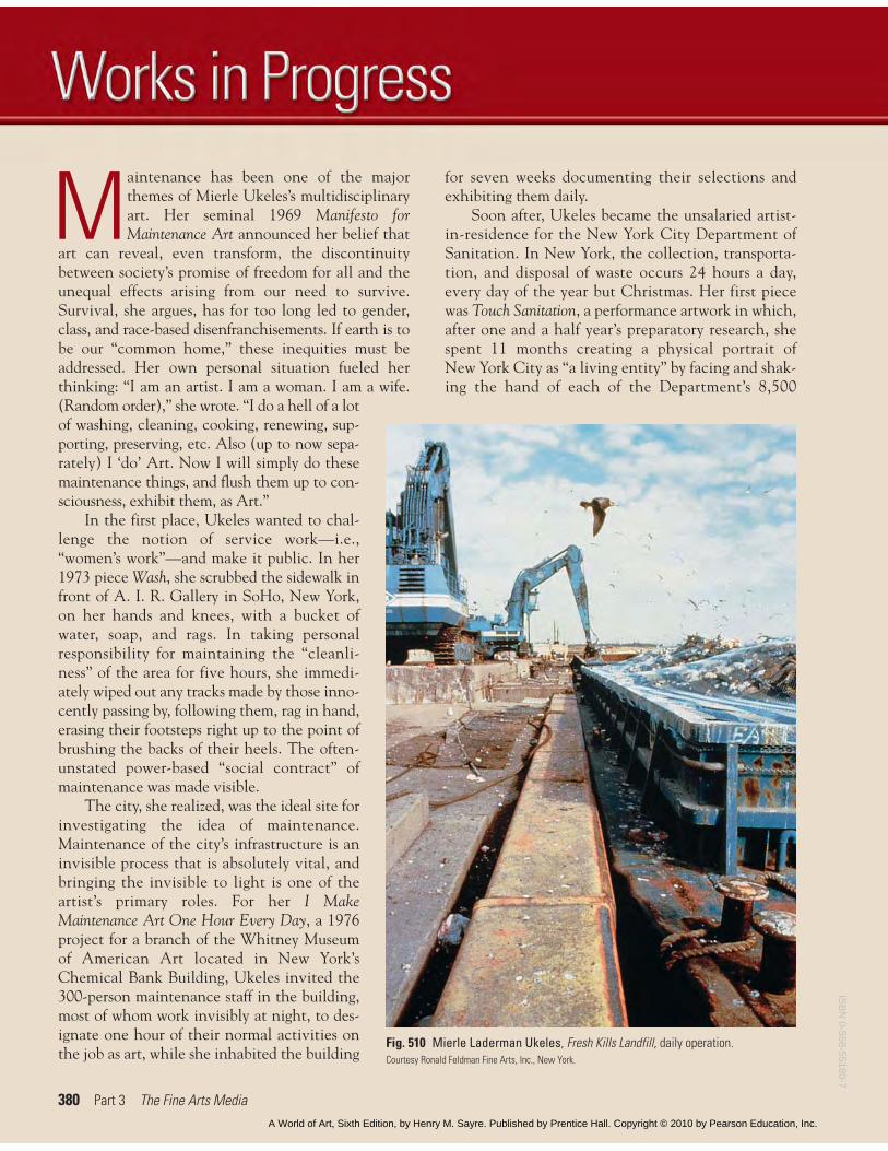
needed to find a suitable site for collecting and sortingthrough the debris. Because it was both convenient tothe disaster site and large enough to accommodate thevast amount of debris from the World Trade Center,they chose Fresh Kills Landfill, which had served foryears as the city’s primary waste disposal site but whichwas, by 2001, in the process of being reclaimed as parklands, a project directed by artist Mierle Ukeles (seeWorks in Progress on pp. 380–381). Almost immediatelyafter the tragedy, plans were put in place to rebuild thesite at Ground Zero, highlighted by an architecturalcompetition. Problems of urban planning were para-mount. Transportation issues involving the city’s streetand subway systems vied with retail and office commer-cial interests for consideration. But all designs had toaddress the heavy weight of the site’s symbolic signifi-cance—the memory of the World Trade Center itselfand the people who had worked there.
Chapter 15 Architecture 379
Fig. 509 Los Angeles Freeway Interchange.© Ron Chapple / Corbis.
ISB
N 0
-558
-551
80-7
A World of Art, Sixth Edition, by Henry M. Sayre. Published by Prentice Hall. Copyright © 2010 by Pearson Education, Inc.
380 Part 3 The Fine Arts Media
Maintenance has been one of the majorthemes of Mierle Ukeles’s multidisciplinaryart. Her seminal 1969 Manifesto forMaintenance Art announced her belief that
art can reveal, even transform, the discontinuitybetween society’s promise of freedom for all and theunequal effects arising from our need to survive.Survival, she argues, has for too long led to gender,class, and race-based disenfranchisements. If earth is tobe our “common home,” these inequities must beaddressed. Her own personal situation fueled herthinking: “I am an artist. I am a woman. I am a wife.(Random order),” she wrote. “I do a hell of a lotof washing, cleaning, cooking, renewing, sup-porting, preserving, etc. Also (up to now sepa-rately) I ‘do’ Art. Now I will simply do thesemaintenance things, and flush them up to con-sciousness, exhibit them, as Art.”
In the first place, Ukeles wanted to chal-lenge the notion of service work—i.e.,“women’s work”—and make it public. In her1973 piece Wash, she scrubbed the sidewalk infront of A. I. R. Gallery in SoHo, New York,on her hands and knees, with a bucket ofwater, soap, and rags. In taking personalresponsibility for maintaining the “cleanli-ness” of the area for five hours, she immedi-ately wiped out any tracks made by those inno-cently passing by, following them, rag in hand,erasing their footsteps right up to the point ofbrushing the backs of their heels. The often-unstated power-based “social contract” ofmaintenance was made visible.
The city, she realized, was the ideal site forinvestigating the idea of maintenance.Maintenance of the city’s infrastructure is aninvisible process that is absolutely vital, andbringing the invisible to light is one of theartist’s primary roles. For her I MakeMaintenance Art One Hour Every Day, a 1976project for a branch of the Whitney Museumof American Art located in New York’sChemical Bank Building, Ukeles invited the300-person maintenance staff in the building,most of whom work invisibly at night, to des-ignate one hour of their normal activities onthe job as art, while she inhabited the building
for seven weeks documenting their selections andexhibiting them daily.
Soon after, Ukeles became the unsalaried artist-in-residence for the New York City Department ofSanitation. In New York, the collection, transporta-tion, and disposal of waste occurs 24 hours a day,every day of the year but Christmas. Her first piecewas Touch Sanitation, a performance artwork in which,after one and a half year’s preparatory research, shespent 11 months creating a physical portrait ofNew York City as “a living entity” by facing and shak-ing the hand of each of the Department’s 8,500
Fig. 510 Mierle Laderman Ukeles, Fresh Kills Landfill, daily operation.Courtesy Ronald Feldman Fine Arts, Inc., New York.
ISB
N 0-558-55180-7
A World of Art, Sixth Edition, by Henry M. Sayre. Published by Prentice Hall. Copyright © 2010 by Pearson Education, Inc.
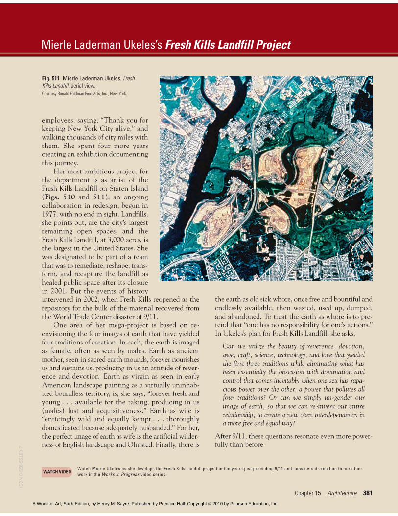
employees, saying, “Thank you forkeeping New York City alive,” andwalking thousands of city miles withthem. She spent four more yearscreating an exhibition documentingthis journey.
Her most ambitious project forthe department is as artist of theFresh Kills Landfill on Staten Island(Figs. 510 and 511), an ongoingcollaboration in redesign, begun in1977, with no end in sight. Landfills,she points out, are the city’s largestremaining open spaces, and theFresh Kills Landfill, at 3,000 acres, isthe largest in the United States. Shewas designated to be part of a teamthat was to remediate, reshape, trans-form, and recapture the landfill ashealed public space after its closurein 2001. But the events of historyintervened in 2002, when Fresh Kills reopened as therepository for the bulk of the material recovered fromthe World Trade Center disaster of 9/11.
One area of her mega-project is based on re-envisioning the four images of earth that have yieldedfour traditions of creation. In each, the earth is imagedas female, often as seen by males. Earth as ancientmother, seen in sacred earth mounds, forever nourishesus and sustains us, producing in us an attitude of rever-ence and devotion. Earth as virgin as seen in earlyAmerican landscape painting as a virtually uninhab-ited boundless territory, is, she says, “forever fresh andyoung . . . available for the taking, producing in us(males) lust and acquisitiveness.” Earth as wife is“enticingly wild and equally kempt . . . thoroughlydomesticated because adequately husbanded.” For her,the perfect image of earth as wife is the artificial wilder-ness of English landscape and Olmsted. Finally, there is
the earth as old sick whore, once free and bountiful andendlessly available, then wasted, used up, dumped,and abandoned. To treat the earth as whore is to pre-tend that “one has no responsibility for one’s actions.”In Ukeles’s plan for Fresh Kills Landfill, she asks,
Can we utilize the beauty of reverence, devotion,awe, craft, science, technology, and love that yieldedthe first three traditions while eliminating what hasbeen essentially the obsession with domination andcontrol that comes inevitably when one sex has rapa-cious power over the other, a power that pollutes allfour traditions? Or can we simply un-gender ourimage of earth, so that we can re-invent our entirerelationship, to create a new open interdependency ina more free and equal way?
After 9/11, these questions resonate even more power-fully than before.
Mierle Laderman Ukeles’s Fresh Kills Landfill Project
Chapter 15 Architecture 381
Fig. 511 Mierle Laderman Ukeles, FreshKills Landfill, aerial view.Courtesy Ronald Feldman Fine Arts, Inc., New York.
Watch Mierle Ukeles as she develops the Fresh Kills Landfill project in the years just preceding 9/11 and considers its relation to her otherwork in the Works in Progress video series.WATCH VIDEO
ISB
N 0
-558
-551
80-7
A World of Art, Sixth Edition, by Henry M. Sayre. Published by Prentice Hall. Copyright © 2010 by Pearson Education, Inc.
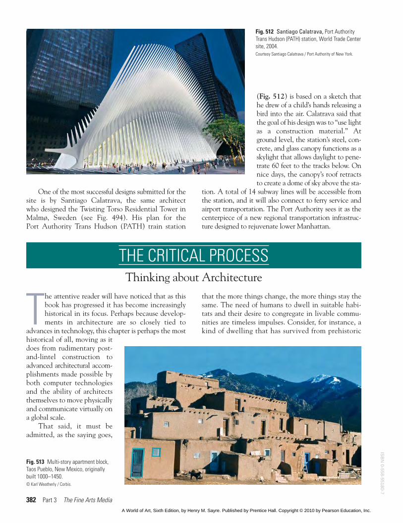
(Fig. 512) is based on a sketch thathe drew of a child’s hands releasing abird into the air. Calatrava said thatthe goal of his design was to “use lightas a construction material.” Atground level, the station’s steel, con-crete, and glass canopy functions as askylight that allows daylight to pene-trate 60 feet to the tracks below. Onnice days, the canopy’s roof retractsto create a dome of sky above the sta-
tion. A total of 14 subway lines will be accessible fromthe station, and it will also connect to ferry service andairport transportation. The Port Authority sees it as thecenterpiece of a new regional transportation infrastruc-ture designed to rejuvenate lower Manhattan.
382 Part 3 The Fine Arts Media
Fig. 512 Santiago Calatrava, Port AuthorityTrans Hudson (PATH) station, World Trade Centersite, 2004.Courtesy Santiago Calatrava / Port Authority of New York.
THE CRITICAL PROCESS Thinking about Architecture
The attentive reader will have noticed that as thisbook has progressed it has become increasinglyhistorical in its focus. Perhaps because develop-ments in architecture are so closely tied to
advances in technology, this chapter is perhaps the mosthistorical of all, moving as itdoes from rudimentary post-and-lintel construction toadvanced architectural accom-plishments made possible byboth computer technologiesand the ability of architectsthemselves to move physicallyand communicate virtually ona global scale.
That said, it must beadmitted, as the saying goes,
that the more things change, the more things stay thesame. The need of humans to dwell in suitable habi-tats and their desire to congregate in livable commu-nities are timeless impulses. Consider, for instance, akind of dwelling that has survived from prehistoric
Fig. 513 Multi-story apartment block,Taos Pueblo, New Mexico, originallybuilt 1000–1450.© Karl Weatherly / Corbis.
One of the most successful designs submitted for thesite is by Santiago Calatrava, the same architectwho designed the Twisting Torso Residential Tower inMalmø, Sweden (see Fig. 494). His plan for thePort Authority Trans Hudson (PATH) train station
ISB
N 0-558-55180-7
A World of Art, Sixth Edition, by Henry M. Sayre. Published by Prentice Hall. Copyright © 2010 by Pearson Education, Inc.
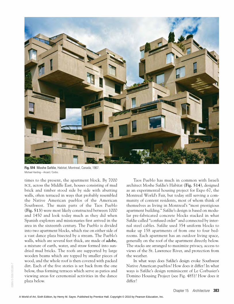
times to the present, the apartment block. By 7000BCE, across the Middle East, houses consisting of mudbrick and timber stood side by side with abuttingwalls, often terraced in ways that probably resembledthe Native American pueblos of the AmericanSouthwest. The main parts of the Taos Pueblo(Fig. 513) were most likely constructed between 1000and 1450 and look today much as they did whenSpanish explorers and missionaries first arrived in thearea in the sixteenth century. The Pueblo is dividedinto two apartment blocks, which rise on either side ofa vast dance plaza bisected by a stream. The Pueblo’swalls, which are several feet thick, are made of adobe,a mixture of earth, water, and straw formed into sun-dried mud bricks. The roofs are supported by largewooden beams which are topped by smaller pieces ofwood, and the whole roof is then covered with packeddirt. Each of the five stories is set back from the onebelow, thus forming terraces which serve as patios andviewing areas for ceremonial activities in the danceplaza below.
Taos Pueblo has much in common with Israeliarchitect Moshe Safdie’s Habitat (Fig. 514), designedas an experimental housing project for Expo 67, theMontreal World’s Fair, but today still serving a com-munity of content residents, most of whom think ofthemselves as living in Montreal’s “most prestigiousapartment building.” Safdie’s design is based on modu-lar pre-fabricated concrete blocks stacked in whatSafdie called “confused order” and connected by inter-nal steel cables. Safdie used 354 uniform blocks tomake up 158 apartments of from one to four bed-rooms. Each apartment has an outdoor living space,generally on the roof of the apartment directly below.The stacks are arranged to maximize privacy, access toviews of the St. Lawrence River, and protection fromthe weather.
In what ways does Safdie’s design evoke SouthwestNative American pueblos? How does it differ? In whatways is Safdie’s design reminiscent of Le Corbusier’sDomino Housing Project (see Fig. 485)? How does itdiffer?
Chapter 15 Architecture 383
Fig. 514 Moshe Safdie, Habitat, Montreal, Canada, 1967.Michael Harding—Arcaid / Corbis.
ISB
N 0
-558
-551
80-7
A World of Art, Sixth Edition, by Henry M. Sayre. Published by Prentice Hall. Copyright © 2010 by Pearson Education, Inc.