Embed Size (px)
Citation preview

EnglishOriginal Instructions 12-2018 A031C172 (Issue 6)
InstallationInstallation ManualManual
Onan Generator Set for RV
HGJBB (Spec A-B)


iA031C172 (Issue 6) Copyright © 2018 Cummins Inc.
Table of Contents
1. IMPORTANT SAFETY INSTRUCTIONS ....................................................................................... 11.1 Overview ................................................................................................................................. 11.2 Warning, Caution, and Note Styles Used in This Manual ..................................................... 11.3 General Safety Precautions.................................................................................................... 11.4 Automatic Generator Start Control Hazards ........................................................................... 31.5 Electrical Shock and Arc Flash Can Cause Severe Personal Injury or Death ....................... 31.6 Generator Voltage Is Deadly .................................................................................................. 31.7 Engine Exhaust/Carbon Monoxide Is Deadly ......................................................................... 41.8 Fuel Is Flammable and Explosive........................................................................................... 51.9 Battery Gas Is Explosive......................................................................................................... 51.10 Moving Parts Can Cause Severe Personal Injury or Death ................................................. 51.11 CARB .................................................................................................................................... 6
2. INTRODUCTION............................................................................................................................ 72.1 About This Manual.................................................................................................................. 72.2 Related Literature ................................................................................................................... 72.3 Installation Codes and Standards for Safety .......................................................................... 82.4 Electromagnetic Compatibility Compliance............................................................................. 92.5 Specifications.......................................................................................................................... 9
2.5.1 Gasoline Model Specifications..................................................................................... 92.5.2 LPG Model Specifications.......................................................................................... 10
2.6 List of Acronyms ................................................................................................................... 11
3. LOCATION, MOUNTING, AND VENTILATION........................................................................... 153.1 Location ................................................................................................................................ 15
3.1.1 Typical Generator Set Locations - Class A RV.......................................................... 163.1.2 Typical Generator Set Locations - Class C RV ......................................................... 163.1.3 Typical Generator Set Locations - Class B Van ........................................................ 173.1.4 Typical Generator Set Locations - Pickup Truck Camper ......................................... 17
3.2 Mounting ............................................................................................................................... 173.2.1 Below Floor Mounting ................................................................................................ 183.2.2 Insulating Materials .................................................................................................... 183.2.3 Fire and Exhaust Barriers .......................................................................................... 18
3.3 Ventilation ............................................................................................................................. 19
4. EXHAUST CONNECTIONS......................................................................................................... 214.1 Tailpipe Installation ............................................................................................................... 214.2 Vehicle Clearances - Class A RV ......................................................................................... 244.3 Vehicle Clearances - Class B Van........................................................................................ 254.4 Vehicle Clearances - Pickup Truck Camper......................................................................... 25
5. FUEL CONNECTIONS................................................................................................................. 275.1 Gasoline Motorized ............................................................................................................... 27

Table of Contents 12-2018
ii A031C172 (Issue 6)Copyright © 2018 Cummins Inc.
5.1.1 Fuel Hoses................................................................................................................. 285.1.2 Fuel Lines................................................................................................................... 295.1.3 Routing Fuel Lines ..................................................................................................... 29
5.2 LPG....................................................................................................................................... 30
6. ELECTRICAL CONNECTIONS.................................................................................................... 336.1 AC Power Output Connections............................................................................................. 33
6.1.1 Wiring Methods .......................................................................................................... 346.1.2 Connecting to Shore Power ....................................................................................... 34
6.2 Remote Control Connections................................................................................................ 356.3 Starting Battery Connections ................................................................................................ 37
6.3.1 Battery Compartment................................................................................................. 376.3.2 Battery Cable Sizes ................................................................................................... 376.3.3 Battery Cables............................................................................................................ 376.3.4 Battery Cable Connections at the Generator Set ...................................................... 396.3.5 Generator Set (Equipment) Grounding Screw........................................................... 40
7. INSTALLATION REVIEW AND STARTUP.................................................................................. 417.1 Installation Review................................................................................................................ 417.2 Startup .................................................................................................................................. 417.3 Hot Air Recirculation Test ..................................................................................................... 42
7.3.1 Test Method ............................................................................................................... 427.3.2 Test Results ............................................................................................................... 43
APPENDIX A. WIRING DIAGRAMS................................................................................................. 45A.0 Wiring Diagram - 50 and 60 Hz............................................................................................ 47
APPENDIX B. OUTLINE DRAWINGS .............................................................................................. 49B.0 Outline Drawing A034N392.................................................................................................. 51

1A031C172 (Issue 6) Copyright © 2018 Cummins Inc.
1 Important Safety Instructions
1.1 OverviewThoroughly read the Operator Manual before operating the generator set. It contains important instructionsthat should be followed during operation and maintenance. Safe operation and top performance can onlybe achieved when equipment is properly operated and maintained. The owners and operators of thegenerator set are solely responsible for its safe operation.
Generator set operation, maintenance, and installation must comply with all applicable local, state, andfederal codes and regulations. Electricity, fuel, exhaust, moving parts, and batteries present hazards whichcan result in severe personal injury or death. Only trained and experienced personnel with knowledge offuels, electricity, and machinery hazards should perform generator set installation or adjustmentprocedures; or remove, dismantle, or dispose of the generator set.
1.2 Warning, Caution, and Note Styles Used in ThisManualThe following safety styles and symbols found throughout this manual indicate potentially hazardousconditions to the operator, service personnel, or equipment.
DANGERIndicates a hazardous situation that, if not avoided, will result in death or serious injury.
WARNINGIndicates a hazardous situation that, if not avoided, could result in death or serious injury.
CAUTIONIndicates a hazardous situation that, if not avoided, could result in minor or moderate injury.
NOTICEIndicates information considered important, but not hazard-related (e.g., messages relating toproperty damage).
1.3 General Safety PrecautionsWARNING
Operation of equipment is unsafe when mentally or physically fatigued. Do not operateequipment in this condition, or after consuming any alcohol or drug.
1. Important Safety Instructions 12-2018
2 A031C172 (Issue 6)Copyright © 2018 Cummins Inc.
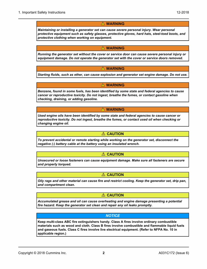
WARNINGMaintaining or installing a generator set can cause severe personal injury. Wear personalprotective equipment such as safety glasses, protective gloves, hard hats, steel-toed boots, andprotective clothing when working on equipment.
WARNINGRunning the generator set without the cover or service door can cause severe personal injury orequipment damage. Do not operate the generator set with the cover or service doors removed.
WARNINGStarting fluids, such as ether, can cause explosion and generator set engine damage. Do not use.
WARNINGBenzene, found in some fuels, has been identified by some state and federal agencies to causecancer or reproductive toxicity. Do not ingest, breathe the fumes, or contact gasoline whenchecking, draining, or adding gasoline.
WARNINGUsed engine oils have been identified by some state and federal agencies to cause cancer orreproductive toxicity. Do not ingest, breathe the fumes, or contact used oil when checking orchanging engine oil.
CAUTIONTo prevent accidental or remote starting while working on the generator set, disconnect thenegative (-) battery cable at the battery using an insulated wrench.
CAUTIONUnsecured or loose fasteners can cause equipment damage. Make sure all fasteners are secureand properly torqued.
CAUTIONOily rags and other material can cause fire and restrict cooling. Keep the generator set, drip pan,and compartment clean.
CAUTIONAccumulated grease and oil can cause overheating and engine damage presenting a potentialfire hazard. Keep the generator set clean and repair any oil leaks promptly.
NOTICEKeep multi-class ABC fire extinguishers handy. Class A fires involve ordinary combustiblematerials such as wood and cloth. Class B fires involve combustible and flammable liquid fuelsand gaseous fuels. Class C fires involve live electrical equipment. (Refer to NFPA No. 10 inapplicable region.)

1. Important Safety Instructions12-2018
3A031C172 (Issue 6) Copyright © 2018 Cummins Inc.
1.4 Automatic Generator Start Control HazardsWARNING
Accidental starting can cause severe personal injury or death. Turn off the AGS wheneverperforming maintenance or service, when the vehicle is stored between uses, is awaiting service,or is parked in a garage or other confined area.
Unexpected starting may occur if the generator set is equipped with an inverter-charger or other AutomaticGenerator Start (AGS) control. This may cause exposure to:
• Unexpected generator starting
• Moving parts hazards
• Electric shock
• Exhaust carbon monoxide (CO)
1.5 Electrical Shock and Arc Flash Can Cause SeverePersonal Injury or Death
WARNINGElectrical shocks and arc flashes can cause severe personal injury or death. Adhere to thefollowing guidelines:
• Only qualified service personnel certified and authorized to work on power circuits shouldwork on exposed energized power circuits.
• All relevant service material must be available for any electrical work performed by certifiedservice personnel.
• Exposure to energized power circuits with potentials of 50 VAC or 75 VDC or higher poses asignificant risk of electrical shock and electrical arc flash.
• Refer to standard NFPA 70E, or equivalent safety standards in corresponding regions, fordetails of the dangers involved and for safety requirements.
1.6 Generator Voltage Is DeadlyWARNING
Improperly connected generator electrical output connections can cause equipment damage,severe personal injury, or death. Electrical connections must be made by a trained andexperienced electrician in accordance with applicable codes.
WARNINGImproper installations can cause equipment damage, severe personal injury, or death. Allinstallations must be conducted by trained and experienced personnel in accordance with theinstallation instructions and all applicable codes.

1. Important Safety Instructions 12-2018
4 A031C172 (Issue 6)Copyright © 2018 Cummins Inc.
WARNINGBack feed to shore power can cause electrocution and damage to equipment. The generator setmust not be connected to shore power or to any other source of electrical power. An approvedswitching device must be used to prevent interconnections.
WARNINGLive electrical equipment can cause electrocution. Use caution when working on live electricalequipment. Remove jewelry, make sure clothing and shoes are dry, stand on a dry woodenplatform or rubber insulating mat, and use tools with insulated handles.
1.7 Engine Exhaust/Carbon Monoxide Is DeadlyWARNING
Substances in exhaust gases have been identified by some state and federal agencies to causecancer or reproductive toxicity. Do not breathe in or come into contact with exhaust gases.
WARNINGCarbon monoxide is a poisonous gas. Inhalation of this gas can cause severe personal injury ordeath. Adhere to the following bullet points to make sure carbon monoxide is not being inhaledby occupants of the vehicle as well as others working on or around the generator set.
• Inspect for exhaust leaks, and test and confirm that all carbon monoxide detectors areworking in accordance with the manufacturer's instructions or owner's manual, prior toevery startup, and after every 8 hours of running.
• Never occupy the vehicle while the generator set is running unless the vehicle is equippedwith a working carbon monoxide detector.
• Never operate the generator set when the vehicle is in a confined space, such as a garage,basement, or building of any kind.
• Make sure the exhaust system is installed in accordance with the generator set installationmanual.
• Never use engine cooling air for heating a working or living space compartment.
Carbon Monoxide (CO) is odorless, colorless, tasteless, and non-irritating. It cannot be seen or smelled.Exposure, even to low levels of CO for a prolonged period can lead to asphyxiation (lack of oxygen).
Mild effects of CO poisoning include:
• headache
• dizziness
• drowsiness
• fatigue
• chest pain
• confusion
More extreme symptoms include:
• vomiting
• seizure

1. Important Safety Instructions12-2018
5A031C172 (Issue 6) Copyright © 2018 Cummins Inc.
• loss of consciousness
1.8 Fuel Is Flammable and ExplosiveWARNING
Fuel and fuel vapor is highly explosive. Adhere to the following bullets to avoid igniting fuel andfuel vapors.
• Do not smoke or turn electrical switches on or off where fuel fumes are present or in areassharing ventilation with fuel tanks or equipment.
• Keep flame, sparks, pilot lights, arc-producing equipment and all other sources of ignitionwell away from fuel lines and sources.
• Fuel lines must be secured, free of leaks, and separated or shielded from electrical wiring.
Leaks can lead to explosive accumulations of gas.
• LPG sinks when released and can accumulate inside housings and basements and other below-grade spaces.
NOTICENatural gas is identifiable by a rotten egg smell.
1.9 Battery Gas Is ExplosiveWARNING
Battery gas is highly explosive and may cause personal injury or death if ignited. Take the properprecautions to avoid personal injury.
• For personal safety, wear appropriate PPE when working on or around the generator set.
• To make sure battery gas is not ignited, do not smoke around the generator set.
• To reduce arcing when disconnecting or reconnecting battery cables, always disconnectthe negative (–) battery cable first and reconnect it last.
1.10 Moving Parts Can Cause Severe Personal Injury orDeath
WARNINGMoving parts can cause severe personal injury or death, and hot exhaust parts can cause severeburns. Make sure all protective guards are properly in place before starting the generator set.
WARNINGHot moving, and electrically live parts can cause severe personal injury or death. Keep childrenaway from the generator set.
1. Important Safety Instructions 12-2018
6 A031C172 (Issue 6)Copyright © 2018 Cummins Inc.
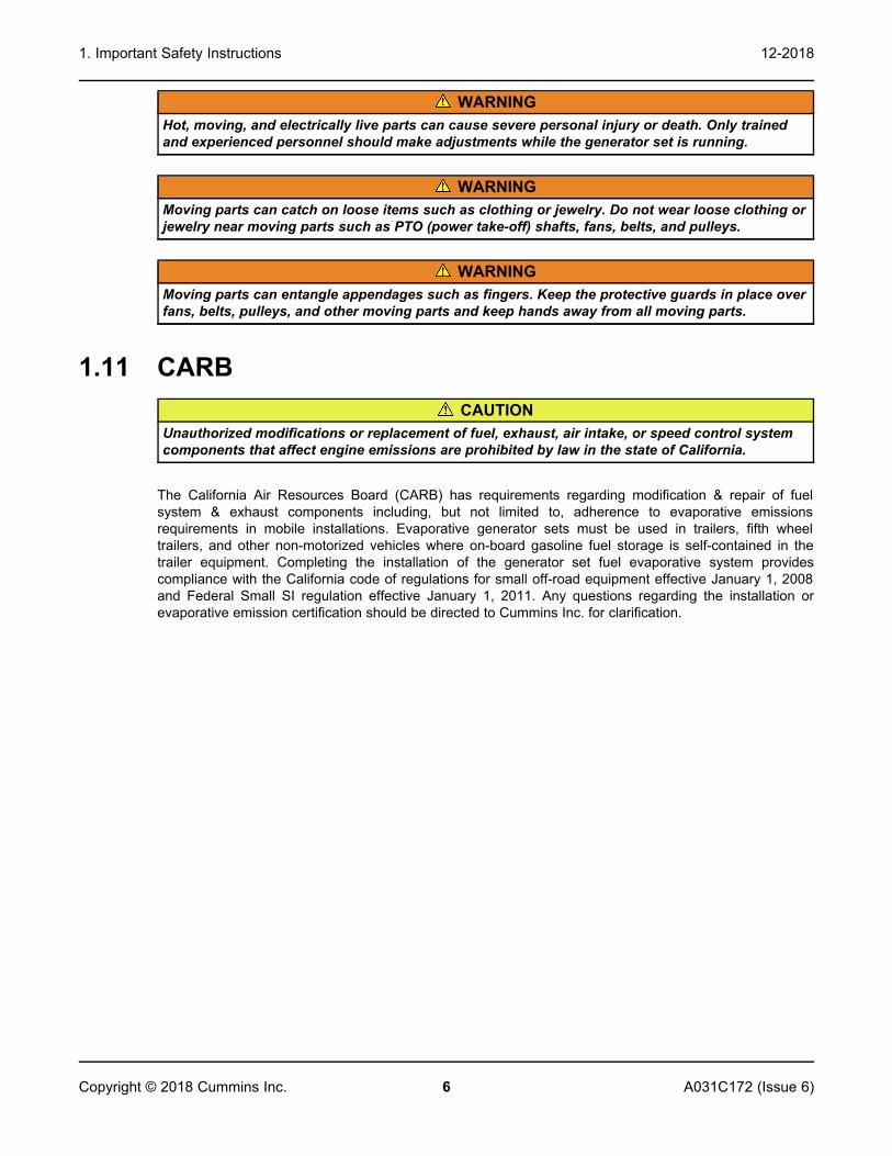
WARNINGHot, moving, and electrically live parts can cause severe personal injury or death. Only trainedand experienced personnel should make adjustments while the generator set is running.
WARNINGMoving parts can catch on loose items such as clothing or jewelry. Do not wear loose clothing orjewelry near moving parts such as PTO (power take-off) shafts, fans, belts, and pulleys.
WARNINGMoving parts can entangle appendages such as fingers. Keep the protective guards in place overfans, belts, pulleys, and other moving parts and keep hands away from all moving parts.
1.11 CARBCAUTION
Unauthorized modifications or replacement of fuel, exhaust, air intake, or speed control systemcomponents that affect engine emissions are prohibited by law in the state of California.
The California Air Resources Board (CARB) has requirements regarding modification & repair of fuelsystem & exhaust components including, but not limited to, adherence to evaporative emissionsrequirements in mobile installations. Evaporative generator sets must be used in trailers, fifth wheeltrailers, and other non-motorized vehicles where on-board gasoline fuel storage is self-contained in thetrailer equipment. Completing the installation of the generator set fuel evaporative system providescompliance with the California code of regulations for small off-road equipment effective January 1, 2008and Federal Small SI regulation effective January 1, 2011. Any questions regarding the installation orevaporative emission certification should be directed to Cummins Inc. for clarification.

7A031C172 (Issue 6) Copyright © 2018 Cummins Inc.
2 Introduction
2.1 About This ManualThis manual is a guide for the installation of the generator sets listed on the front cover. Proper installationis essential for top performance. Read through this manual before starting the installation. Leave thismanual in the vehicle.
The installer must be qualified to perform installation of electrical and mechanical equipment.
This manual addresses the following aspects of the installation:
• Location, Mounting, and Ventilation
• Exhaust Connections
• Fuel Connections
• Electrical Connections
• Startup
See the Operator Manual for operation and maintenance and the Service Manual for service.
The information contained within the manual is based on information available at the time of printing. Inline with Cummins Inc. policy of continuous development and improvement, information may change atany time without notice. The users should therefore make sure that before commencing any work, theyhave the latest information available. The latest version of this manual is available on QuickServe Online(https://quickserve.cummins.com).
2.2 Related LiteratureBefore any attempt is made to operate the generator set, the operator should take time to read all of themanuals supplied with the generator set, and to familiarize themselves with the warnings and operatingprocedures.
CAUTIONA generator set must be operated and maintained properly if you are to expect safe and reliableoperation. The Operator manual includes a maintenance schedule and a troubleshooting guide.The Health and Safety manual must be read in conjunction with this manual for the safeoperation of the generator set:
• Health and Safety Manual (0908-0110)
The relevant manuals appropriate to your generator set are also available, the documents below are inEnglish:
• Operator Manual for RV Generator Set HGJBB (Spec A-B) (A031C171)
• Installation Manual for RV Generator Set HGJBB (Spec A-B) (A031C172)
• Generator Set Service Manual for RV Generator Set HGJBB (Spec A) (A031C173)
• Recommended Spares List (RSL) for RV Generator Set HGJBB (Spec A) (A043W890)
• Parts Manual for RV Generator Set HGJBB (Spec A-B) (A035B506)
• Standard Repair Times - CY Family (A031C174)

2. Introduction 12-2018
8 A031C172 (Issue 6)Copyright © 2018 Cummins Inc.
• Service Tool Manual (A043D529)
• Failure Code Manual (F1115C)
• Warranty Administration Manual (4021290)
• Global Commercial Warranty Statement (A028U870)
2.3 Installation Codes and Standards for SafetyCAUTION
The Commercial Generator Set Warranty applies only when the generator set is installed in acommercial or recreational vehicle. The RV Generator Set Warranty applies only when thegenerator set is installed in a recreational vehicle.
The installer bears sole responsibility for the selection of the appropriate generator set, for its properinstallation, and for obtaining approvals from the authorities (if any) having jurisdiction over the installation.The generator sets meet the basic requirements of the Standard for Safety for Engine Generator Sets forRecreational Vehicles, ANSI/RVIA EGS-1 and are suitable for installation in accordance with:
• ANSI A1192 (NFPA No. 501C)—Recreational Vehicles
• NFPA No. 70, Article 551—Recreational Vehicles and RV Parks
• CSA Electrical Bulletin 946—Requirements for Internal Combustion Engine-Driven ElectricGenerators for Use in Recreational Vehicles
Federal, state, and local codes, such as the California Administrative Code—Title 25 (RV installation),might also be applicable. Installation codes and recommendations can change from time-to-time and aredifferent in different countries, states, and municipalities. Obtain the standards listed in the table below forreference.
TABLE 1. REFERENCE CODES AND STANDARDS
Code of FederalRegulations, Title 49:
Chapter III andChapter V
Superintendent of DocumentsP. O. Box 371954
Pittsburgh, PA 15250-7954
NFPA 58, 70, 1192National Fire Protection Association
470 Atlantic AvenueBoston, MA 02210
ANSI/RVIA-EGS-1Recreational Vehicle Industry Association
14650 Lee RoadChantily, VA 22021
CaliforniaAdministrative
Code—Title 25,Chapter 3
State of California Documents SectionP.O. Box 1015
North Highlands, CA 95660
CAN/CSA-Z240Recreational Vehicles
Bulletin 946
Canadian Standards Association Housing and Construction Materials Section178 Rexdale Blvd.
Rexdale, Ontario, Canada M9W 1R3

2. Introduction12-2018
9A031C172 (Issue 6) Copyright © 2018 Cummins Inc.
SAE J1231, J1508,J2044, J2599
SAE World Headquarters400 Commonwealth Drive
Warrendale, PA 15096
2.4 Electromagnetic Compatibility ComplianceGenerator sets emit and receive electromagnetic (radio frequency) energy. If the generator set affectsoperation of nearby devices, or nearby devices affect generator set operation, increase the distancebetween them.
When used in countries where compliance to the EMC directive is required: This generator set has beenevaluated for use in the residential, commercial, and light industrial environments.
2.5 Specifications2.5.1 Gasoline Model Specifications
TABLE 2. GASOLINE MODEL SPECIFICATIONS
2.8 HGJBB 2.3 HGJBB 2.8 HGJBB
GENERATOR: 2-Pole Revolving Field, Self-Excited, 1-Phase, Electronically Regulated, Direct Drive
Power 2800 Watts 2300 Watts 2800 Watts
Frequency1 60 Hz 50 Hz 60 Hz
Voltage 120 Volts 230 Volts 100 Volts
Current 23.3 Amps 10 Amps 28 Amps
Breaker 25 Amps 10 Amps 30 Amps
Speed 3600 RPM 3000 RPM 3600 RPM
FUEL CONSUMPTION:
No Load 0.78 l/h (0.2 gph) 0.69 l/h (0.18 gph) 0.78 l/h (0.2 gph)
Half Load 1.32 l/h (0.35 gph) 1.18 l/h (0.31 gph) 1.32 l/h (0.35 gph)
Fuel Load 1.75 l/h (0.46 gph) 1.56 l/h (0.41 gph) 1.75 l/h (0.46 gph)
ENGINE: 1-Cylinder, 4-Cyle, Spark Ignited, OHC, Air-Cooled
Bore 67 mm (2.64 in)
Stroke 60 mm (2.36 in)
Displacement 211 cm3 (12.87 in3)
Compression Ratio 8.5 : 1
Oil Capacity 0.6 liters (0.63 qt)
Intake Valve Lash(Cold) 0.12-0.15 mm (0.0047-0.0059 in)
Exhaust Valve Lash(Cold) 0.12-0.15 mm (0.0047-0.0059 in)

2. Introduction 12-2018
10 A031C172 (Issue 6)Copyright © 2018 Cummins Inc.
2.8 HGJBB 2.3 HGJBB 2.8 HGJBB
Spark Plug Gap 0.6–0.7 mm (0.024-0.028 in)
Ignition Timing 23° BTDC, non-adjustable
Ignition Coil Gap 0.3–0.7 mm (0.012-0.020 in)
Compression 3.9 kgf/cm2 (55.47 lbf/in2) @ 500 RPM
DC SYSTEM:
Battery Voltage 12 Volts
Minimum BatteryRating 360 CCA @ –18 °C (0 °F)
INSTALLATION:
Minimum Free Air InletArea 232 cm2 (36 in2)
Weight 57 kg (125 lbs)
Minimum CompartmentSize (H x D x W)2 325 mm x 415 mm x 560 mm (12.8 in x 16.3 in x 22.0 in)
1. 60 Hz models are listed by CSA and the US Testing Company.2. See the Installation Manual for additional considerations when sizing the generator set compartment.
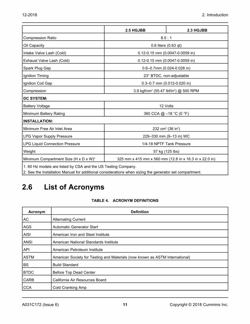
2.5.2 LPG Model SpecificationsTABLE 3. LPG MODEL SPECIFICATIONS
2.5 HGJBB 2.3 HGJBB
GENERATOR: 2-Pole Revolving Field, Self-Excited, 1-Phase, Electronically Regulated, Direct Drive
Power 2500 Watts 2300 Watts
Frequency1 60 Hz 50 Hz
Voltage 120 Volts 230 Volts
Current 20.8 Amps 10 Amps
Breaker 21 Amps 10 Amps
Speed 3600 RPM 3000 RPM
FUEL CONSUMPTION:
No Load 0.53 kg/h (1.17 lbs/h) 0.49 kg/h (1.08 lbs/h)
Half Load 0.76 kg/h (1.66 lbs/h) 0.69 kg/h (1.53 lbs/h)
Full Load 1.02 kg/h (2.25 lbs/h) 0.94 kg/h (2.07 lbs/h)
ENGINE: 1-Cylinder, 4-Cycle, Spark Ignited, OHC, Air-Cooled
Bore 67 mm (2.64 in)
Stroke 60 mm (2.36 in)
Displacement 211 cm3 (12.87 in3)
2. Introduction12-2018
11A031C172 (Issue 6) Copyright © 2018 Cummins Inc.
2.5 HGJBB 2.3 HGJBB
Compression Ratio 8.5 : 1
Oil Capacity 0.6 liters (0.63 qt)
Intake Valve Lash (Cold) 0.12-0.15 mm (0.0047-0.0059 in)
Exhaust Valve Lash (Cold) 0.12-0.15 mm (0.0047-0.0059 in)
Spark Plug Gap 0.6–0.7mm (0.024-0.028 in)
Ignition Timing 23° BTDC, non-adjustable
Ignition Coil Gap 0.3–0.7 mm (0.012-0.020 in)
Compression 3.9 kgf/cm2 (55.47 lbf/in2) @ 500 RPM
DC SYSTEM:
Battery Voltage 12 Volts
Minimum Battery Rating 360 CCA @ –18 °C (0 °F)
INSTALLATION:
Minimum Free Air Inlet Area 232 cm2 (36 in2)
LPG Vapor Supply Pressure 229–330 mm (9–13 in) WC
LPG Liquid Connection Pressure 1/4-18 NPTF Tank Pressure
Weight 57 kg (125 lbs)
Minimum Compartment Size (H x D x W)2 325 mm x 415 mm x 560 mm (12.8 in x 16.3 in x 22.0 in)
1. 60 Hz models are listed by CSA and the US Testing Company.2. See the Installation Manual for additional considerations when sizing the generator set compartment.
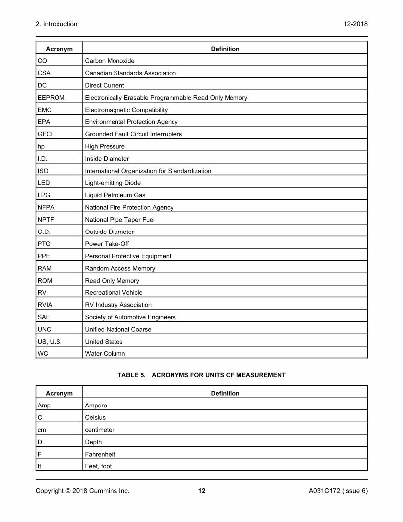
2.6 List of AcronymsTABLE 4. ACRONYM DEFINITIONS
Acronym Definition
AC Alternating Current
AGS Automatic Generator Start
AISI American Iron and Steel Institute
ANSI American National Standards Institute
API American Petroleum Institute
ASTM American Society for Testing and Materials (now known as ASTM International)
BS Build Standard
BTDC Before Top Dead Center
CARB California Air Resources Board
CCA Cold Cranking Amp
2. Introduction 12-2018
12 A031C172 (Issue 6)Copyright © 2018 Cummins Inc.
Acronym Definition
CO Carbon Monoxide
CSA Canadian Standards Association
DC Direct Current
EEPROM Electronically Erasable Programmable Read Only Memory
EMC Electromagnetic Compatibility
EPA Environmental Protection Agency
GFCI Grounded Fault Circuit Interrupters
hp High Pressure
I.D. Inside Diameter
ISO International Organization for Standardization
LED Light-emitting Diode
LPG Liquid Petroleum Gas
NFPA National Fire Protection Agency
NPTF National Pipe Taper Fuel
O.D. Outside Diameter
PTO Power Take-Off
PPE Personal Protective Equipment
RAM Random Access Memory
ROM Read Only Memory
RV Recreational Vehicle
RVIA RV Industry Association
SAE Society of Automotive Engineers
UNC Unified National Coarse
US, U.S. United States
WC Water Column
TABLE 5. ACRONYMS FOR UNITS OF MEASUREMENT
Acronym Definition
Amp Ampere
C Celsius
cm centimeter
D Depth
F Fahrenheit
ft Feet, foot

2. Introduction12-2018
13A031C172 (Issue 6) Copyright © 2018 Cummins Inc.
Acronym Definition
ft-lbs Foot-pounds
gph Gallons per hour
H Height
Hz Hertz
in Inch
kg kilogram
kg/h kilograms per hour
kgf/cm2 kilogram-force per square centimeter
kW kilowatt
l/h Liters per hour
lb Pound
lbf/in2 OR psi Pound per square inch
lbs/h Pounds per hour
m Meter
mm millimeter
Nm Newton meter
psi OR lbf/in2 Pound per square inch
qt Quart
RPM Revolutions per Minute
VAC Volts Alternating Current
VDC Volts Direct Current
W Watts, Width

This page is intentionally blank.
2. Introduction 12-2018
14 A031C172 (Issue 6)Copyright © 2018 Cummins Inc.
15A031C172 (Issue 6) Copyright © 2018 Cummins Inc.
3 Location, Mounting, and VentilationThe location, mounting, and ventilation of a generator set must be such that mounting is secure, engineexhaust and fuel vapors are prevented from entering the vehicle, rain and road debris are prevented fromentering the generator set, and ready access is afforded for operating the generator set and performingperiodic maintenance.
3.1 LocationTypical locations for generator set installation are shown below.
The location must provide:
• Ready access for starting and stopping the generator set and performing all periodic maintenance.
• Separation from sources of flammable vapors, such as batteries and fuel tanks, which the generatorset could ignite.
• Access for connecting and disconnecting fuel lines, battery cables, remote control wiring, and ACwiring.
• Access from below for draining engine oil and changing the oil filter.
• Unobstructed space below the generator set for proper cooling air flow.
• The generator set must not share a compartment or ventilation with batteries or fuel tanks. Anoperating generator set can ignite flammable vapors.
• Make sure the space below the generator set cooling outlet is unobstructed for at least 305 mm (12in) and open on at least 3 sides.
• Locate or shield the generator set cooling air openings from direct rain, road splash and debristhrown up by the road wheels.
• Space to mount the generator set with at least 12.7 mm (1/2 in) clearance at the top and any side ofthe generator set. Minimum clearances apply to any thermal or acoustic insulation with which acompartment may be lined.
• Locating a generator set more than 5 feet above the floor and at the very back of the vehicle canresult in 'g' forces imparted to the generator set that causes physical damage to it as it travels downthe road. Generator sets located in these areas do not have warranty coverage for damageresulting from high 'g' loads.
• Locating the generator set near the front of the coach or vehicle (directly behind or under the driveror passenger seat) creates a situation where heat from the running propulsion engine can be drawninto the generator set while stationary or moving. An alternate location should be selected for thegenerator set.
NOTICEConsider air flow requirements for passenger side installations when the generator is required tooperate while the vehicle is in motion. Installations must meet rise over ambient tests (see HotAir Recirculation Test) in various modes of operation.

3. Location, Mounting, and Ventilation 12-2018
16 A031C172 (Issue 6)Copyright © 2018 Cummins Inc.
3.1.1 Typical Generator Set Locations - Class A RV
FIGURE 1. TYPICAL GENERATOR SET LOCATIONS - CLASS A RV
3.1.2 Typical Generator Set Locations - Class C RV
FIGURE 2. TYPICAL GENERATOR SET LOCATIONS - CLASS C RV

3. Location, Mounting, and Ventilation12-2018
17A031C172 (Issue 6) Copyright © 2018 Cummins Inc.
3.1.3 Typical Generator Set Locations - Class B Van
FIGURE 3. TYPICAL GENERATOR SET LOCATIONS - CLASS B VAN
3.1.4 Typical Generator Set Locations - Pickup Truck Camper
FIGURE 4. TYPICAL GENERATOR SET LOCATIONS - PICKUP TRUCK CAMPER
3.2 MountingWARNING
The generator set support structure must be designed and installed to support and restrain thedynamic weight of the generator set. Failure to do so can result in the generator set droppingonto the roadway causing property damage, severe personal injury, or death.
3. Location, Mounting, and Ventilation 12-2018
18 A031C172 (Issue 6)Copyright © 2018 Cummins Inc.
NOTICEAfter May 1, 2015, Cummins will not support new mobile roof top mounted RV/CM generatorapplications. For reasons explained & demonstrated in application engineering bulletin AEB 104-022012, this location is an application that Cummins does not recommend or support.Normal warranty applies.
• Support the generator set on a structure able to resist the dynamic weight of the generator set: ± 3g-force vertical and ± 1 g-force horizontal. See Section 2.5 on page 9 for the weight of thegenerator set. See the outline drawings in Appendix B on page 49 for mounting bolt hole locations.
TABLE 6. MOUNTING SCREWS
Quantity Type Torque
3 or 4 (depending on mountingmethod)
3/8-16 NC bolts 47 Nm
3.2.1 Below Floor MountingMounting kits are available for below floor mounting. Follow the instructions in the kit.
Do not mount the generator set within the approach or departure angles of the vehicle or below the axleline.
3.2.2 Insulating MaterialsAcoustic/thermal insulation and adhesive must be classified as "Self-Extinguishing" at not less than 90 oC(200 oF). Do not line the bottom of a compartment with insulation since it absorbs fuel and oil.
3.2.3 Fire and Exhaust BarriersWARNING
Exhaust gas and fire are deadly! Install a vapor-tight and fire-resistant barrier of approvedmaterials between the generator set and the vehicle interior. Do not duct generator set coolingair into the vehicle for heating.
• Barriers to provide vapor and fire resistance must be installed between the generator set and theinterior of the vehicle if the generator set is mounted below the floor.
• If the generator set is mounted in a compartment on the floor of the vehicle, the entire compartmentmust be lined with vapor and fire resistive materials.
• Use approved materials (26 gauge galvanized steel or equivalent). See NFPA 1192 for details. Referto local codes and standards for additional information.
• All seams and openings in the barriers for wiring, mounting screws, etc. must be sealed.
3. Location, Mounting, and Ventilation12-2018
19A031C172 (Issue 6) Copyright © 2018 Cummins Inc.
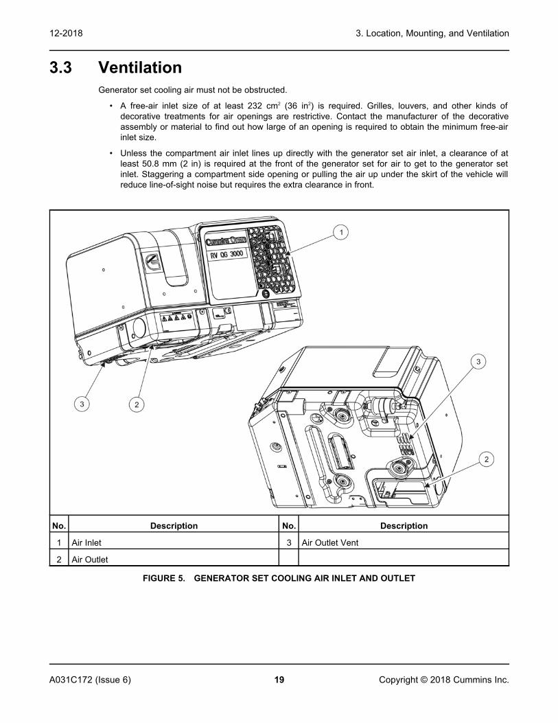
3.3 VentilationGenerator set cooling air must not be obstructed.
• A free-air inlet size of at least 232 cm2 (36 in2) is required. Grilles, louvers, and other kinds ofdecorative treatments for air openings are restrictive. Contact the manufacturer of the decorativeassembly or material to find out how large of an opening is required to obtain the minimum free-airinlet size.
• Unless the compartment air inlet lines up directly with the generator set air inlet, a clearance of atleast 50.8 mm (2 in) is required at the front of the generator set for air to get to the generator setinlet. Staggering a compartment side opening or pulling the air up under the skirt of the vehicle willreduce line-of-sight noise but requires the extra clearance in front.
No. Description No. Description
1 Air Inlet 3 Air Outlet Vent
2 Air Outlet
FIGURE 5. GENERATOR SET COOLING AIR INLET AND OUTLET

This page is intentionally blank.
3. Location, Mounting, and Ventilation 12-2018
20 A031C172 (Issue 6)Copyright © 2018 Cummins Inc.

21A031C172 (Issue 6) Copyright © 2018 Cummins Inc.
4 Exhaust ConnectionsWARNING
This product incorporates a catalyst exhaust system which leads to higher exhaust gastemperatures. The installer must review and follow all guidelines for the installation. Care mustbe taken to make sure that all installation requirements in this entire manual are met.
The generator set is equipped with a U.S. Forest Service approved spark-arrest muffler. Failure to provideand maintain a spark arrester can be a violation of the law. Liability for damage, injury, and warrantyexpense due to the modification of the exhaust system or the use of unapproved parts is the responsibilityof the person performing the modification or installing the unapproved exhaust system parts.
WARNINGEXHAUST GAS IS DEADLY! To keep exhaust gases from entering the vehicle do not terminatethe exhaust tailpipe underneath the vehicle or closer than 153 mm (6 in) to openings into thevehicle or route it such that it is not protected. Use approved materials only.The tailpipe of the generator set will be hot during operation and can cause severe burns. Toreduce the risk of contact, concentration must be used where the tailpipe will be located androuted.
The generator set exhaust system must be gas tight and designed to prevent entry of exhaust gasses intothe vehicle interior.
4.1 Tailpipe InstallationThe muffler is mounted inside the generator set and has a flange to which the tailpipe adapter (availablefrom Cummins) is bolted or a collar to which the tailpipe is clamped or a short adapter bolted to its outletflange.
WARNINGFlexible pipe is not gas tight or durable and can cause exhaust gas leaks. Do not use flexiblepipe for tailpipe.
1. Use 18-gauge 1-1/8 inch I.D. aluminized steel tubing or material of equivalent heat and corrosionresistance for the tailpipe.
2. Support a tailpipe longer than 457 mm (1-1/2 ft) near its end and at intervals of 900 mm (3 ft) or less.Use automotive-type tailpipe hangers. Do not attach the hangers to combustible material such aswood.
3. Use U-bolt muffler clamps to connect sections of tailpipe. Overlapping pipe should be slotted.
4. Do not route the tailpipe near fuel lines or fuel tanks.
5. Do not route the tailpipe closer than 76 mm (3 in) to combustible material (wood, felt, cotton, organicfibers, etc.) unless it is insulated or shielded. The temperature rise (above ambient) on adjacentcombustible material must not exceed 65 °C (117 °F).
6. Do not route the exhaust tailpipe underneath the oil drain.
7. Do not route the exhaust tailpipe such that is will restrict the air inlet/outlet.

4. Exhaust Connections 12-2018
22 A031C172 (Issue 6)Copyright © 2018 Cummins Inc.
8. To keep the tailpipe from being damaged, do not route it such that it protrudes into the approach ordeparture angles of the vehicle or below the axle clearance line.
9. Do not interconnect generator set and vehicle engine exhaust systems.
10. Do not terminate the tailpipe underneath the vehicle. Extend it a minimum of 25 mm (1 in) beyondthe perimeter of the vehicle. Support the end of the tailpipe such that it cannot be pushed in and upunder the skirt of the vehicle.
11. Do not terminate the tailpipe such that it is closer than 153 mm (6 in) to any opening, such as a door,window, vent, or unsealed compartment into the vehicle interior.
CAUTIONExcessive back pressure can cause loss of performance and engine damage.
12. Make sure a tailpipe deflector will not cause excessive back pressure.
FIGURE 6. TYPICAL TAILPIPE INSTALLATION (BOTTOM OF UNIT)
FIGURE 7. TYPICAL TAILPIPE INSTALLATION (SIDE OF UNIT)

4. Exhaust Connections12-2018
23A031C172 (Issue 6) Copyright © 2018 Cummins Inc.
FIGURE 8. EXHAUST TAILPIPE CONNECTIONS
No. Description No. Description
1 Tailpipe 2 153 mm (6 in)
No opening into the vehicle interior may be closer than 153 mm (6 in) to the end of the tail pipe (within area 2,identified in this image).
FIGURE 9. MINIMUM DISTANCES TO OPENINGS

4. Exhaust Connections 12-2018
24 A031C172 (Issue 6)Copyright © 2018 Cummins Inc.
No. Description No. Description
A Side view 1 25 mm (1 inch)
B Straight-on view 2 The last tailpipe hanger must be as close to the endas possible.
FIGURE 10. TERMINATING THE EXHAUST TAILPIPE
4.2 Vehicle Clearances - Class A RV
No. Description No. Description
1 Approach Angle 3 Departure Angle
2 Axle Clearance Line
FIGURE 11. VEHICLE CLEARANCES - CLASS A RV

4. Exhaust Connections12-2018
25A031C172 (Issue 6) Copyright © 2018 Cummins Inc.
4.3 Vehicle Clearances - Class B Van
No. Description No. Description
1 Approach Angle 3 Departure Angle
2 Axle Clearance Line
FIGURE 12. VEHICLE CLEARANCES - CLASS B VAN
4.4 Vehicle Clearances - Pickup Truck Camper
No. Description No. Description
1 Approach Angle 3 Departure Angle
2 Axle Clearance Line
FIGURE 13. VEHICLE CLEARANCES - PICKUP TRUCK CAMPER

This page is intentionally blank.
4. Exhaust Connections 12-2018
26 A031C172 (Issue 6)Copyright © 2018 Cummins Inc.

27A031C172 (Issue 6) Copyright © 2018 Cummins Inc.
5 Fuel ConnectionsSee the Operator Manual for recommended fuels and Section 2.5 on page 9 for fuel consumption.
CAUTIONUnauthorized modifications or replacement of fuel, exhaust, air intake, or speed control systemcomponents that affect engine emissions are prohibited by law in California.
5.1 Gasoline MotorizedThe maximum fuel pump lift is 914 mm (36 in).
The generator set and propulsion engine fuel supply and return lines must not be interconnected.
Connections meet the requirements of the following SAE standards, when applicable:
• J1231 (Formed Tube Ends for Hose Connections and Hose Fittings)
• J1508 (Hose Clamp Specifications)
• J2260 (Nonmetallic Fuel System Tubing with One or More Layers)
• J2044 (Quick Connector Specification for Liquid Fuel and Vapor/Emissions Systems)
Terminate the generator set fuel pickup above the vehicle engine pickup in the supply tank to keep thegenerator set from running the vehicle out of fuel.
Connect 1/4 inch fuel line from the vehicle fuel tank to the generator set.
5. Fuel Connections 12-2018
28 A031C172 (Issue 6)Copyright © 2018 Cummins Inc.
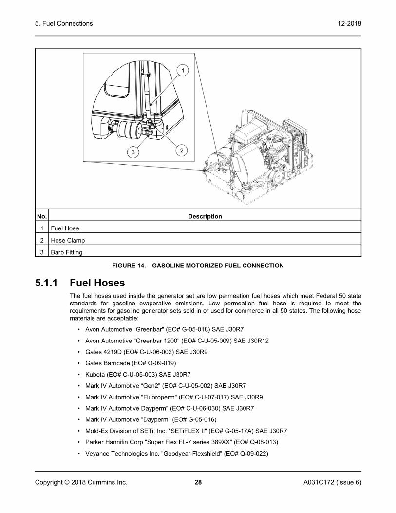
No. Description
1 Fuel Hose
2 Hose Clamp
3 Barb Fitting
FIGURE 14. GASOLINE MOTORIZED FUEL CONNECTION
5.1.1 Fuel HosesThe fuel hoses used inside the generator set are low permeation fuel hoses which meet Federal 50 statestandards for gasoline evaporative emissions. Low permeation fuel hose is required to meet therequirements for gasoline generator sets sold in or used for commerce in all 50 states. The following hosematerials are acceptable:
• Avon Automotive “Greenbar" (EO# G-05-018) SAE J30R7
• Avon Automotive “Greenbar 1200" (EO# C-U-05-009) SAE J30R12
• Gates 4219D (EO# C-U-06-002) SAE J30R9
• Gates Barricade (EO# Q-09-019)
• Kubota (EO# C-U-05-003) SAE J30R7
• Mark IV Automotive “Gen2" (EO# C-U-05-002) SAE J30R7
• Mark IV Automotive "Fluoroperm" (EO# C-U-07-017) SAE J30R9
• Mark IV Automotive Dayperm" (EO# C-U-06-030) SAE J30R7
• Mark IV Automotive "Dayperm" (EO# G-05-016)
• Mold-Ex Division of SETi, Inc. "SETiFLEX II" (EO# G-05-17A) SAE J30R7
• Parker Hannifin Corp "Super Flex FL-7 series 389XX" (EO# Q-08-013)
• Veyance Technologies Inc. "Goodyear Flexshield" (EO# Q-09-022)

5. Fuel Connections12-2018
29A031C172 (Issue 6) Copyright © 2018 Cummins Inc.
CAUTIONLubricants used when connecting fuel hoses can leave residues that can clog fuel jets. Only usesoap-free lubricants such as WD40 which runs through with the fuel without leaving residuesthat can clog fuel jets.
5.1.2 Fuel LinesTubing:
• Use 1/4 inch I.D. (± 0.003 inch) welded and drawn Type 304L stainless or AISI 1008-1010 lowcarbon steel tubing of 0.028 inch minimum wall thickness.
• Tubing must meet requirements for 150 psi operating pressure (Ref. ASTM A 539-99) and havecorrosion resistance equal to or better than hot-dipped zinc galvanized.
Hose Beads:
• Use suitable tooling to form tubing ends into SAE J1231 Type 1 or Type 3 double-flare hose beads.
• Recommended for all tubing and fittings.
Flexible Hose: Use 1/4 inch I.D. fuel hose that meets applicable standards for evaporative emissions.
5.1.3 Routing Fuel LinesWARNING
Electric arcs can ignite gasoline leading to severe personal injury or death. Do not run wiring andfuel lines together.
1. Route the fuel line along bulkheads and frame members such that it is protected. The entire length ofthe fuel line must be visible for inspection and accessible for replacement.
It is preferred that fuel line routing be parallel to the motorized chassis fuel line.
FIGURE 15. FUEL LINE PREFERRED ROUTING
NOTICEThe fuel line should be at or above the top of the fuel tank to reduce siphoning if a linebreaks or a hose comes off.
2. Support and protect fuel lines to restrain movement and prevent chaffing or contact with sharpedges, electrical wiring, and hot exhaust parts.

5. Fuel Connections 12-2018
30 A031C172 (Issue 6)Copyright © 2018 Cummins Inc.
5.2 LPGWARNING
LPG is flammable and explosive and can cause asphyxiation. NFPA 58, Section 1.6 requires allpersons handling LPG to be trained in proper handling and operating procedures.
WARNINGHigh LPG supply pressure can cause gas leaks which can lead to fire and severe personal injuryor death. LPG supply pressure must be adjusted to Specifications by trained and experiencedpersonnel.
WARNINGSparks can ignite LPG, leading to severe personal injury or death. Do not run electrical wiringand fuel lines together. Separate them with conduit or tubing if run through the same opening.Do not tie them together.
WARNINGLPG leaks from the vent hose can lead to explosive accumulations inside the generator setcompartment. Route the LPG vent hose so that it vents to the outside or provide requiredopenings.
WARNINGThe flameout of an unvented LPG appliance can lead to explosive accumulations of gas insidethe vehicle and the danger of severe personal injury or death. Do not connect the generator setfuel supply line to any vehicle appliance supply line.
WARNINGTesting for gas leaks with a flame can cause a fire or explosion that could lead to severepersonal injury or death. use approved methods only.
NFPA 58, the Standard for the Storage and Handling of Liquefied Petroleum Gases (NFPA 58) should beused as a guide for the installation of the LPG fuel system.
NFPA 1192, the Standard on Recreation Vehicles for Liquefied Petroleum Gases should be used as aguide for the installation of the LPG fuel system in regard to the following sections:
• Propane Container
• Propane Supply Connection/Connector
• Regulated High Pressure Piping
• Propane Systems
• Propane Piping Systems
• Propane Piping Design
• Propane Pipe Sizing
NOTICEGenerator is included in pipe sizing calculations and testing.

5. Fuel Connections12-2018
31A031C172 (Issue 6) Copyright © 2018 Cummins Inc.
• Special Requirement for High Pressure Testing
• Testing Low-Pressure Piping Systems for Propane Leakage After Appliances are Connected
NOTICEGenerator is considered connected as an appliance for testing.
• Testing Regulated High-Pressure Piping System for Gas Leakage
Connect LPG fuel system:
1. Adjust the gas supply pressure (at the gas inlet of the pressure regulator) to at least 229 mm (9 in)Water Column (WC). The pressure must not exceed 330 mm (13 in) WC.
2. Route LPG fuel lines away from electrical wiring and hot engine exhaust components. Fuel linesshould be accessible for inspection and replacement, protected from damage, and secured toprevent kinking, contact with sharp edges, and chafing due to vibration.
3. Route the LPG vent hose so that it vents to the outside or provide required openings.
4. For a long fuel line run, use seamless steel tubing with flared ends. Make flexible hose connectionsat the fuel tank and at the generator set. Use 3/8 inch I.D. fuel line for runs up to 0.9 m (3 ft) and 1/2inch I.D. up to 4.6 m (15 ft).
Do not connect the generator set fuel supply line to any appliance fuel supply line. The generator set candraw fuel away from other appliances and cause a flame out. To prevent the possibility of flameout, thefuel supply system must be designed to deliver sufficient fuel for normal operation of the generator set andother appliances at the expected temperature conditions. It may be necessary to use a separate fuel tankfor the generator set if sufficient fuel cannot be supplied with a single tank system.
No. Description No. Description
1 LPG Fuel Tank 5 Stove
2 Regulator 6 Heating
3 Main Fuel Line 7 Refrigerator
4 Generator Set
FIGURE 16. LPG FUEL LINE APPLIANCE CONNECTIONS (2.5 THROUGH 5.5 KW LPG SYSTEMS)
LPG systems with 6.5 kW must have dedicated:
• Tank
• Regulator
• Piping/Connections
Upon completion of the installation, fill the LPG tank and test every joint and fitting in the LPG supplysystem using an approved method, such as soap bubbles.

5. Fuel Connections 12-2018
32 A031C172 (Issue 6)Copyright © 2018 Cummins Inc.
Because variations in fuel, altitude, and ambient temperature affect performance, it might be necessary tomake governor and fuel mixture adjustments once the generator set has been installed. See the ServiceManual.
No. Description No. Description
1 Vapor Shutoff Valve 5 Demand Regulator
2 Two Stage Regulator 6 Fuel Shutoff Solenoid
3 11 inches W.C. Outlet Pressure 7 Fuel Line Size: 3/8 inch I.D. up to 0.9 m (3 ft) or 1/2inch I.D. up to 4.6 m (15 ft)
4 LPG Carburetor
FIGURE 17. TYPICAL LPG VAPOR WITHDRAWAL FUEL SYSTEM

33A031C172 (Issue 6) Copyright © 2018 Cummins Inc.
6 Electrical ConnectionsWARNING
HAZARDOUS VOLTAGE! Touching uninsulated live parts inside the generator set and connectedequipment can result in severe personal injury or death. For your protection, stand on a drywooden platform or rubber insulating mat, make sure your clothing and shoes are dry, removejewelry from your hands, and use tools with insulated handles. Secure protective covers whencompleting installation.
WARNINGIMPROPER WIRING can cause fire or electric shock resulting in severe personal injury or death.
WARNINGAccidental starting of the generator set can cause severe personal injury or death. Do notconnect the starting battery until instructed in Chapter 7 on page 41.
6.1 AC Power Output ConnectionsThe generator set is equipped with a circuit breaker and 3.1 m (124 in) long 25-A (12 AWG) leads for ACpower output which exit through a rain-tight 1/2 inch trade size conduit connector.
The leads can be terminated at the main AC distribution panel where individual breakers can be providedfor vehicle/trailer AC loads.
If longer AC cable is required or code stipulates, a 4 x 4 inch junction box is mounted near the generatorset. Use a weather type junction box if it is exposed to the elements. When extending this cable, use theproper size wire for amperage and insulation temperature rated wire (typically 12 AWG) to the main ACdistribution panel.
FIGURE 18. AC OUTPUT CONDUIT

6. Electrical Connections 12-2018
34 A031C172 (Issue 6)Copyright © 2018 Cummins Inc.
6.1.1 Wiring MethodsFollow the National Electrical Code, especially noting the following:
1. Have a qualified electrician supervise and inspect the installation of all AC wiring.
2. Install vibration-proof switches and controls that won't open and close circuits when the vehicle is inmotion.
3. Provide ground fault circuit interrupters (GFCIs) for all convenience power receptacles.
4. Route AC wiring, remote control wiring, and fuel lines separately.
5. Seal all conduit openings into the vehicle interior to keep out exhaust gas. Apply silicone rubber oran equivalent type of sealant inside and outside each conduit connector. (Flexible conduit is notvapor tight and will allow exhaust gas to enter along the wires if not sealed.)
WARNINGFaulty grounding can lead to fire and electrocution, resulting in severe personal injury ordeath. Grounding must be in accordance with applicable codes.
6. Bond the generator set and all connected AC and DC equipment and controls to a commongrounding point in accordance with applicable codes.
6.1.2 Connecting to Shore PowerWARNING
ElectrocutionIncorrect connection of the generator set and shore power can cause severe personal injury andequipment damage.Use an approved switching device to prevent interconnections.
A vehicle with provisions for connecting to utility power must have an approved device to keep thegenerator set and utility from being interconnected.

6. Electrical Connections12-2018
35A031C172 (Issue 6) Copyright © 2018 Cummins Inc.
No. Description No. Description
1 Generator Set 5 To Vehicle AC Distribution Panel
2 Green 6 Utility Power
3 White 7 Transfer Switch
4 Black
FIGURE 19. TYPICAL CONNECTIONS WITH TRANSFER SWITCH AND UTILITY
6.2 Remote Control ConnectionsThe generator set has an 8-pin connector for remote control connections. Wiring harnesses in severallengths are available separately for connections between the generator set and remove control panel.
To make connections to a remote control panel:
1. Push the generator set remote control connector through the entrance hole in the side of thegenerator set housing and snap it together with the remote wiring harness connector male.
2. Refer to the following table to fabricate the remote control panel and/or wiring harness when notusing the accessories available from Cummins. Mark the remote control end of each lead to identifythe connector pin number at the generator set.
Use insulated 18 AWG copper conductors for distances up to 9 m (30 ft) and heavier gaugeconductors for greater distances. Protect the wiring with full-length flexible sheathing.
3. Route control leads separately from AC power leads to reduce the possibility of erratic operation dueto false induced signals.
4. Seal the opening where the leads enter the vehicle interior with silicone rubber or equivalent sealantto keep out exhaust gas.

6. Electrical Connections 12-2018
36 A031C172 (Issue 6)Copyright © 2018 Cummins Inc.
FIGURE 20. REMOTE CONTROL CONNECTOR
Pin Description Pin Description
A Battery Ground E Hour Meter
B Stop/Prime F Status Light
C Start G Not Used
D Not Used H Not Used
FIGURE 21. REMOTE CONTROL CONNECTOR PLUG AND TYPICAL CONNECTIONS

6. Electrical Connections12-2018
37A031C172 (Issue 6) Copyright © 2018 Cummins Inc.
6.3 Starting Battery ConnectionsWARNING
Accidental starting of the generator set can cause severe personal injury or death. Do notconnect the starting battery until instructed in Chapter 7 on page 41.
The generator set has a 12 VDC, negative-ground engine control and cranking system. See Section 2.5on page 9 for the requirements for cranking batteries.
6.3.1 Battery CompartmentWARNING
Arcing can ignite the explosive hydrogen gas given off by the battery, causing severe personalinjury. The battery compartment must be ventilated and must isolate the battery from spark-producing equipment.
Batteries must be mounted in a separate compartment from that of the generator set and away fromspark-producing equipment. A compartment must have openings of at least 11 cm2 (1.7 in2) at the top andbottom for ventilation of battery gasses. It should be mounted such that spills and leaks will not drip acidon fuel lines, wiring, and other equipment that could be damaged.
• Stand-alone applications will require a starting battery and a battery charger.
• RVs often connect "house" batteries to the generator set. All RVs should be equipped with a batterycharger to charge the batteries.
6.3.2 Battery Cable SizesTABLE 7. BATTERY CABLE SIZES FOR TEMPERATURES DOWN TO –29 °C (–20 °F)
Total Cable Length1 Cable Size
0 to 13.7 m (0 to 45 ft) 2 AWG2
14 to 18.3 m (46 to 60 ft) 0 AWG
18.6 to 24.4 m (61 to 80 ft) 00 AWG
1. Battery cable lengths are total lengths from battery to the generator back to thebattery and when using a total of 1000 CCA (Cold Cranking Amps).2. A total length of up to 6 m (20 ft) may be used in warmer climates or whenbattery capacity totals at least 1000 CCA.
6.3.3 Battery CablesSize battery cables according to the Battery Cable Sizes table. The current path between the generatorset and the negative (–) battery terminal must also be able to carry full cranking current without causingexcessive voltage drop. It is highly recommended that a full-length cable be used to connect the generatorset to the negative (–) battery terminal. Note also that codes may require bonding conductors from thegenerator set and the battery to the vehicle frame.

6. Electrical Connections 12-2018
38 A031C172 (Issue 6)Copyright © 2018 Cummins Inc.
If a vehicle frame is used as the path between the negative (–) battery terminal and the generator set, allframe members in the path of battery cranking currents must have substantial cross sections. Theelectrical resistance of riveted or bolted frame joints must also be carefully considered, especially if thejoints will be exposed to corrosive conditions. A cable must be used to connect the frame to thedesignated negative (–) terminal on the generator set.
NOTICEThe generator set mounting bolts are not considered an adequate means of bonding thegenerator set to the vehicle frame, either for the purpose of carrying cranking currents or forcomplying with requirements for generator set/system grounding.
Coat all battery cable connections with a battery terminal oxidation inhibitor.
WARNINGRouting battery cables with fuel lines can lead to fire and severe personal injury or death. Keepbattery cables away from fuel lines.
Route battery cables away from fuel lines and hot engine exhaust components. Battery cables should beaccessible for inspection and replacement, protected from damage and secured to prevent chafing due tovibration.
No. Description No. Description
1 Generator Set 4 Vehicle Frame
2 Cable (size per table) 5 Cable (size per table)
3 Battery
FIGURE 22. FULL-LENGTH CABLE FROM BATTERY NEGATIVE (–) TERMINAL

6. Electrical Connections12-2018
39A031C172 (Issue 6) Copyright © 2018 Cummins Inc.
No. Description No. Description
1 Generator Set 4 Vehicle Frame
2 Cable (size per table) 5 Cable (size per table)
3 Battery
FIGURE 23. VEHICLE FRAME AS PATH FROM BATTERY NEGATIVE (–) TERMINAL
6.3.4 Battery Cable Connections at the Generator SetTerminate the battery cables with ring terminals sized for 5/16 inch screws and connect them to thegenerator set. Secure the insulating boot on the positive (+) terminal and tie it to the battery cable with thetie-wrap in the bag with the manuals.
Torque the positive (+) cable terminal to 10 Nm (7.5 ft-lbs).
Torque the negative (–) cable terminal to 10 Nm (7.5 ft-lbs).

6. Electrical Connections 12-2018
40 A031C172 (Issue 6)Copyright © 2018 Cummins Inc.
No. Description No. Description
1 Negative (–) Battery Terminal 3 Ground Terminal
2 Positive (+) Battery Terminal
FIGURE 24. BATTERY CABLE CONNECTIONS
6.3.5 Generator Set (Equipment) Grounding ScrewWhen required, connect the generator set grounding screw to the vehicle frame with a No. 8 AWG orlarger stranded cable having a ring terminal sized for a 3/8 inch screw.
Torque the grounding screw to 11 Nm (8 ft-lbs).

41A031C172 (Issue 6) Copyright © 2018 Cummins Inc.
7 Installation Review and Startup
7.1 Installation ReviewBefore starting the generator set, inspect the installation and check (ü) each of the following questions if itcan be answered “YES." If an item cannot be checked, provision must be made to satisfy the requirement.
□ Is the control panel on the generator set easily accessible for starting and stopping the generator setand resetting the circuit breaker?
□ Is there easy access for checking and adding engine oil, replacing the spark plugs, and changing the airfilter?
□ Is the generator set securely bolted in place?
□ Are all specified clearances provided?
□ Are the air inlet and outlet openings free of obstructions?
□ Is there access for draining engine oil?
□ Are all tail pipe connections tight and all hangers and support straps secure?
□ Does the tailpipe terminate at least 25 mm (1 in) beyond the perimeter of the vehicle and at least 153mm (6 in) away from any opening into the vehicle?
□ Is the generator set located outside the vehicle interior or separated by approved vapor- and fire-resistive materials?
□ Are all openings into the vehicle, such as for AC wiring, sealed to keep out engine exhaust? Are ACconduit connectors sealed inside and outside?
□ Have all AC connections been inspected and approved?
□ Has a properly sized battery been installed in a ventilated compartment isolated from the generator set?
□ Have properly sized battery cables been installed and secured at sufficient intervals to prevent chaffingand contact with sharp edges, fuel lines, and hot exhaust parts?
□ Are all fuel connections tight?
□ Has the fuel line(s) been secured at sufficiently close intervals to prevent chaffing and contact with sharpedges, electrical wiring, and hot exhaust parts?
7.2 StartupWARNING
Batteries give off explosive gases that can cause severe personal injury. Do not smoke nearbatteries. Keep flames, sparks, pilot lights, switches, arc-producing equipment, and all otherignition sources away.
When all the items on the Installation Review check list have been checked, connect the battery cables tothe battery, positive (+) cable first.
Read the Operator Manual and perform the maintenance and pre-start checks as instructed. Thegenerator set is shipped from the factory with the proper level of engine oil, but the oil level should bechecked before starting the generator set.

7. Installation Review and Startup 12-2018
42 A031C172 (Issue 6)Copyright © 2018 Cummins Inc.
WARNINGThis product incorporates a catalyst exhaust system which leads to subsequent higher exhaustgas temperatures and higher cooling air outlet temperatures. Due to these higher exhaust gastemperatures and higher cooling air outlet temperatures, the installer must review and follow allguidelines for the installation. Care must be taken to ensure that all installation requirements inthis entire manual are met.
WARNINGEXHAUST GAS IS DEADLY! Do not operate the generator set when the vehicle is indoors orwhere exhaust can accumulate.
Start and operate the generator set, following all the instructions and safety precautions in the OperatorManual.
Check for fuel and exhaust leaks and unusual noises while the generator set is running under full andintermediate loads. Do not place the generator set in service until all fuel and exhaust leaks have beenfixed and operation is satisfactory.
7.3 Hot Air Recirculation TestWARNING
This product incorporates a catalyst exhaust system which leads to higher exhaust gastemperatures and higher cooling air outlet temperatures. The installer must review and follow allguidelines for the installation. Care must be taken to make sure that all installation requirementsin this entire manual are met.
A representative installation of the generator set must be tested to determine that the generator set willnot overheat due to recirculation of hot air back into the generator set.
7.3.1 Test MethodWARNING
EXHAUST GAS IS DEADLY! Do not operate the generator set when the vehicle is parked indoorsor where exhaust can accumulate.
1. Complete a representative installation.
2. Set up a load bank to run the generator set at rated full load.
3. Conduct the test at a location where the ambient air temperature will remain between 16 oC and 38oC (60 oF and 100 oF).
4. Measure temperatures with thermocouples not heavier than 0.21 mm2 (24 AWG).
a. Measure generator set inlet air temperature with one thermocouple tied in the middle of theinlet air grille.
b. Measure ambient air temperature with a shielded thermocouple within 1.2 m (4 ft) of thegenerator set and approximately the same height. Make sure the thermocouple will not beaffected by warm air discharged from the generator set or by sunlight. Use 50.8 mm (2 in)diameter white PVC piping at least 152.4 mm (6 in) long as a thermocouple shield.

7. Installation Review and Startup12-2018
43A031C172 (Issue 6) Copyright © 2018 Cummins Inc.
5. Close all compartment doors and run the generator set at full load for at least an hour. Recordtemperatures at 15 minute intervals until they stabilize. Temperature is considered stable when thereis no change in 3 consecutive readings. The following table illustrates how the data can be arrangedfor recording and analysis.
TABLE 8. TEMPERATURE DATA
THERMOCOUPLELOCATION
TEMPERATURE oC (oF)
Time of Reading
AMBIENT AIR
INLET AIR
No. Description No. Description
1 Ambient Air 3 Inlet Air
2 1.2 m (4 ft)
FIGURE 25. THERMOCOUPLE LOCATIONS FOR HOT AIR RECIRCULATION TEST
7.3.2 Test ResultsIdeally, the air intake temperature should be as close to ambient as possible in all modes of operation:driving, parked, propulsion engine running and propulsion engine off.
• An installation with temperature rise over ambient exceeding 15 °C (27 °F) must berepaired/modified. These conditions will cause the generator set to have poor performance andaccelerated wear.
• An installation with 10 °C – 15 °C (18 °F – 27 °F) rise over ambient will likely experience heat relatedissues including accelerated wear and possible fueling issues.
7. Installation Review and Startup 12-2018
44 A031C172 (Issue 6)Copyright © 2018 Cummins Inc.
• An installation with 5 °C – 10 °C (9 °F – 18 °F) rise over ambient may not operate as intended inextremely warm conditions or at high loads.
• An installation with 0 °C – 5 °C (0 °F – 9 °F) rise over ambient should perform well in mostconditions.
Other environmental effects (wind, parking location, location of obstructions near the generator set) cancreate undesirable performance due to temperature. This should be taken into consideration wheninstalling the generator set with intent for common usage patterns.

45A031C172 (Issue 6) Copyright © 2018 Cummins Inc.
Appendix A. Wiring Diagrams
Table of ContentsFigure 26. A040Z111 Sheet 1 ...................................................................................................................... 47Figure 27. A040Z111 Sheet 2 ...................................................................................................................... 48

Appendix A. Wiring Diagrams 12-2018
46 A031C172 (Issue 6)Copyright © 2018 Cummins Inc.
This page is intentionally blank.

Appendix A. Wiring Diagrams12-2018
47A031C172 (Issue 6) Copyright © 2018 Cummins Inc.
A.0 Wiring Diagram - 50 and 60 Hz
FIGURE 26. A040Z111 SHEET 1

Appendix A. Wiring Diagrams 12-2018
48 A031C172 (Issue 6)Copyright © 2018 Cummins Inc.
FIGURE 27. A040Z111 SHEET 2

49A031C172 (Issue 6) Copyright © 2018 Cummins Inc.
Appendix B. Outline Drawings
Table of ContentsFigure 28. A034N392 Sheet 1 ...................................................................................................................... 51Figure 29. A034N392 Sheet 2 ...................................................................................................................... 52Figure 30. A034N392 Sheet 3 ...................................................................................................................... 53

Appendix B. Outline Drawings 12-2018
50 A031C172 (Issue 6)Copyright © 2018 Cummins Inc.
This page is intentionally blank.

Appendix B. Outline Drawings12-2018
51A031C172 (Issue 6) Copyright © 2018 Cummins Inc.
B.0 Outline Drawing A034N392
FIGURE 28. A034N392 SHEET 1

Appendix B. Outline Drawings 12-2018
52 A031C172 (Issue 6)Copyright © 2018 Cummins Inc.
FIGURE 29. A034N392 SHEET 2

Appendix B. Outline Drawings12-2018
53A031C172 (Issue 6) Copyright © 2018 Cummins Inc.
FIGURE 30. A034N392 SHEET 3

Appendix B. Outline Drawings 12-2018
54 A031C172 (Issue 6)Copyright © 2018 Cummins Inc.
This page is intentionally blank.


power.cummins.comCopyright © 2018 Cummins Inc. All rights reserved.Cummins, Onan, and the "C" logo are registered trademarks of Cummins Inc. and its subsidiaries.Other company, product, or service names may be trademarks or service marks of others.Specifications are subject to change without notice.