Embed Size (px)
Citation preview

CLC Evo
User manualTranslation of the original document
Issue 02/2017Printing 4.2017Language ENFrom serial no. RFCSTxx010625Execution Rigid/FoldingReference. A135368940

CLC Evo
Machine identificationFor your dealer to help as fast as possible. He needs some information regarding your machine.Please provide this information below.
Description
Width of work
Weight
Machine no.
Accessories
Retailer’s address
Manufacturer’s address
Copyright and usage rights are held by the Kverneland Group Les Landes Génusson SAS, France. Copying, transfer to other media, translation or even partial use of this text are unlawful without written authorization from Kverneland. All rights reserved. The content of these operating instructions may be changed without notice. Subject to technical changes
Kverneland Group Les Landes Génusson S.A.S.9 Rue du PoitouF-85130 LES LANDES GENUSSON, FRANCE
Tel. +33 (0)2 51 64 13 00

Table of contents
3
Table of contents
Introduction ............................................... 4Who should read this user’s manual? 4Meaning of symbols 4
Safety ......................................................... 5For your safety 5The HAZARD, WARNING and CAUTION safety stickers 7Safety rules 18Other instructions 25
Presentation of the machine ................... 26Usage clause 26General Description 27Technical specifications 28Rear accessory variants 31Roller variants 32Depth control wheels [+] 33Other optional equipment [+] 34Distribution of right and left deflectors 34Configurations 35
Safety ......................................................... 38Unhitching 38Hydraulic system 38Other instructions 38
Acceptance and assembly ....................... 39Verifications at the time of acceptance 39Assembly of the arms 40Fastening of the rear accessory [+] 40Attachment of the roller [+] 40Installing the rear struts 41
Hitching ..................................................... 43Rigid machines 43Folding machines 44
Lighting ..................................................... 45Electrical connections 45
Transport ................................................... 47Safety 47Before traveling on public roads 47
Switching on ............................................. 49
Adjustments - Versatility ......................... 50Coulter range 50Deflector range 50
Adjustments .............................................. 51Adjustment of the working depth 52Adjustment of the rear accessories 57Actipack and Actiring rollers 59Actiflex roller 61Lighting kit for folding machine 62
Unhitching .................................................. 63Rigid machines 63Folding machines 63
Maintenance ............................................... 66Cleaning 66Maintenance 66Storage 66
Maintenance ............................................... 67Safety instructions 67General 69Greasing 70Wear rings 71Inspection 73Wearing of the knife skids on Actipack and Actiring 81Wearing of the leveling blades on Actiflex 81Hydraulic diagrams 81Replacement of the hydraulic system parts 82
Hydraulic diagrams ................................... 83
Warranty ..................................................... 84
Scrapping the machine ............................. 85Metal parts 85Tires 85Hydraulic fluid 85
Index ........................................................... 86
Introduction
IntroductionWho should read this user’s manual?
This user’s manual is addressed to farmers and individuals trained and certified in agricultural activities and who have received training in the use of this machine.
Safety note for the userFamiliarize yourself with the contents of this user manual before starting to use it or climbing on the machine. Performance and user safety depend on it.
Note for the manager:All personnel are to be regularly trained in the use of this machine. No one without proper training or authorization may use this machine.
Instructions The dealer provides the user with instructions relating to the use and maintenance of the machine.
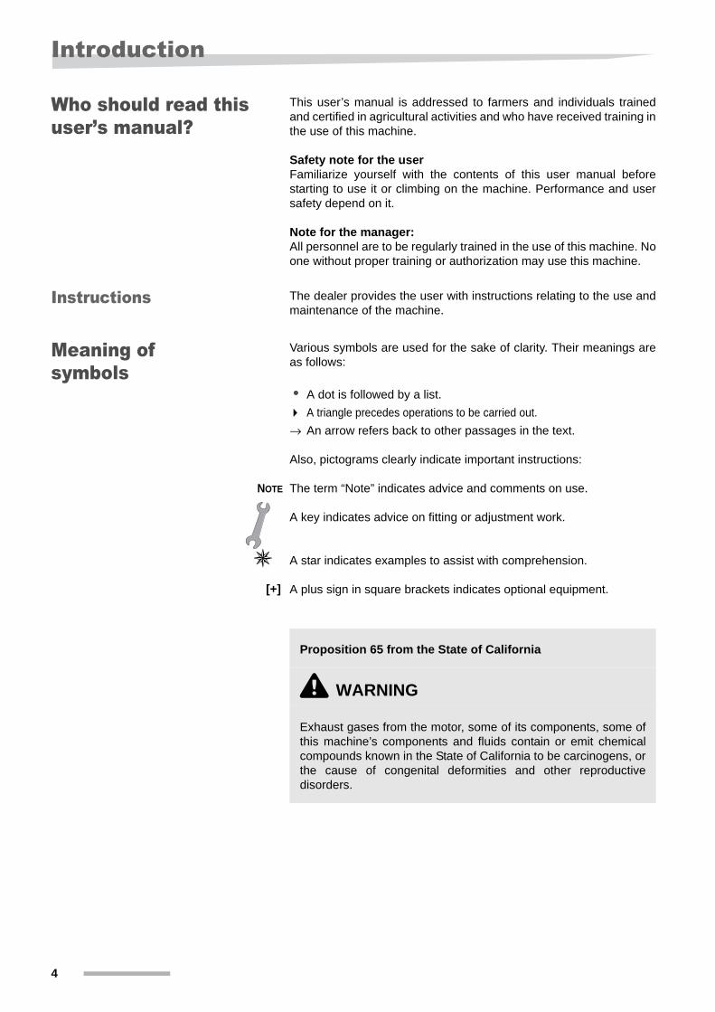
Meaning of symbols
Various symbols are used for the sake of clarity. Their meanings are as follows:
• A dot is followed by a list.
A triangle precedes operations to be carried out.
→ An arrow refers back to other passages in the text.
Also, pictograms clearly indicate important instructions:
NOTE The term “Note” indicates advice and comments on use.
A key indicates advice on fitting or adjustment work.
A star indicates examples to assist with comprehension.
A plus sign in square brackets indicates optional equipment.
Proposition 65 from the State of California
\ WARNING
Exhaust gases from the motor, some of its components, some of this machine’s components and fluids contain or emit chemical compounds known in the State of California to be carcinogens, or the cause of congenital deformities and other reproductive disorders.
[+]
4

Safety
SafetyFor your safety This section contains general safety information. The various chapters in this user’s manual include specific safety instructions. Be sure to comply with all safety guidelines
• in the interest of your own safety,
• in the interest of the safety of others,
• to ensure the safety of the machine.
When handling agricultural machines, failure to follow instructions can result in multiple hazards. Therefore, always work with special care and never under pressure.
5

Safety
Note for the manager:As required by law, you should regularly inform those working on the machine of the existence of safety instructions.
NOTEThis symbol indicates the presence of technical and operational information regarding personal safety around the machine.
\ SAFETY PRIORITY
The “Safety priority” symbol is used in this manual and on the pictograms placed on the machine in order to warn the user of the presence of a risk of bodily injury. Read these instructions closely. It is essential that you read these instructions and the safety guidelines before assembling or using the machine.
\ HAZARD
The warning term HAZARD warning indicates an extremely hazardous situation, which if not avoided will lead to death or serious injury.
\ WARNING
The warning term WARNING indicates a potentially hazardous situation, which if not avoided could lead to death or serious injury. The hazards identified by the term WARNING present a lower risk of death or injury than those associated with the term HAZARD.
\ CAUTION
The warning term CAUTION indicates a potentially hazardous situation, which if not avoided could lead to more minor or moderate injuries. The term CAUTION may also be used as a means of notification against hazardous practices, which in certain situations can cause injury.
6
Safety
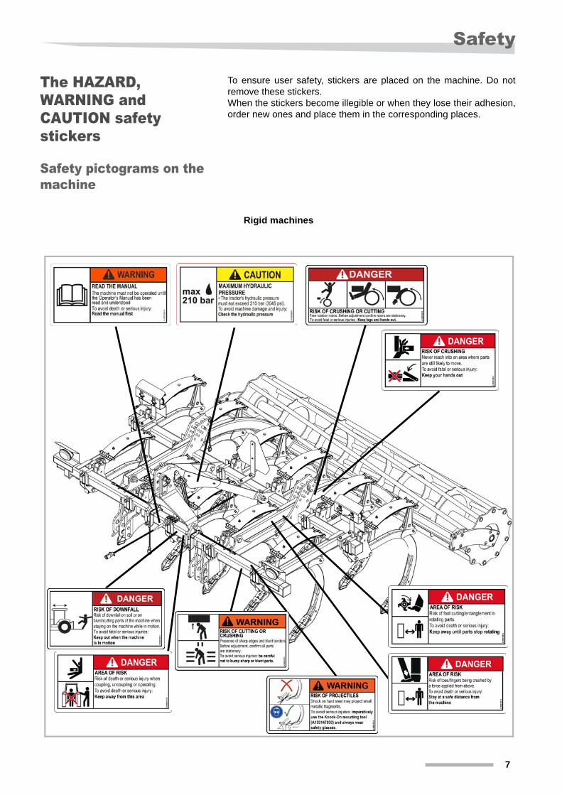
The HAZARD, WARNING and CAUTION safety stickers
To ensure user safety, stickers are placed on the machine. Do not remove these stickers. When the stickers become illegible or when they lose their adhesion, order new ones and place them in the corresponding places.
Safety pictograms on the machine
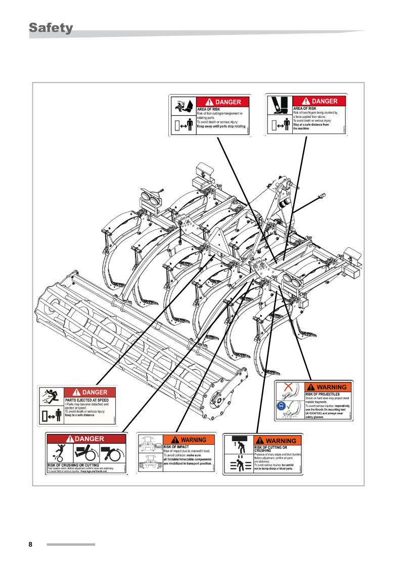
Rigid machines
7
Safety
8
Safety
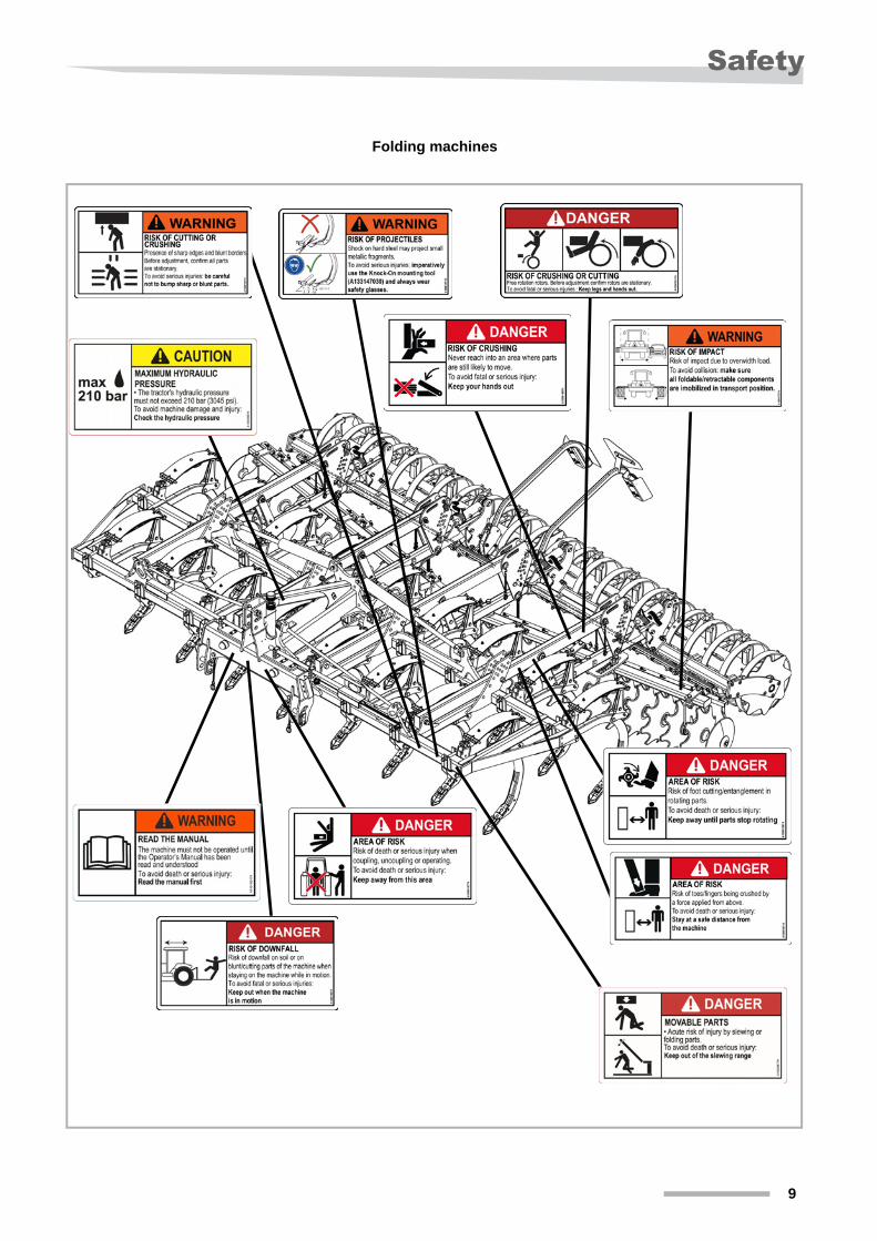
Folding machines
9
Safety
10

Safety
Meaning of safety symbols
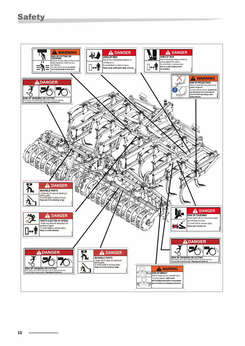
HAZARD:Pivoting or folding moving parts may cause serious injuries or death.Stand away from the range of movement of all pivoting parts.
HAZARD:Rotating parts can cause serious injuries or death.Stand away from the range of movement of all rotating parts.
HAZARD:Hazardous zoneRisk of cuts/feet getting tangled in the rotating parts. In order to avoid all serious or fatal injuries: Maintain a safe distance between you and the machine until all rotating parts have been immobilized.
HAZARD:Risk of crushingThere is a danger of hands being crushed in an area where there are likely to be moving parts. In order to avoid all serious or fatal injuries: keep your hands away from these areas.
HAZARD:Hazardous zoneRisk of serious or fatal injury during machine hitching, unhitching or operations.In order to avoid all serious or fatal injuries: Remain outside this zone.
HAZARD:Hazardous zoneRisk of crushed toes/fingers by a force applied from above.In order to avoid all serious or fatal injuries: maintain a safe distance between you and the machine.
11
Safety
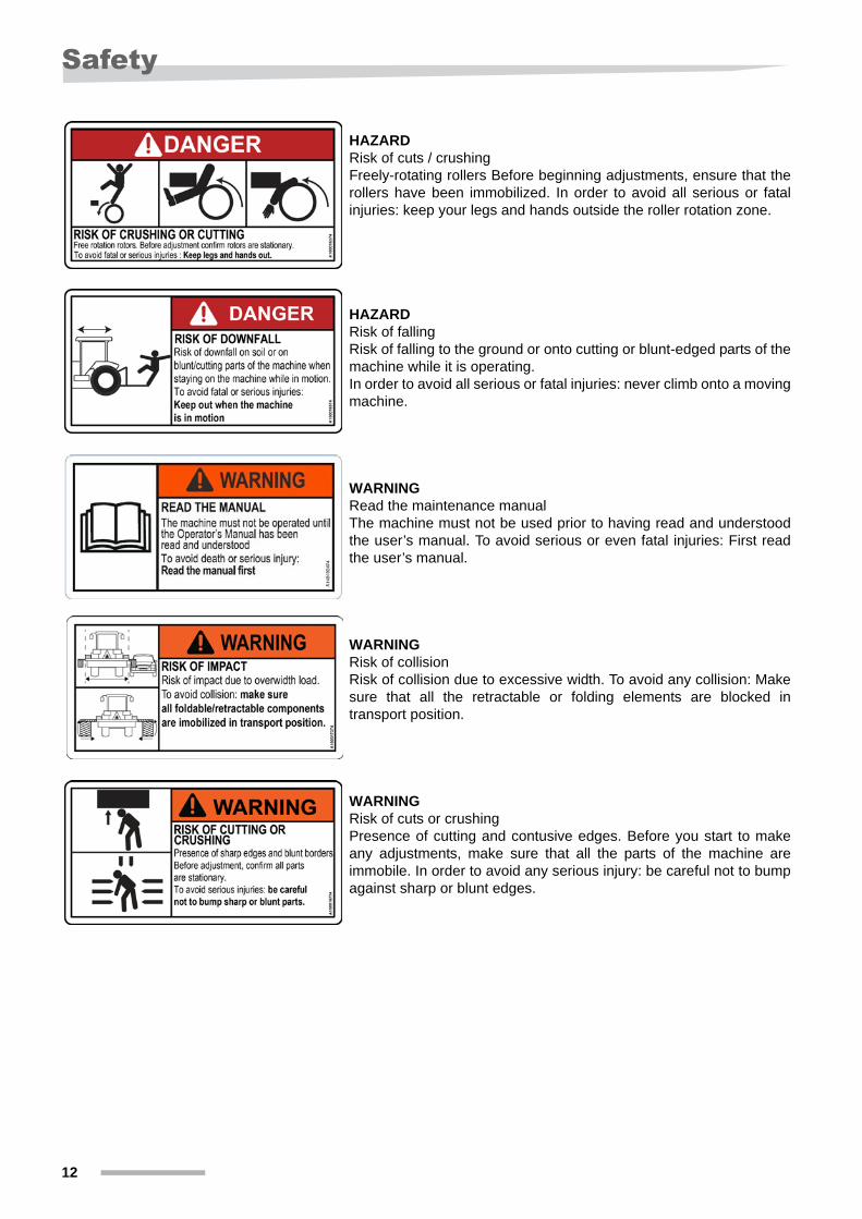
HAZARDRisk of cuts / crushingFreely-rotating rollers Before beginning adjustments, ensure that the rollers have been immobilized. In order to avoid all serious or fatal injuries: keep your legs and hands outside the roller rotation zone.
HAZARDRisk of fallingRisk of falling to the ground or onto cutting or blunt-edged parts of the machine while it is operating.In order to avoid all serious or fatal injuries: never climb onto a moving machine.
WARNINGRead the maintenance manualThe machine must not be used prior to having read and understood the user’s manual. To avoid serious or even fatal injuries: First read the user’s manual.
WARNINGRisk of collisionRisk of collision due to excessive width. To avoid any collision: Make sure that all the retractable or folding elements are blocked in transport position.
WARNINGRisk of cuts or crushingPresence of cutting and contusive edges. Before you start to make any adjustments, make sure that all the parts of the machine are immobile. In order to avoid any serious injury: be careful not to bump against sharp or blunt edges.
12

Safety
WARNINGRisk of projected debrisMetal fragments may be projected if you hit the coulters directly with a hammer.To avoid any serious injury: systematically use the Knock-On tool (A133147030) and always be sure to wear protective safety glasses.
CAUTIONMaximum hydraulic pressureThe tractor’s hydraulic pressure must not exceed 210 bar (3,045 psi).To avoid damage to the machine and injuries: check the hydraulic pressure.
13
Safety
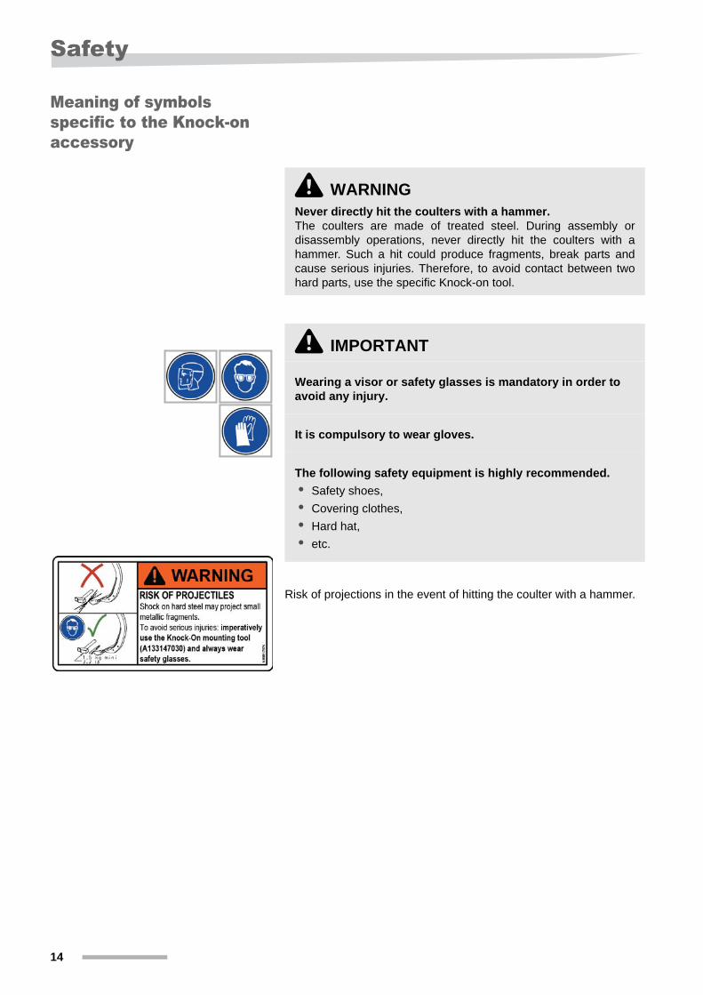
Meaning of symbols specific to the Knock-on accessory
Risk of projections in the event of hitting the coulter with a hammer.
\ WARNINGNever directly hit the coulters with a hammer.The coulters are made of treated steel. During assembly or disassembly operations, never directly hit the coulters with a hammer. Such a hit could produce fragments, break parts and cause serious injuries. Therefore, to avoid contact between two hard parts, use the specific Knock-on tool.
\ IMPORTANT
Wearing a visor or safety glasses is mandatory in order to avoid any injury.
It is compulsory to wear gloves.
The following safety equipment is highly recommended.
• Safety shoes,
• Covering clothes,
• Hard hat,
• etc.
14
Safety
Signaling systems for North America
Signaling systems, panels and stickers are installed on the machine in order to ensure complete road safety. The signaling systems must always be functional. Under no circumstances are you to remove the panels and stickers, but instead you must replace them if they are missing or illegible. You can order new stickers just like a spare part from your specialist dealer.The user must ensure that the tractor/machine unit is compliant with current prescriptions regarding machine transport on the road network.
Signaling systems
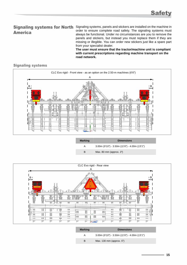
CLC Evo rigid - Front view - as an option on the 2.50-m machines (6’6”)
A
B B
Marking Dimensions
A 3.00m (9’10”) - 3.50m (11’6”) - 4.00m (13’1”)
B Max. 80 mm (approx. 3”)
CLC Evo rigid - Rear view
B B
A
Marking Dimensions
A 3.00m (9’10”) - 3.50m (11’6”) - 4.00m (13’1”)
B Max. 130 mm (approx. 5”)
15
Safety
A
B B
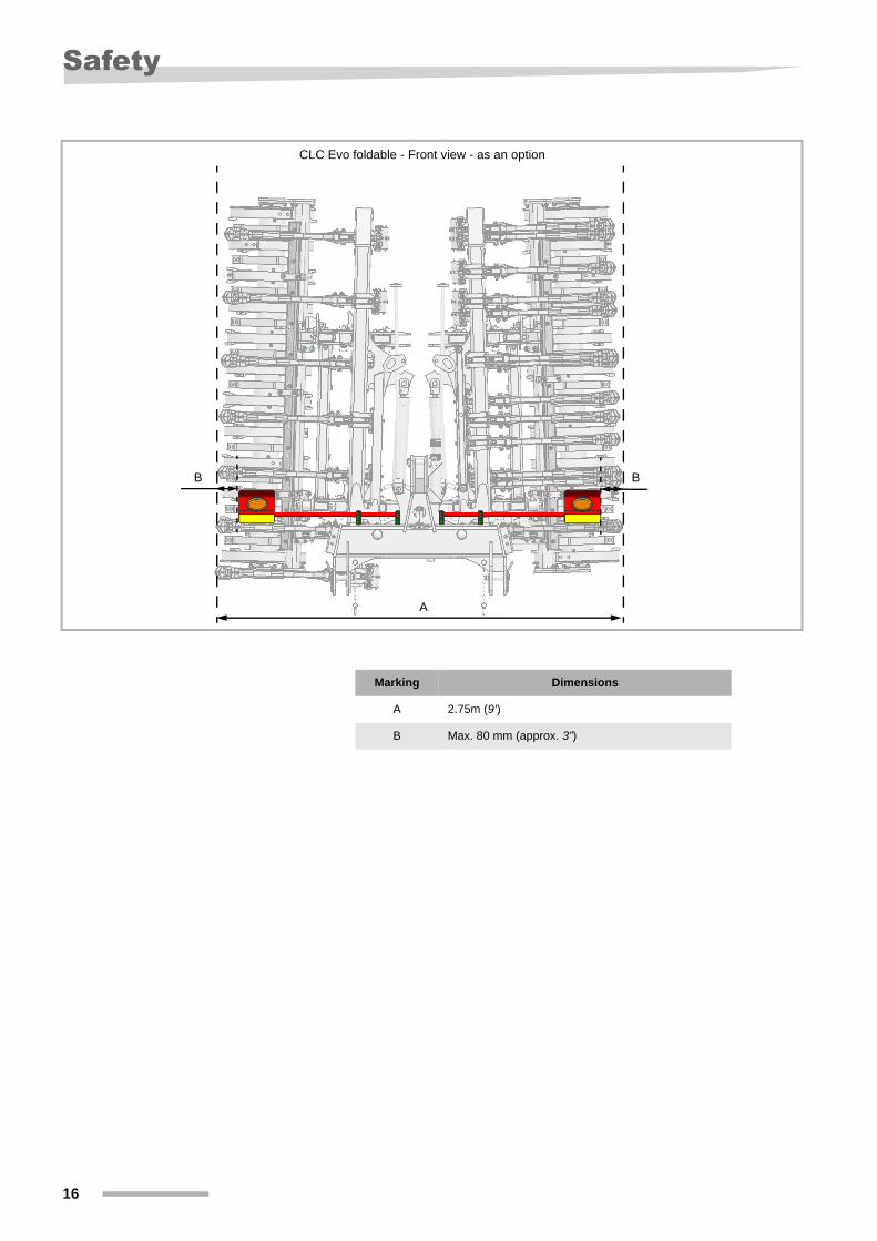
CLC Evo foldable - Front view - as an option
Marking Dimensions
A 2.75m (9’)
B Max. 80 mm (approx. 3”)
16
Safety
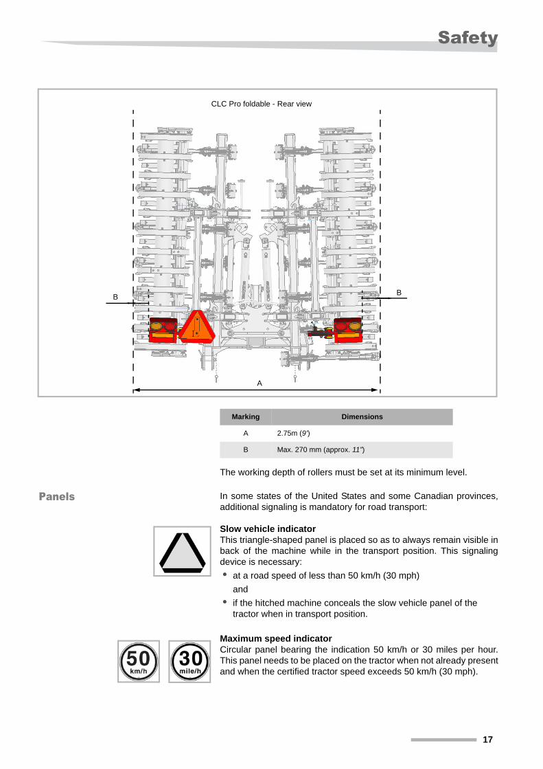
The working depth of rollers must be set at its minimum level.
Panels In some states of the United States and some Canadian provinces, additional signaling is mandatory for road transport:
Slow vehicle indicatorThis triangle-shaped panel is placed so as to always remain visible in back of the machine while in the transport position. This signaling device is necessary:
• at a road speed of less than 50 km/h (30 mph)
and
• if the hitched machine conceals the slow vehicle panel of the tractor when in transport position.
Maximum speed indicatorCircular panel bearing the indication 50 km/h or 30 miles per hour. This panel needs to be placed on the tractor when not already present and when the certified tractor speed exceeds 50 km/h (30 mph).
A
BB
CLC Pro foldable - Rear view
Marking Dimensions
A 2.75m (9’)
B Max. 270 mm (approx. 11”)
17
Safety
Safety rules
General recommen-dations
Before starting up, check that the machine is not endangering any persons and that the protection and safety devices (e.g. guards, hoods, warning labels, etc.) are in place and functional.
Before you start work, familiarize yourself with all the equipment, controls and functions on your machine. Once you have started, it is too late.
If an operating incident occurs:
Shut down the machine immediately.
Identify the cause of the incident.
Carry out repairs out before starting up the machine again.
No work should be attempted on the machine delivered unless:
• all measures have been taken to prevent unintentional start-up (uncouple the power take-off and/or hydraulic hoses, tractor engine switched off, for example).
• chocks have been placed under the frame to prevent it falling,
• the vehicle has been immobilized using the appropriate systems.
Before leaving the tractor:
Put the machine on the ground.
Activate the hand brake.
Remove the ignition key.
No one should stand between the tractor and the machine unless the vehicle is immobilized (hand brake, chocks, etc.), the engine is switched off and the ignition key removed.
18
Safety
Hitching
Follow instructions for hitching to the letter:
• when maneuvering, select the tractor’s lowest possible forward speed,
• the type of tractor hitch should be adapted to suit the machine’s hitch,
• when coupling, position the tractor’s hydraulic controls such that the hitch does not move during handling,
• the hitch must be locked and should not come detached by itself in the lower position.
The weight distribution is altered when the machine is hitched. The maximum load per vehicle axle (see manufacturer’s notice) should not be exceeded. If there is insufficient loading on the front axle, extra weights must be installed, so that control over the vehicle’s steering is retained.
When hitching or unhitching the tool, put any support equipment provided in place to prevent the machine from becoming unbalanced.
\ HAZARD
Never stand between the machine and the tractor during maneuvers.No one should stand between the tractor and the machine when maneuvering the tractor or during lifting operations. This could cause serious injury or even death.
19
Safety
Transport
Regulations
• Respect the driving code at all times when on the road on the road network.
• Check that your hitch meets local road safety requirements. If necessary, you are responsible for fitting and testing transport equipment (e.g. lighting, signals, guards, etc.) corresponding to the characteristics of your tractor-machine assembly and the applicable statutory requirements.
• Ensure that the machine’s dimensions are compatible with the highway code.
Passenger transportationCarrying passengers on the working tool or during transport is prohibited.
BrakingFor all movements, brakes must be coupled (no single wheel braking).
Trips off the farm fieldNo movement should be made outside an agricultural field or close to people, until folding extensions or folding or tipping accessories (where they exist) have been locked in the transport position.
HydraulicsIn transit, the hydraulic hoses of the folding jacks must be disconnected to prevent accidental unfolding.
Lifting
• During transport, lock the lower lift arms to prevent any sideways movement.
• During travel, the lift control must be positioned, so as to prevent the tool from being accidentally lowered.
AxleFor machines with a transport axle, secure the locking system in place prior to traveling on the road.
Locking of hydraulic jacksOn the machines fitted with locking devices, verify that the foldable parts of the machine have been correctly locked and moreover that the hydraulic safety equipment is well locked.
\ IMPORTANTMachine movementOn a curved road section, beware of machine movements as well as a shifting of the load. Adjust your forward speed accordingly.
20
Safety
Use\ HAZARDAvoid all contact of the machine with electrical voltage lines.Any contact with electrical voltage lines can cause serious or even fatal injuries. Take all necessary precautions in order to avoid any contact while handling the machine adjacent to electrical voltage lines.
\ WARNINGBe mindful of the return to the initial position of locked tine.Any tine that is abnormally blocked in the raised position may suddenly return to its position and is therefore a source of serious danger.
Keep away from the tine and never stand in its return path.
Raise the machine to eliminate any blockages.
When the tine is returned to low position, check that it is fully tightened and does not lock up.
If the tine remains locked, do not try to release it. Call a technician.
Stay outside the zone where the machine’s foldable parts are in motion.No one should enter the folding extensions area or folding or tipping (where present) accessories movement area, until they have been locked by the system provided for this purpose. The system may be chain, a pin, a rigid connecting rod or a double control valve.
Do not take actions on a moving machine.Any work on the machine is prohibited while the tractor is in motion. Keep a safety distance of at least 5.00 m (16’4”) from the machine in motion (forward movement, movement of any part of the machine, movement of the tractor hitch).
Verify the peripheral areas of both the machine and tractor before starting up.Before starting up:
Ensure that there is no one in the immediate vicinity (children, etc.).
Ensure that you have sufficient visibility.
Wear safety shoes and maintain a safe distance when adjusting machines fitted with discs.For machines fitted with covering discs, border discs, folding tines, leveling boards, track erasers or any other accessory that can be vertically adjusted, it is advisable to respect a safety distance, as the equipment could accidentally fall when being adjusted. Wearing safety shoes is recommended.
21

Safety
Safety for children
\ WARNING
Do not assume that children will remain calmly in place where you last saw them. Remain vigilant and turn off the motor if children are present in your work space. Never let children play on the machine or use it.
\ IMPORTANTAdapt your speed when the ground is sloped.In the event of use on uneven terrain, the tractor can deviate from its path if it encounters a hole, ditch or other irregularity. To remedy this problem, be sure to always drive at a speed adapted to the uneven ground.
Just one person is allowed on the tractor while it is running.Only allow one person, the operator, on the tractor when it and the tool are in operation.
22
Safety
Maintenance
It is strictly forbidden to disassemble springs used as safety devices for working parts: This operation must only be performed by specialists.
For machines fitted with foldable extensions: Strictly follow the instruc-tions in this user’s manual for the assembly, disassembly and adjustment.
Before carrying out any welding works:
Disconnect the electrical boxes (if present).
Disconnect the tractor alternator and battery if it is hitched.
Regularly check that bolts are tight, tire pressures are correct and the hydraulic circuit is in good condition.
Be sure to never direct the high-pressure cleaning jet directly onto the following components, so as to prevent their deterioration:
• bearings,
• hydraulic hoses,
• electrical boxes
• any sensitive machine component.
\ HAZARDApply the brakes or immobilization system prior to any actions taken on the tractor-tool assembly.Be sure to always apply the brakes or the vehicle immobilization system prior to any action taken within the radius of the tractor-tool assembly. Failing to do so may cause serious or even fatal injuries.
\ WARNINGBeware of sharp edges and corners.When changing parts on the machine, you should pay attention to all parts with sharp edges or corners. We recommend that you wear safety equipment (hard hat, safety shoes, gloves, etc.) in order to avoid any injury.
\ IMPORTANTBeware of the return path of the high-pressure cleaning jet.While cleaning the machine, beware of the return path of the high-pressure cleaning jet on some of the surfaces. This might cause bruises and contusions.
23

Safety
Unhitching
In order to avoid any hazard during unhitching:
Immobilize the tractor,
lower the machine,
engage the parking brake,
make sure that the machine is on flat and sufficiently stable ground.
operate the tractor’s hydraulic lift slowly and carefully,
Connect or disconnect hydraulic tubes, only if there is no pressure in the tractor’s and machine’s hydraulic system.
\ WARNING
Never stand between the tractor and the machine during unhitching. Before unhitching the machine, be sure that no one is positioned between the machine and the tractor. Individuals may get pinned between the tractor and machine, thereby leading to serious or even fatal injuries.
24

Safety
Hydraulic installation
For further information, refer to Chapter "Replacement of the hydraulic system parts" page 82.
Other instructions Follow instructionsIn addition to the instructions listed above, always follow:
• Accident prevention regulations
• generally recognized safety regulations, occupational health requirements and road traffic regulations,
• the notes that can be found in the user manual,
• instructions for use, maintenance and servicing.
\ HAZARD
Any action taken on the hydraulic system must always be performed by a trained and certified technician.
25

Presentation of the machine
Presentation of the machineField of application
This machine is considered to be interchangeable equipment within the meaning of European directive 2006/42/EC and is considered to be agricultural equipment within the meaning of directive ASABE S390.
This chapter contains general information about your machine as well as information concerning the following points:
• Usage clause.
• Characteristics.
• Description of machine components.
• Technical data.
Usage clause This machine has been designed solely for normal agricultural use, i.e. for cultivating farmland. Any other use or misuse, for example, transport, land clearing or transmission of power to another machine is considered to be contrary to the intended use.The manufacturer and specialist dealer decline any responsibility for damage caused by use other than normal use. The user assumes all risks.
Compliance with the conditions of use includes compliance with the manufacturer’s user instructions.
The safety instructions (detailed above) and rules regarding general safety, occupational health and road traffic must also be followed.
Modifications to the tool made by the customer or the use of spare parts or accessories that are not original parts will void the manufac-turer’s liability for all damage resulting from the modification.
The manufacturer cannot be held liable for damage resulting from incorrect settings, choice of equipment, seed, fertilizer, treatments or farming strategy or for any other damage not directly related to the machine.
26
Presentation of the machine
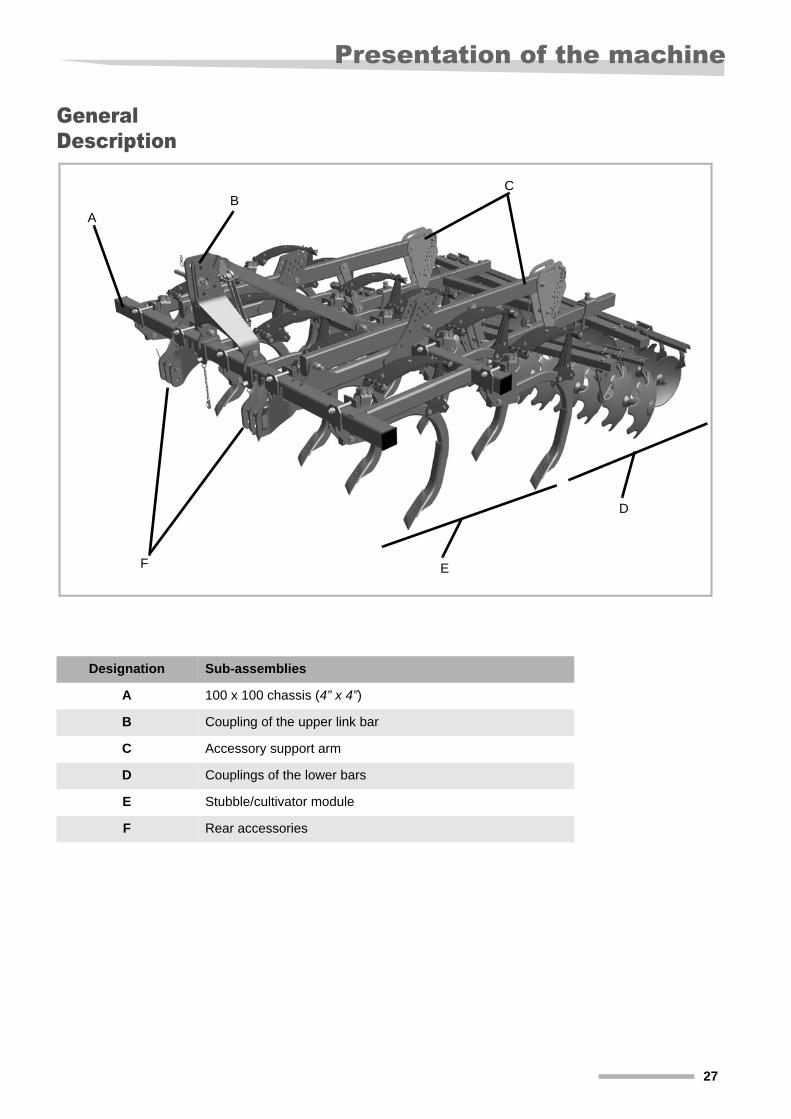
General Description
AB
C
D
EF
Designation Sub-assemblies
A 100 x 100 chassis (4” x 4”)
B Coupling of the upper link bar
C Accessory support arm
D Couplings of the lower bars
E Stubble/cultivator module
F Rear accessories
27
Presentation of the machine
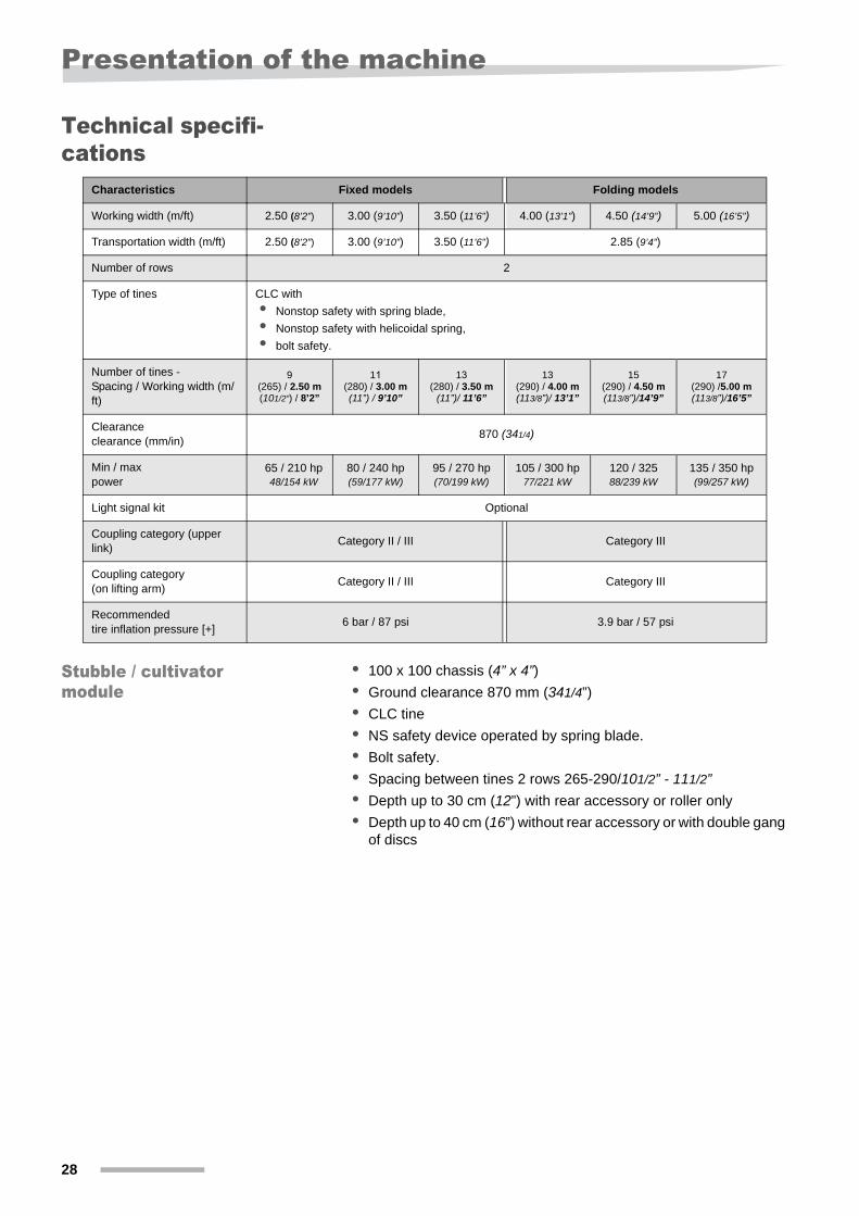
Technical specifi-cations
Stubble / cultivator module
• 100 x 100 chassis (4” x 4”)• Ground clearance 870 mm (341/4”)
• CLC tine
• NS safety device operated by spring blade.
• Bolt safety.
• Spacing between tines 2 rows 265-290/101/2” - 111/2”• Depth up to 30 cm (12”) with rear accessory or roller only
• Depth up to 40 cm (16”) without rear accessory or with double gang of discs
Characteristics Fixed models Folding models
Working width (m/ft) 2.50 (8’2”) 3.00 (9’10”) 3.50 (11’6”) 4.00 (13’1”) 4.50 (14’9”) 5.00 (16’5”)
Transportation width (m/ft) 2.50 (8’2”) 3.00 (9’10”) 3.50 (11’6”) 2.85 (9’4”)
Number of rows 2
Type of tines CLC with
• Nonstop safety with spring blade,
• Nonstop safety with helicoidal spring,
• bolt safety.
Number of tines - Spacing / Working width (m/ft)
9(265) / 2.50 m(101/2”) / 8’2”
11(280) / 3.00 m(11”) / 9’10”
13(280) / 3.50 m
(11”)/ 11’6”
13(290) / 4.00 m(113/8”)/ 13’1”
15(290) / 4.50 m(113/8”)/14’9”
17(290) /5.00 m(113/8”)/16’5”
Clearance clearance (mm/in)
870 (341/4)
Min / max power
65 / 210 hp48/154 kW
80 / 240 hp(59/177 kW)
95 / 270 hp(70/199 kW)
105 / 300 hp77/221 kW
120 / 32588/239 kW
135 / 350 hp(99/257 kW)
Light signal kit Optional
Coupling category (upper link)
Category II / III Category III
Coupling category (on lifting arm)
Category II / III Category III
Recommended tire inflation pressure [+]
6 bar / 87 psi 3.9 bar / 57 psi
28
Presentation of the machine
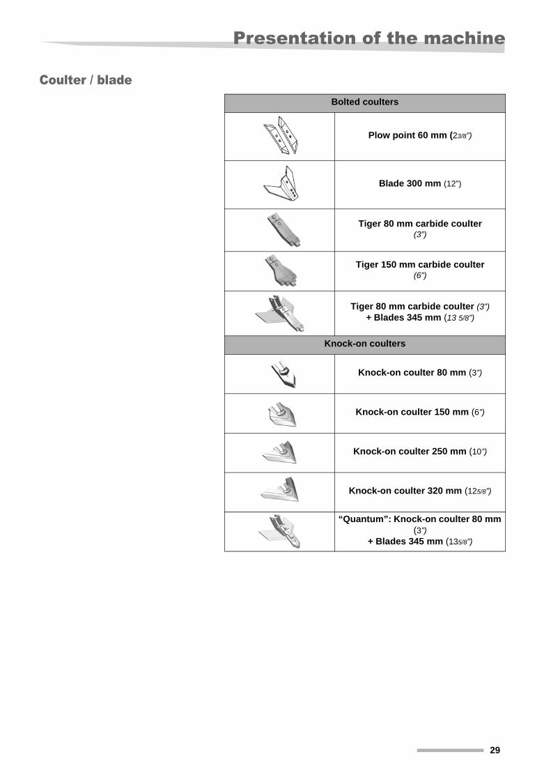
Coulter / bladeBolted coulters
Plow point 60 mm (23/8”)
Blade 300 mm (12”)
Tiger 80 mm carbide coulter (3”)
Tiger 150 mm carbide coulter (6”)
Tiger 80 mm carbide coulter (3”)+ Blades 345 mm (13 5/8”)
Knock-on coulters
Knock-on coulter 80 mm (3”)
Knock-on coulter 150 mm (6”)
Knock-on coulter 250 mm (10”)
Knock-on coulter 320 mm (125/8”)
“Quantum”: Knock-on coulter 80 mm (3”)
+ Blades 345 mm (135/8”)
29
Presentation of the machine
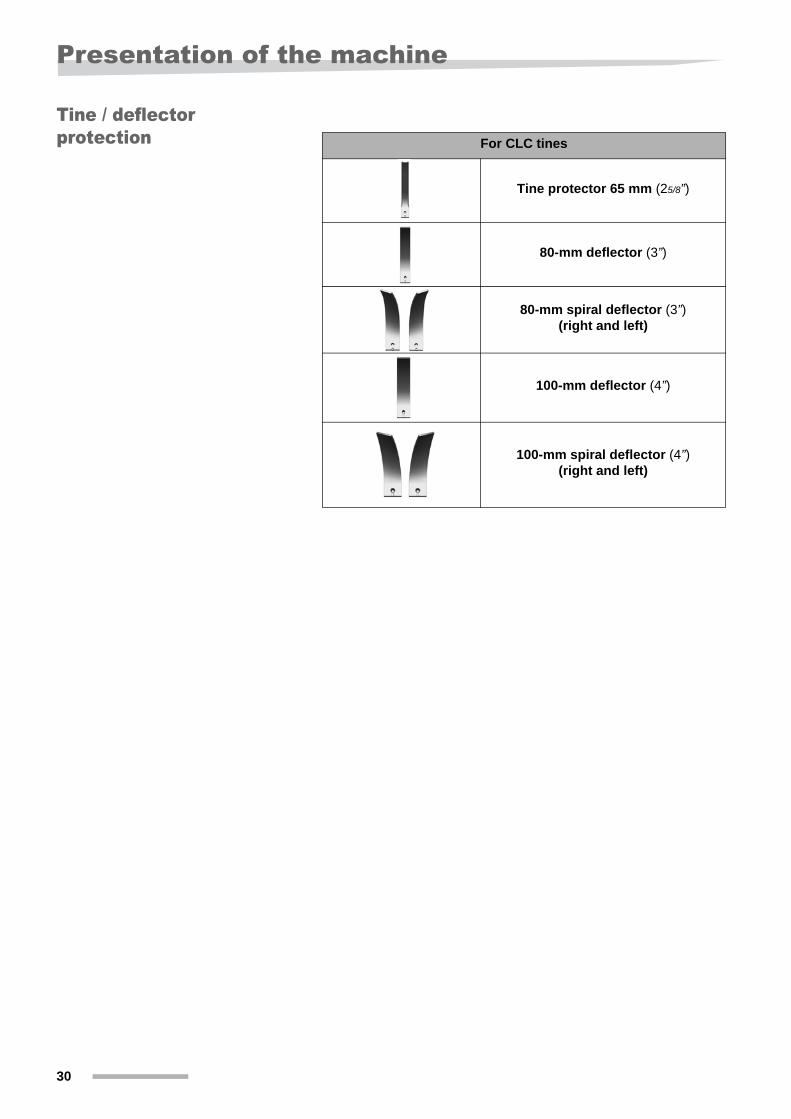
Tine / deflector protection For CLC tines
Tine protector 65 mm (25/8”)
80-mm deflector (3”)
80-mm spiral deflector (3”)(right and left)
100-mm deflector (4”)
100-mm spiral deflector (4”)(right and left)
30
Presentation of the machine
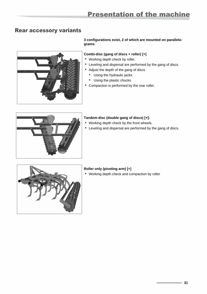
Rear accessory variants3 configurations exist, 2 of which are mounted on parallelo-grams:
Combi-disc (gang of discs + roller) [+]
• Working depth check by roller.
• Leveling and dispersal are performed by the gang of discs.
• Adjust the depth of the gang of discs
• Using the hydraulic jacks
• Using the plastic chocks
• Compaction is performed by the rear roller.
Tandem-disc (double gang of discs) [+]:
• Working depth check by the front wheels.
• Leveling and dispersal are performed by the gang of discs.
Roller only (pivoting arm) [+]
• Working depth check and compaction by roller
31
Presentation of the machine
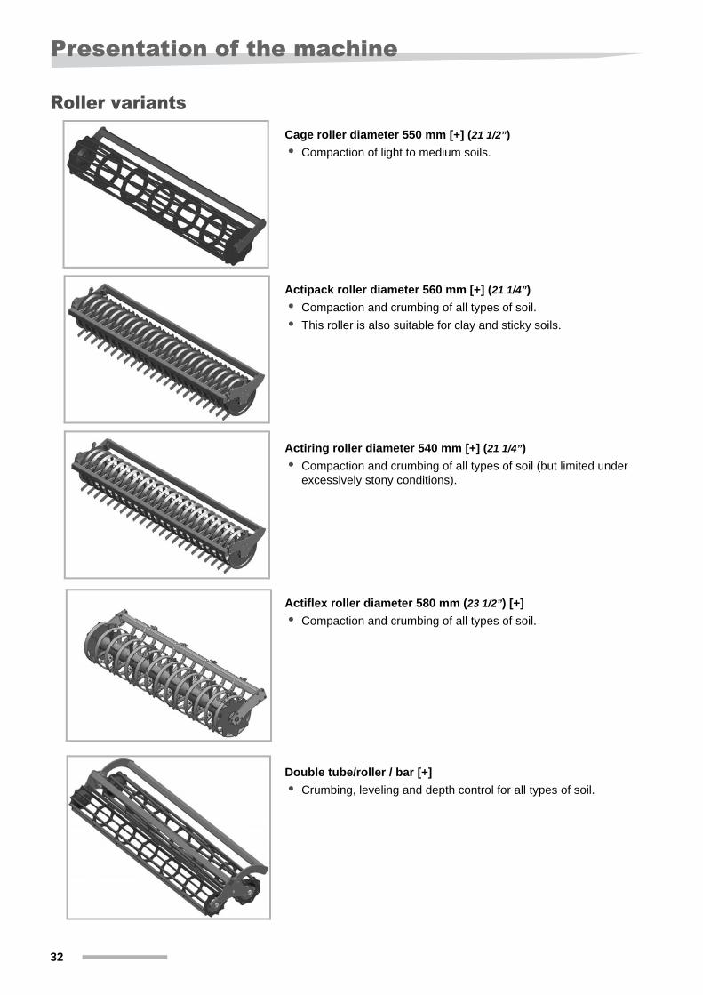
Roller variantsCage roller diameter 550 mm [+] (21 1/2”)
• Compaction of light to medium soils.
Actipack roller diameter 560 mm [+] (21 1/4”)
• Compaction and crumbing of all types of soil.
• This roller is also suitable for clay and sticky soils.
Actiring roller diameter 540 mm [+] (21 1/4”)
• Compaction and crumbing of all types of soil (but limited under excessively stony conditions).
Actiflex roller diameter 580 mm (23 1/2”) [+]
• Compaction and crumbing of all types of soil.
Double tube/roller / bar [+]
• Crumbing, leveling and depth control for all types of soil.
32
Presentation of the machine
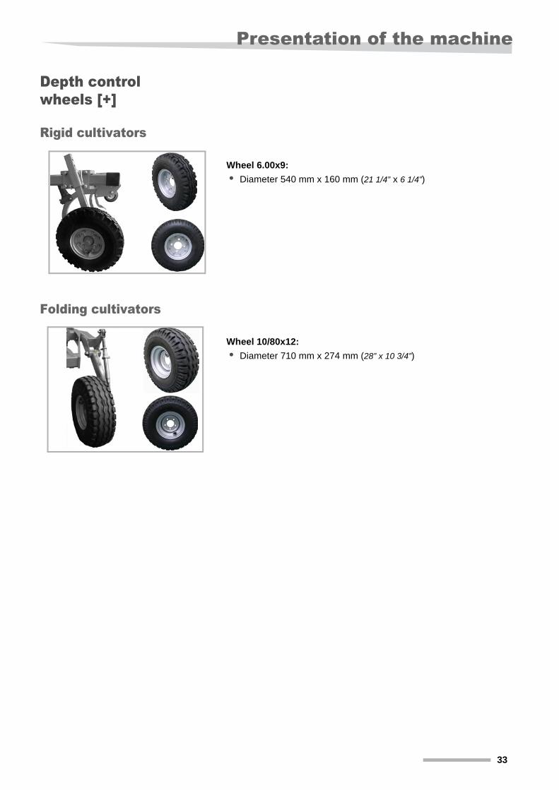
Depth control wheels [+]
Rigid cultivators
Wheel 6.00x9:
• Diameter 540 mm x 160 mm (21 1/4” x 6 1/4”)
Folding cultivators
Wheel 10/80x12:
• Diameter 710 mm x 274 mm (28” x 10 3/4”)
33
Presentation of the machine
Other optional equipment [+]
Signaling and lightingAll lights, reflectors, license plates and signaling or warning panels on the tractor must be perfectly visible. If this is not possible, you must install lights and a license plate on the machine.
If necessary, contact your dealer to order a new lighting kit.
Seeder for vegetation cover
• Enables vegetation cover.
• Broadcast seeding.
For more information on safety conditions, assembly, use and maintenance of the seeder, please refer to its user manual.
Distribution of right and left deflectors
Spiral deflectors may equip the lateral tines or all the tines of the machine.
The optimal distribution of these deflectors depends on the accessory type, working conditions (type of ground, depth, speed...), it needs to be adapted during commissioning.
If required, it is possible to invert one or several pairs of deflectors in order to improve mixing or leveling quality.
The factory set-up involves the mounting of deflectors by row. This set-up promotes mixing and balance of soil flows.
Machines with two tine rows:
• The exterior tines direct soil flows towards the interior.
• First row of tines: All the deflectors are oriented to the left. Deflectors spiraled to the left are used.
• Second row of tines: All the deflectors are oriented to the right. Deflectors spiraled to the right are used.
34
Presentation of the machine
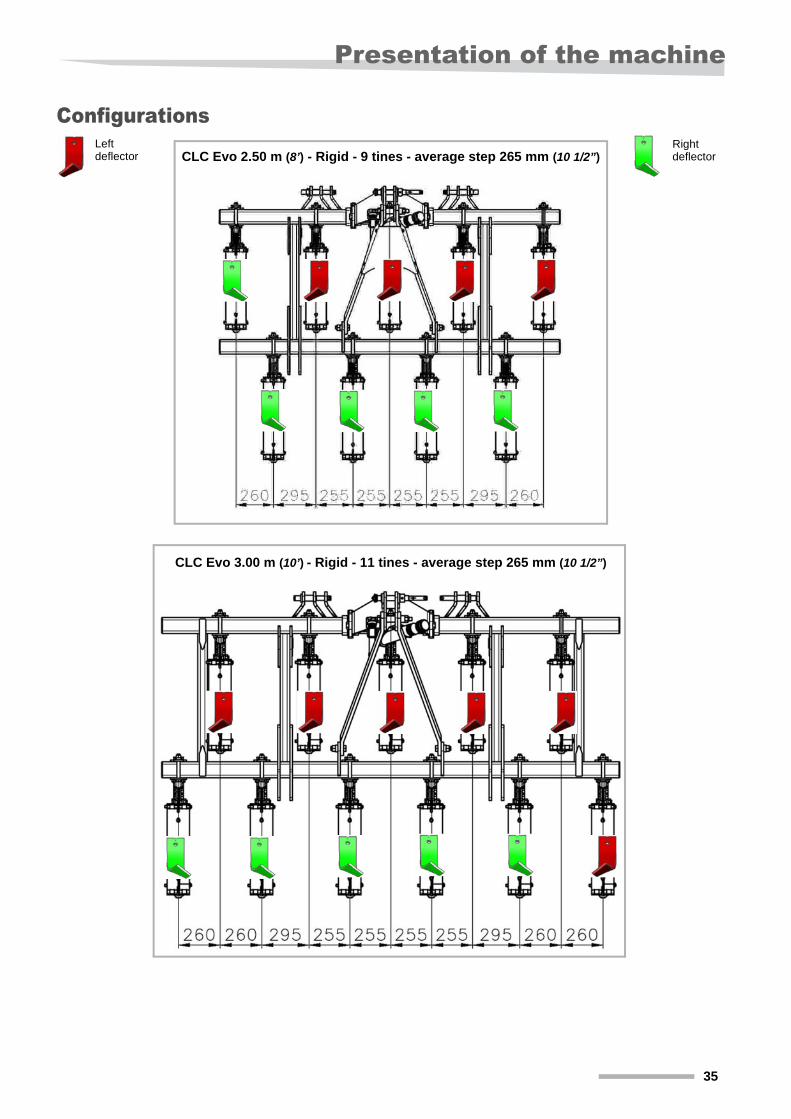
Configurations
CLC Evo 2.50 m (8’) - Rigid - 9 tines - average step 265 mm (10 1/2”)Left deflector
Right deflector
CLC Evo 3.00 m (10’) - Rigid - 11 tines - average step 265 mm (10 1/2”)
35
Presentation of the machine
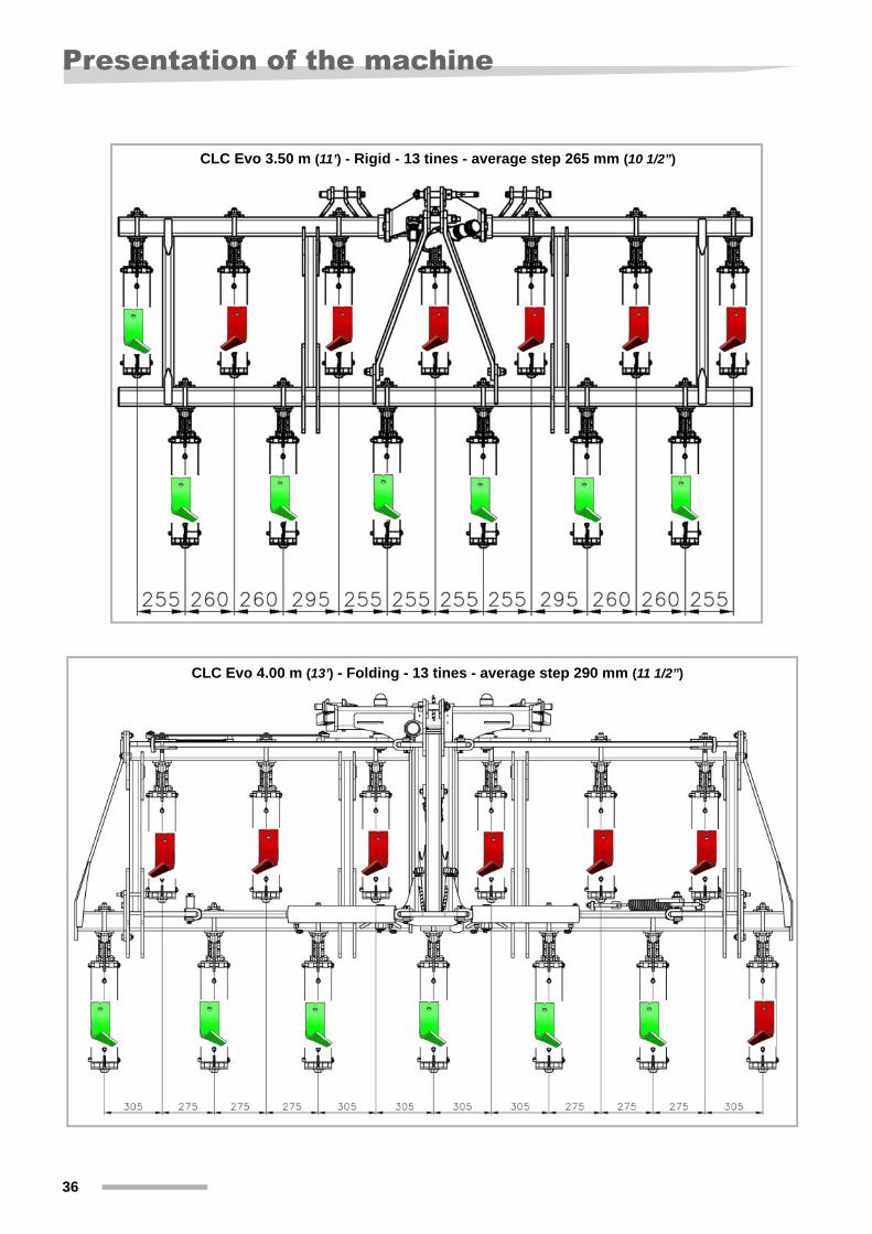
CLC Evo 3.50 m (11’) - Rigid - 13 tines - average step 265 mm (10 1/2”)
CLC Evo 4.00 m (13’) - Folding - 13 tines - average step 290 mm (11 1/2”)
36
Presentation of the machine
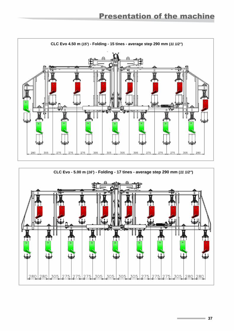
CLC Evo 4.50 m (15’) - Folding - 15 tines - average step 290 mm (11 1/2”)
CLC Evo - 5.00 m (16’) - Folding - 17 tines - average step 290 mm (11 1/2”)
37
Safety
SafetyUnhitching
Hydraulic systemThe hydraulic system is pressurized.
When connecting the hydraulic system:
Ensure that the hydraulic systems of both the tractor and machine are not pressurized.
Connect the hydraulic system, following the instructions in the user manual.
Identify the connectors using the color code to avoid incorrect connections (inverting the functions could cause accidents).
Before any intervention on the hydraulic system:
Lock the folding extension and all the hydraulically controlled accessories in rest position.
Reduce the pressure.
Turn off the tractor engine.
Other instructions Beyond the above instructions, ensure compliance with the following:
• accident prevention instructions,
• widely accepted safety rules, workplace safety prescriptions and guidelines in effect regarding road safety,
• instructions indicated in use, maintenance and service manuals.
\ DANGER
Heightened risk of injury when uncoupling the machine.To avoid injury:
Immobilize the tractor,
lower the machine,
engage the parking brake,
make sure that the machine is on flat and sufficiently stable ground.
operate the tractor hydraulic lift slowly and carefully,
connect or disconnect the hydraulic connectors to/from the tractor hydraulic system only when the tractor/machine assembly is no longer pressurized.
38
Acceptance and assembly
Acceptance and assemblyVerifications at the time of acceptance
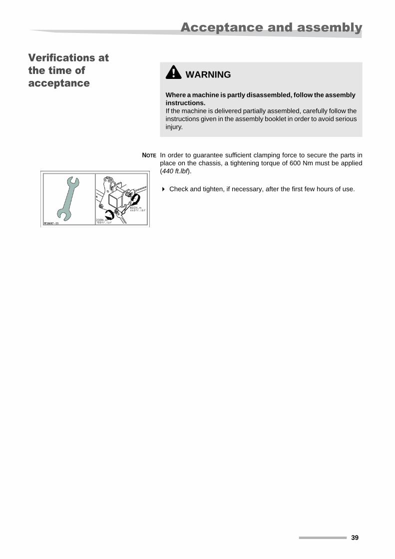
NOTE In order to guarantee sufficient clamping force to secure the parts in place on the chassis, a tightening torque of 600 Nm must be applied (440 ft.lbf).
Check and tighten, if necessary, after the first few hours of use.
\ WARNING
Where a machine is partly disassembled, follow the assembly instructions. If the machine is delivered partially assembled, carefully follow the instructions given in the assembly booklet in order to avoid serious injury.
39
Acceptance and assembly
Assembly of the arms
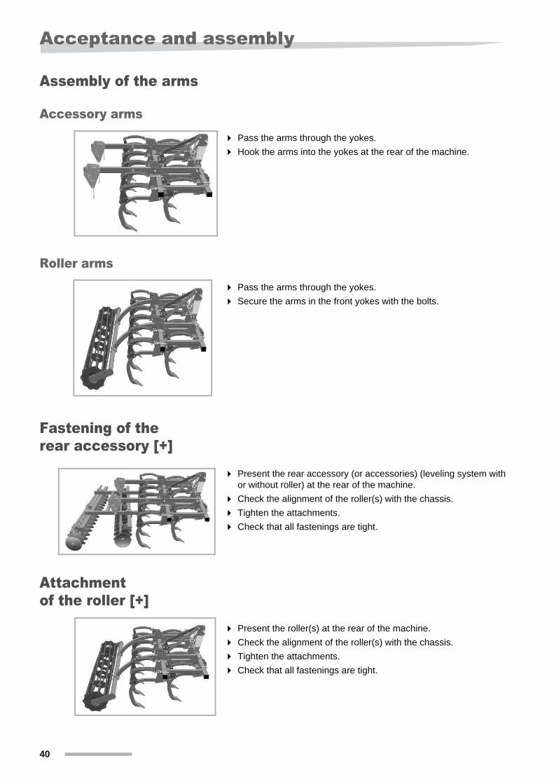
Accessory arms
Pass the arms through the yokes.
Hook the arms into the yokes at the rear of the machine.
Roller arms
Pass the arms through the yokes.
Secure the arms in the front yokes with the bolts.
Fastening of the rear accessory [+]
Present the rear accessory (or accessories) (leveling system with or without roller) at the rear of the machine.
Check the alignment of the roller(s) with the chassis.
Tighten the attachments.
Check that all fastenings are tight.
Attachment of the roller [+]
Present the roller(s) at the rear of the machine.
Check the alignment of the roller(s) with the chassis.
Tighten the attachments.
Check that all fastenings are tight.
40
Acceptance and assembly
Installing the rear struts
On folding machines
In order to save space, you may prefer to store the machine with the chassis folded using the set of storage struts.
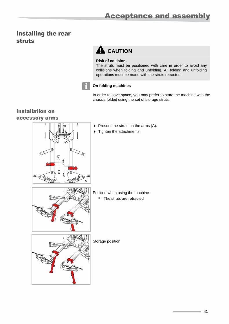
Installation on accessory arms
Present the struts on the arms (A).
Tighten the attachments.
Position when using the machine
• The struts are retracted
Storage position
\ CAUTION
Risk of collision. The struts must be positioned with care in order to avoid any collisions when folding and unfolding. All folding and unfolding operations must be made with the struts retracted.
A
41
Acceptance and assembly
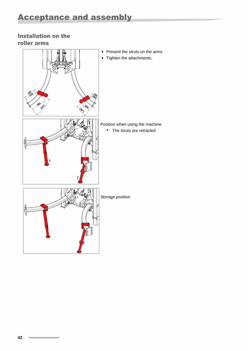
Installation on the roller arms
Present the struts on the arms.
Tighten the attachments.
Position when using the machine
• The struts are retracted
Storage position
42

Hitching
Hitching
Rigid machines On the rigid machines, adjust the bar on the third point to the
required coupling category.
Bring the tractor to the machine.
Couple the machine to the tractor lifter.
Adjust the tractor arms so that the machine has the least play possible to the right and left.
Connect the road signals connector, if present.
On the folding machines, if necessary, clean the hydraulic couplings to prevent impurities from entering the hydraulic circuit.
\ DANGER
Never stand between the tractor and the machine when coupling. It is extremely dangerous to stand between the machine and the tractor when coupling, you could be crushed. This could cause serious injury or even death.
Comply fully with safety instructions.By complying with the instructions you will be able to use your machine under optimum safety conditions.
Reference Designation
A Category 2
B Category 3
A
B
43
Hitching
Folding machines
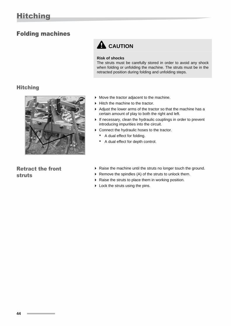
Hitching
Move the tractor adjacent to the machine.
Hitch the machine to the tractor.
Adjust the lower arms of the tractor so that the machine has a certain amount of play to both the right and left.
If necessary, clean the hydraulic couplings in order to prevent introducing impurities into the circuit.
Connect the hydraulic hoses to the tractor.
• A dual effect for folding.
• A dual effect for depth control.
Retract the front struts
Raise the machine until the struts no longer touch the ground.
Remove the spindles (A) of the struts to unlock them.
Raise the struts to place them in working position.
Lock the struts using the pins.
\ CAUTION
Risk of shocksThe struts must be carefully stored in order to avoid any shock when folding or unfolding the machine. The struts must be in the retracted position during folding and unfolding steps.
A
44

Lighting
LightingElectrical connections
Lighting for North America
The machine is fitted with lighting equipment for travel on roads. The various lights are attached to the tractor via a seven-pin connector. There must be a corresponding socket on the tractor:
If your tractor does not have the required socket for connecting the lighting, you must obtain one.
Please contact your specialist dealer.
Machine lighting is controlled from the tractor’s lighting controller:
Switch on the tractor’s parking or low beam lights to switch on the lights on the machine.
Pin-outs for SAE J560 connector
Connect the male plug for the 12V electrical supply to the 7-pin connector on the tractor.
\ IMPORTANT
Check the electrical cablesCheck the electrical cables regularly. They must not rub on any part of the machine or hang in space. Replace any torn or damaged electrical cables, they could damage the machine.
A Yellow
B Red
A B
C. Pin Cable Connector
1 White Ground; all lights
2 Black Not used
3 Yellow Left flashing yellow light (yellow)
4 Red Stop lights
5 Green Right flashing yellow light (yellow)
6 Brown Rear lights (red)
7 Blue Not used
45

Lighting
Lighting operation for North America
Check the lighting using the following table:
\ IMPORTANT
Comply with local requirements for road travel lighting equipment. Contact your specialist dealer, if the lighting does not function as recommended.
Tractor lightsMachine lights
Left yellow Left red Right red Right yellow
Lights off --- Off Off ---
Lights on --- Low intensity Low intensity ---
Flashers yellow off
Off --- --- Off
Flashers yellow on
Flashing (same speed as right)
--- --- Flashing (same speed as left)
Stop lights (for tractors fitted with them)
--- On On ---
Yellow flashers on No direction indicated (tractors with stop lights)
Flashing (same speed as right)
On OnFlashing (same speed as left)
Yellow flashers on No direction indicated (tractors without stop lights)
Flashing (same speed as right)
Off OffFlashing (same speed as left)
Direction indicated turning left
Quicker flashing speed
As per equipment fitted on tractor off, low intensity or flashing at the same frequency as the left-side light
Off or low intensity On, no flashing
Direction indicated turning right
On, no flashing Off or low intensity
As per equipment fitted on tractor off, low intensity or flashing at the same frequency as the right-side light
Quicker flashing speed
46
Transport
TransportSafety
Before traveling on public roads
Always comply with the Highway Code.
Remove plant debris, stones and large clumps of earth before driving on the road.
\ DANGER
Passenger transportation.It is strictly prohibited to transport individuals positioned on the machine.
\ WARNING
Read the safety instructions carefully prior to the transpor-tation step.Prior to transporting the machine on the road, you must carefully read the following safety instructions. Compliance with these instructions is essential and helps avoid accidents.
\ WARNING
Respect of applicable regulations concerning transport on public roads Respect applicable regulations when driving on public roads:
• The unit must be equipped with suitable warning signs, alarm and safety devices.
• The machine must comply with the transportation widths and authorized weights, as well as the axle loads, tire load limits and total weights allowed. Be sure that tractor handling has not been impaired.
• Even when the machine is in the transport position, there must be sufficient loading of the front axle.
Failure to comply with the applicable regulations engages the liability of the driver and the owner of the vehicle.
Controlled valve: Briefly actuate floating mode and ensure that the machine does not unfold.
\ CAUTION
On folding machines, make sure that the support legs have been retracted in the working position.For further details on how to retract the support legs, please refer to Chapters Adjusting the rear struts, page 64 and Adjust the front struts, page 65.
47
Transport
Respect the legal transportation width
Tipping elements Make sure that you fold back and lock all the tipping elements on the machine.
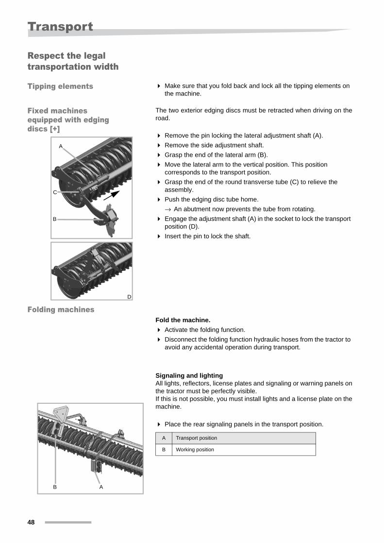
Fixed machines equipped with edging discs [+]
The two exterior edging discs must be retracted when driving on the road.
Remove the pin locking the lateral adjustment shaft (A).
Remove the side adjustment shaft.
Grasp the end of the lateral arm (B).
Move the lateral arm to the vertical position. This position corresponds to the transport position.
Grasp the end of the round transverse tube (C) to relieve the assembly.
Push the edging disc tube home.
→ An abutment now prevents the tube from rotating.
Engage the adjustment shaft (A) in the socket to lock the transport position (D).
Insert the pin to lock the shaft.
Folding machinesFold the machine.
Activate the folding function.
Disconnect the folding function hydraulic hoses from the tractor to avoid any accidental operation during transport.
Signaling and lightingAll lights, reflectors, license plates and signaling or warning panels on the tractor must be perfectly visible. If this is not possible, you must install lights and a license plate on the machine.
Place the rear signaling panels in the transport position.
A
B
C
D
B A
A Transport position
B Working position
48
Switching on
Switching on
Folding machines
After driving on the road, re-connect the hydraulic hoses of the chassis folding function to the tractor.
Unfold the frame.
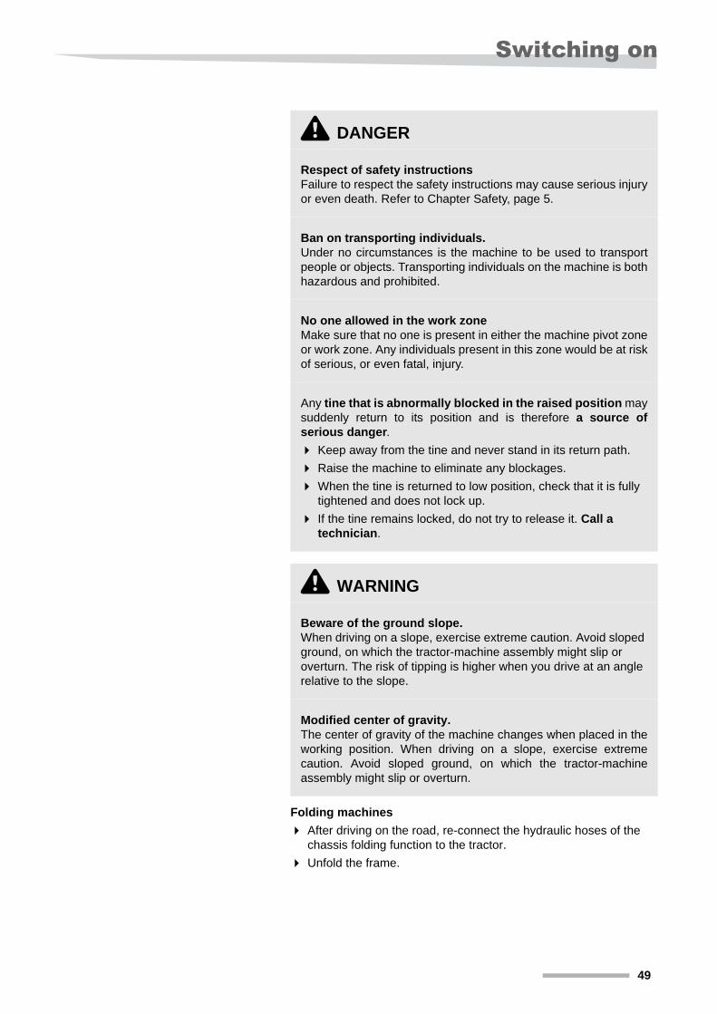
\ DANGER
Respect of safety instructions Failure to respect the safety instructions may cause serious injury or even death. Refer to Chapter Safety, page 5.
Ban on transporting individuals. Under no circumstances is the machine to be used to transport people or objects. Transporting individuals on the machine is both hazardous and prohibited.
No one allowed in the work zone Make sure that no one is present in either the machine pivot zone or work zone. Any individuals present in this zone would be at risk of serious, or even fatal, injury.
Any tine that is abnormally blocked in the raised position may suddenly return to its position and is therefore a source of serious danger.
Keep away from the tine and never stand in its return path.
Raise the machine to eliminate any blockages.
When the tine is returned to low position, check that it is fully tightened and does not lock up.
If the tine remains locked, do not try to release it. Call a technician.
\ WARNING
Beware of the ground slope.When driving on a slope, exercise extreme caution. Avoid sloped ground, on which the tractor-machine assembly might slip or overturn. The risk of tipping is higher when you drive at an angle relative to the slope.
Modified center of gravity. The center of gravity of the machine changes when placed in the working position. When driving on a slope, exercise extreme caution. Avoid sloped ground, on which the tractor-machine assembly might slip or overturn.
49
Adjustments - Versatility
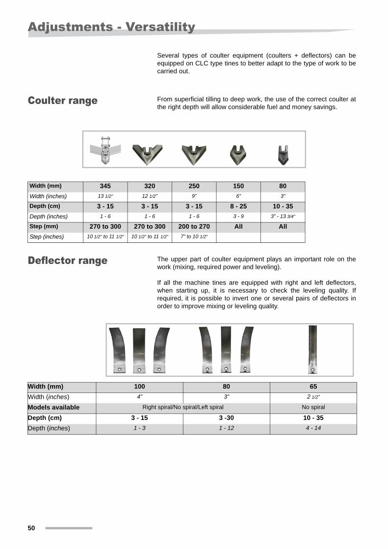
Adjustments - Versatility Several types of coulter equipment (coulters + deflectors) can be equipped on CLC type tines to better adapt to the type of work to be carried out.
Coulter range From superficial tilling to deep work, the use of the correct coulter at the right depth will allow considerable fuel and money savings.
Deflector range The upper part of coulter equipment plays an important role on the work (mixing, required power and leveling).
If all the machine tines are equipped with right and left deflectors, when starting up, it is necessary to check the leveling quality. If required, it is possible to invert one or several pairs of deflectors in order to improve mixing or leveling quality.
Width (mm) 345 320 250 150 80
Width (inches) 13 1/2” 12 1/2” 9” 6” 3”
Depth (cm) 3 - 15 3 - 15 3 - 15 8 - 25 10 - 35
Depth (inches) 1 - 6 1 - 6 1 - 6 3 - 9 3” - 13 3/4”
Step (mm) 270 to 300 270 to 300 200 to 270 All All
Step (inches) 10 1/2” to 11 1/2” 10 1/2” to 11 1/2” 7” to 10 1/2”
Width (mm) 100 80 65
Width (inches) 4” 3” 2 1/2”
Models available Right spiral/No spiral/Left spiral No spiral
Depth (cm) 3 - 15 3 -30 10 - 35
Depth (inches) 1 - 3 1 - 12 4 - 14
50
Adjustments
Adjustments
IMPORTANT NOTE Never turn the machine with the tool in the ground.
\ DANGER
Respect of safety instructions Failure to respect the safety instructions may cause serious injury or even death. Refer to Chapter Safety, page 5.
Never stand on the rollers even if they are placed on the ground.
\ WARNING
Keep at a safe distance when changing the settings.Always keep a safe distance from the machine when adjusting settings. Failure to follow this instruction could result in serious injury, even death. In particular, there is a risk that your legs could be crushed.
When making adjustments, always be sure to maintain three bearing points.
The machine parts may turn out to be slippery when wet. Be very careful not to fall when standing on machine parts.
51
Adjustments
IMPORTANT NOTE Never turn the machine with the tool in the ground.
Adjustment of the working depth
The working depth of the stubble tines is controlled by the rear roller and/or by the optional depth control wheels at the front of the machine.
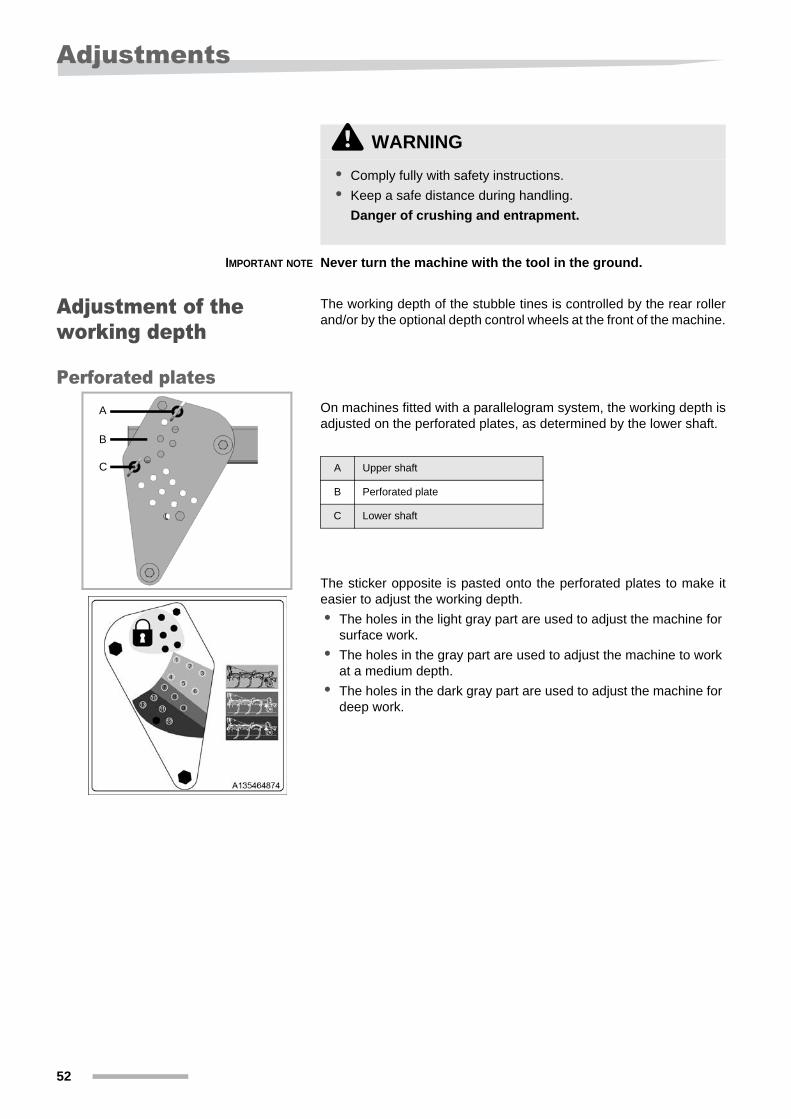
Perforated platesOn machines fitted with a parallelogram system, the working depth is adjusted on the perforated plates, as determined by the lower shaft.
The sticker opposite is pasted onto the perforated plates to make it easier to adjust the working depth.
• The holes in the light gray part are used to adjust the machine for surface work.
• The holes in the gray part are used to adjust the machine to work at a medium depth.
• The holes in the dark gray part are used to adjust the machine for deep work.
\ WARNING
• Comply fully with safety instructions.
• Keep a safe distance during handling.
Danger of crushing and entrapment.
A
B
C A Upper shaft
B Perforated plate
C Lower shaft
52
Adjustments
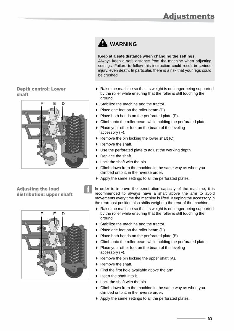
Depth control: Lower shaft
Raise the machine so that its weight is no longer being supported by the roller while ensuring that the roller is still touching the ground.
Stabilize the machine and the tractor.
Place one foot on the roller beam (D).
Place both hands on the perforated plate (E).
Climb onto the roller beam while holding the perforated plate.
Place your other foot on the beam of the leveling accessory (F).
Remove the pin locking the lower shaft (C).
Remove the shaft.
Use the perforated plate to adjust the working depth.
Replace the shaft.
Lock the shaft with the pin.
Climb down from the machine in the same way as when you climbed onto it, in the reverse order.
Apply the same settings to all the perforated plates.
Adjusting the load distribution: upper shaft
In order to improve the penetration capacity of the machine, it is recommended to always have a shaft above the arm to avoid movements every time the machine is lifted. Keeping the accessory in the rearmost position also shifts weight to the rear of the machine.
Raise the machine so that its weight is no longer being supported by the roller while ensuring that the roller is still touching the ground.
Stabilize the machine and the tractor.
Place one foot on the roller beam (D).
Place both hands on the perforated plate (E).
Climb onto the roller beam while holding the perforated plate.
Place your other foot on the beam of the leveling accessory (F).
Remove the pin locking the upper shaft (A).
Remove the shaft.
Find the first hole available above the arm.
Insert the shaft into it.
Lock the shaft with the pin.
Climb down from the machine in the same way as when you climbed onto it, in the reverse order.
Apply the same settings to all the perforated plates.
\ WARNING
Keep at a safe distance when changing the settings.Always keep a safe distance from the machine when adjusting settings. Failure to follow this instruction could result in serious injury, even death. In particular, there is a risk that your legs could be crushed.
DF E
DF E
53
Adjustments
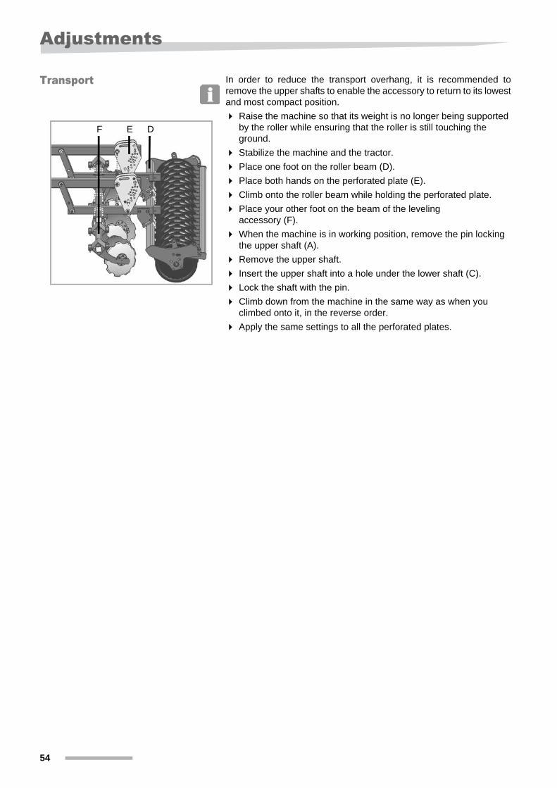
Transport In order to reduce the transport overhang, it is recommended to remove the upper shafts to enable the accessory to return to its lowest and most compact position.
Raise the machine so that its weight is no longer being supported by the roller while ensuring that the roller is still touching the ground.
Stabilize the machine and the tractor.
Place one foot on the roller beam (D).
Place both hands on the perforated plate (E).
Climb onto the roller beam while holding the perforated plate.
Place your other foot on the beam of the leveling accessory (F).
When the machine is in working position, remove the pin locking the upper shaft (A).
Remove the upper shaft.
Insert the upper shaft into a hole under the lower shaft (C).
Lock the shaft with the pin.
Climb down from the machine in the same way as when you climbed onto it, in the reverse order.
Apply the same settings to all the perforated plates.
DF E
54
Adjustments
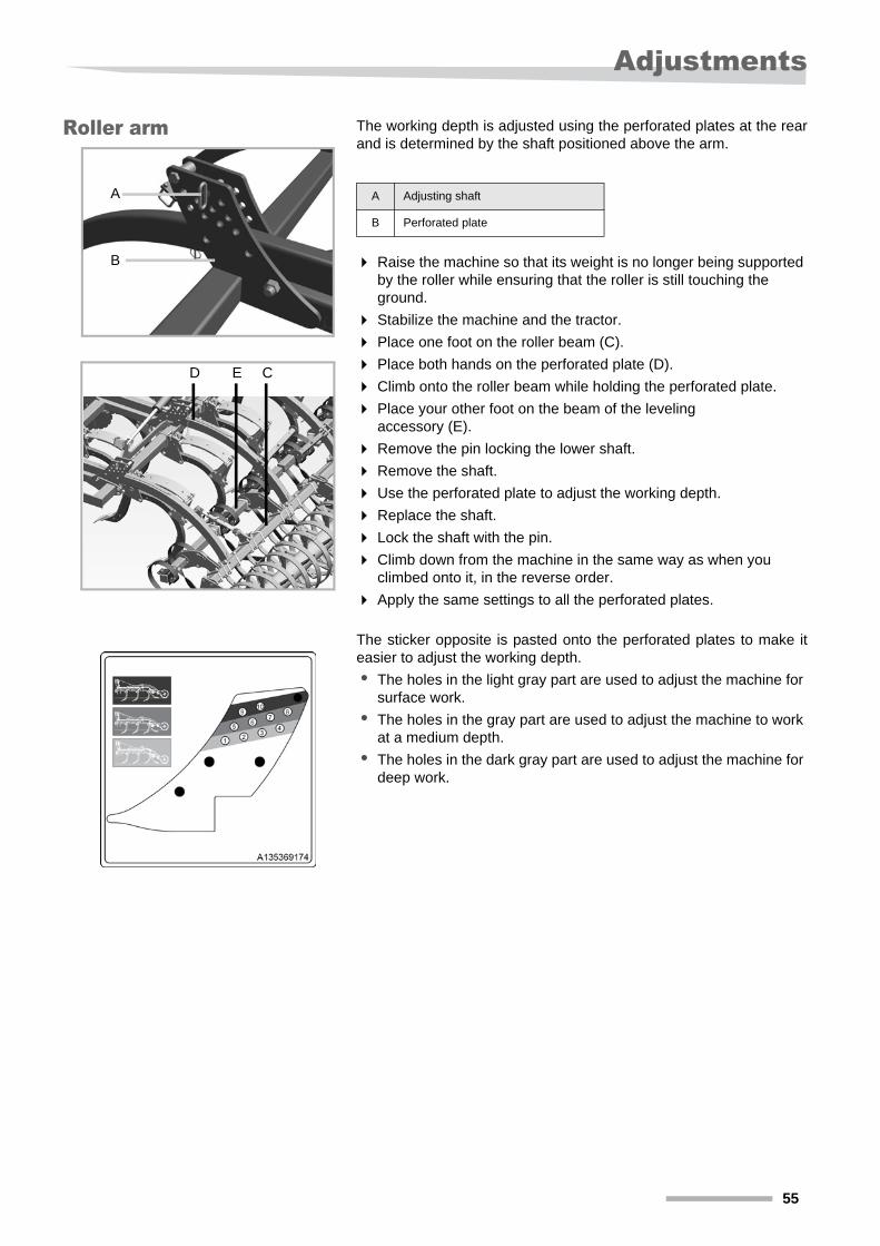
Roller arm The working depth is adjusted using the perforated plates at the rear and is determined by the shaft positioned above the arm.
Raise the machine so that its weight is no longer being supported by the roller while ensuring that the roller is still touching the ground.
Stabilize the machine and the tractor.
Place one foot on the roller beam (C).
Place both hands on the perforated plate (D).
Climb onto the roller beam while holding the perforated plate.
Place your other foot on the beam of the leveling accessory (E).
Remove the pin locking the lower shaft.
Remove the shaft.
Use the perforated plate to adjust the working depth.
Replace the shaft.
Lock the shaft with the pin.
Climb down from the machine in the same way as when you climbed onto it, in the reverse order.
Apply the same settings to all the perforated plates.
The sticker opposite is pasted onto the perforated plates to make it easier to adjust the working depth.
• The holes in the light gray part are used to adjust the machine for surface work.
• The holes in the gray part are used to adjust the machine to work at a medium depth.
• The holes in the dark gray part are used to adjust the machine for deep work.
A
B
CED
A Adjusting shaft
B Perforated plate
55
Adjustments
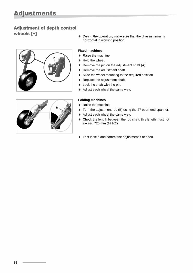
Adjustment of depth control wheels [+]
During the operation, make sure that the chassis remains horizontal in working position.
Fixed machines
Raise the machine.
Hold the wheel.
Remove the pin on the adjustment shaft (A).
Remove the adjustment shaft.
Slide the wheel mounting to the required position.
Replace the adjustment shaft.
Lock the shaft with the pin.
Adjust each wheel the same way.
Folding machines
Raise the machine.
Turn the adjustment rod (B) using the 27 open-end spanner.
Adjust each wheel the same way.
Check the length between the rod shaft; this length must not exceed 720 mm (28 1/2”).
Test in field and correct the adjustment if needed.
A
B
56
Adjustments
Adjustment of the rear accessories
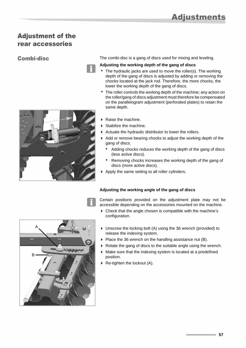
Combi-disc The combi-disc is a gang of discs used for mixing and leveling.
Adjusting the working depth of the gang of discs
• The hydraulic jacks are used to move the roller(s). The working depth of the gang of discs is adjusted by adding or removing the chocks located at the jack rod. Therefore, the more chocks, the lower the working depth of the gang of discs.
• The roller controls the working depth of the machine; any action on the roller/gang of discs adjustment must therefore be compensated on the parallelogram adjustment (perforated plates) to retain the same depth.
Raise the machine.
Stabilize the machine.
Actuate the hydraulic distributor to lower the rollers.
Add or remove bearing chocks to adjust the working depth of the gang of discs.
• Adding chocks reduces the working depth of the gang of discs (less active discs).
• Removing chocks increases the working depth of the gang of discs (more active discs).
Apply the same setting to all roller cylinders.
Adjusting the working angle of the gang of discs
Certain positions provided on the adjustment plate may not be accessible depending on the accessories mounted on the machine.
Check that the angle chosen is compatible with the machine’s configuration.
Unscrew the locking bolt (A) using the 36 wrench (provided) to release the indexing system.
Place the 36 wrench on the handling assistance nut (B).
Rotate the gang of discs to the suitable angle using the wrench.
Make sure that the indexing system is located at a predefined position.
Re-tighten the locknut (A).
A
B
57
Adjustments
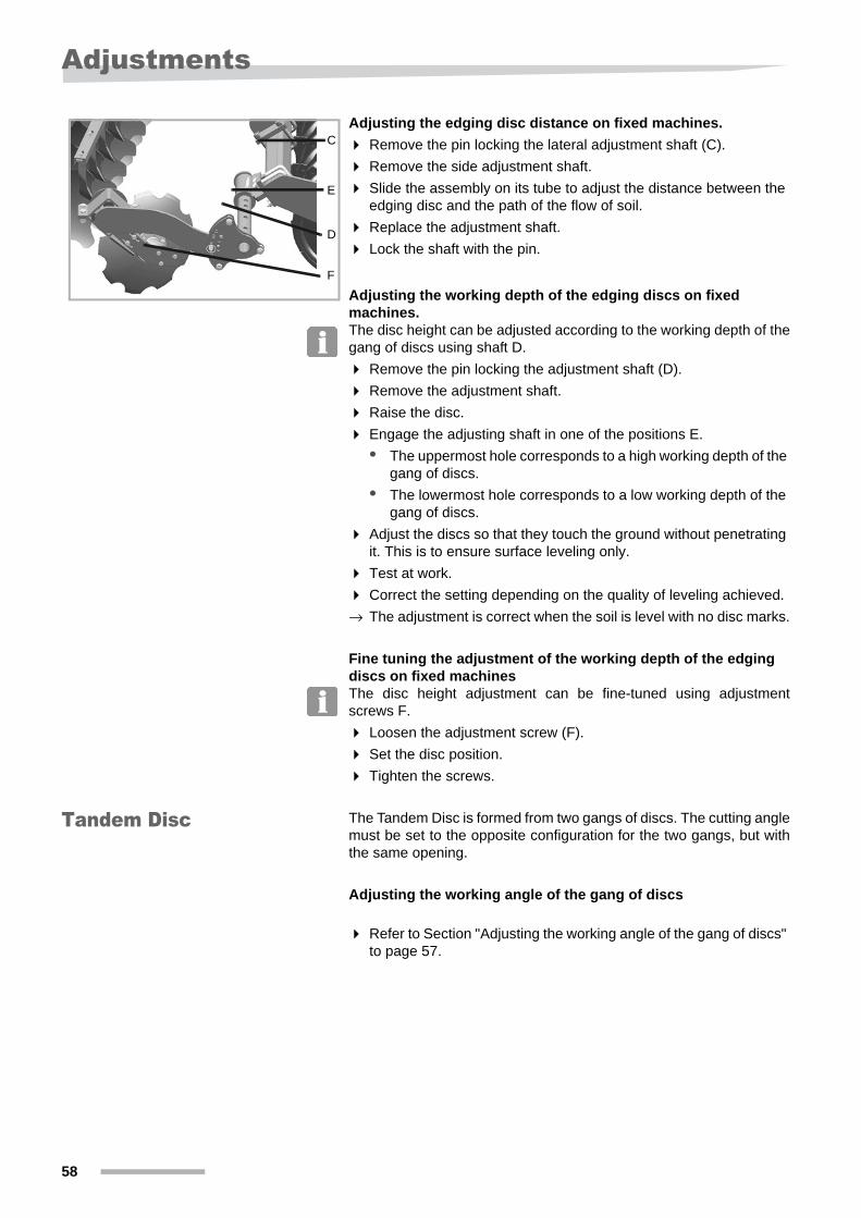
Adjusting the edging disc distance on fixed machines.
Remove the pin locking the lateral adjustment shaft (C).
Remove the side adjustment shaft.
Slide the assembly on its tube to adjust the distance between the edging disc and the path of the flow of soil.
Replace the adjustment shaft.
Lock the shaft with the pin.
Adjusting the working depth of the edging discs on fixed machines.The disc height can be adjusted according to the working depth of the gang of discs using shaft D.
Remove the pin locking the adjustment shaft (D).
Remove the adjustment shaft.
Raise the disc.
Engage the adjusting shaft in one of the positions E.
• The uppermost hole corresponds to a high working depth of the gang of discs.
• The lowermost hole corresponds to a low working depth of the gang of discs.
Adjust the discs so that they touch the ground without penetrating it. This is to ensure surface leveling only.
Test at work.
Correct the setting depending on the quality of leveling achieved.
→ The adjustment is correct when the soil is level with no disc marks.
Fine tuning the adjustment of the working depth of the edging discs on fixed machinesThe disc height adjustment can be fine-tuned using adjustment screws F.
Loosen the adjustment screw (F).
Set the disc position.
Tighten the screws.
Tandem Disc The Tandem Disc is formed from two gangs of discs. The cutting angle must be set to the opposite configuration for the two gangs, but with the same opening.
Adjusting the working angle of the gang of discs
Refer to Section "Adjusting the working angle of the gang of discs" to page 57.
C
D
E
F
58
Adjustments
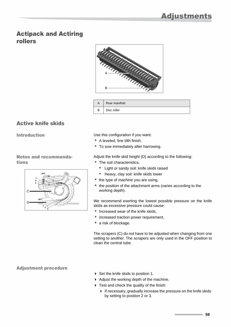
Actipack and Actiring rollers
Active knife skids
Introduction Use this configuration if you want:
• A leveled, fine tilth finish.
• To sow immediately after harrowing.
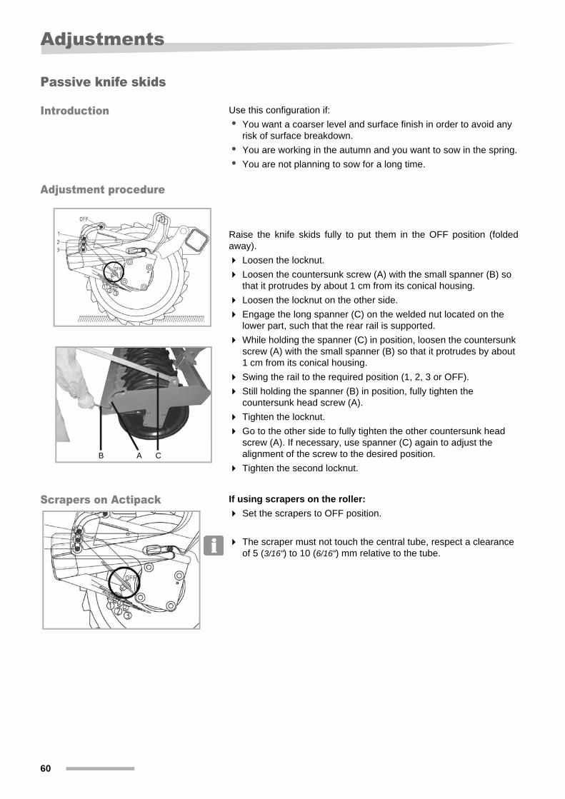
Notes and recommenda-tions
Adjust the knife skid height (D) according to the following:
• The soil characteristics,
• Light or sandy soil: knife skids raised
• Heavy, clay soil: knife skids lower
• the type of machine you are using,
• the position of the attachment arms (varies according to the working depth).
We recommend exerting the lowest possible pressure on the knife skids as excessive pressure could cause:
• Increased wear of the knife skids,
• increased traction power requirement,
• a risk of blockage.
The scrapers (C) do not have to be adjusted when changing from one setting to another. The scrapers are only used in the OFF position to clean the central tube.
Adjustment procedure Set the knife skids to position 1.
Adjust the working depth of the machine.
Test and check the quality of the finish:
If necessary, gradually increase the pressure on the knife skids by setting to position 2 or 3.
A Rear manifold
B Disc roller
A
B
C
D
59
Adjustments
Passive knife skids
Introduction Use this configuration if:
• You want a coarser level and surface finish in order to avoid any risk of surface breakdown.
• You are working in the autumn and you want to sow in the spring.
• You are not planning to sow for a long time.
Adjustment procedure
Raise the knife skids fully to put them in the OFF position (folded away).
Loosen the locknut.
Loosen the countersunk screw (A) with the small spanner (B) so that it protrudes by about 1 cm from its conical housing.
Loosen the locknut on the other side.
Engage the long spanner (C) on the welded nut located on the lower part, such that the rear rail is supported.
While holding the spanner (C) in position, loosen the countersunk screw (A) with the small spanner (B) so that it protrudes by about 1 cm from its conical housing.
Swing the rail to the required position (1, 2, 3 or OFF).
Still holding the spanner (B) in position, fully tighten the countersunk head screw (A).
Tighten the locknut.
Go to the other side to fully tighten the other countersunk head screw (A). If necessary, use spanner (C) again to adjust the alignment of the screw to the desired position.
Tighten the second locknut.
Scrapers on Actipack If using scrapers on the roller:
Set the scrapers to OFF position.
The scraper must not touch the central tube, respect a clearance of 5 (3/16”) to 10 (6/16”) mm relative to the tube.
AB C
60
Adjustments
Actiflex roller
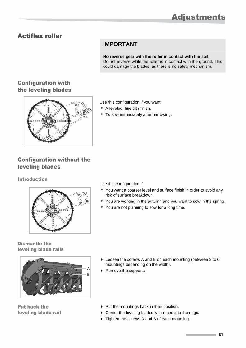
Configuration with the leveling blades
Use this configuration if you want:
• A leveled, fine tilth finish.
• To sow immediately after harrowing.
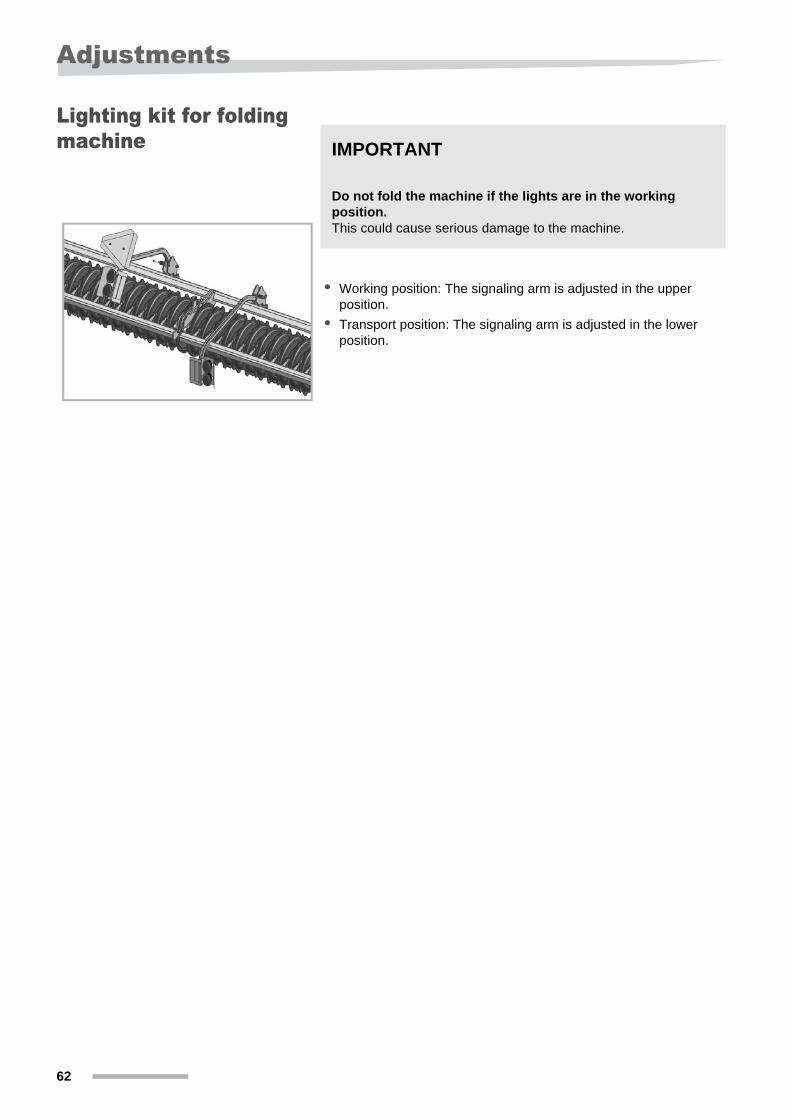
Configuration without the leveling blades
IntroductionUse this configuration if:
• You want a coarser level and surface finish in order to avoid any risk of surface breakdown.
• You are working in the autumn and you want to sow in the spring.
• You are not planning to sow for a long time.
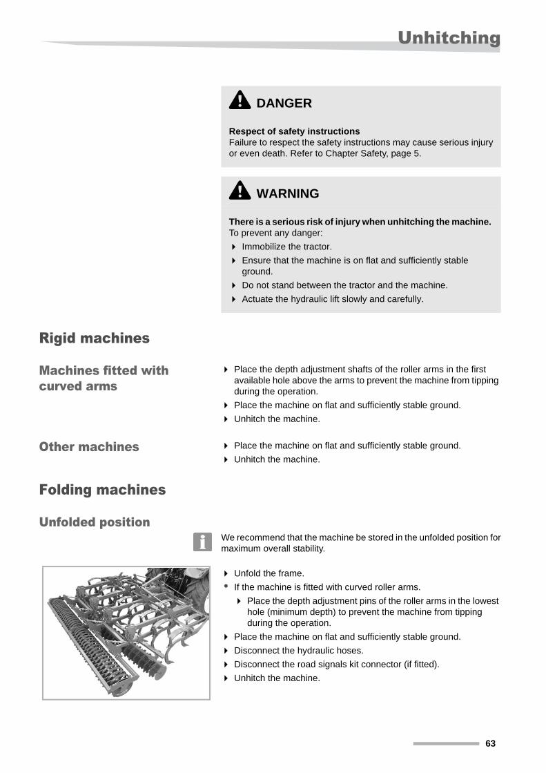
Dismantle the leveling blade rails
Loosen the screws A and B on each mounting (between 3 to 6 mountings depending on the width).
Remove the supports
Put back the leveling blade rail
Put the mountings back in their position.
Center the leveling blades with respect to the rings.
Tighten the screws A and B of each mounting.
IMPORTANT
No reverse gear with the roller in contact with the soil.Do not reverse while the roller is in contact with the ground. This could damage the blades, as there is no safety mechanism.
A
B
61
Adjustments
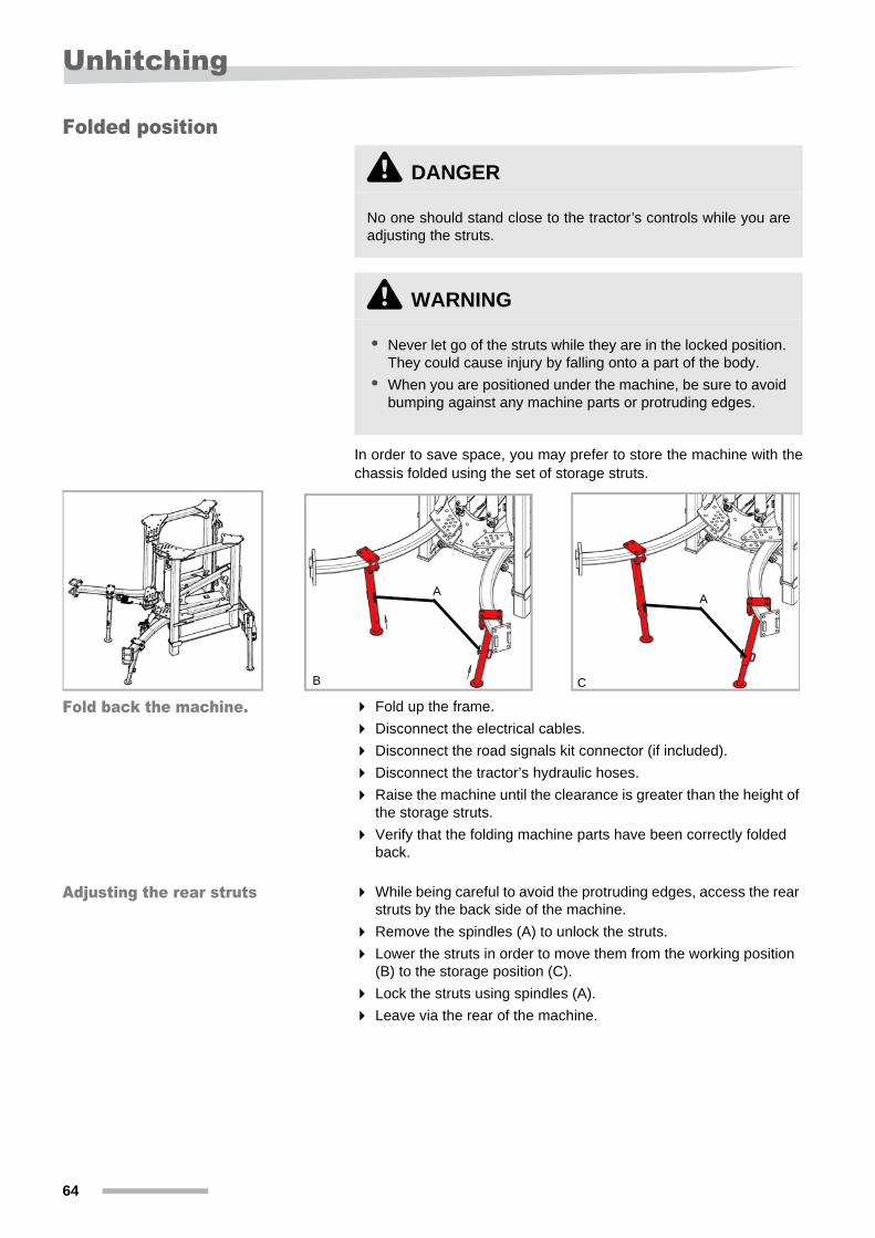
Lighting kit for folding machine
• Working position: The signaling arm is adjusted in the upper position.
• Transport position: The signaling arm is adjusted in the lower position.
IMPORTANT
Do not fold the machine if the lights are in the working position.This could cause serious damage to the machine.
62
Unhitching
Unhitching
Rigid machines
Machines fitted with curved arms
Place the depth adjustment shafts of the roller arms in the first available hole above the arms to prevent the machine from tipping during the operation.
Place the machine on flat and sufficiently stable ground.
Unhitch the machine.
Other machines Place the machine on flat and sufficiently stable ground.
Unhitch the machine.
Folding machines
Unfolded positionWe recommend that the machine be stored in the unfolded position for maximum overall stability.
Unfold the frame.
• If the machine is fitted with curved roller arms.
Place the depth adjustment pins of the roller arms in the lowest hole (minimum depth) to prevent the machine from tipping during the operation.
Place the machine on flat and sufficiently stable ground.
Disconnect the hydraulic hoses.
Disconnect the road signals kit connector (if fitted).
Unhitch the machine.
\ DANGER
Respect of safety instructions Failure to respect the safety instructions may cause serious injury or even death. Refer to Chapter Safety, page 5.
\ WARNING
There is a serious risk of injury when unhitching the machine. To prevent any danger:
Immobilize the tractor.
Ensure that the machine is on flat and sufficiently stable ground.
Do not stand between the tractor and the machine.
Actuate the hydraulic lift slowly and carefully.
63
Unhitching
Folded position
In order to save space, you may prefer to store the machine with the chassis folded using the set of storage struts.
Fold back the machine. Fold up the frame.
Disconnect the electrical cables.
Disconnect the road signals kit connector (if included).
Disconnect the tractor’s hydraulic hoses.
Raise the machine until the clearance is greater than the height of the storage struts.
Verify that the folding machine parts have been correctly folded back.
Adjusting the rear struts While being careful to avoid the protruding edges, access the rear struts by the back side of the machine.
Remove the spindles (A) to unlock the struts.
Lower the struts in order to move them from the working position (B) to the storage position (C).
Lock the struts using spindles (A).
Leave via the rear of the machine.
\ DANGER
No one should stand close to the tractor’s controls while you are adjusting the struts.
\ WARNING
• Never let go of the struts while they are in the locked position. They could cause injury by falling onto a part of the body.
• When you are positioned under the machine, be sure to avoid bumping against any machine parts or protruding edges.
AA
B C
64
Unhitching
Adjust the front struts Lower the machine onto a stable surface so that its weight is being supported by the rear struts and that the tension applied on the upper link is released.
Unhitch the upper link.
Adjust the tractor lifting height in such a way to allow placing the front struts into the storage position.
Remove the spindles (A) to unlock the struts.
Lower the struts in order to move them from the working position (B) to the storage position (C).
Lock the struts using spindles (A).
Store the machine Lower the machine to a point where the struts are positioned on a stable and regular surface.
Ensure that there are no obstacles or uneven surface under the support legs.
Ensure that the machine is positioned parallel to the ground and the struts are not digging into the floor.
Unhitch the machine.
65

Maintenance
MaintenanceCleaning
The equipment may be cleaned using a high pressure cleaner.
Move the water jet further away when cleaning the bearings to avoid damaging the seals and roller bearings.
Protect the cylinder rods.
Maintenance To ensure that the machine has a long service life, we recommend that a protective coating of oil is applied at the end of each season. Use only a suitable, biodegradable oil such as rape seed oil.
Storage To keep your machine in good condition during storage:
Clean it.
Lubricate the various points listed in the “Maintenance” section.
Store your machine on a flat, stable surface.
Machines stored in unfolded position: grease the cylinder rods before you use the machine.
Check the tire pressure.
IMPORTANT
Do not clean using a rotating nozzleNever use a high pressure cleaner with a rotating nozzle to clean your machine. This could damage the machine.
IMPORTANT
For wheels with rubber tires: Cover the tires before applying oil. Oil can damage tires.
Model TireRecommended
pressure
Depth control wheels
6.00 - 96 bar
(87 psi)
Depth control wheels
10/80 - 123.9 bar (57 psi)
66
Maintenance
MaintenanceSafety instructions
Specific safety instructions
\ DANGER
Conditions necessary for maintenance work.Carry out maintenance work only if you have the necessary knowledge and tools at your disposal. A lack of knowledge or inappropriate tools may lead to accidents.
Prevent any unintentional movement of the machineCarry out repairs or maintenance or eliminate malfunctions with the machine hitched only when:
• the engine is switched off,
• the contact key has been removed,
• the electronic control system has been deactivated.
An unexpected movement of the machine could cause serious injury.
\ WARNING
Use original replacement partsUse only original replacement parts for safety-related components. Only parts of the appropriate dimensions, strength and material quality should be used. If parts other than original replacement parts are fitted, the warranty is void.
Do not use pneumatic grease pumpsWhen lubricating bearing housings, do not use pneumatic grease pumps under any circumstances. Their high pressure would damage the bearings.
67

Maintenance
Protection measures when handling oils and lubricants
Additives mixed with oils and lubricants can be harmful to your health. Since regulations do not require manufacturers to identify these hazards, it is essential that you follow the advice below:
Collect and dispose of used oil.
In the event of wounds to the skin caused by oil or lubricants, contact a doctor immediately.
\ DANGER
Avoid contact with the skinAvoid all skin contact with these products. Contact with the skin may cause skin damage.
Protect your skinProtect your skin when handling oils or lubricants by applying a protective cream on the skin or by wearing oil and lubricant-proof gloves. Oils may cause health problems.
Do not use the oils to clean your handsNever use oil or lubricants to clean your hands. Swarf in such liquids can also cause injury.
Do not wear clothing contaminated with oilRemove garments heavily soiled with oil as quickly as possible. Oils may cause health problems.
68
Maintenance
General These notes refer to routine maintenance work. For any maintenance work, the machine must be configured and locked in its working position. If the transport position is required for any maintenance work, refer to the maintenance instructions and read the relevant information.
RECOMMENDATIONS Work carried out with the grease pumpLubricate with two squeezes of the grease pump If you feel resistance during the second squeeze, do not proceed further. Excess grease will open seals. Dust and dirt can penetrate bearings and cause premature wear.
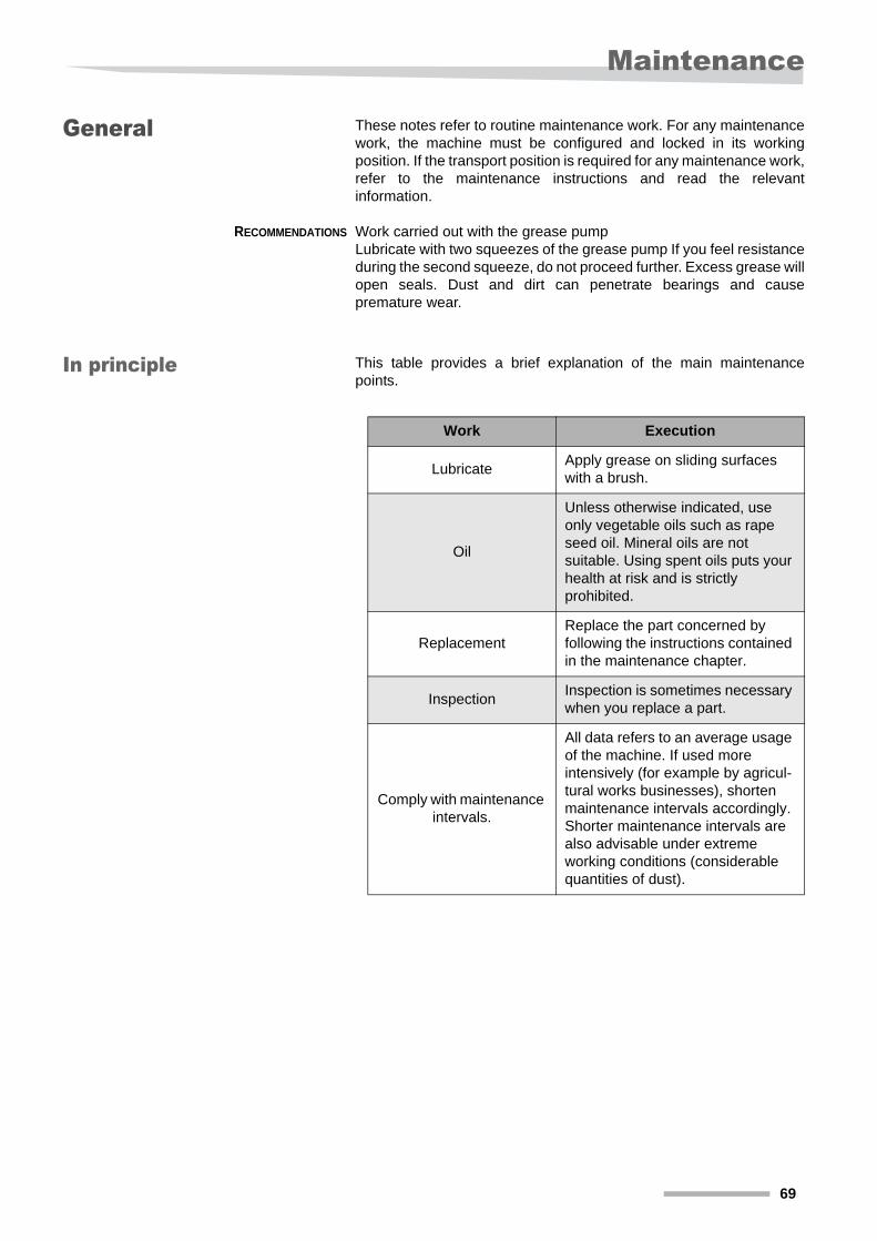
In principle This table provides a brief explanation of the main maintenance points.
Work Execution
LubricateApply grease on sliding surfaces with a brush.
Oil
Unless otherwise indicated, use only vegetable oils such as rape seed oil. Mineral oils are not suitable. Using spent oils puts your health at risk and is strictly prohibited.
Replacement Replace the part concerned by following the instructions contained in the maintenance chapter.
InspectionInspection is sometimes necessary when you replace a part.
Comply with maintenance intervals.
All data refers to an average usage of the machine. If used more intensively (for example by agricul-tural works businesses), shorten maintenance intervals accordingly. Shorter maintenance intervals are also advisable under extreme working conditions (considerable quantities of dust).
69
Maintenance
Greasing
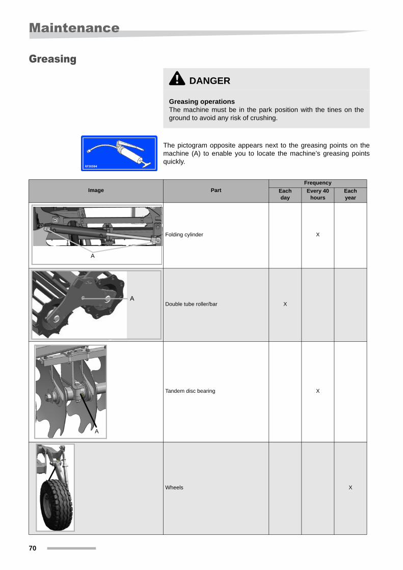
The pictogram opposite appears next to the greasing points on the machine (A) to enable you to locate the machine’s greasing points quickly.
\ DANGER
Greasing operationsThe machine must be in the park position with the tines on the ground to avoid any risk of crushing.
Image PartFrequency
Each day
Every 40 hours
Each year
Folding cylinder X
Double tube roller/bar X
Tandem disc bearing X
Wheels X
A
A
A
A
70
Maintenance
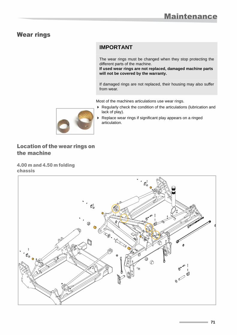
Wear rings
Most of the machines articulations use wear rings.
Regularly check the condition of the articulations (lubrication and lack of play).
Replace wear rings if significant play appears on a ringed articulation.
Location of the wear rings on the machine
4.00 m and 4.50 m folding chassis
IMPORTANT
The wear rings must be changed when they stop protecting the different parts of the machine.If used wear rings are not replaced, damaged machine parts will not be covered by the warranty.
If damaged rings are not replaced, their housing may also suffer from wear.
71
Maintenance
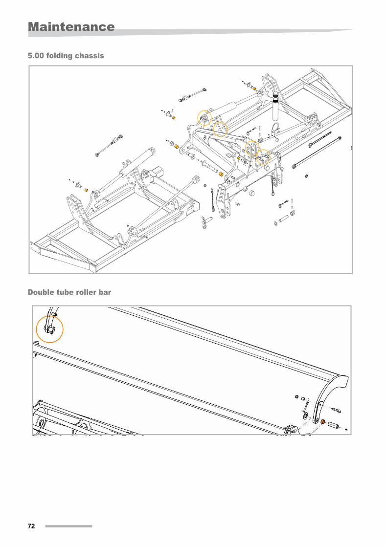
5.00 folding chassis
Double tube roller bar
72
Maintenance
Inspection
Screwed assemblies Regularly check wheel nuts for tightness and the hub clearance adjustment.
All the bolts must be tightened:
• After the initial period of use.
• According to the frequency of use.
• In any event, at least once a season.
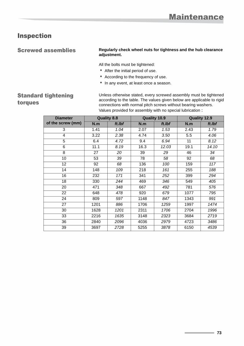
Standard tightening torques
Unless otherwise stated, every screwed assembly must be tightened according to the table. The values given below are applicable to rigid connections with normal pitch screws without bearing washers. Values provided for assembly with no special lubrication :
Diameter of the screw (mm)
Quality 8.8 Quality 10.9 Quality 12.9
N.m ft.lbf N.m ft.lbf N.m ft.lbf3 1.41 1.04 2.07 1.53 2.43 1.794 3.22 2.38 4.74 3.50 5.5 4.065 6.4 4.72 9.4 6.94 11 8.126 11.1 8.19 16.3 12.03 19.1 14.108 27 20 39 29 46 3410 53 39 78 58 92 6812 92 68 136 100 159 11714 148 109 218 161 255 18816 232 171 341 252 399 29418 330 244 469 346 549 40520 471 348 667 492 781 57622 648 478 920 679 1077 79524 809 597 1148 847 1343 99127 1201 886 1706 1259 1997 147430 1628 1201 2311 1706 2704 199633 2216 1635 3148 2323 3684 271936 2840 2096 4036 2979 4723 348639 3697 2728 5255 3878 6150 4539
73
Maintenance
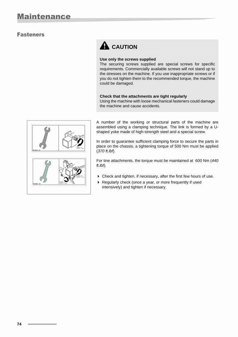
Fasteners
A number of the working or structural parts of the machine are assembled using a clamping technique. The link is formed by a U-shaped yoke made of high-strength steel and a special screw.
In order to guarantee sufficient clamping force to secure the parts in place on the chassis, a tightening torque of 500 Nm must be applied (370 ft.lbf).
For tine attachments, the torque must be maintained at 600 Nm (440 ft.lbf).
Check and tighten, if necessary, after the first few hours of use.
Regularly check (once a year, or more frequently if used intensively) and tighten if necessary.
\ CAUTION
Use only the screws suppliedThe securing screws supplied are special screws for specific requirements. Commercially available screws will not stand up to the stresses on the machine. If you use inappropriate screws or if you do not tighten them to the recommended torque, the machine could be damaged.
Check that the attachments are tight regularlyUsing the machine with loose mechanical fasteners could damage the machine and cause accidents.
74
Maintenance
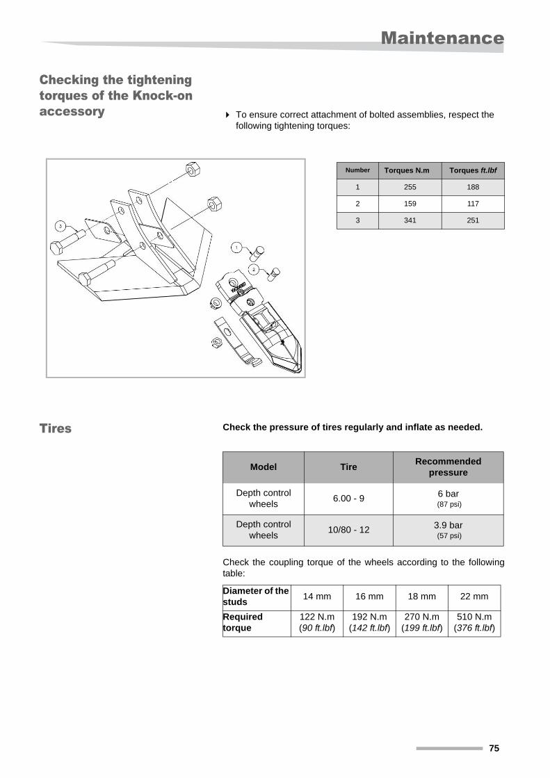
Checking the tightening torques of the Knock-on accessory To ensure correct attachment of bolted assemblies, respect the
following tightening torques:
Tires Check the pressure of tires regularly and inflate as needed.
Check the coupling torque of the wheels according to the following table:
Number Torques N.m Torques ft.lbf
1 255 188
2 159 117
3 341 251
Model TireRecommended
pressure
Depth control wheels
6.00 - 9 6 bar (87 psi)
Depth control wheels
10/80 - 12 3.9 bar (57 psi)
Diameter of the studs
14 mm 16 mm 18 mm 22 mm
Required torque
122 N.m(90 ft.lbf)
192 N.m(142 ft.lbf)
270 N.m(199 ft.lbf)
510 N.m(376 ft.lbf)
75
Maintenance
Replacing the tines
Replace the tines when they are worn. Depending on the equipment, they may be:
• Rigid tines fitted with a bolt safety system.
• Tines with blade spring fitted with a Non-stop safety system.
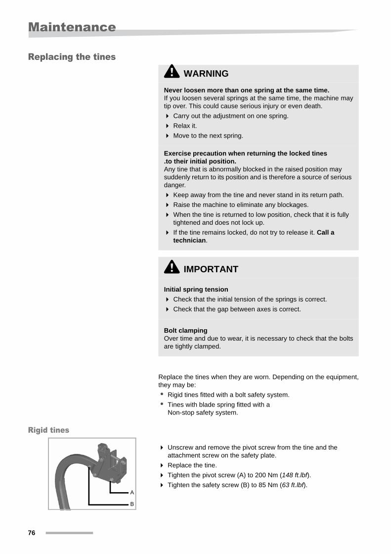
Rigid tines
Unscrew and remove the pivot screw from the tine and the attachment screw on the safety plate.
Replace the tine.
Tighten the pivot screw (A) to 200 Nm (148 ft.lbf). Tighten the safety screw (B) to 85 Nm (63 ft.lbf).
\ WARNING
Never loosen more than one spring at the same time.If you loosen several springs at the same time, the machine may tip over. This could cause serious injury or even death.
Carry out the adjustment on one spring.
Relax it.
Move to the next spring.
Exercise precaution when returning the locked tines .to their initial position.Any tine that is abnormally blocked in the raised position may suddenly return to its position and is therefore a source of serious danger.
Keep away from the tine and never stand in its return path.
Raise the machine to eliminate any blockages.
When the tine is returned to low position, check that it is fully tightened and does not lock up.
If the tine remains locked, do not try to release it. Call a technician.
\ IMPORTANT
Initial spring tension
Check that the initial tension of the springs is correct.
Check that the gap between axes is correct.
Bolt clampingOver time and due to wear, it is necessary to check that the bolts are tightly clamped.
A
B
76
Maintenance
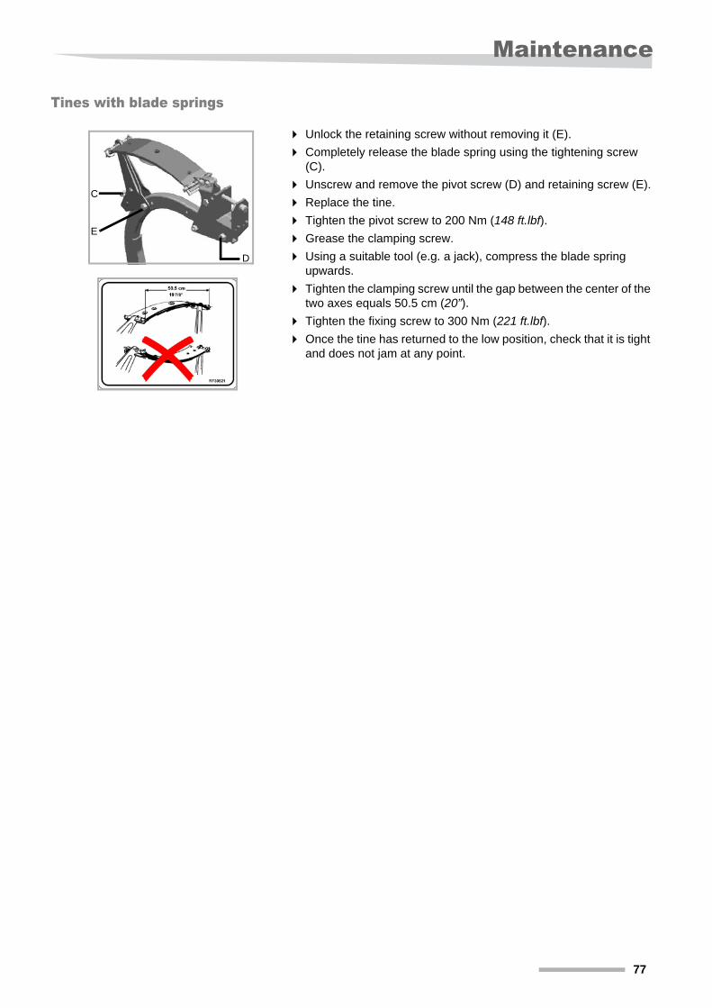
Tines with blade springs
Unlock the retaining screw without removing it (E).
Completely release the blade spring using the tightening screw (C).
Unscrew and remove the pivot screw (D) and retaining screw (E).
Replace the tine.
Tighten the pivot screw to 200 Nm (148 ft.lbf). Grease the clamping screw.
Using a suitable tool (e.g. a jack), compress the blade spring upwards.
Tighten the clamping screw until the gap between the center of the two axes equals 50.5 cm (20”).
Tighten the fixing screw to 300 Nm (221 ft.lbf). Once the tine has returned to the low position, check that it is tight
and does not jam at any point.
C
E
D
77
Maintenance
Coulter wear
Regularly check the wear of the coulters, tine protection and deflectors.
Replace the coulters, tine protection and deflectors before they are too worn.
Knock-on coulters
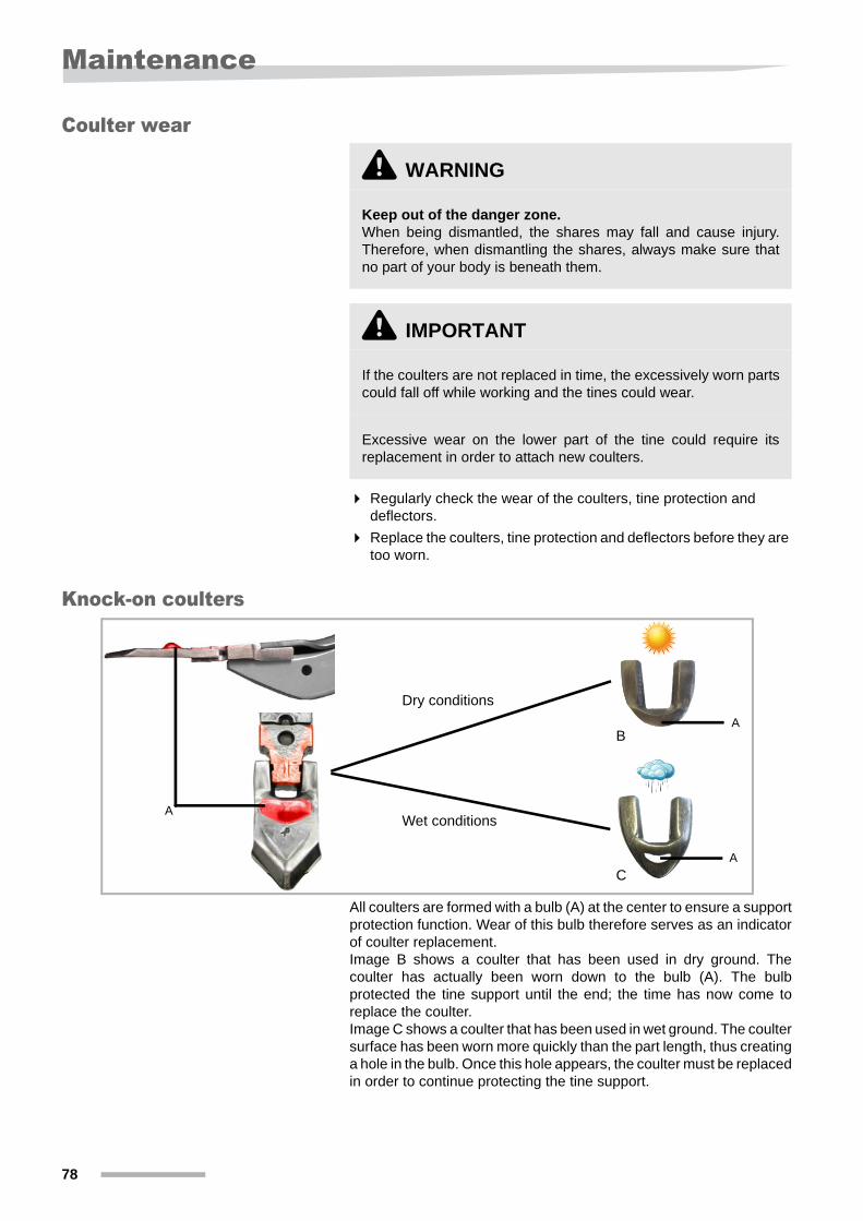
All coulters are formed with a bulb (A) at the center to ensure a support protection function. Wear of this bulb therefore serves as an indicator of coulter replacement.Image B shows a coulter that has been used in dry ground. The coulter has actually been worn down to the bulb (A). The bulb protected the tine support until the end; the time has now come to replace the coulter.Image C shows a coulter that has been used in wet ground. The coulter surface has been worn more quickly than the part length, thus creating a hole in the bulb. Once this hole appears, the coulter must be replaced in order to continue protecting the tine support.
\ WARNING
Keep out of the danger zone.When being dismantled, the shares may fall and cause injury. Therefore, when dismantling the shares, always make sure that no part of your body is beneath them.
\ IMPORTANT
If the coulters are not replaced in time, the excessively worn parts could fall off while working and the tines could wear.
Excessive wear on the lower part of the tine could require its replacement in order to attach new coulters.
A
Dry conditions
Wet conditions
B
C
A
A
78
Maintenance
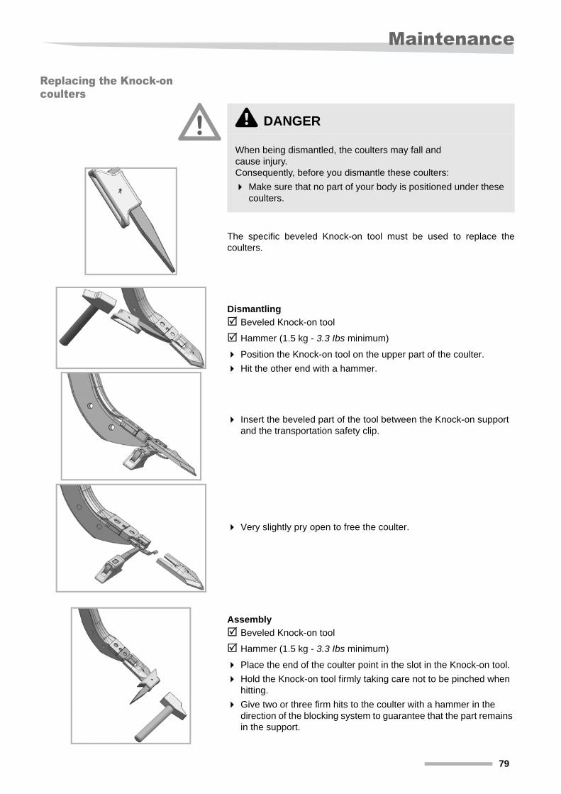
Replacing the Knock-on coulters
The specific beveled Knock-on tool must be used to replace the coulters.
Dismantling
Beveled Knock-on tool
Hammer (1.5 kg - 3.3 Ibs minimum)
Position the Knock-on tool on the upper part of the coulter.
Hit the other end with a hammer.
Insert the beveled part of the tool between the Knock-on support and the transportation safety clip.
Very slightly pry open to free the coulter.
Assembly
Beveled Knock-on tool
Hammer (1.5 kg - 3.3 Ibs minimum)
Place the end of the coulter point in the slot in the Knock-on tool.
Hold the Knock-on tool firmly taking care not to be pinched when hitting.
Give two or three firm hits to the coulter with a hammer in the direction of the blocking system to guarantee that the part remains in the support.
\ DANGER
When being dismantled, the coulters may fall and cause injury. Consequently, before you dismantle these coulters:
Make sure that no part of your body is positioned under these coulters.
79
Maintenance
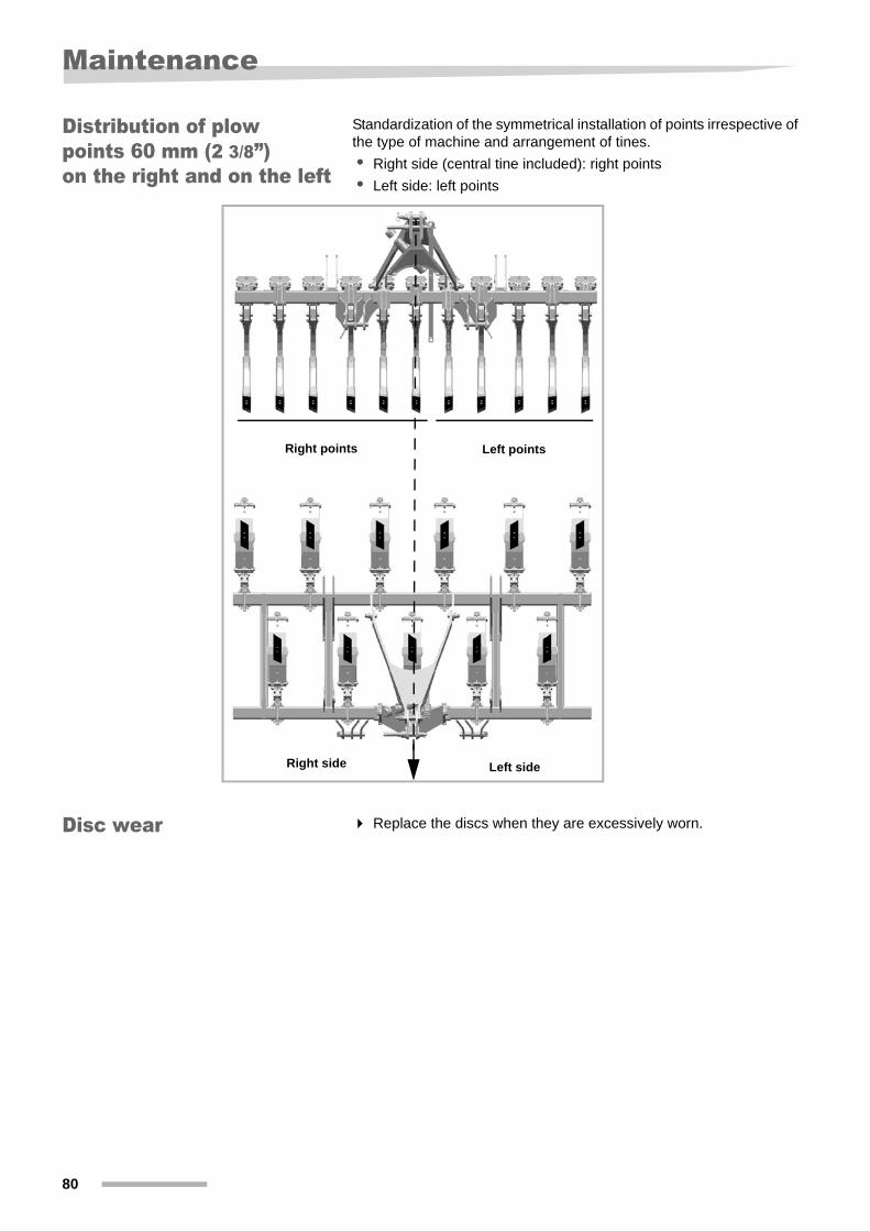
Distribution of plow points 60 mm (2 3/8”) on the right and on the left
Standardization of the symmetrical installation of points irrespective of the type of machine and arrangement of tines.
• Right side (central tine included): right points
• Left side: left points
Disc wear Replace the discs when they are excessively worn.
Right points Left points
Right side Left side
80
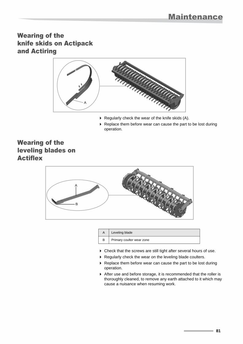
Maintenance
Wearing of the knife skids on Actipack and Actiring
Regularly check the wear of the knife skids (A).
Replace them before wear can cause the part to be lost during operation.
Wearing of the leveling blades on Actiflex
Check that the screws are still tight after several hours of use.
Regularly check the wear on the leveling blade coulters.
Replace them before wear can cause the part to be lost during operation.
After use and before storage, it is recommended that the roller is thoroughly cleaned, to remove any earth attached to it which may cause a nuisance when resuming work.
Hydraulic diagrams
A
A
B
A Leveling blade
B Primary coulter wear zone
81
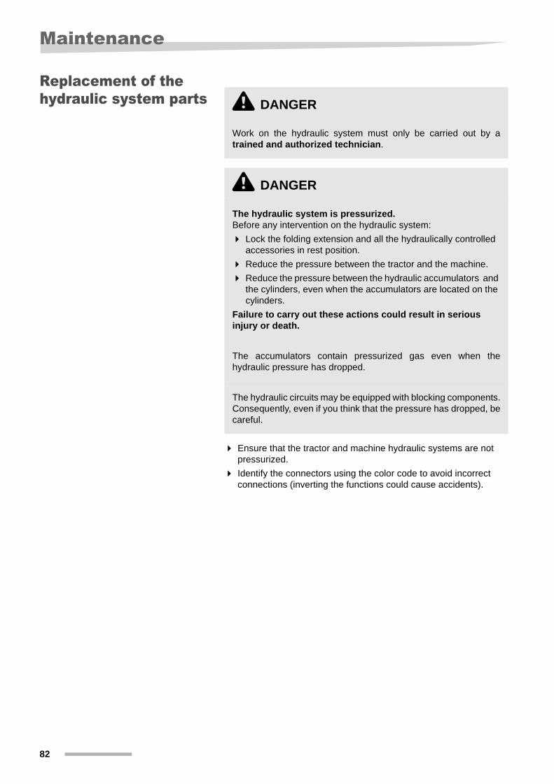
Maintenance
Replacement of the hydraulic system parts
Ensure that the tractor and machine hydraulic systems are not pressurized.
Identify the connectors using the color code to avoid incorrect connections (inverting the functions could cause accidents).
\ DANGER
Work on the hydraulic system must only be carried out by a trained and authorized technician.
\ DANGER
The hydraulic system is pressurized.Before any intervention on the hydraulic system:
Lock the folding extension and all the hydraulically controlled accessories in rest position.
Reduce the pressure between the tractor and the machine.
Reduce the pressure between the hydraulic accumulators and the cylinders, even when the accumulators are located on the cylinders.
Failure to carry out these actions could result in serious injury or death.
The accumulators contain pressurized gas even when the hydraulic pressure has dropped.
The hydraulic circuits may be equipped with blocking components. Consequently, even if you think that the pressure has dropped, be careful.
82
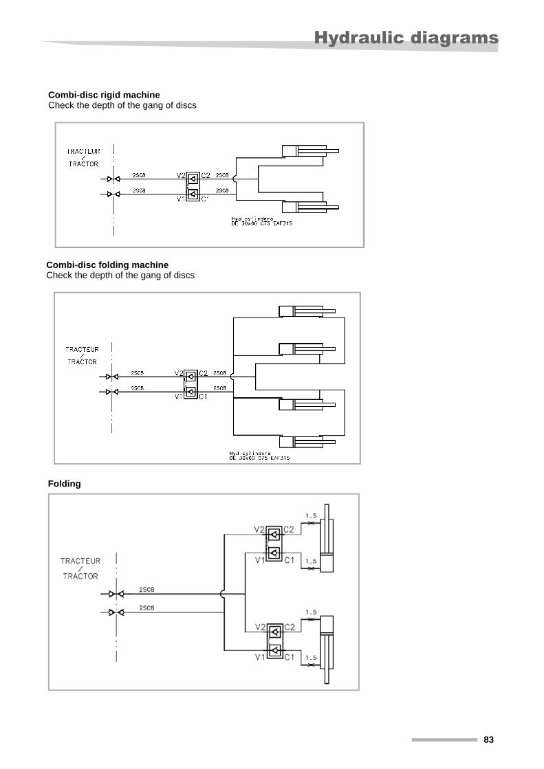
Hydraulic diagrams
Hydraulic diagrams
Combi-disc rigid machineCheck the depth of the gang of discs
Combi-disc folding machineCheck the depth of the gang of discs
Folding
83

Warranty
Warranty On delivery of the tool, check that all accessories are present and that no damage has occurred during transport. Any claims must be made to us in writing within 6 days.
The warranty will apply only if the conditions appearing on the delivery contract have been met by the buyer.
The warranty cannot apply if the machine:
• has been repaired by the customer without the dealer’s approval,
• has been modified by fitting non-original parts.
84
Scrapping the machine
Scrapping the machine
At the end of the machine’s life, it must be scrapped in accordance with environmental rules. Follow the appropriate instructions when disposing of the machine.
Metal parts All metal machine components can be recycled as scrap.
Tires Tires can be taken to a tire recycling center.
Hydraulic fluid Collect hydraulic fluid in clean, sealed containers designed for this purpose. Avoid using food containers or drink bottles.
Take hydraulic fluid and hoses to an appropriate recycling center.
Do not spread on the ground or pour into sewers used grease or other substances such as motor oil, hydraulic oil, coolant fluid, brake fluid, fuel, etc.
85

Index
86
Index
CCoulter range 50
DDeflector range 50Deflectors 30
MManager 6
PPanels 34Pictograms 4Plow point 29, 30
SSafety 5
General recommendations 18Hitching 19Hydraulic system 25Maintenance 23Use 21
Safety rules 18Screwed assemblies 73Signaling 34Standard equipment 31Symbols 4
TTechnical specifications 31Tightening torques 73Tire pressure 75Transport 20
UUser safety 5
WWheels with rubber tires 66