Embed Size (px)
Citation preview

4
Business Process Modeling Languages: Sorting Throughthe Alphabet Soup
HAFEDH MILI, GUY TREMBLAY, and GUITTA BOU JAOUDE
LATECE Laboratory, Universite du Quebec a Montreal
ERIC LEFEBVRE
Ecole de Technologie Superieure, Montreal
LAMIA ELABED
Institut Superieur de Gestion, Tunis
and
GHIZLANE EL BOUSSAIDI
LATECE Laboratory, Universite du Quebec a Montreal
Requirements capture is arguably the most important step in software engineering, and yet the most dif-ficult and the least formalized one [Phalp and Shepperd 2000]. Enterprises build information systems tosupport their business processes. Software engineering research has typically focused on the developmentprocess, starting with user requirements—if that—with business modeling often confused with software sys-tem modeling [Isoda 2001]. Researchers and practitioners in management information systems have longrecognized that understanding the business processes that an information system must support is key toeliciting the needs of its users (see e.g., Eriksson and Penker 2000]), but lacked the tools to model such busi-ness processes or to relate such models to software requirements. Researchers and practitioners in businessadministration have long been interested in modeling the processes of organizations for the purposes of un-derstanding, analyzing, and improving such processes [Hammer and Champy 1993], but their models wereoften too coarse to be of use to software engineers. The advent of ecommerce and workflow management sys-tems, among other things, has led to a convergence of interests and tools, within the broad IT community, formodeling and enabling business processes. In this article we present an overview of business process model-ing languages. We first propose a categorization of the various languages and then describe representativelanguages from each family.
Categories and Subject Descriptors: D.3.2 [Programming Languages]: Language Classifications; D.3.3[Programming Languages]: Language Constructs and Features; D.2.1 [Software Engineering]: Re-quirements Specifications; D.2.2 [Software Engineering]: Design Tools and Techniques
Authors’ addresses: H. Mili, G. Tremblay, G. Bou Jaoude, and G. El Boussaidi, Laboratoire de Recherches enTechnologies du Commerce Electronique (LATECE), Faculte des Sciences, Universite du Quebec a Montreal,B.P 8888, succursale Centre-Ville, Montreal (Quebec) H3C 3P8, Canada; email: [email protected];E. Lefebvre, Departement de genie logiciel et des TI, Ecole de technologie superieure, Montreal, Canada;L. Elabed, Institut Superieur de Gestion, Tunis, Tunisia.Permission to make digital or hard copies of part or all of this work for personal or classroom use is grantedwithout fee provided that copies are not made or distributed for profit or commercial advantage and thatcopies show this notice on the first page or initial screen of a display along with the full citation. Copyrightsfor components of this work owned by others than ACM must be honored. Abstracting with credit is per-mitted. To copy otherwise, to republish, to post on servers, to redistribute to lists, or to use any componentof this work in other works requires prior specific permission and/or a fee. Permissions may be requestedfrom Publications Dept., ACM, Inc., 2 Penn Plaza, Suite 701, New York, NY 10121-0701 USA, fax +1 (212)869-0481, or [email protected]©2010 ACM 0360-0300/2010/11-ART4 $10.00
DOI 10.1145/1824795.1824799 http://doi.acm.org/10.1145/1824795.1824799
ACM Computing Surveys, Vol. 43, No. 1, Article 4, Publication date: November 2010.
4:2 H. Mili et al.
General Terms: Design, Languages, Management
Additional Key Words and Phrases: Process, process modeling languages, business processes, process modelverification, process model reuse
ACM Reference Format:Mili, H., Tremblay, G., Jaoude, G. B., Lefebvre, E., Elabed, L. and El Boussaidi, G. 2010. Business processmodeling languages: sorting through the alphabet soup. ACM Comput. Surv. 43, 1, Article 4 (November2010), 56 pages. DOI = 10.1145/1824795.1824799, http://doi.acm.org/10.1145/1824795.1824799
1. INTRODUCTION
“The hardest single part of building a software system is deciding precisely what to build. Noother part of the conceptual work is as difficult as establishing the detailed technical require-ments... No other part of the work so cripples the resulting system if done wrong. No other partis as difficult to rectify later”. Brooks [1987]
Despite great advances in software engineering research, requirements capture re-mains the most difficult and least formalized development step [Phalp and Shepperd2000]. To understand what a software system is supposed to do, we need to put it intothe context of the business processes that it is supposed to support. This support canrange from storage and retrieval of business data to decision support or even to fullautomation. In all cases, an understanding of the underlying business processes is re-quired. Researchers and practitioners in MIS have long recognized that understandingthe business processes that an IS is supposed to support is key to eliciting the needsof its users. However, they lacked the conceptual tools to represent such processes andto relate descriptions of such processes to the requirements of the information systemsthat support them. Proponents of object-oriented modeling have argued that objectmodels enable us to model the “real world” [Isoda 2001] in a way that all stakeholderscan understand. However, a number of experts agree that UML lacked the vocabularyto express business processes in a natural and intuitive way. UML’s built-in exten-sion mechanism, however, has been used to define business process modeling concepts(e.g., EDOC [OMG-EDOC 2001]). Business process modeling constructs have also beenadded to UML 2 [OMG-UML 2003].
Experts in business administration have long been interested in the business pro-cesses of organizations. Understanding such processes enables us to analyze them, toidentify potential weaknesses or inefficiencies, and to “reengineer them” to addressthose weaknesses [Hammer 1990; Hammer and Champy 1993; Ould 1995]. A num-ber of process modeling languages have emerged, but the languages are typically tooabstract, and the models too coarse, to support the elicitation of precise functionalspecifications for information systems.
Workflow systems were developed specifically to orchestrate business processes in-volving long interaction sequences (or transactions) [Jackson and Twaddle 1997; Dayalet al. 2001]. A number of workflow modeling languages have emerged, along with at-tempts to standardize them [WfMC 1999]. While workflow modeling languages areprecise enough to be executable, the information systems that we are typically in-terested in end up as individual tasks within the workflow, and we are no closer tomodeling the processes embodied by these systems.
Electronic commerce has reinforced interest in business process modeling for tworeasons. First, enterprises that wish to partake in electronic commerce need to re-design their internal processes so that complex interenterprise transactions may befully automated [Turban et al. 1999]. Second, they need to expose those parts oftheir internal processes that are needed to interoperate with their peers. A number of
ACM Computing Surveys, Vol. 43, No. 1, Article 4, Publication date: November 2010.
Business Process Modeling Languages: Sorting Through the Alphabet Soup 4:3
languages for describing business processes and for business process coordination havebeen developed as a result, (e.g., BPML [BPMI, 2003]; WS-BPEL [Andrews et al. 2003];ebXML [OASIS 2001]). Most of these languages use XML as a serialization format, butotherwise have different foci—for example, describing process semantics versus inter-process coordination—and may be more or less technology-dependent (e.g., WS-BPELvs. ebXML).
In this article we provide a survey of the major business process modeling languages.We first present basic notions about business processes. Next, we propose a classi-fication of business process description languages. In Section 4, we present the tra-ditional process modeling languages, coming mostly from the MIS tradition. Processintegration languages are presented in Section 5. In Section 6, we discuss how object-oriented languages may be used for process modeling. In Section 7, we present a newgeneration of process modeling languages that focus on the dynamic aspects. We con-clude in Section 8 with a brief comparison of the various languages, together withguidelines for selecting such a language.
2. BUSINESS PROCESS BASICS
2.1. What is a Business Process
The word “process” is defined in the dictionary as “a series of actions, changes, or func-tions bringing about a result”. Bill Curtis defined a process as a partially ordered setof tasks or steps undertaken towards a specific goal [Curtis et al. 1992]. Hammer andChampy define business processes as a set of activities that, together, produce a resultof value to the customer [Hammer and Champy 1993]. The workflow managementcoalition defines business processes as “a set of one or more linked procedures or ac-tivities which collectively realize a business objective or policy goal, normally withinthe context of an organizational structure defining functional roles and relationships”[WfMC 1999].
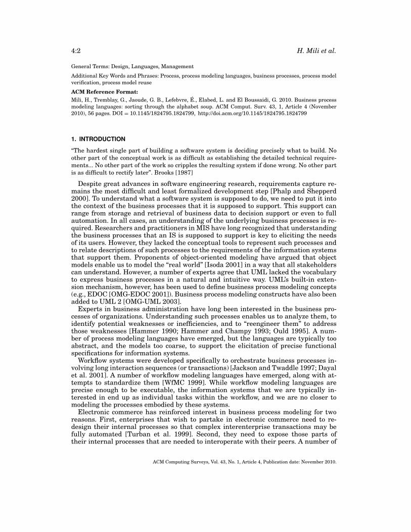
Different authors provide variations on the same set of themes. What emerges fromthese definitions is the following. The activities of a business process are performed byactors playing particular roles, consuming some resources and producing others. Activ-ities may be triggered by events and may, in turn, generate events of their own. The ac-tivities of a process may be linked through resource dependencies (producer-consumerdependencies) or control dependencies (one activity triggering another). The actors op-erate within the context of organizational boundaries. Organizations perform specificbusiness functions. Roles can support functions. Figure 1 shows a first-cut UML-likemodel (metamodel) of what a process is.
Before we go any further, we should make a distinction between process definitionsand process instances. A process definition deals with types of business data or re-sources. A process instance deals with specific instances of business data. For example,we could define what happens to a customer order in terms of triggering events (a callto customer service, or the submission of a web form), in terms of types of resources(the kind of items the customer might order), and in terms of roles (a customer serverrepresentative). A process instance deals with a specific customer (“John Smith”), spe-cific order contents, and a specific actor (“Beverly”) playing the role customer servicerepresentative. The metamodel in Figure 1 is mostly about process definitions. Onlythe class Actor and its associations carry instance semantics.
2.2. Why Business Processes
In the traditional view, a business is considered a hierarchical organization that re-flects both the functional decomposition of the enterprise and the chain of command.
ACM Computing Surveys, Vol. 43, No. 1, Article 4, Publication date: November 2010.
4:4 H. Mili et al.
Fig. 1. A first-cut business process metamodel.
Different departments specialize in specific business functions (e.g., marketing or pro-duction or accounting), and within each department, subdepartments, teams, and indi-viduals specialize in subfunctions. The processing of a customer order generally crossthe boundaries of various departments: sales (to take the order), planning (to planthe manufacture of the product or the replenishment of the inventory), production,shipping, and accounting. Early management theory focused on the workings of thehierarchy and on managing its branches effectively (chain of command, workflow, ac-countability, communication, etc.), but focusing on each branch in isolation [Hammerand Champy 1993]. With the so-called Business Process Reengineering trend, arevolution took place: instead of focusing on each business function separately—andthus not questioning the overall structure of the underlying business processes—researchers started to advocate that one should look at the entire business processthat is enacted to handle a business transaction from end to end, looking for ways tooptimize the business process in its entirety [Hammer 1990; Hammer and Champy1993]. This meant that different business processes did not necessarily cross the sameorganizational boundaries, or did not cross them in the same way. From the prac-tical side, this trend led to exotic organizational structures such as project-orientedmanagement whereby project teams are assembled from different functional units tohandle all aspects of a business transaction, or matrix organizations where businessunits (vertical) offer services to outside customers by relying on internal service units(horizontal).
Business process reengineering has renewed interest in business process modelingas a prerequisite for process analysis and improvement. A sample of research on busi-ness process analysis includes work done at MIT to develop a business process repos-itory [Malone et al. 1999]. Other research deals with assessing quality properties ofbusiness processes using structural metrics similar to those used in software [Phalp1998; Phalp and Shepperd 2000]. A number of researchers have tried to verify the dy-namic properties of processes such as liveness and absence of deadlock using formalmethods [Glykas and Valiris 1999; Gruhn and Wellen 2001]. The advent of electroniccommerce has further amplified interest in process modeling languages.
ACM Computing Surveys, Vol. 43, No. 1, Article 4, Publication date: November 2010.
Business Process Modeling Languages: Sorting Through the Alphabet Soup 4:5
2.3. An Ontology of Enterprises
Businesses have a wide variety of processes going on concurrently. The board of direc-tors has its own predefined processes for decision making, for nominating officers, fordesignating members of the board. The executive will have its own decision processesand distribution of responsibilities. Each functional department (accounting, market-ing, production, customer service, etc.) or business division (e.g., a bank might haveseparate divisions for personal financial services, corporate financial services, fundmanagement, etc.) will have its own processes, and so on. Each level of the organiza-tion, down to making security rounds or mail delivery, will have its own objectives, itsown processes, its own performance measurements to measure the extent to which agiven process helps attain the desired objectives. When we talk about “business pro-cess modeling,” we must identify which processes we are interested in, at what level ofdetail, and what are the relationships between these processes, if any.
Assume that a company aims at increasing its market share for its products. Thereare several ways to achieve this goal, including product innovation, competitive pric-ing, targeted marketing, building customer loyalty, responsive customer service, andso on. Assume that the company chooses to focus on competitive pricing and targetedmarketing. This would be the process followed by strategists at the enterprise level toachieve the goal of increased market share. Competitive pricing entails cost reduction,including engineering costs, production costs, distribution costs, and marketing costs.The organization may use a product development strategy based on the concept ofproduct lines to share the development of costs between several products. Product-lineengineering itself uses a specific engineering process, with its own sequence of steps,sub-steps, resources, and so on. Come the end of the year, suppose we compare the cur-rent market share of the company with that of the previous year . . . and it has actuallygone down. The attainment of the initial goal has triggered a number of processesat different levels of the organization, and any one of them, or combination thereof,might be at fault. It could be the focus on competitive pricing and targeted marketing:perhaps the product is labor-intensive with no room for automation and the companyoperates in a labor market with high labor costs. It could also be that the product-lineengineering approach was not appropriate, or that the specific product-line engineer-ing process was not effective.
The previous example shows that in order to gain a thorough understanding of howan organization works, we need to look at the processes at different levels of the organi-zation and how they relate to each other. In the above example, we were not concernedwith the process used by security guards. Clearly, some processes will have little bear-ing on the analysis at hand. Ould distinguishes between core processes, support pro-cesses, and management processes [Ould 1995]. The core processes are concerned withaddressing external requests from the enterprise—its customers. The support pro-cesses support its employees internally in executing the core processes. Managementprocesses manage both the core processes and the support processes. Very broadly,we analyze core processes to enhance customer satisfaction; we analyze support pro-cesses to enhance the enterprise efficiency; and we analyze management processes toenhance the enterprise structure.
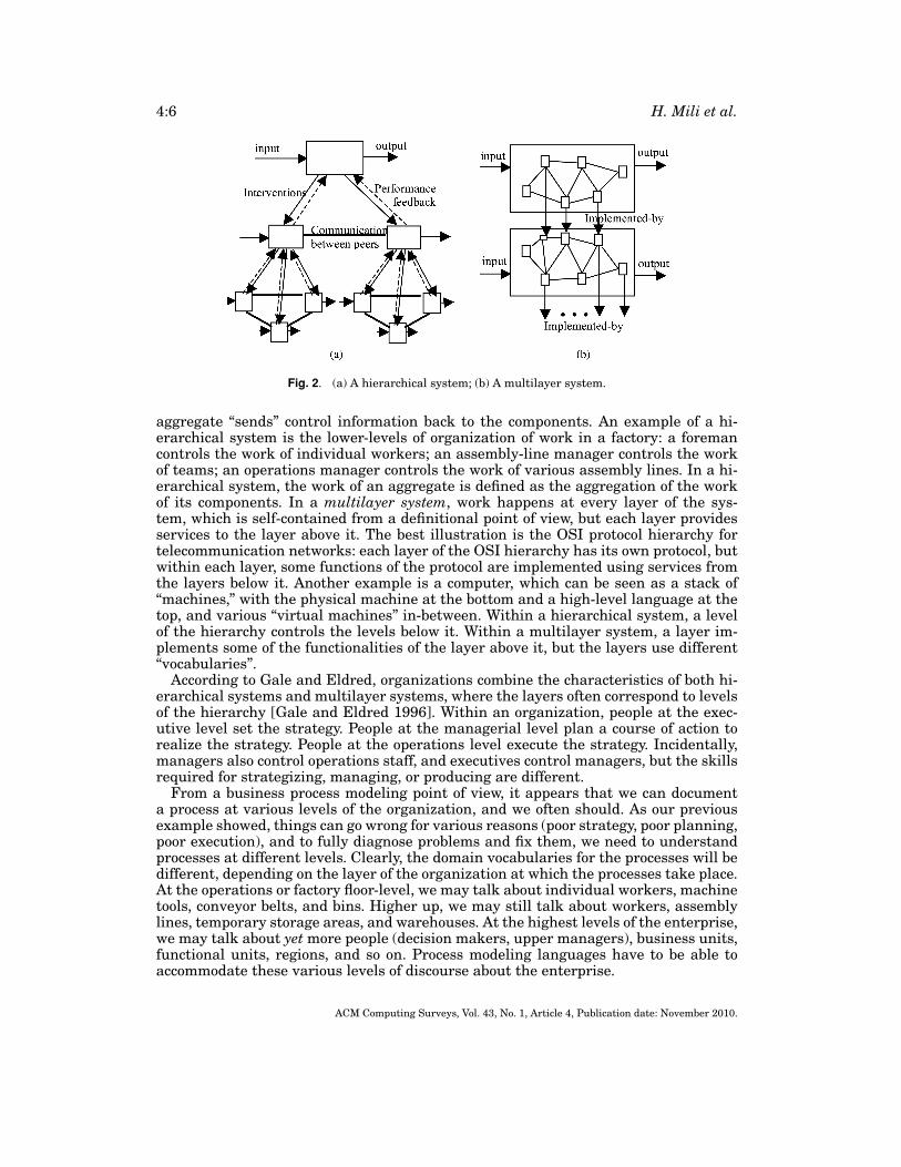
Gale and Eldred view an enterprise as a hierarchical multilayer system, thus com-bining the characteristics of hierarchical systems and multilayer systems [Gale andEldred 1996]. A hierarchical system is an aggregate system where each node in the ag-gregation hierarchy controls and coordinates its immediate components. Figure 2(a)illustrates an example of a hierarchical system. Control and coordination happensthrough two-way communication between an aggregate and its components: (i) thecomponents “send” information about their performance to the aggregate; and (ii) the
ACM Computing Surveys, Vol. 43, No. 1, Article 4, Publication date: November 2010.
4:6 H. Mili et al.
Fig. 2. (a) A hierarchical system; (b) A multilayer system.
aggregate “sends” control information back to the components. An example of a hi-erarchical system is the lower-levels of organization of work in a factory: a foremancontrols the work of individual workers; an assembly-line manager controls the workof teams; an operations manager controls the work of various assembly lines. In a hi-erarchical system, the work of an aggregate is defined as the aggregation of the workof its components. In a multilayer system, work happens at every layer of the sys-tem, which is self-contained from a definitional point of view, but each layer providesservices to the layer above it. The best illustration is the OSI protocol hierarchy fortelecommunication networks: each layer of the OSI hierarchy has its own protocol, butwithin each layer, some functions of the protocol are implemented using services fromthe layers below it. Another example is a computer, which can be seen as a stack of“machines,” with the physical machine at the bottom and a high-level language at thetop, and various “virtual machines” in-between. Within a hierarchical system, a levelof the hierarchy controls the levels below it. Within a multilayer system, a layer im-plements some of the functionalities of the layer above it, but the layers use different“vocabularies”.
According to Gale and Eldred, organizations combine the characteristics of both hi-erarchical systems and multilayer systems, where the layers often correspond to levelsof the hierarchy [Gale and Eldred 1996]. Within an organization, people at the exec-utive level set the strategy. People at the managerial level plan a course of action torealize the strategy. People at the operations level execute the strategy. Incidentally,managers also control operations staff, and executives control managers, but the skillsrequired for strategizing, managing, or producing are different.
From a business process modeling point of view, it appears that we can documenta process at various levels of the organization, and we often should. As our previousexample showed, things can go wrong for various reasons (poor strategy, poor planning,poor execution), and to fully diagnose problems and fix them, we need to understandprocesses at different levels. Clearly, the domain vocabularies for the processes will bedifferent, depending on the layer of the organization at which the processes take place.At the operations or factory floor-level, we may talk about individual workers, machinetools, conveyor belts, and bins. Higher up, we may still talk about workers, assemblylines, temporary storage areas, and warehouses. At the highest levels of the enterprise,we may talk about yet more people (decision makers, upper managers), business units,functional units, regions, and so on. Process modeling languages have to be able toaccommodate these various levels of discourse about the enterprise.
ACM Computing Surveys, Vol. 43, No. 1, Article 4, Publication date: November 2010.
Business Process Modeling Languages: Sorting Through the Alphabet Soup 4:7
3. A CLASSIFICATION OF BUSINESS PROCESS MODELING LANGUAGES
3.1. Kinds of Modeling Languages
As the history of process modeling languages showed (Sections 1 and 2), existing busi-ness process modeling languages come from different traditions and, as such, servedifferent purposes, and represent different things [Curtis et al. 1992]. Ould arguesthat business process modeling is useful for three basic reasons, which may in turnsupport several business goals [Ould 1995].
(1) Describing a process. We model a process to be able to describe it. We could havedifferent target audiences for these descriptions, for instance, humans, in whichcase understandability is important [Curtis et al. 1992], or machines, in which caseformality is important.
(2) Analyzing a process. Simply put, process analysis consists of assessing the proper-ties of a process. Process reengineering and improvement relies on an analysis ofexisting processes to identify redundant or suboptimal steps. If the process is de-scribed formally, we can verify mechanically structural properties such as couplingand cohesion [Phalp and Shepperd 2000] or dynamic properties such as the absenceof deadlock, liveness properties, and so on.
(3) Enacting a process. We may enact a process for simulation purposes or to providesome level of support for process execution. Depending on the language, this sup-port can take different forms: reacting to events triggered by the execution of theprocess, checking that specific constraints are satisfied, or driving the execution ofthe process [Curtis et al. 1992]. Only formal languages1 make process enactmentpossible. Language designers may put the emphasis on one of these basic usages,often at the expense of others.
Because business processes are complex, language designers generally provide differ-ent modeling views, each focusing on one aspect of the process. Curtis identified fourviews, summarized here [Curtis et al. 1992].
(1) The functional view presents the functional dependencies between the process ele-ments (activities, subprocesses, etc.). These dependencies are typically embodied inthe fact that some process elements consume (or need) data (or resources) producedby others. Typical notations used in the functional view include data flow diagrams.
(2) The dynamic (behavioral) view provides sequencing and control information aboutthe process, that is, when certain activities are performed (timing, pre-conditions)and how they are performed (e.g., by describing the control logic).
(3) The informational view includes the description of the entities that are produced,consumed, or otherwise manipulated by the process. These entities include puredata, artifacts, and products.
(4) The organizational view describes who performs each task or function, and where inthe organization (functionally and physically).
As is common with modeling methods, different notations may be appropriate for dif-ferent views.
Most object-oriented modeling methods include the first three views mentioned byCurtis et al., namely, the functional view, the dynamic view, and the informationalview (e.g., OOA/OOD, OMT [Rumbaugh et al. 1991]; OOSE [Jacobson et al. 1992];Fusion [Coleman et al. 1994; Shlaer and Mellor 1992]; and UML [Booch et al. 1999]).
1A language is considered to be formal if both its syntax and semantics can be precisely defined. When thesemantics is formally defined, sentences in the language then have a unique interpretation.
ACM Computing Surveys, Vol. 43, No. 1, Article 4, Publication date: November 2010.
4:8 H. Mili et al.
Some methods may amalgamate the functional and dynamic views,2 but in the end,the important concepts from these views are properly represented. What is new, froman ontological point of view, is the organizational view, which includes a description ofthe participants in the process as well as a description of the physical (location) andorganizational context within which this process is conducted. Furthermore, whereasthe informational view in object-oriented modeling represents only data entities, theinformational view of business processes modeling may represent tangible resourcesand artifacts that are used and produced by processes. We will elaborate more on thisdistinction in section Section 3.2.
Another interesting distinction is the one introduced more specifically in the contextof Web services between the orchestration view and the choreography view [Peltz 2003;Dijkman and Dumas 2004]. Whereas orchestration refers to a specific process—howthis process is to be performed, solely from that process perspective—choreographyrefers to the exchange of messages between various parties and sources, that is, chore-ography describes the message exchanges among the different parties involved in thevarious transactions.
3.2. Kinds of Modeling
Modeling may be seen as a mapping between two worlds, the modeled world and themodeling world. A modeling technique is defined by the way different things, conceptsor constructs in the modeled world are mapped to things, concepts or constructs in themodeling world. Typically, the things in the modeled world map to simpler things in themodeling world. This mapping is done in order to perform some operations on objectsin the modeling world that would not be possible on objects of the modeled world—toocostly, difficult to perform, and so on. Different modeling techniques embody differentperspectives, as they abstract different details from the modeled world, leaving onlythose aspects that are relevant for the tasks at hand. Most of us in the software fieldare familiar with modeling techniques, and more specifically, object-oriented modelingtechniques. Is business process modeling any different from the kind of modeling wedo with OMT or Fusion or RUP, and if so, in what ways?
Isoda distinguishes between two kinds of object-oriented modeling, what he calledreal-world modeling, and pseudo-real-world modeling [Isoda 2001]. He identifies threepossible uses of object-oriented modeling: (1) to gain an understanding of how the realworld functions; (2) to run a simulation of the real world; and (3) to write an applicationto automate parts of a business process—and shows that they call for different kindsof modeling [Isoda 2001]. He argues that the first two types of use call for real-worldmodeling, requiring a faithful representation of the modeled world, in this case, thereal world. In real-world modeling, entities of the real world and their properties aremapped to classes and attributes. The functions of the real-world entities are mappedto operations on those classes, and static relationships between the real-world entitiesare mapped to associations.
The third use of modeling, that is, its use to develop software that automates partsof the business process, requires both real-world modeling and pseudo-real-world mod-eling. We need real-world modeling to model the behavior of the business as it wouldexist with the automated system in place in order to elicit the functionalities of thesystem. In other words, we imagine what the process would be with the automatedsystem to better delineate the required functionalities [Isoda 2001]. “Real-world”
2OMT makes the distinction very clear [Rumbaugh et al. 1991], although it has been criticized for thedifficulty with which the functional model could be integrated into the object (informational) model.
ACM Computing Surveys, Vol. 43, No. 1, Article 4, Publication date: November 2010.
Business Process Modeling Languages: Sorting Through the Alphabet Soup 4:9
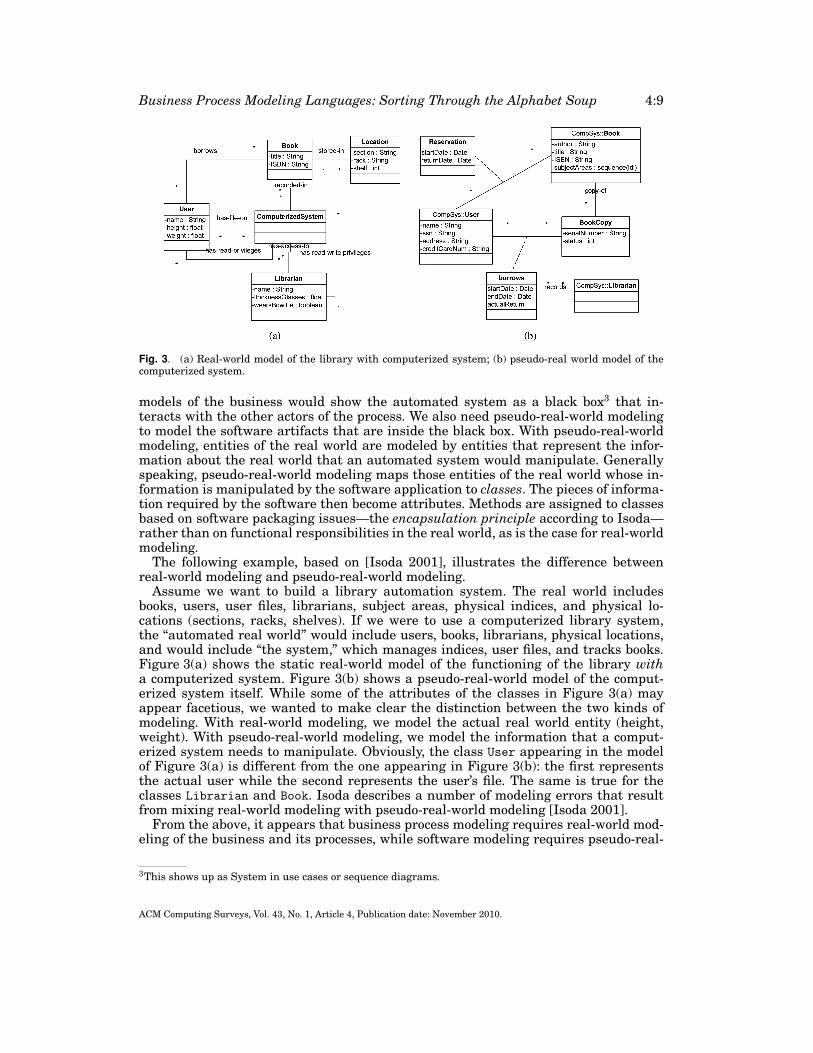
Fig. 3. (a) Real-world model of the library with computerized system; (b) pseudo-real world model of thecomputerized system.
models of the business would show the automated system as a black box3 that in-teracts with the other actors of the process. We also need pseudo-real-world modelingto model the software artifacts that are inside the black box. With pseudo-real-worldmodeling, entities of the real world are modeled by entities that represent the infor-mation about the real world that an automated system would manipulate. Generallyspeaking, pseudo-real-world modeling maps those entities of the real world whose in-formation is manipulated by the software application to classes. The pieces of informa-tion required by the software then become attributes. Methods are assigned to classesbased on software packaging issues—the encapsulation principle according to Isoda—rather than on functional responsibilities in the real world, as is the case for real-worldmodeling.
The following example, based on [Isoda 2001], illustrates the difference betweenreal-world modeling and pseudo-real-world modeling.
Assume we want to build a library automation system. The real world includesbooks, users, user files, librarians, subject areas, physical indices, and physical lo-cations (sections, racks, shelves). If we were to use a computerized library system,the “automated real world” would include users, books, librarians, physical locations,and would include “the system,” which manages indices, user files, and tracks books.Figure 3(a) shows the static real-world model of the functioning of the library witha computerized system. Figure 3(b) shows a pseudo-real-world model of the comput-erized system itself. While some of the attributes of the classes in Figure 3(a) mayappear facetious, we wanted to make clear the distinction between the two kinds ofmodeling. With real-world modeling, we model the actual real world entity (height,weight). With pseudo-real-world modeling, we model the information that a comput-erized system needs to manipulate. Obviously, the class User appearing in the modelof Figure 3(a) is different from the one appearing in Figure 3(b): the first representsthe actual user while the second represents the user’s file. The same is true for theclasses Librarian and Book. Isoda describes a number of modeling errors that resultfrom mixing real-world modeling with pseudo-real-world modeling [Isoda 2001].
From the above, it appears that business process modeling requires real-world mod-eling of the business and its processes, while software modeling requires pseudo-real-
3This shows up as System in use cases or sequence diagrams.
ACM Computing Surveys, Vol. 43, No. 1, Article 4, Publication date: November 2010.

4:10 H. Mili et al.
world modeling. Eliciting user requirements for a software application requires real-world modeling of the business with the automated system. Business process mod-eling does not require the presence of automated components. In the case of the li-brary, we could describe the borrowing process for an entirely manual library sys-tem, from searching index cards, to browsing through the shelves to find the book, torecording the book loan with a librarian. The interesting thing here is that the in-ternal process of the computerized library system mimics rather closely the manualprocess: instead of paper files and records and manual look-up, we have computer-ized records and computer-based lookup. This will often not be the case: the processimplemented by the computer component of the business process will often be differ-ent from the corresponding manual process.4 In other words, the model of the processwithout the computerized component—that is, the manual process—will not simplyconsist of the merging of the model of the business with the computerized componenttogether with the model of the computerized component. This idea was the premise be-hind the BPR movement: instead of blindly automating manual processes, we shouldre-engineer the processes while taking advantages of the possibilities for automation[Hammer 1990].
3.3. An Overview of Business Process Modeling Languages
In the remainder of this article, we will be studying a number of languages that weredeveloped with different objectives in mind, but that have all been used to describebusiness processes. The languages that we will study address different facets of busi-ness processes (dynamic, functional, informational, organizational), and may be moreor less formal, depending on the intended use and audience. There is no easy way ofcategorizing these languages along a single dimension, as they cut across several ofthe dimensions discussed earlier. Further, the last decade has seen the emergence of anumber of standards, with overlapping—not to say competing—objectives, and tortu-ous histories. However, the languages do fall under four broad but distinct scientific orprofessional traditions.
(1) Traditional process modeling languages. These languages mostly come from the MIStradition of information engineering and from work on business process engineer-ing. With one notable exception (Petri nets), they share concerns for understand-ability by people. These languages are typically not formal, but may lend them-selves to various informal or heuristic analyses. Languages in this category includeIDEF, Petri Nets, Event Process Chains (EPC) [Keller et al. 1992], Role ActivityDiagrams [Ould 1995], Resource-Event-Agent (REA) [McCarthy 1982], and the re-cently minted Business Process Modeling Language [BPMI 2003]. These languagesare presented in Section 4.
(2) Object-oriented languages. Despite its programming ancestry, object-oriented mod-eling has been vaunted from the beginning as a natural way of representing theworld in a way that both domain and IT experts can relate to (e. g., see Coadand Yourdon [1989] and Rumbaugh et al. [1991]). The question we raised in Sec-tion 3.2 was: “Which world”? After the “naivete” of the early years [Isoda 2001],the boundary between the problem domain (modeling the business) and the so-lution domain (modeling the software) has become well enough defined for usto realize that object-oriented modeling languages are, for the most part, gearedmore towards representing the solution (software) domain rather than the problem
4The two processes may be similar in the library system because libraries have been around for centuries,and we were able, as a civilization, to optimize the underlying processes.
ACM Computing Surveys, Vol. 43, No. 1, Article 4, Publication date: November 2010.
Business Process Modeling Languages: Sorting Through the Alphabet Soup 4:11
(business) domain, either because of inherent shortcomings or because of focus. Inthe section on OO languages, we will talk about UML 1.x, its extension mechanisms,as well as various extensions that were proposed in the literature to handle enter-prise modeling, including EDOC [OMG-EDOC 2001]. UML 2 also incorporated anumber of these extensions in its metamodel, and we will conclude that section bypresenting the new metamodel-level constructs introduced by UML 2 [OMG-UML2003]. These languages will be presented in Section 5.
(3) Dynamic process modeling languages. The past decade has seen the emergence ofa number of process modeling language standards proposed by various—mostlyindustrial—organizations. Chronologically, we will present the Workflow Manage-ment Coalition’s (WfMC) Workflow Process Description Language WPDL [WfMC1999], the Business Process Management Institute’s (bpmi.org) Business ProcessModeling Language BPM [BPMI 2003], OMG’s Business Process Modeling Notation[OMG-BPMN 2008], OASIS’s (www.oasis-open.org) WS-BPEL language [Andrews etal. 2003], and OMG’s Business Process Definition Metamodel BPDM [OMG-BPDM2007]. These languages will be presented in Section 6.
(4) Process integration languages. The advent of interenterprise electronic business(B2B) has spurred interest in process modeling languages for the purposes of in-tegrating the processes of two or more business partners. Such languages typi-cally focus on the mechanics of the integration in terms of abstract, technology-independent, programming interfaces and data exchange formats. Languages inthis category may also capture different levels of the semantics of the underlyingprocesses. Three such languages will be presented: RosettaNet [RosettaNet 2003],ebXML [ebXML 2003], and WS-CDL [Kavantas et al. 2004]. These languages willbe presented in Section 7.
4. TRADITIONAL PROCESS MODELING LANGUAGES
4.1. The IDEF Family
IDEF is a family of methods for enterprise modeling and analysis sponsored by theU.S. Air Force within the context of its long-running Integrated Computer-Aided Man-ufacturing (ICAM) program. The program, launched in the mid-seventies, sought toincrease manufacturing productivity through the systematic application of computertechnology. The program recognized (manufacturing) process analysis as an importanttool, and identified the need for better communication techniques to describe such pro-cesses. A family of modeling methods was introduced, referred to collectively as IDEF(ICAM Definition). Initially, three methods were planned: IDEF0 for functional model-ing; IDEF1 for information modeling; and IDEF2 for dynamic modeling. The methodshave since been updated and maintained under the stewardship of Knowledge BasedSystems Inc. under the sponsorship of the U.S. Commerce Department. New methodshave joined the family, IDEF4, which is an object-oriented modeling methodology, andIDEF5, which is a methodology for developing ontologies. In this section, we look atIDEF0 (functional modeling); IDEF1X (an extension of IDEF1); and IDEF3 (dynamicmodeling), which supersedes IDEF2.
4.1.1. IDEF0:Functional Modeling. IDEF0 was based on the Structured Analysis andDesign Technique (SADT) [Ross and Schoman 1977], a software analysis and designtechnique developed in the late seventies. It includes both a definition of a graphicalnotation, as well as a comprehensive methodology for developing functional models.
An IDEF0 model describes what a system does—its function—what controls it,what are its inputs, its outputs, and which services or other functions it needs to
ACM Computing Surveys, Vol. 43, No. 1, Article 4, Publication date: November 2010.
4:12 H. Mili et al.
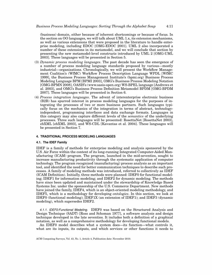
Fig. 4. (a) Anatomy of a function in IDEF0; (b) A functional diagram in IDEF0.
perform its function. An IDEF0 diagram consists of a graph where nodes, representedby boxes, represent functions, and where directed edges represent data flows and con-trol flows. Figure 4(a) shows what the function looks like. Figure 4(b) shows a samplediagram.
An IDEF0 model is a hierarchy of diagrams where a “box” at a given level maybe expanded into a graph (another diagram) at the lower level, enabling us to rep-resent functions at increasing levels of detail. Data flows between functions lead toimplicit control: a function can only start when all of its inputs are available. Dataflows also have richer semantics than is shown in Figure 4(b) (forks, joins, aggrega-tion/decomposition, etc.).
Clearly, IDEF0 covers only the functional view of a business process. Furthermore,it is not as rich as the data flow diagram notation used in the twin structured analy-sis/structured design techniques (e.g., Yourdon [1989]), which includes things such asdata stores, actors, sinks.
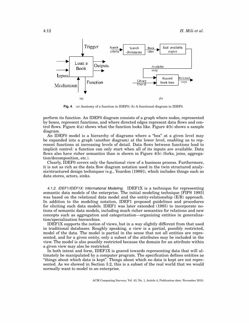
4.1.2. IDEF1/IDEF1X: Informational Modeling. IDEF1X is a technique for representingsemantic data models of the enterprise. The initial modeling technique [FIPS 1993]was based on the relational data model and the entity-relationship (E/R) approach.In addition to the modeling notation, IDEF1 proposed guidelines and proceduresfor eliciting such data models. IDEF1 was later extended (1985) to incorporate no-tions of semantic data models, including much richer semantics for relations and newconcepts such as aggregation and categorization—organizing entities in generaliza-tion/specialization hierarchies.
IDEF1X supports the notion of views, but in a way slightly different from that usedin traditional databases. Roughly speaking, a view is a partial, possibly restricted,model of the data. The model is partial in the sense that not all entities are repre-sented, and for a given entity, only a subset of the attributes may be included in theview. The model is also possibly restricted because the domain for an attribute withina given view may also be restricted.
In both intent and form, IDEF1X is geared towards representing data that will ul-timately be manipulated by a computer program. The specification defines entities as“things about which data is kept”. Things about which no data is kept are not repre-sented. As we showed in Section 3.2, this is a subset of the real world that we wouldnormally want to model in an enterprise.
ACM Computing Surveys, Vol. 43, No. 1, Article 4, Publication date: November 2010.
Business Process Modeling Languages: Sorting Through the Alphabet Soup 4:13
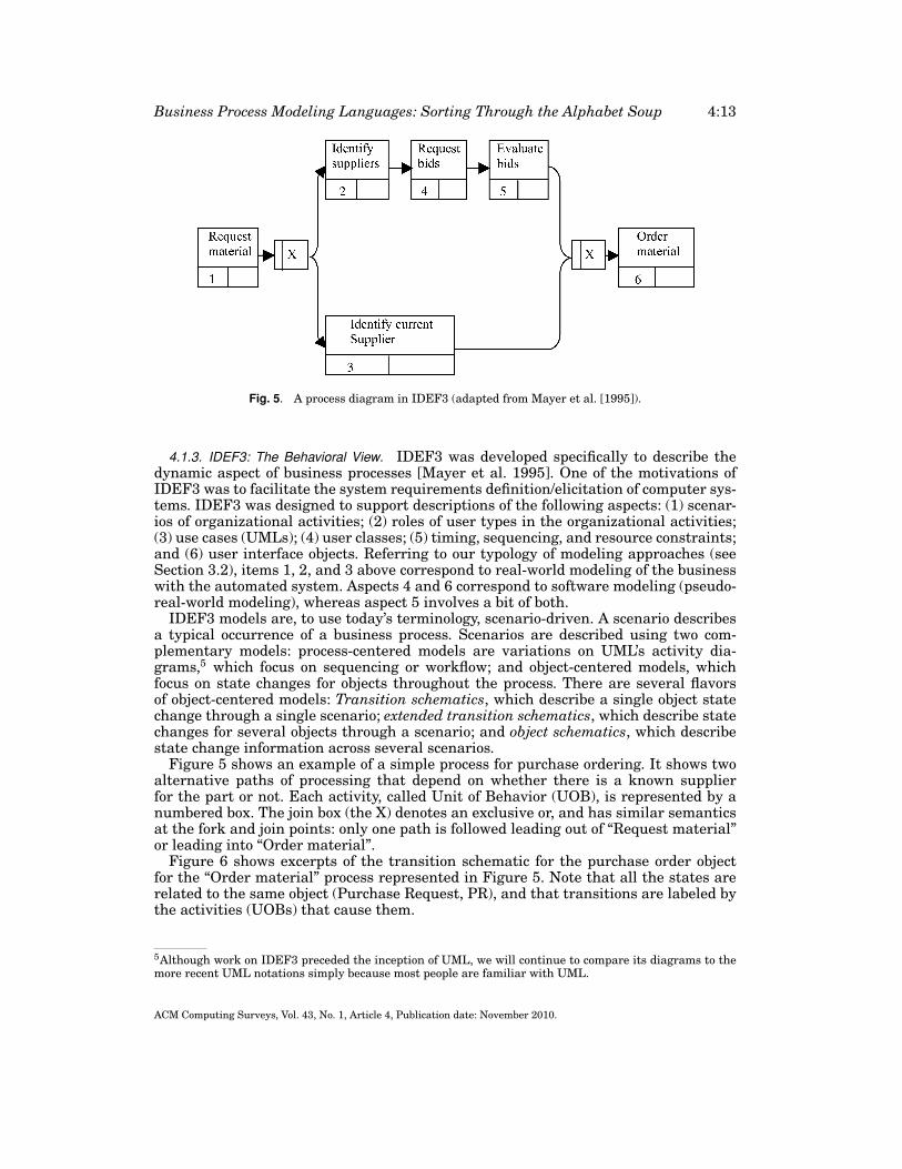
Fig. 5. A process diagram in IDEF3 (adapted from Mayer et al. [1995]).
4.1.3. IDEF3: The Behavioral View. IDEF3 was developed specifically to describe thedynamic aspect of business processes [Mayer et al. 1995]. One of the motivations ofIDEF3 was to facilitate the system requirements definition/elicitation of computer sys-tems. IDEF3 was designed to support descriptions of the following aspects: (1) scenar-ios of organizational activities; (2) roles of user types in the organizational activities;(3) use cases (UMLs); (4) user classes; (5) timing, sequencing, and resource constraints;and (6) user interface objects. Referring to our typology of modeling approaches (seeSection 3.2), items 1, 2, and 3 above correspond to real-world modeling of the businesswith the automated system. Aspects 4 and 6 correspond to software modeling (pseudo-real-world modeling), whereas aspect 5 involves a bit of both.
IDEF3 models are, to use today’s terminology, scenario-driven. A scenario describesa typical occurrence of a business process. Scenarios are described using two com-plementary models: process-centered models are variations on UML’s activity dia-grams,5 which focus on sequencing or workflow; and object-centered models, whichfocus on state changes for objects throughout the process. There are several flavorsof object-centered models: Transition schematics, which describe a single object statechange through a single scenario; extended transition schematics, which describe statechanges for several objects through a scenario; and object schematics, which describestate change information across several scenarios.
Figure 5 shows an example of a simple process for purchase ordering. It shows twoalternative paths of processing that depend on whether there is a known supplierfor the part or not. Each activity, called Unit of Behavior (UOB), is represented by anumbered box. The join box (the X) denotes an exclusive or, and has similar semanticsat the fork and join points: only one path is followed leading out of “Request material”or leading into “Order material”.
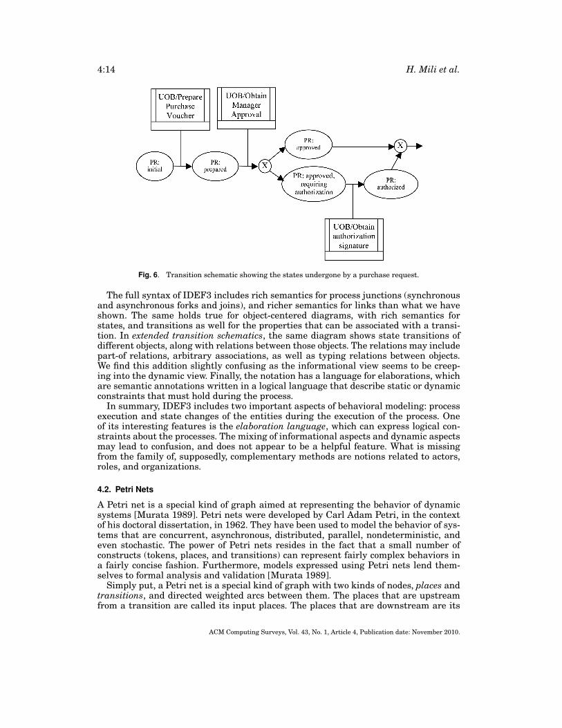
Figure 6 shows excerpts of the transition schematic for the purchase order objectfor the “Order material” process represented in Figure 5. Note that all the states arerelated to the same object (Purchase Request, PR), and that transitions are labeled bythe activities (UOBs) that cause them.
5Although work on IDEF3 preceded the inception of UML, we will continue to compare its diagrams to themore recent UML notations simply because most people are familiar with UML.
ACM Computing Surveys, Vol. 43, No. 1, Article 4, Publication date: November 2010.
4:14 H. Mili et al.
Fig. 6. Transition schematic showing the states undergone by a purchase request.
The full syntax of IDEF3 includes rich semantics for process junctions (synchronousand asynchronous forks and joins), and richer semantics for links than what we haveshown. The same holds true for object-centered diagrams, with rich semantics forstates, and transitions as well for the properties that can be associated with a transi-tion. In extended transition schematics, the same diagram shows state transitions ofdifferent objects, along with relations between those objects. The relations may includepart-of relations, arbitrary associations, as well as typing relations between objects.We find this addition slightly confusing as the informational view seems to be creep-ing into the dynamic view. Finally, the notation has a language for elaborations, whichare semantic annotations written in a logical language that describe static or dynamicconstraints that must hold during the process.
In summary, IDEF3 includes two important aspects of behavioral modeling: processexecution and state changes of the entities during the execution of the process. Oneof its interesting features is the elaboration language, which can express logical con-straints about the processes. The mixing of informational aspects and dynamic aspectsmay lead to confusion, and does not appear to be a helpful feature. What is missingfrom the family of, supposedly, complementary methods are notions related to actors,roles, and organizations.
4.2. Petri Nets
A Petri net is a special kind of graph aimed at representing the behavior of dynamicsystems [Murata 1989]. Petri nets were developed by Carl Adam Petri, in the contextof his doctoral dissertation, in 1962. They have been used to model the behavior of sys-tems that are concurrent, asynchronous, distributed, parallel, nondeterministic, andeven stochastic. The power of Petri nets resides in the fact that a small number ofconstructs (tokens, places, and transitions) can represent fairly complex behaviors ina fairly concise fashion. Furthermore, models expressed using Petri nets lend them-selves to formal analysis and validation [Murata 1989].
Simply put, a Petri net is a special kind of graph with two kinds of nodes, places andtransitions, and directed weighted arcs between them. The places that are upstreamfrom a transition are called its input places. The places that are downstream are its
ACM Computing Surveys, Vol. 43, No. 1, Article 4, Publication date: November 2010.
Business Process Modeling Languages: Sorting Through the Alphabet Soup 4:15
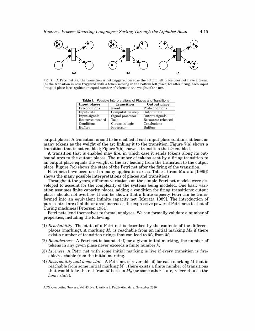
Fig. 7. A Petri net: (a) the transition is not triggered because the bottom left place does not have a token;(b) the transition is now triggered with a token moving in the bottom left place; (c) after firing, each input(output) place loses (gains) an equal number of tokens to the weight of the arc.
Table I. Possible Interpretations of Places and TransitionsInput places Transition Output placePreconditions Event Post-conditionsInput data Computation step Output dataInput signals Signal processor Output signalsResources needed Task Resources releasedConditions Clause in logic ConclusionsBuffers Processor Buffers
output places. A transition is said to be enabled if each input place contains at least asmany tokens as the weight of the arc linking it to the transition. Figure 7(a) shows atransition that is not enabled; Figure 7(b) shows a transition that is enabled.
A transition that is enabled may fire, in which case it sends tokens along its out-bound arcs to the output places. The number of tokens sent by a firing transition toan output place equals the weight of the arc leading from the transition to the outputplace. Figure 7(c) shows the state of the Petri net after the firing of the transition.
Petri nets have been used in many application areas. Table I (from Murata [1989])shows the many possible interpretations of places and transitions.
Throughout the years, different variations on the simple Petri net models were de-veloped to account for the complexity of the systems being modeled. One basic vari-ation assumes finite capacity places, adding a condition for firing transitions: outputplaces should not overflow. It can be shown that a finite capacity Petri can be trans-formed into an equivalent infinite capacity net [Murata 1989]. The introduction ofpure control arcs (inhibitor arcs) increases the expressive power of Petri nets to that ofTuring machines [Peterson 1981].
Petri nets lend themselves to formal analyses. We can formally validate a number ofproperties, including the following.
(1) Reachability. The state of a Petri net is described by the contents of the differentplaces (marking). A marking Mn is reachable from an initial marking M0 if thereexist a number of transition firings that can lead to Mn from M0.
(2) Boundedness. A Petri net is bounded if, for a given initial marking, the number oftokens in any given place never exceeds a finite number k.
(3) Liveness. A Petri net with some initial marking is live if every transition is fire-able/reachable from the initial marking.
(4) Reversibility and home state. A Petri net is reversible if, for each marking M that isreachable from some initial marking M0, there exists a finite number of transitionsthat would take the net from M back to M0 (or some other state, referred to as thehome state).
ACM Computing Surveys, Vol. 43, No. 1, Article 4, Publication date: November 2010.
4:16 H. Mili et al.
The fact that these properties are theoretically verifiable does not mean that they arecomputationally tractable. A number of transformations need to take place before (e.g.,see Murata [1989]). Current research with Petri nets deals with new application areasas well as reduction techniques that help make Petri nets computationally tractable.
Referring back to our classification in Section 3.1, Petri nets are clearly geared to-wards the modeling of the behavioral view. All of the other perspectives are literallymissing, although researchers have developed extensions with richer “token models”to account for structured data. Additionally, Petri nets are clearly not meant for com-municating models to business people, although many researchers have valued theiranalyzability, which makes it possible to validate properties about the processes theymodel (e.g., see Phalp [1998] and Glykas and Valiris [1999]). In summary, the Petri netformalism can be seen as a low-level language, almost a kind of assembly language-level modeling language. In fact, this is how Petri nets have been used in some formalspecification language toolboxes, for example, in the CADP toolbox [Fernandez et al.1996], where process algebraic specification written in the LOTOS language [Bolognesiand Brinksam 1987] are compiled into Petri nets in order to be analyzed.
4.3. Role Activity Diagrams (RAD)
The Role Activity Diagram is part of STRIMTM (Systematic Technique for Role andInteraction Modeling), a methodology developed by Praxis Plc. of Bath (U.K.) for the“elicitation, modeling, and analysis of business processes” [Ould 1995]. STRIM wasdeveloped from research aimed primarily at software process modeling by Ould andRoberts [1987]. The focus of STRIM—and RAD—is on developing models that are “re-vealing and communicative” [Ould 1995]. Ould identified five concepts that he consid-ered essential to STRIM: roles, actors, activities, interactions, and entities. Roles aretypes, such as project manager role. Within a given organization, different instancesof a given business process may be ongoing, and several instances of the role projectmanager may be active at the same time. Actors are individuals or systems that playa particular role (are bound to a role instance) at a given point in time. Activitiesare what actors do in their roles. In the process of performing their activities, actorsmay interact to exchange information or to control each other’s execution. Interac-tions may be binary or multiparty. Interactions are synchronous in the sense that theactors rendezvous to interact, for example, to exchange data. The data that actors ex-change through interactions is represented by entities. Ould stressed that data is nothis primary focus, but process is, and not surprisingly, the representation of entities issomewhat poor.
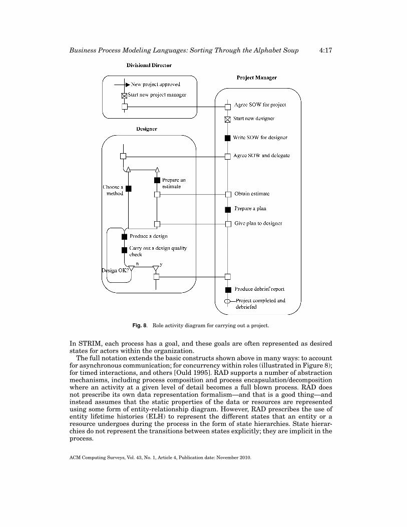
With these five ingredients, processes are represented using role activity diagrams.The following diagram illustrates the notation. The boxes with rounded corners rep-resent roles. There is an implicit timeline going down from the top, and the roles arelaid horizontally, side by side, much like UML’s swim lane activity diagrams; see alsoSection 7.1. White boxes represent end points of interactions. Black boxes representactivities. White boxes with diagonal lines indicate the instantiation of another role.Upward-pointing empty arrows represent concurrency. Downward-pointing empty ar-rows indicate branches of conditionals. External events are represented by horizontalarrows. In the example, the Divisional Director role receives the “New Project Ap-proved” event. States are represented by circles with a handle around the time line.
In the process shown in Figure 8, the divisional director instantiates the projectmanager role, which, in turn, instantiates the designer role. Note that each role instan-tiates another role and then interacts with it. Also, the project manager role definesthe tasks that the designer role will perform (statement of work, or SOW). Finally, notethe final state of the process, embodied in the state “Project completed and debriefed”.
ACM Computing Surveys, Vol. 43, No. 1, Article 4, Publication date: November 2010.
Business Process Modeling Languages: Sorting Through the Alphabet Soup 4:17
Fig. 8. Role activity diagram for carrying out a project.
In STRIM, each process has a goal, and these goals are often represented as desiredstates for actors within the organization.
The full notation extends the basic constructs shown above in many ways: to accountfor asynchronous communication; for concurrency within roles (illustrated in Figure 8);for timed interactions, and others [Ould 1995]. RAD supports a number of abstractionmechanisms, including process composition and process encapsulation/decompositionwhere an activity at a given level of detail becomes a full blown process. RAD doesnot prescribe its own data representation formalism—and that is a good thing—andinstead assumes that the static properties of the data or resources are representedusing some form of entity-relationship diagram. However, RAD prescribes the use ofentity lifetime histories (ELH) to represent the different states that an entity or aresource undergoes during the process in the form of state hierarchies. State hierar-chies do not represent the transitions between states explicitly; they are implicit in theprocess.
ACM Computing Surveys, Vol. 43, No. 1, Article 4, Publication date: November 2010.
4:18 H. Mili et al.
What can we do with a RAD process model? Ould stressed that STRIM—and itsmain notation RAD—are aimed at developing models that are “revealing and com-municative” [Ould 1995]. He proposed an analysis method based on using a combi-nation of simulation, local optimization, and the detection of “anti-patterns”. Sim-ulation relies on the propagation of tokens throughout the diagram, reflecting theprogress of the process, much like with Petri nets. The other two methods rely on com-mon sense heuristics whereby one submits a RAD model to a series of validations orquestions aimed at identifying redundancies, conflicts, and so on. Other researchershave attempted formal analysis of RADs since then (e.g., see Phalp and Shepperd[2000]).
4.4. Event Process Chains (EPC)
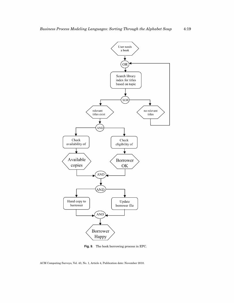
The Event Process Chains method was developed in the early nineties in a joint ef-fort between researchers at the University of Saarland and SAP [Keller et al. 1992].Event process chains (EPC) are used to describe business processes at the informalbusiness level, and are meant to support business users rather than to perform formalmanipulations.
Event process chains are composed of three basic ingredients: events, functions, andconnectors. Figure 9 represents a book-borrowing process using the EPC notation.Within a process chain, functions and events alternate, possibly separated by con-nectors. Functions have exactly one inbound arc and one outbound arc. Events haveat most one inbound arc and at most one outbound arc. Events in EPC are half-waybetween real events, as occurrences with no “duration,” and states, as steady condi-tions of the process or of some entities manipulated by it.6 Connectors can have mul-tiple inbound arcs and a single outbound arc, or the opposite. They have somewhatsimilar semantics to connectors in IDEF3. An AND connector with one inbound arcbut two or more outbound arcs means that the current process is forking into manyparallel threads. An AND connector with two or more inbound arcs and a single out-bound arc plays the role of a process join. A forking XOR connector means that onlyone of the outbound branches is taken. A joining XOR connector means that onlyone possible path can lead to the current function. A joining OR connector meansthat two or more possible paths can lead to the next function. A forking OR con-nector means two alternative courses of action, which are not necessarily mutuallyexclusive.
The ERP and BPR tools that use EPC diagrams augment them with a description ofthe inputs and outputs of the various functions, and with references to other diagramsshowing:
(1) a data model, such as an entity relationship diagram, showing the structure of theinputs/outputs;
(2) a hierarchical organization of the enterprise, and links between the functions of theEPC diagram and the actors (departments, individuals) who perform the work;
(3) a hierarchical functional decomposition diagram and cross-references to the func-tions in the EPC diagram; and
(4) an entity life history-like diagram (see discussion of entity life histories in Section4.3) showing the various states that entities can take during the process.
In terms of practical use, EPC is one of the most widely used languages for processmodeling, with SAP and the major BPR tool vendors supporting it.
6Some of the literature refers to states as preconditions and postconditions of the functions.
ACM Computing Surveys, Vol. 43, No. 1, Article 4, Publication date: November 2010.
Business Process Modeling Languages: Sorting Through the Alphabet Soup 4:19
Fig. 9. The book borrowing process in EPC.
ACM Computing Surveys, Vol. 43, No. 1, Article 4, Publication date: November 2010.
4:20 H. Mili et al.
From a theoretical point of view, several researchers have tried to map EPCs toPetri nets to take advantage of Petri nets formal analysis arsenal. However, EPC wasshown to suffer from ambiguous semantics (v. d. Aalst [1999] and Kindler [2003]). Forexample, the meaning of the joining XOR is not clearly stated in the original EPC[Keller et al. 1992]7. Interestingly, it is not clear what that meaning should be, ei-ther; but also note that the same could probably be said about IDEF3’s join boxes (seeSection 4.1.3).
Although not as rich as Petri nets or RADs, EPCs are interesting because of theiruse in commercial products. They are supported by major vendors of enterprise re-source planning solutions and business process reengineering tools (e.g., SAP, Aris,LiveModel/Analyst). This may be an indication about the level of complexity that realusers can tolerate.
4.5. Resource Event Agent (REA)
The Resource Event Agent (REA) framework is another triad that has been used tomodel business processes [McCarthy 1982], and that may be gaining ground as a pro-cess modeling framework for interenterprise commerce [Haugen and McCarthy 2000].In a pioneering paper, William McCarthy proposed the Resource Event Agent frame-work as a way of representing accounting information that would solve the problemsexperienced by existing accounting procedures and accounting software, including Mc-Carthy [1980]:
(1) Limited dimensions in the accounting data, supporting a limited number of mea-sures.
(2) A rigid and too coarse classification of accounting data, leading to inappropriateclassification of accounting entries or to ignoring some accounting information.
(3) High aggregation level of accounting data, precluding analyses by decision makerswho may need different views on the data,
(4) Poor (or lack of) integration with other data contained in information systems.
According to McCarthy [1980] and Geerts and McCarthy [1997], today’s accountingsystems use bookkeeping principles (double entry) first laid out more than 500 yearsby Luca Pacioli, a Franciscan monk from Venice. The REA framework aims at a moredetailed and more expressive representation of what “needs to be counted,” and whichare, primarily, economic resources and economic events. Economic resources are de-fined as objects that are scarce and have utility, and are under the control of an enter-prise [Ijiri 1975]. Economic events are defined as “a class of phenomena which reflectchanges in scarce means [economic resources] resulting from production, exchange,consumption, and distribution” [Yu 1976]. Actors come into play as participants in eco-nomic events [McCarthy 1982].
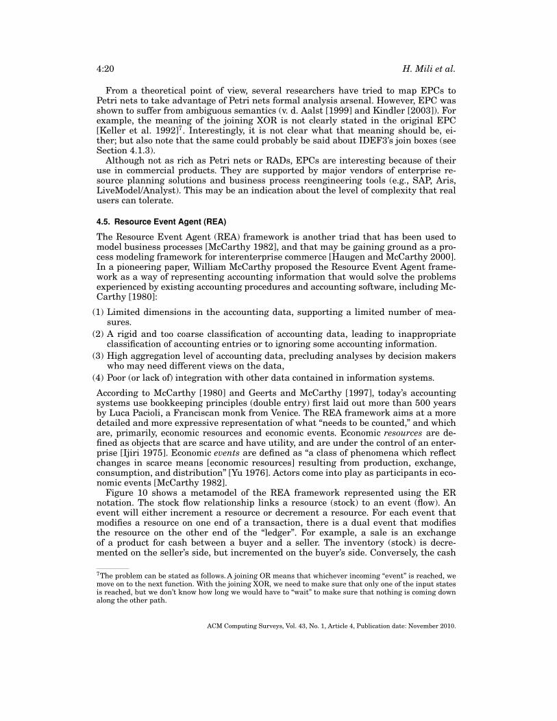
Figure 10 shows a metamodel of the REA framework represented using the ERnotation. The stock flow relationship links a resource (stock) to an event (flow). Anevent will either increment a resource or decrement a resource. For each event thatmodifies a resource on one end of a transaction, there is a dual event that modifiesthe resource on the other end of the “ledger”. For example, a sale is an exchangeof a product for cash between a buyer and a seller. The inventory (stock) is decre-mented on the seller’s side, but incremented on the buyer’s side. Conversely, the cash
7The problem can be stated as follows. A joining OR means that whichever incoming “event” is reached, wemove on to the next function. With the joining XOR, we need to make sure that only one of the input statesis reached, but we don’t know how long we would have to “wait” to make sure that nothing is coming downalong the other path.
ACM Computing Surveys, Vol. 43, No. 1, Article 4, Publication date: November 2010.
Business Process Modeling Languages: Sorting Through the Alphabet Soup 4:21
Fig. 10. The REA framework metamodel [McCarthy 1982].
is decremented on the buyer’s side, but incremented on the seller’s side. The actors in-volved in an economic event are classified into economic agents (actors outside theorganization) and economic units (actors within the organization). Economic unitsrepresent both individuals and units, such as departments or teams. The responsi-bility relationship reflects the hierarchical relationships (subordination) within theorganization.
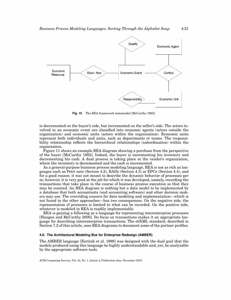
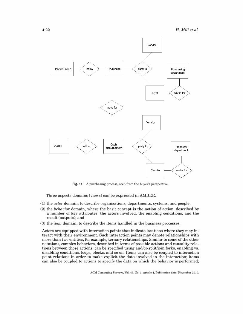
Figure 11 shows an example REA diagram showing a purchase from the perspectiveof the buyer [McCarthy 1982]. Indeed, the buyer is incrementing his inventory anddecrementing his cash. A dual process is taking place at the vendor’s organization,where the inventory is decremented and the cash is incremented.
As a general-purpose business process modeling language, REA is not as rich as lan-guages such as Petri nets (Section 4.2), RADs (Section 4.3) or EPCs (Section 4.4), andfor a good reason: it was not meant to describe the dynamic behavior of processes perse; however, it is very good at the job for which it was developed, namely, recording thetransactions that take place in the course of business process execution so that theymay be counted. An REA diagram is nothing but a data model to be implemented bya database that both accountants (and accounting software) and other decision mak-ers may use. The overriding concern for data modeling and implementation—which isnot found in the other approaches—has two consequences. On the negative side, therepresentation of processes is limited to what can be recorded. On the positive side,whatever is modeled in REA is readily implementable.
REA is gaining a following as a language for representing interenterprise processes[Haugen and McCarthy 2000]. Its focus on transactions makes it an appropriate lan-guage for describing interenterprise transactions. The ebXML standard, described inSection 7.2 of this article, uses REA diagrams to document some of the partner profiles.
4.6. The Architectural Modeling Box for Enterprise Redesign (AMBER)
The AMBER language [Eertink et al. 1999] was designed with the dual goal that themodels produced using this language be highly understandable and, yet, be analyzableby the appropriate software tools.
ACM Computing Surveys, Vol. 43, No. 1, Article 4, Publication date: November 2010.
4:22 H. Mili et al.
Fig. 11. A purchasing process, seen from the buyer’s perspective.
Three aspects domains (views) can be expressed in AMBER:
(1) the actor domain, to describe organizations, departments, systems, and people;(2) the behavior domain, where the basic concept is the notion of action, described by
a number of key attributes: the actors involved, the enabling conditions, and theresult (outputs); and
(3) the item domain, to describe the items handled in the business processes.
Actors are equipped with interaction points that indicate locations where they may in-teract with their environment. Such interaction points may denote relationships withmore than two entities, for example, ternary relationships. Similar to some of the othernotations, complex behaviors, described in terms of possible actions and causality rela-tions between those actions, can be specified using and/or-split/join forks, enabling vs.disabling conditions, loops, blocks, and so on. Items can also be coupled to interactionpoint relations in order to make explicit the data involved in the interaction; itemscan also be coupled to actions to specify the data on which the behavior is performed;
ACM Computing Surveys, Vol. 43, No. 1, Article 4, Publication date: November 2010.
Business Process Modeling Languages: Sorting Through the Alphabet Soup 4:23
although no special language is used for specifying data items—a subset of UML isexpected to be used.
Although the process description notation of AMBER does not seem to bring any newmajor concepts, the variety of formal analyses that can be performed on the models iscertainly the most interesting feature of AMBER. Analyzability is attained through anumber of formal models used for different aspects. For instance, a number of struc-tural analyses are based strictly on the formal syntax, for example, control or data flowanalysis. Behavioral properties can be analyzed based on an appropriate operationalsemantics, including checking temporal properties using model-checking [Janssen etal. 1998]. Quantitative properties (e.g., performance, completion time, or critical pathsanalysis) are analyzed using techniques based on queuing theory or graph models.
5. OBJECT-ORIENTED LANGUAGES
Object-oriented models have long been touted as information models that both busi-ness people and technologists can understand [Coad and Yourdon 1988; Henderson-Sellers and Edwards 1990; Isoda 2001]. However, the focus has mostly been on infor-mation system modeling, as opposed to business process modeling. Do object-orientedmodeling languages have what it takes to model business processes? Clearly, in com-parison to the business process modeling languages seen so far, and using the ontologyshown in Section 2.3, object-oriented notations support a good many concepts neededfor business process modeling. On the other hand, they are also missing importantones, such as the notion of a role, and organizational aspects, with one notable excep-tion: OORAM [Reenskaug 1996]. EDOC used UML’s built-in extension mechanism toadd a business process profile [OMG-EDOC 2001]. Some of the important concepts thatwere proposed by EDOC were integrated into the core of UML 2 [OMG-UML 2003]. Wefirst start by discussing OORAM. We then talk about EDOC by first discussing UML1.x constructs for process modeling, and then talk about the extensions proposed byEDOC. We conclude this section by discussing UML 2’s new features.
5.1. OORAM
The Object-Oriented Role Analysis Methodology (OORAM) is a joint effort of the Cen-ter for Industrial Research in Oslo, TASKON AS, and the University of Oslo [Reen-skaug 1996]. OORAM recognizes a class as the appropriate implementation paradigmfor objects, but advocate the concept of roles and role models as the appropriate mod-eling abstractions. The general idea is as follows. An object plays different roles inan information system. Each role corresponds to a coherent set of collaborations inwhich the object participates, fulfilling its share of a common function. Role models de-scribe the structure and behavior of collaborating objects in terms of roles as opposedto classes [Reenskaug 1996]. The mapping of roles to classes is a design decision, andthe mapping can be many to many. A key step in this mapping is role synthesis wherebyit is determined that certain roles are to be synthesized so that they could be played bythe same objects. Reenskaug compares role synthesis to inheritance in the followingterms:
(1) Inheritance (specialization) is used in programming both for concept building andfor code sharing, which are two different intellectual activities;
(2) Role synthesis is used exclusively for model building, thus separating the twoactivities.
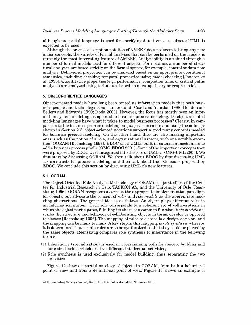
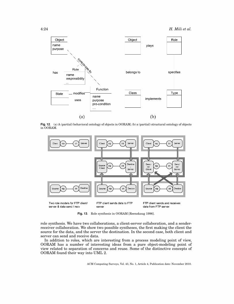
Figure 12 shows a partial ontology of objects in OORAM, from both a behavioralpoint of view and from a definitional point of view. Figure 13 shows an example of
ACM Computing Surveys, Vol. 43, No. 1, Article 4, Publication date: November 2010.
4:24 H. Mili et al.
Fig. 12. (a) A (partial) behavioral ontology of objects in OORAM; (b) a (partial) structural ontology of objectsin OORAM.
Fig. 13. Role synthesis in OORAM [Reenskaug 1996].
role synthesis. We have two collaborations, a client-server collaboration, and a sender-receiver collaboration. We show two possible syntheses, the first making the client thesource for the data, and the server the destination. In the second case, both client andserver can send and receive data.
In addition to roles, which are interesting from a process modeling point of view,OORAM has a number of interesting ideas from a pure object-modeling point ofview related to separation of concerns and reuse. Some of the distinctive concepts ofOORAM found their way into UML 2.
ACM Computing Surveys, Vol. 43, No. 1, Article 4, Publication date: November 2010.
Business Process Modeling Languages: Sorting Through the Alphabet Soup 4:25
5.2. EDOC
EDOC is an OMG standard modeling framework aimed at simplifying the develop-ment of component-based enterprise distributed object computing (EDOC) systems.The modeling framework was based on UML 1.4 and conformed to OMG’s MDA devel-opment [OMG-MDA 2003]. The standard built on the experience of several companies(the submitters) in the area of modeling of enterprise distributed object computing sys-tems, including Data Access Technologies, EDS, Fujitsu, Iona, IBM, Sun, and others.Two factors make this modeling framework particularly relevant to our needs:
(1) an extension of UML to provide explicit representation for business processes—thebusiness process profile; and
(2) a built-in traceability mechanism that enables us to trace software components tothe actors and activities of the business processes that they support.
We first discuss the principles underlying EDOC. In Section 5.2.2, we discuss theComponent Collaboration Architecture (CCA), which is the technical core of EDOC—and the basis for the business process modeling framework. Finally, we discuss thebusiness processing framework.
5.2.1. Principles. The EDOC standard consists of two major parts: (1) a set of ex-tensions to UML (profiles) to model enterprise distributed object computing (EDOC)systems; and (2) a framework for the application of these extensions to model EDOCsystems in a way that is consistent with the MDA development model. The UML ex-tensions include the following:
(1) the Enterprise Collaboration Architecture (ECA), which in turn consists of fiveprofiles—discussed shortly—each embodying a different view of an EDOC system;
(2) a patterns profile, enabling us to model recurring ECA patterns and applying themto specific EDOC systems; and
(3) a set of technology-specific models allowing the definition of platform-dependentmodels, a la MDA.
The five profiles included in the ECA are as follows.
(1) The Component Collaboration Architecture (CCA), which views a system as consist-ing of a set of components participating in collaborations in which they play specificroles to fulfill an overall function.
(2) The Entities profile, which provides UML extensions to represent problem domainconcepts—as opposed to software artifacts, something that UML classes are sup-posed to handle.
(3) The Events profile, which provides UML extensions to model event-driven systems.(4) The Business Process profile, which specializes the CCA and focuses on the case
when the components are business activities, tasks or processes.(5) The Relationships profile, which extends UML’s support for the definition of associ-
ations with richer semantics.
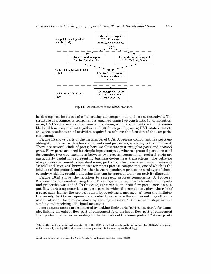
These profiles are to be used to represent different viewpoints of an EDOC system.In particular, the EDOC standard considers the five viewpoints of the reference modelfor open distributed processing (RM-ODP), namely, the enterprise viewpoint, the com-putational viewpoint, the informational viewpoint, the engineering viewpoint, and thetechnology viewpoint. We discuss them briefly, in turn.
The enterprise viewpoint is embodied in an enterprise specification, which “mod-els the structure and behavior of the system in the context of the business
ACM Computing Surveys, Vol. 43, No. 1, Article 4, Publication date: November 2010.
4:26 H. Mili et al.
organization of which it forms a part” [OMG-EDOC 2001]. Referring back to ourdiscussion in Section 3.2, the enterprise specification corresponds to the real-worldmodeling of the enterprise with the automated EDOC system in place. This model-ing is done in terms of (i) the business processes supported (in part) by the system;(ii) the steps in those processes and their inter-relationships; (iii) the business rulesthat apply to those steps; (iv) the artifacts acted upon by those steps (resources, en-tities); (v) enterprise objects representing the business entities involved (individuals,departments, other automated systems); (vi) the roles that they fulfill in supportingthe business processes; and (vii) the relationships between those roles. A key conceptin enterprise specification is the notion of community, which is a set of entities in-teracting to achieve some purpose. Communities are represented by composed compo-nents, with associated composition and choreography definitions. We will discuss com-ponents and compositions in more detail in the next section (Component CollaborationArchitecture).
The computation viewpoint is embodied in a computational specification, which de-scribes the implementation of the EDOC system (or its components) in order to carryout the functionality identified in the enterprise specification. This implementation isdescribed in terms of interactions between computational components that interactthrough well-defined interfaces (used and provided) to achieve some function.
The EDOC computational specification uses the CCA profile, which is discussed inthe next section. A component in the computational specification is related to one ormore activities in one or more processes in the enterprise specification. Furthermore,an entity in the computational specification corresponds to an entity referenced in anactivity or process of the enterprise specification.
The informational viewpoint is embodied in the information specification whichdescribes the semantics of the information and of the information processing per-formed by the system, regardless of software packaging—embodied in the computa-tional viewpoint. The information specification includes a configuration of informationobjects as well as a functional description of those objects in terms of states, tran-sitions, and constraints on the entities of the system. The information objects corre-spond to the enterprise objects in the enterprise specification for which informationis held and processed by the system. Information objects are modeled as entities andrelationships.
The engineering specification defines the architecture of the EDOC system in termsof infrastructure services such as distribution, persistence, and transactions. It is con-structed by mapping the computational specification to technology abstraction models.The technology specification is concerned with the mapping of the engineering speci-fication to a specific hardware and software platform such as EJB, CORBA, COM+,and so on. Note that the engineering specification is not concerned with the plat-form, but does embody general design decisions to be realized or implemented by theplatform.
Figure 14 shows the relationship between the different viewpoints, and the profilesused by each viewpoint. In terms of MDA levels, the enterprise specification corre-sponds to computation independent models; the computational specification, the in-formational specification, and the engineering specifications correspond to platform-independent models; and the technology specification corresponds to platform-specificmodels.
5.2.2. The Component Collaboration Architecture. The component collaboration architec-ture views a system as a set of components that interact through a set of ports ac-cording to a set of protocols. Components, called ProcessComponents, may themselves
ACM Computing Surveys, Vol. 43, No. 1, Article 4, Publication date: November 2010.
Business Process Modeling Languages: Sorting Through the Alphabet Soup 4:27
Fig. 14. Architecture of the EDOC standard.
be decomposed into a set of collaborating subcomponents, and so on, recursively. Thestructure of a composite component is specified using two constructs: (1) composition,using UML’s collaboration diagrams and showing which components are to be assem-bled and how they are put together; and (2) choreography, using UML state charts toshow the coordination of activities required to achieve the function of the compositecomponent.
Figure 15 shows parts of the metamodel of CCA. A process component has ports en-abling it to interact with other components and properties, enabling us to configure it.There are several kinds of ports; here we illustrate just two, flow ports and protocolports. Flow ports are used for simple inputs/outputs, whereas protocol ports are usedfor complex two-way exchanges between two process components; protocol ports areparticularly useful for representing business-to-business transactions. The behaviorof a process component is specified using protocols, which are a sequence of message“sends” and “receives” between two (or more) process components, one of which is theinitiator of the protocol, and the other is the responder. A protocol is a subtype of chore-ography which is, roughly, anything that can be represented by an activity diagram.
Figure 16(a) shows the notation to represent process components. A Process-Component is represented using the UML subsystem icon, to which notation for portsand properties was added. In this case, Receives is an input flow port; Sends an out-put flow port; Responder is a protocol port in which the component plays the role ofa responder. Hence, the protocol starts by receiving a message (A) from the initiator.Conversely, Initiator represents a protocol port where the component plays the roleof an initiator. The protocol starts by sending message X. Subsequent steps involvesending and receiving additional messages.ProcessComponents are connected by linking their ports (port connectors), for exam-
ple, linking an output flow port of component A to an input flow port of componentB, or protocol ports corresponding to the two roles of the same protocol.8 A composite
8The authors of the standard asserted that the CCA standard was heavily influenced by OORAM, discussedin Section 5.1, and by ROOM, a real-time object-oriented modeling methodology.
ACM Computing Surveys, Vol. 43, No. 1, Article 4, Publication date: November 2010.
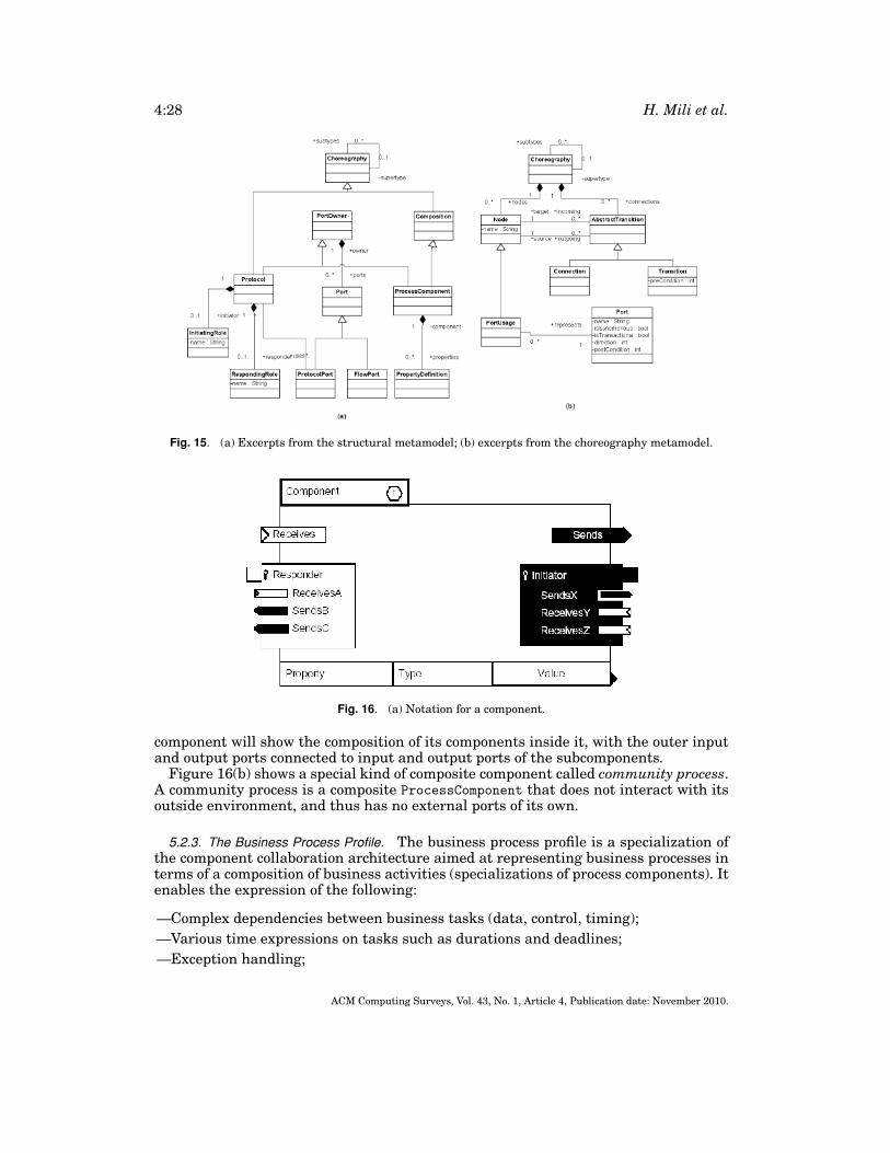
4:28 H. Mili et al.
Fig. 15. (a) Excerpts from the structural metamodel; (b) excerpts from the choreography metamodel.
Fig. 16. (a) Notation for a component.
component will show the composition of its components inside it, with the outer inputand output ports connected to input and output ports of the subcomponents.
Figure 16(b) shows a special kind of composite component called community process.A community process is a composite ProcessComponent that does not interact with itsoutside environment, and thus has no external ports of its own.
5.2.3. The Business Process Profile. The business process profile is a specialization ofthe component collaboration architecture aimed at representing business processes interms of a composition of business activities (specializations of process components). Itenables the expression of the following:
—Complex dependencies between business tasks (data, control, timing);—Various time expressions on tasks such as durations and deadlines;—Exception handling;
ACM Computing Surveys, Vol. 43, No. 1, Article 4, Publication date: November 2010.
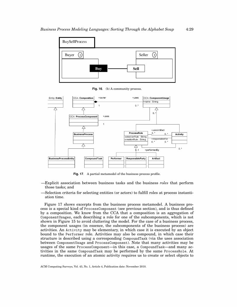
Business Process Modeling Languages: Sorting Through the Alphabet Soup 4:29
Fig. 16. (b) A community process.
Fig. 17. A partial metamodel of the business process profile.
—Explicit association between business tasks and the business roles that performthose tasks; and
—Selection criteria for selecting entities (or actors) to fulfill roles at process instanti-ation time.
Figure 17 shows excerpts from the business process metamodel. A business pro-cess is a special kind of ProcessComponent (see previous section), and is thus definedby a composition. We know from the CCA that a composition is an aggregation ofComponentUsages, each describing a role for one of the subcomponents, which is notshown in Figure 15 to avoid cluttering the model. For the case of a business process,the component usages (in essence, the subcomponents of the business process) areactivities. An Activity may be elementary, in which case it is executed by an objectbound to the Performer role. Activities may also be compound, in which case theirstructure is described using a corresponding CompoundTask (via the uses associationbetween ComponentUsage and ProcessComponent). Note that many activities may beusages of the same ProcessComponent—in this case, a CompoundTask—and many ac-tivities in the same CompoundTask may be performed by the same ProcessRole. Atruntime, the execution of an atomic activity requires us to create or select objects to
ACM Computing Surveys, Vol. 43, No. 1, Article 4, Publication date: November 2010.
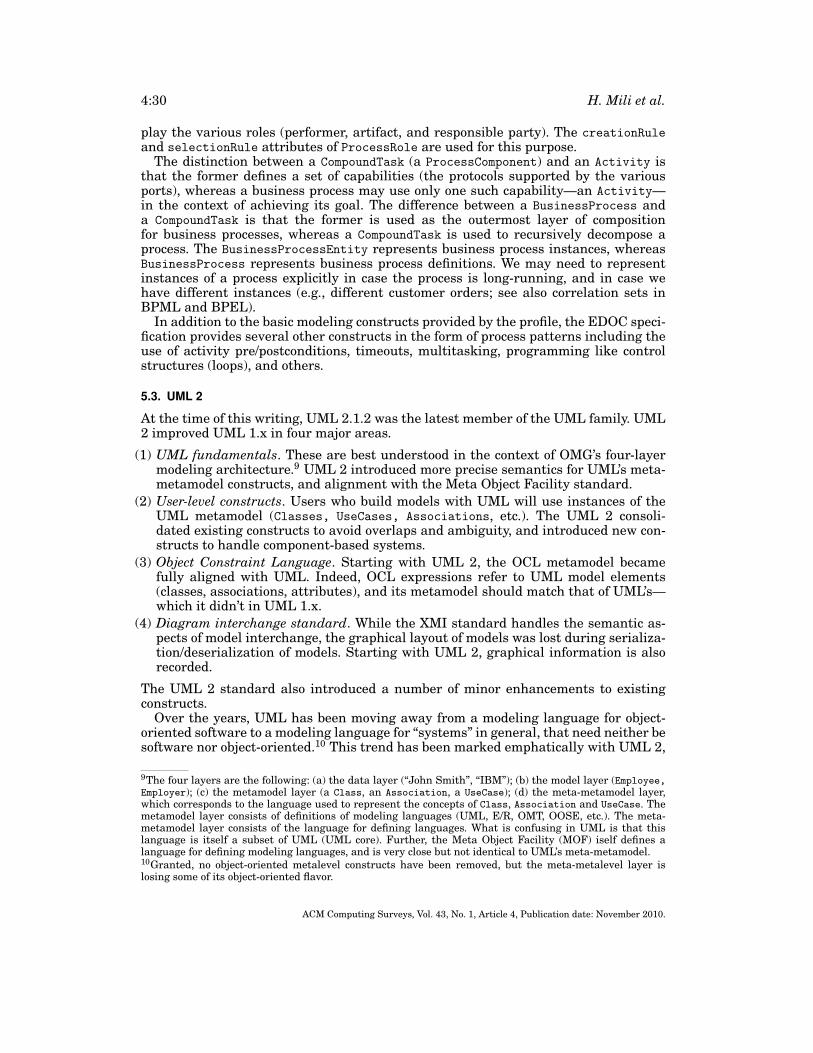
4:30 H. Mili et al.
play the various roles (performer, artifact, and responsible party). The creationRuleand selectionRule attributes of ProcessRole are used for this purpose.
The distinction between a CompoundTask (a ProcessComponent) and an Activity isthat the former defines a set of capabilities (the protocols supported by the variousports), whereas a business process may use only one such capability—an Activity—in the context of achieving its goal. The difference between a BusinessProcess anda CompoundTask is that the former is used as the outermost layer of compositionfor business processes, whereas a CompoundTask is used to recursively decompose aprocess. The BusinessProcessEntity represents business process instances, whereasBusinessProcess represents business process definitions. We may need to representinstances of a process explicitly in case the process is long-running, and in case wehave different instances (e.g., different customer orders; see also correlation sets inBPML and BPEL).
In addition to the basic modeling constructs provided by the profile, the EDOC speci-fication provides several other constructs in the form of process patterns including theuse of activity pre/postconditions, timeouts, multitasking, programming like controlstructures (loops), and others.
5.3. UML 2
At the time of this writing, UML 2.1.2 was the latest member of the UML family. UML2 improved UML 1.x in four major areas.
(1) UML fundamentals. These are best understood in the context of OMG’s four-layermodeling architecture.9 UML 2 introduced more precise semantics for UML’s meta-metamodel constructs, and alignment with the Meta Object Facility standard.
(2) User-level constructs. Users who build models with UML will use instances of theUML metamodel (Classes, UseCases, Associations, etc.). The UML 2 consoli-dated existing constructs to avoid overlaps and ambiguity, and introduced new con-structs to handle component-based systems.
(3) Object Constraint Language. Starting with UML 2, the OCL metamodel becamefully aligned with UML. Indeed, OCL expressions refer to UML model elements(classes, associations, attributes), and its metamodel should match that of UML’s—which it didn’t in UML 1.x.
(4) Diagram interchange standard. While the XMI standard handles the semantic as-pects of model interchange, the graphical layout of models was lost during serializa-tion/deserialization of models. Starting with UML 2, graphical information is alsorecorded.
The UML 2 standard also introduced a number of minor enhancements to existingconstructs.
Over the years, UML has been moving away from a modeling language for object-oriented software to a modeling language for “systems” in general, that need neither besoftware nor object-oriented.10 This trend has been marked emphatically with UML 2,
9The four layers are the following: (a) the data layer (“John Smith”, “IBM”); (b) the model layer (Employee,Employer); (c) the metamodel layer (a Class, an Association, a UseCase); (d) the meta-metamodel layer,which corresponds to the language used to represent the concepts of Class, Association and UseCase. Themetamodel layer consists of definitions of modeling languages (UML, E/R, OMT, OOSE, etc.). The meta-metamodel layer consists of the language for defining languages. What is confusing in UML is that thislanguage is itself a subset of UML (UML core). Further, the Meta Object Facility (MOF) iself defines alanguage for defining modeling languages, and is very close but not identical to UML’s meta-metamodel.10Granted, no object-oriented metalevel constructs have been removed, but the meta-metalevel layer islosing some of its object-oriented flavor.
ACM Computing Surveys, Vol. 43, No. 1, Article 4, Publication date: November 2010.
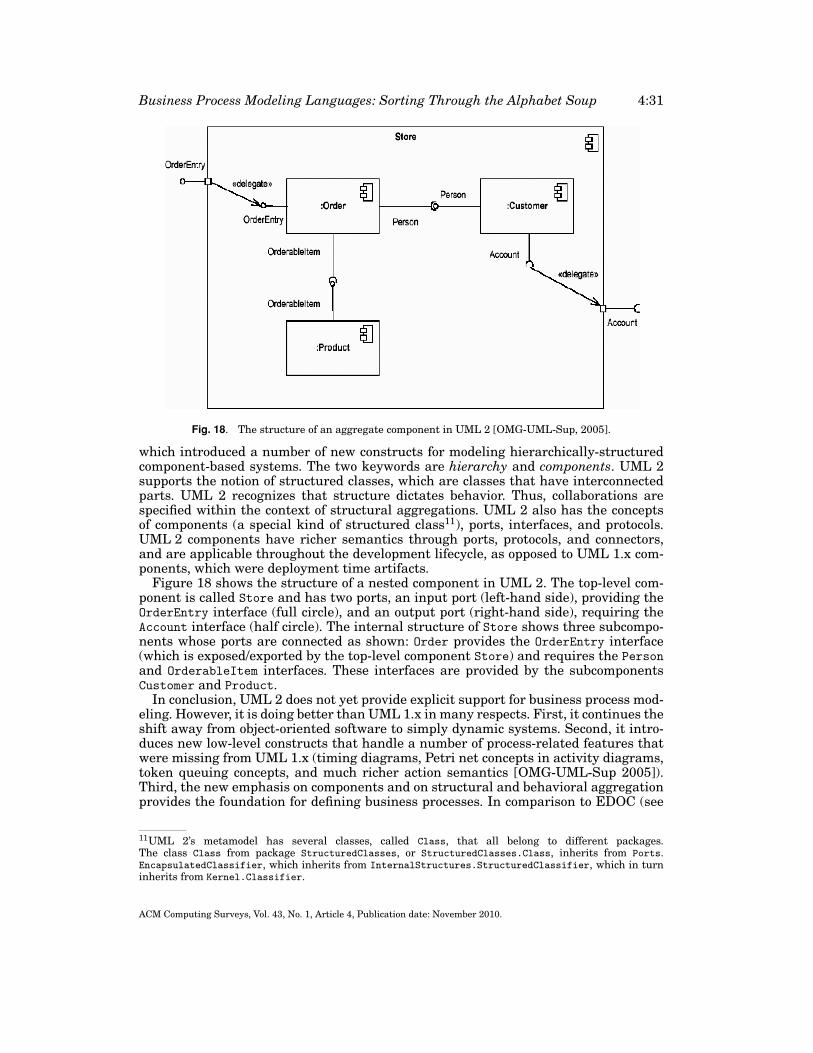
Business Process Modeling Languages: Sorting Through the Alphabet Soup 4:31
Fig. 18. The structure of an aggregate component in UML 2 [OMG-UML-Sup, 2005].
which introduced a number of new constructs for modeling hierarchically-structuredcomponent-based systems. The two keywords are hierarchy and components. UML 2supports the notion of structured classes, which are classes that have interconnectedparts. UML 2 recognizes that structure dictates behavior. Thus, collaborations arespecified within the context of structural aggregations. UML 2 also has the conceptsof components (a special kind of structured class11), ports, interfaces, and protocols.UML 2 components have richer semantics through ports, protocols, and connectors,and are applicable throughout the development lifecycle, as opposed to UML 1.x com-ponents, which were deployment time artifacts.
Figure 18 shows the structure of a nested component in UML 2. The top-level com-ponent is called Store and has two ports, an input port (left-hand side), providing theOrderEntry interface (full circle), and an output port (right-hand side), requiring theAccount interface (half circle). The internal structure of Store shows three subcompo-nents whose ports are connected as shown: Order provides the OrderEntry interface(which is exposed/exported by the top-level component Store) and requires the Personand OrderableItem interfaces. These interfaces are provided by the subcomponentsCustomer and Product.
In conclusion, UML 2 does not yet provide explicit support for business process mod-eling. However, it is doing better than UML 1.x in many respects. First, it continues theshift away from object-oriented software to simply dynamic systems. Second, it intro-duces new low-level constructs that handle a number of process-related features thatwere missing from UML 1.x (timing diagrams, Petri net concepts in activity diagrams,token queuing concepts, and much richer action semantics [OMG-UML-Sup 2005]).Third, the new emphasis on components and on structural and behavioral aggregationprovides the foundation for defining business processes. In comparison to EDOC (see
11UML 2’s metamodel has several classes, called Class, that all belong to different packages.The class Class from package StructuredClasses, or StructuredClasses.Class, inherits from Ports.EncapsulatedClassifier, which inherits from InternalStructures.StructuredClassifier, which in turninherits from Kernel.Classifier.
ACM Computing Surveys, Vol. 43, No. 1, Article 4, Publication date: November 2010.
4:32 H. Mili et al.
5.2), we could say that UML 2 incorporates, as part of the basic UML metamodel, thecontents of EDOC’s Component Collaboration Architecture (CCA) profile, which wasthe basis for the business process profile (see Sections 5.2.2 and 5.2.3). This is a nat-ural evolution: UML remains the rallying point for interesting ideas in modeling, andnewer versions of UML will probably keep integrating extensions developed for earlierones.
6. DYNAMIC PROCESS MODELING LANGUAGES
The languages in this category share at least three characteristics. First, referring toCurtis’s classification [Curtis 1992], they all focus on the dynamic view of businessprocesses. In terms of usage, they cover the full spectrum, from describing businessprocesses for human consumption to enacting/executing business processes. Second,all the languages emphasize a serialization format for model interchange—typicallyin XML. In fact, WS-BPEL is an XML-based textual language. Third, they all repre-sent standardization efforts by industry players. The last language, OMG’s BusinessProcess Definition Metamodel (BPDM), is actually a standard aiming at unifying ex-isting standards! Because the standards build on each other conceptually, they will bepresented in an almost chronological order, with the exception of WS-BPEL which wasactually developed prior to BPMN.
6.1. Workflow Modeling Languages
Etymologically, the term workflow means flow of work, that is, how a complex taskgets done by moving work items (products or documents) through different, often spe-cialized, work stations according to some, often predetermined, sequence. The twoworkflows that often come to mind are assembly line flows in manufacturing, or officeworkflows, whereby office documents are routed between office workers according toa predetermined sequence based on factors such as skills, data dependencies, and au-thority. In both cases, it pays to automate the flow and to monitor its progress [WfMC2002]. In an assembly line, the flow of work is enforced mainly through assembly linedesign that is, the sequencing of machines or work stations, conveyor belts (positionsand pace), input (material) bins, and so on. In an office automation system, a softwareprogram moves electronic documents around between specific functional roles withinthe organization. The past fifteen years have seen increased research interest and aproliferation of software tools for managing workflows that go beyond manufacturingprocesses and administrative (support) processes [Dayal et al. 2001].
The Workflow Management Coalition (WfMC), a coalition of over three hundredmember organizations, including tool vendors, users, service providers, and researchinstitutions, aims at promoting the use of workflow technology through the develop-ment of standards. The WfMC defines workflow as “the computerised facilitation orautomation of a business process, in whole or part” [WfMC 1995]. A workflow man-agement system is defined as “a system that completely defines, manages, and exe-cutes ‘workflows’ through the execution of software whose order of execution is drivenby a computer representation of the workflow logic” [WfMC 1995]. Roughly speaking,a workflow management system automates the flow of work within a business pro-cess. Individual activities within a process may be performed by calling a softwareapplication, or by prompting human actors for input (data or decisions). The WfMCstandardizes five interfaces for dealing with workflow systems [Hollingsworth 1995].Because different tool vendors use different process modeling languages (RAD, EPC,UML, etc.), an important focus of WfMC has been to develop a standard that allowsthe interchange of process descriptions between different tools—”interface 1” in the
ACM Computing Surveys, Vol. 43, No. 1, Article 4, Publication date: November 2010.
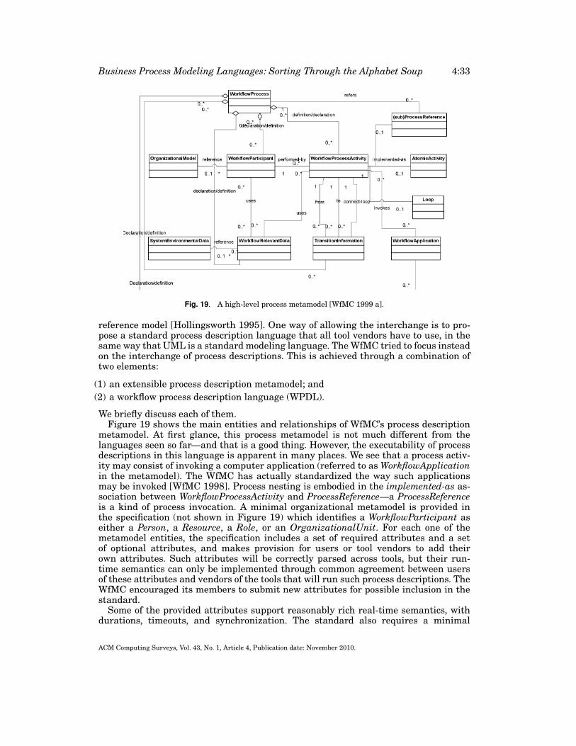
Business Process Modeling Languages: Sorting Through the Alphabet Soup 4:33
Fig. 19. A high-level process metamodel [WfMC 1999 a].
reference model [Hollingsworth 1995]. One way of allowing the interchange is to pro-pose a standard process description language that all tool vendors have to use, in thesame way that UML is a standard modeling language. The WfMC tried to focus insteadon the interchange of process descriptions. This is achieved through a combination oftwo elements:
(1) an extensible process description metamodel; and(2) a workflow process description language (WPDL).
We briefly discuss each of them.Figure 19 shows the main entities and relationships of WfMC’s process description
metamodel. At first glance, this process metamodel is not much different from thelanguages seen so far—and that is a good thing. However, the executability of processdescriptions in this language is apparent in many places. We see that a process activ-ity may consist of invoking a computer application (referred to as WorkflowApplicationin the metamodel). The WfMC has actually standardized the way such applicationsmay be invoked [WfMC 1998]. Process nesting is embodied in the implemented-as as-sociation between WorkflowProcessActivity and ProcessReference—a ProcessReferenceis a kind of process invocation. A minimal organizational metamodel is provided inthe specification (not shown in Figure 19) which identifies a WorkflowParticipant aseither a Person, a Resource, a Role, or an OrganizationalUnit. For each one of themetamodel entities, the specification includes a set of required attributes and a setof optional attributes, and makes provision for users or tool vendors to add theirown attributes. Such attributes will be correctly parsed across tools, but their run-time semantics can only be implemented through common agreement between usersof these attributes and vendors of the tools that will run such process descriptions. TheWfMC encouraged its members to submit new attributes for possible inclusion in thestandard.
Some of the provided attributes support reasonably rich real-time semantics, withdurations, timeouts, and synchronization. The standard also requires a minimal
ACM Computing Surveys, Vol. 43, No. 1, Article 4, Publication date: November 2010.
4:34 H. Mili et al.
state metamodel for workflow process activities: notStarted, running, suspended, andcompleted. Users and tool vendors should, minimally, support these, but may chooseto support other states as well.
The Workflow Process Description Language (WPDL) is a language for “serializing”process models, described according to the process description metamodel shown inFigure 19. It is given as a grammar in Extended Backus-Naur Form (EBNF). An XML-based serialization of WPDL descriptions has been proposed—called XPDL [WfMC2002b]. Subsequent versions of XPDL have actually replaced WPDL. The latest ver-sion of XPDL, XPDL 2.1, was released in April 2008, and is meant as a textual repre-sentation of BPMN diagrams; BPMN is discussed in Section 6.3.
6.2. The Business Process Modeling Language (BPML)
The Business Process Modeling Language “defines a formal model for expressing exe-cutable processes that addresses all aspects of enterprise business processes, includingactivities of varying complexity, transactions and their compensation, data manage-ment, concurrency, exception handling and operational semantics” [BPMI 2003]. TheBPML specification was developed by the Business Process Management Initiative, anindustry organization founded in 2000 to develop standards for business process man-agement, both within and between organizations. The BPML makes extensive use ofXML in two different places.
(1) XML is used as a presentation and serialization format for business process descrip-tions.
(2) XML Schema descriptions (XSD) are used to specify the data types manipulated bythe processes.
We now discuss the main constructs of the BPML.BPML is heavily oriented towards execution, and the reader will find strong
analogies between BPML constructs and common programming language constructs.Roughly speaking, a process is a set of activities executed within a context. An activityis “something to be performed”. BPML comes with a predefined set of fairly low-levelactivities, corresponding to control structures in programming languages.12 From atransactional point of view, activities can be atomic or not. Most simple activities areatomic, and complex activities are, by default, nonatomic. The context of an activityis its execution context. It is characterized by the set of properties that are specific tothat activity (local variables, exceptions, internal functions/processes, etc.). The closestthing in programming terms is the stack/call frame for a function. A process is, in turn,a complex activity that defines its own execution context. The closest thing, in pro-gramming terms, is a function or a procedure. Some processes are visible everywhere,others are local to other processes. Processes can be triggered in one of two ways: (1)through an explicit call from another process or activity; or (2) through an event. Pro-cesses have input/output parameters. These parameters are read from, and writteninto, the properties of their enclosing execution context. Properties are variables thatare local to a context. We can specify a type, a default value, and an expression for as-signing them a value. The type can be any valid XML Schema, including simple types,complex types, derived types, as well as anonymous types defined through elementdeclarations.
BPML has a handful of high-level constructs that are not typically found in pro-gramming languages, such as the notions of schedules, transactions, compensation,and correlation properties. A schedule is a series of time events. We can associate a
12There are seventeen activities including Assign, Call, Foreach, Sequence, Until, While, Synch and Switch.
ACM Computing Surveys, Vol. 43, No. 1, Article 4, Publication date: November 2010.
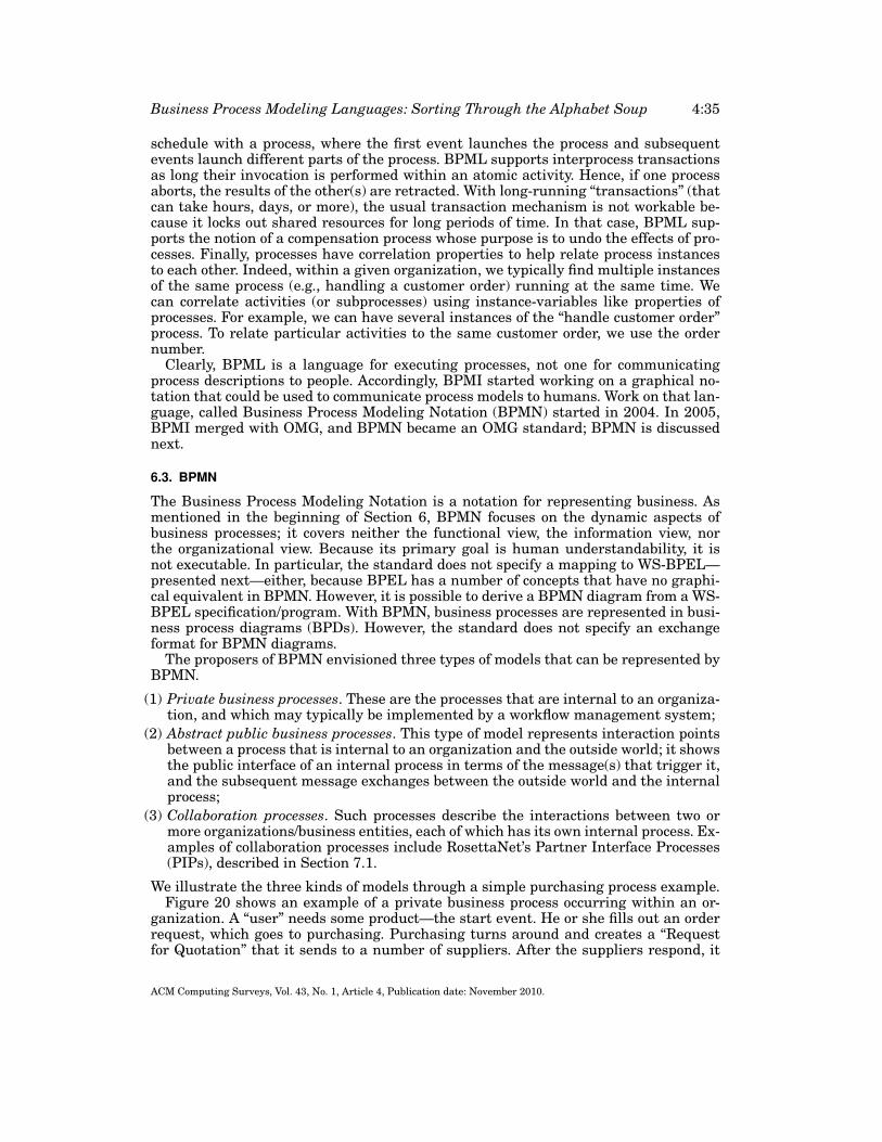
Business Process Modeling Languages: Sorting Through the Alphabet Soup 4:35
schedule with a process, where the first event launches the process and subsequentevents launch different parts of the process. BPML supports interprocess transactionsas long their invocation is performed within an atomic activity. Hence, if one processaborts, the results of the other(s) are retracted. With long-running “transactions” (thatcan take hours, days, or more), the usual transaction mechanism is not workable be-cause it locks out shared resources for long periods of time. In that case, BPML sup-ports the notion of a compensation process whose purpose is to undo the effects of pro-cesses. Finally, processes have correlation properties to help relate process instancesto each other. Indeed, within a given organization, we typically find multiple instancesof the same process (e.g., handling a customer order) running at the same time. Wecan correlate activities (or subprocesses) using instance-variables like properties ofprocesses. For example, we can have several instances of the “handle customer order”process. To relate particular activities to the same customer order, we use the ordernumber.
Clearly, BPML is a language for executing processes, not one for communicatingprocess descriptions to people. Accordingly, BPMI started working on a graphical no-tation that could be used to communicate process models to humans. Work on that lan-guage, called Business Process Modeling Notation (BPMN) started in 2004. In 2005,BPMI merged with OMG, and BPMN became an OMG standard; BPMN is discussednext.
6.3. BPMN
The Business Process Modeling Notation is a notation for representing business. Asmentioned in the beginning of Section 6, BPMN focuses on the dynamic aspects ofbusiness processes; it covers neither the functional view, the information view, northe organizational view. Because its primary goal is human understandability, it isnot executable. In particular, the standard does not specify a mapping to WS-BPEL—presented next—either, because BPEL has a number of concepts that have no graphi-cal equivalent in BPMN. However, it is possible to derive a BPMN diagram from a WS-BPEL specification/program. With BPMN, business processes are represented in busi-ness process diagrams (BPDs). However, the standard does not specify an exchangeformat for BPMN diagrams.
The proposers of BPMN envisioned three types of models that can be represented byBPMN.
(1) Private business processes. These are the processes that are internal to an organiza-tion, and which may typically be implemented by a workflow management system;
(2) Abstract public business processes. This type of model represents interaction pointsbetween a process that is internal to an organization and the outside world; it showsthe public interface of an internal process in terms of the message(s) that trigger it,and the subsequent message exchanges between the outside world and the internalprocess;
(3) Collaboration processes. Such processes describe the interactions between two ormore organizations/business entities, each of which has its own internal process. Ex-amples of collaboration processes include RosettaNet’s Partner Interface Processes(PIPs), described in Section 7.1.
We illustrate the three kinds of models through a simple purchasing process example.Figure 20 shows an example of a private business process occurring within an or-
ganization. A “user” needs some product—the start event. He or she fills out an orderrequest, which goes to purchasing. Purchasing turns around and creates a “Requestfor Quotation” that it sends to a number of suppliers. After the suppliers respond, it
ACM Computing Surveys, Vol. 43, No. 1, Article 4, Publication date: November 2010.
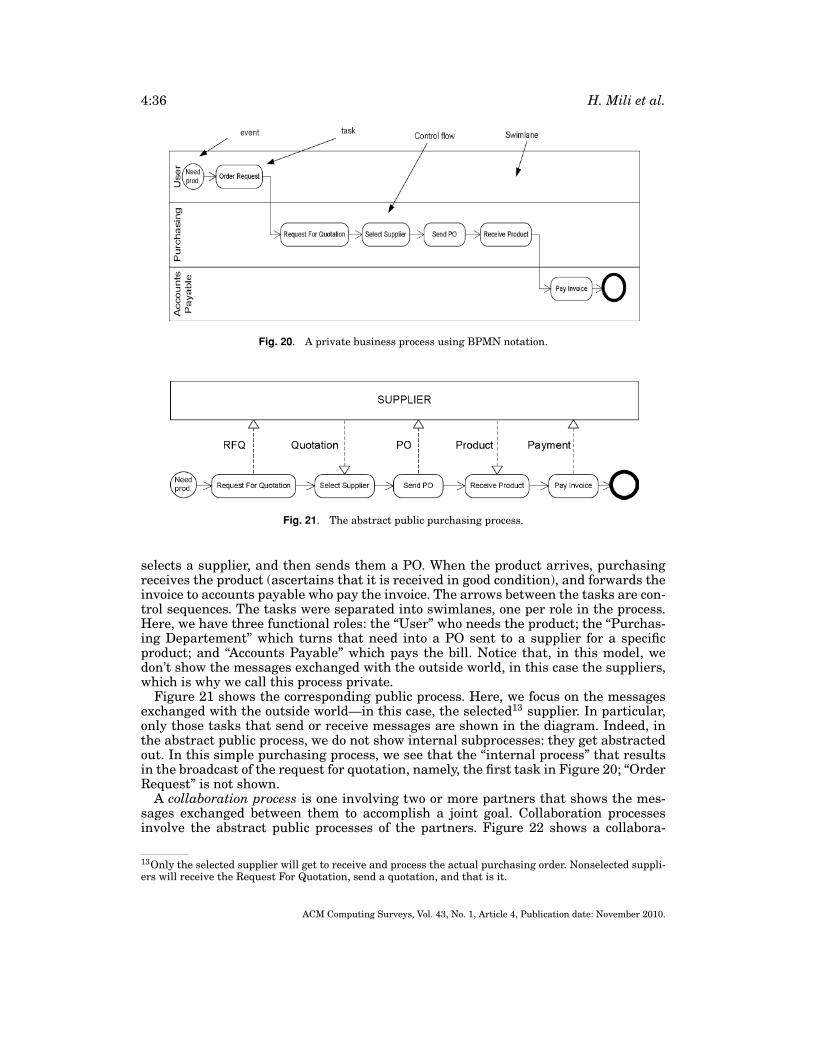
4:36 H. Mili et al.
Fig. 20. A private business process using BPMN notation.
Fig. 21. The abstract public purchasing process.
selects a supplier, and then sends them a PO. When the product arrives, purchasingreceives the product (ascertains that it is received in good condition), and forwards theinvoice to accounts payable who pay the invoice. The arrows between the tasks are con-trol sequences. The tasks were separated into swimlanes, one per role in the process.Here, we have three functional roles: the “User” who needs the product; the “Purchas-ing Departement” which turns that need into a PO sent to a supplier for a specificproduct; and “Accounts Payable” which pays the bill. Notice that, in this model, wedon’t show the messages exchanged with the outside world, in this case the suppliers,which is why we call this process private.
Figure 21 shows the corresponding public process. Here, we focus on the messagesexchanged with the outside world—in this case, the selected13 supplier. In particular,only those tasks that send or receive messages are shown in the diagram. Indeed, inthe abstract public process, we do not show internal subprocesses: they get abstractedout. In this simple purchasing process, we see that the “internal process” that resultsin the broadcast of the request for quotation, namely, the first task in Figure 20; “OrderRequest” is not shown.
A collaboration process is one involving two or more partners that shows the mes-sages exchanged between them to accomplish a joint goal. Collaboration processesinvolve the abstract public processes of the partners. Figure 22 shows a collabora-
13Only the selected supplier will get to receive and process the actual purchasing order. Nonselected suppli-ers will receive the Request For Quotation, send a quotation, and that is it.
ACM Computing Surveys, Vol. 43, No. 1, Article 4, Publication date: November 2010.
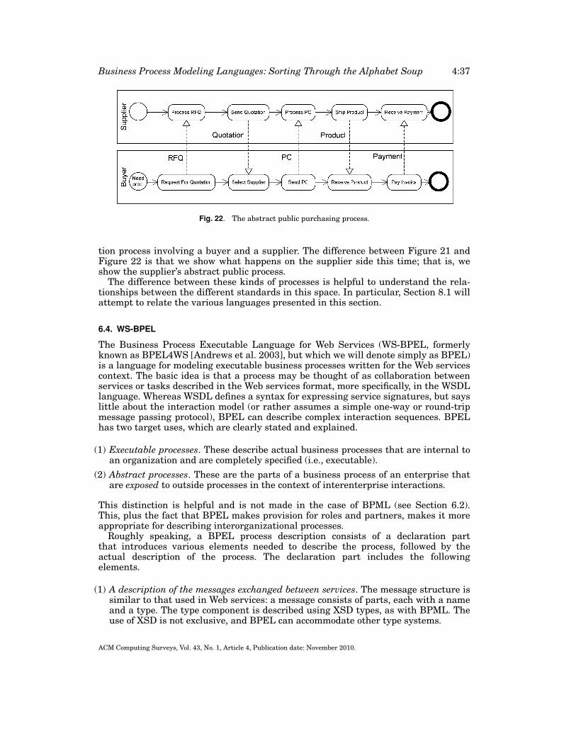
Business Process Modeling Languages: Sorting Through the Alphabet Soup 4:37
Fig. 22. The abstract public purchasing process.
tion process involving a buyer and a supplier. The difference between Figure 21 andFigure 22 is that we show what happens on the supplier side this time; that is, weshow the supplier’s abstract public process.
The difference between these kinds of processes is helpful to understand the rela-tionships between the different standards in this space. In particular, Section 8.1 willattempt to relate the various languages presented in this section.
6.4. WS-BPEL
The Business Process Executable Language for Web Services (WS-BPEL, formerlyknown as BPEL4WS [Andrews et al. 2003], but which we will denote simply as BPEL)is a language for modeling executable business processes written for the Web servicescontext. The basic idea is that a process may be thought of as collaboration betweenservices or tasks described in the Web services format, more specifically, in the WSDLlanguage. Whereas WSDL defines a syntax for expressing service signatures, but sayslittle about the interaction model (or rather assumes a simple one-way or round-tripmessage passing protocol), BPEL can describe complex interaction sequences. BPELhas two target uses, which are clearly stated and explained.
(1) Executable processes. These describe actual business processes that are internal toan organization and are completely specified (i.e., executable).
(2) Abstract processes. These are the parts of a business process of an enterprise thatare exposed to outside processes in the context of interenterprise interactions.
This distinction is helpful and is not made in the case of BPML (see Section 6.2).This, plus the fact that BPEL makes provision for roles and partners, makes it moreappropriate for describing interorganizational processes.
Roughly speaking, a BPEL process description consists of a declaration partthat introduces various elements needed to describe the process, followed by theactual description of the process. The declaration part includes the followingelements.
(1) A description of the messages exchanged between services. The message structure issimilar to that used in Web services: a message consists of parts, each with a nameand a type. The type component is described using XSD types, as with BPML. Theuse of XSD is not exclusive, and BPEL can accommodate other type systems.
ACM Computing Surveys, Vol. 43, No. 1, Article 4, Publication date: November 2010.
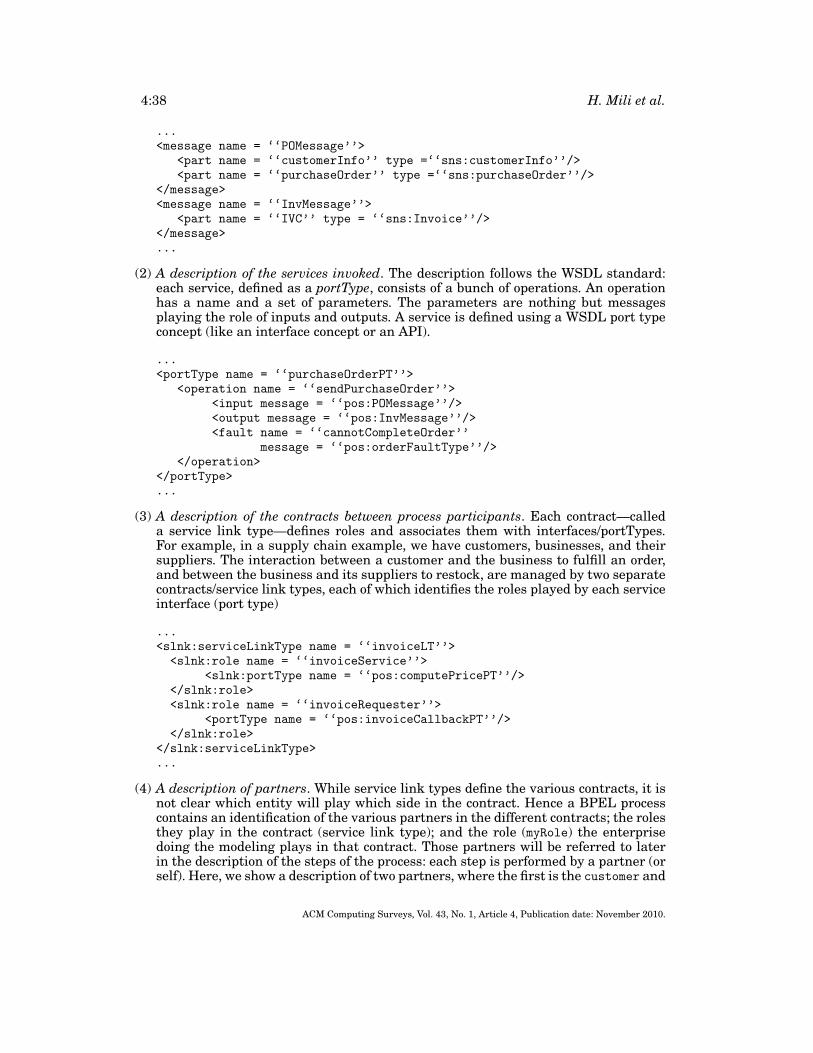
4:38 H. Mili et al.
...<message name = ‘‘POMessage’’>
<part name = ‘‘customerInfo’’ type =‘‘sns:customerInfo’’/><part name = ‘‘purchaseOrder’’ type =‘‘sns:purchaseOrder’’/>
</message><message name = ‘‘InvMessage’’>
<part name = ‘‘IVC’’ type = ‘‘sns:Invoice’’/></message>...
(2) A description of the services invoked. The description follows the WSDL standard:each service, defined as a portType, consists of a bunch of operations. An operationhas a name and a set of parameters. The parameters are nothing but messagesplaying the role of inputs and outputs. A service is defined using a WSDL port typeconcept (like an interface concept or an API).
...<portType name = ‘‘purchaseOrderPT’’>
<operation name = ‘‘sendPurchaseOrder’’><input message = ‘‘pos:POMessage’’/><output message = ‘‘pos:InvMessage’’/><fault name = ‘‘cannotCompleteOrder’’
message = ‘‘pos:orderFaultType’’/></operation>
</portType>...
(3) A description of the contracts between process participants. Each contract—calleda service link type—defines roles and associates them with interfaces/portTypes.For example, in a supply chain example, we have customers, businesses, and theirsuppliers. The interaction between a customer and the business to fulfill an order,and between the business and its suppliers to restock, are managed by two separatecontracts/service link types, each of which identifies the roles played by each serviceinterface (port type)
...<slnk:serviceLinkType name = ‘‘invoiceLT’’><slnk:role name = ‘‘invoiceService’’>
<slnk:portType name = ‘‘pos:computePricePT’’/></slnk:role><slnk:role name = ‘‘invoiceRequester’’>
<portType name = ‘‘pos:invoiceCallbackPT’’/></slnk:role>
</slnk:serviceLinkType>...
(4) A description of partners. While service link types define the various contracts, it isnot clear which entity will play which side in the contract. Hence a BPEL processcontains an identification of the various partners in the different contracts; the rolesthey play in the contract (service link type); and the role (myRole) the enterprisedoing the modeling plays in that contract. Those partners will be referred to laterin the description of the steps of the process: each step is performed by a partner (orself). Here, we show a description of two partners, where the first is the customer and
ACM Computing Surveys, Vol. 43, No. 1, Article 4, Publication date: November 2010.
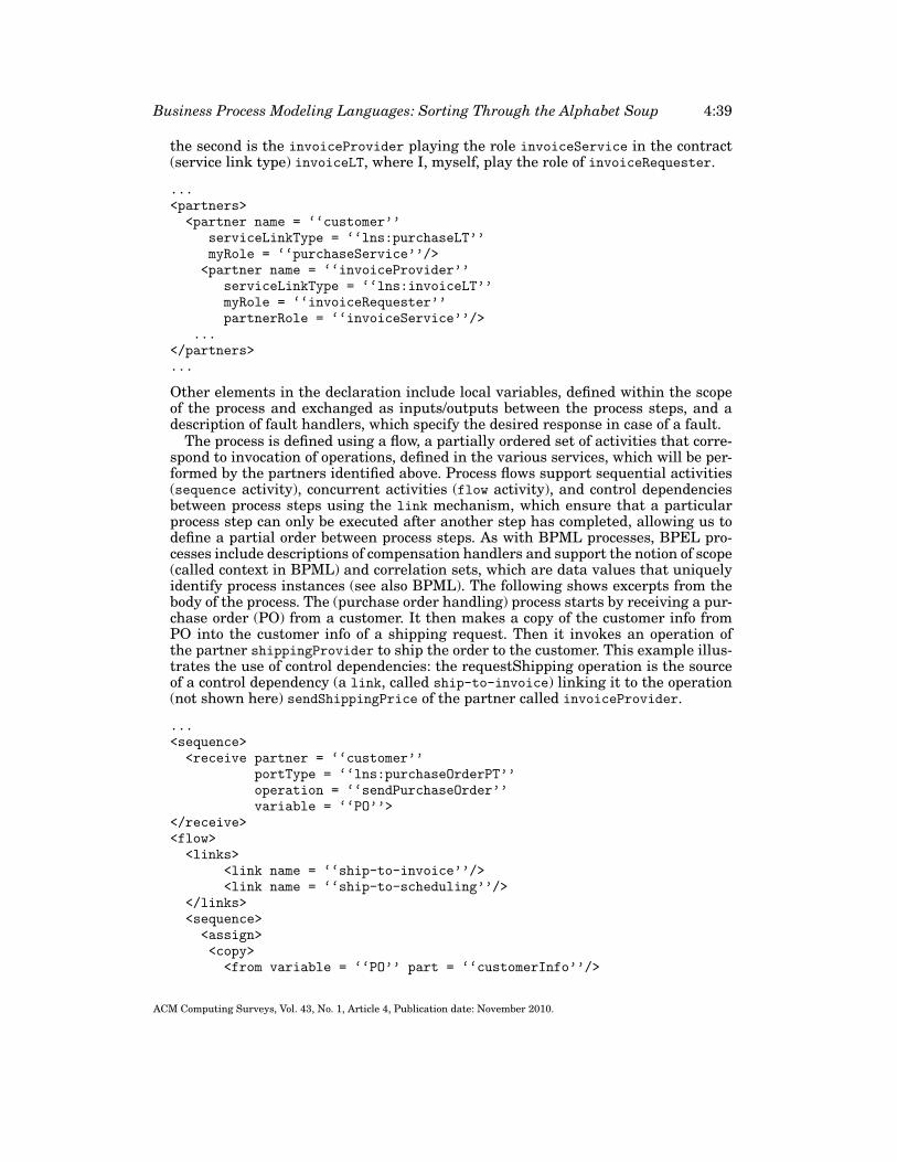
Business Process Modeling Languages: Sorting Through the Alphabet Soup 4:39
the second is the invoiceProvider playing the role invoiceService in the contract(service link type) invoiceLT, where I, myself, play the role of invoiceRequester.
...<partners><partner name = ‘‘customer’’
serviceLinkType = ‘‘lns:purchaseLT’’myRole = ‘‘purchaseService’’/>
<partner name = ‘‘invoiceProvider’’serviceLinkType = ‘‘lns:invoiceLT’’myRole = ‘‘invoiceRequester’’partnerRole = ‘‘invoiceService’’/>
...</partners>...
Other elements in the declaration include local variables, defined within the scopeof the process and exchanged as inputs/outputs between the process steps, and adescription of fault handlers, which specify the desired response in case of a fault.
The process is defined using a flow, a partially ordered set of activities that corre-spond to invocation of operations, defined in the various services, which will be per-formed by the partners identified above. Process flows support sequential activities(sequence activity), concurrent activities (flow activity), and control dependenciesbetween process steps using the link mechanism, which ensure that a particularprocess step can only be executed after another step has completed, allowing us todefine a partial order between process steps. As with BPML processes, BPEL pro-cesses include descriptions of compensation handlers and support the notion of scope(called context in BPML) and correlation sets, which are data values that uniquelyidentify process instances (see also BPML). The following shows excerpts from thebody of the process. The (purchase order handling) process starts by receiving a pur-chase order (PO) from a customer. It then makes a copy of the customer info fromPO into the customer info of a shipping request. Then it invokes an operation ofthe partner shippingProvider to ship the order to the customer. This example illus-trates the use of control dependencies: the requestShipping operation is the sourceof a control dependency (a link, called ship-to-invoice) linking it to the operation(not shown here) sendShippingPrice of the partner called invoiceProvider.
...<sequence><receive partner = ‘‘customer’’
portType = ‘‘lns:purchaseOrderPT’’operation = ‘‘sendPurchaseOrder’’variable = ‘‘PO’’>
</receive><flow><links>
<link name = ‘‘ship-to-invoice’’/><link name = ‘‘ship-to-scheduling’’/>
</links><sequence><assign><copy><from variable = ‘‘PO’’ part = ‘‘customerInfo’’/>
ACM Computing Surveys, Vol. 43, No. 1, Article 4, Publication date: November 2010.
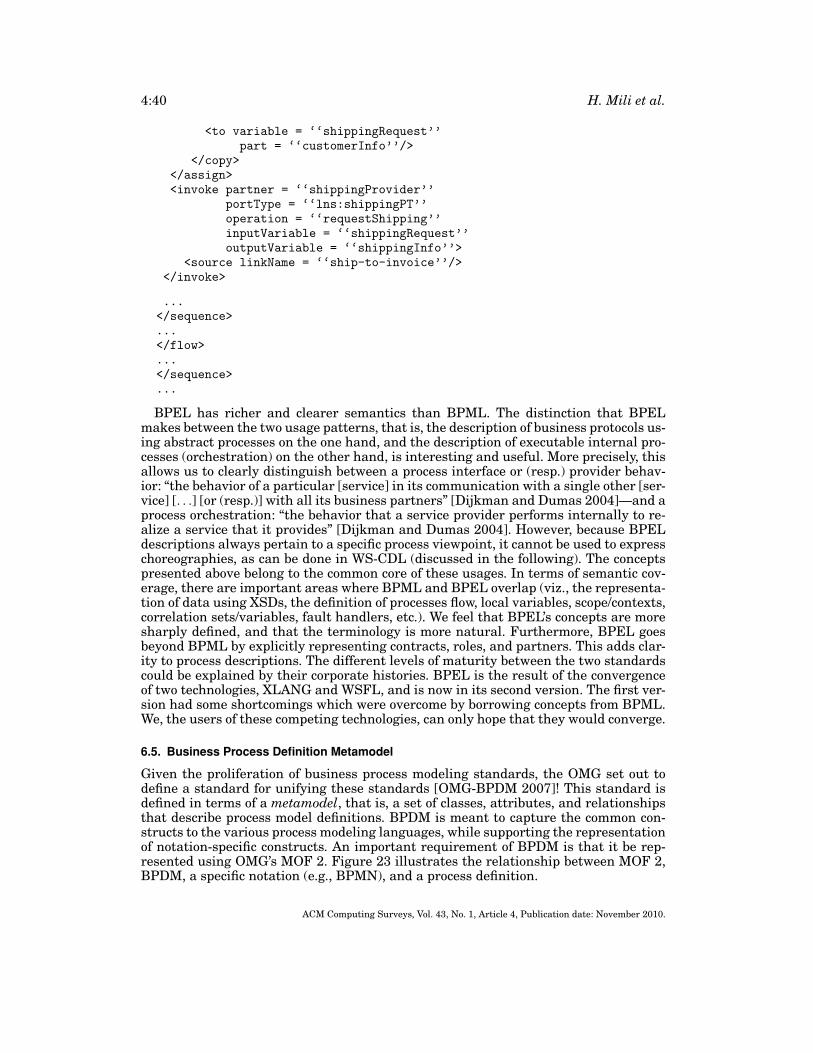
4:40 H. Mili et al.
<to variable = ‘‘shippingRequest’’part = ‘‘customerInfo’’/>
</copy></assign><invoke partner = ‘‘shippingProvider’’
portType = ‘‘lns:shippingPT’’operation = ‘‘requestShipping’’inputVariable = ‘‘shippingRequest’’outputVariable = ‘‘shippingInfo’’>
<source linkName = ‘‘ship-to-invoice’’/></invoke>
...</sequence>...</flow>...</sequence>...
BPEL has richer and clearer semantics than BPML. The distinction that BPELmakes between the two usage patterns, that is, the description of business protocols us-ing abstract processes on the one hand, and the description of executable internal pro-cesses (orchestration) on the other hand, is interesting and useful. More precisely, thisallows us to clearly distinguish between a process interface or (resp.) provider behav-ior: “the behavior of a particular [service] in its communication with a single other [ser-vice] [. . .] [or (resp.)] with all its business partners” [Dijkman and Dumas 2004]—and aprocess orchestration: “the behavior that a service provider performs internally to re-alize a service that it provides” [Dijkman and Dumas 2004]. However, because BPELdescriptions always pertain to a specific process viewpoint, it cannot be used to expresschoreographies, as can be done in WS-CDL (discussed in the following). The conceptspresented above belong to the common core of these usages. In terms of semantic cov-erage, there are important areas where BPML and BPEL overlap (viz., the representa-tion of data using XSDs, the definition of processes flow, local variables, scope/contexts,correlation sets/variables, fault handlers, etc.). We feel that BPEL’s concepts are moresharply defined, and that the terminology is more natural. Furthermore, BPEL goesbeyond BPML by explicitly representing contracts, roles, and partners. This adds clar-ity to process descriptions. The different levels of maturity between the two standardscould be explained by their corporate histories. BPEL is the result of the convergenceof two technologies, XLANG and WSFL, and is now in its second version. The first ver-sion had some shortcomings which were overcome by borrowing concepts from BPML.We, the users of these competing technologies, can only hope that they would converge.
6.5. Business Process Definition Metamodel
Given the proliferation of business process modeling standards, the OMG set out todefine a standard for unifying these standards [OMG-BPDM 2007]! This standard isdefined in terms of a metamodel, that is, a set of classes, attributes, and relationshipsthat describe process model definitions. BPDM is meant to capture the common con-structs to the various process modeling languages, while supporting the representationof notation-specific constructs. An important requirement of BPDM is that it be rep-resented using OMG’s MOF 2. Figure 23 illustrates the relationship between MOF 2,BPDM, a specific notation (e.g., BPMN), and a process definition.
ACM Computing Surveys, Vol. 43, No. 1, Article 4, Publication date: November 2010.
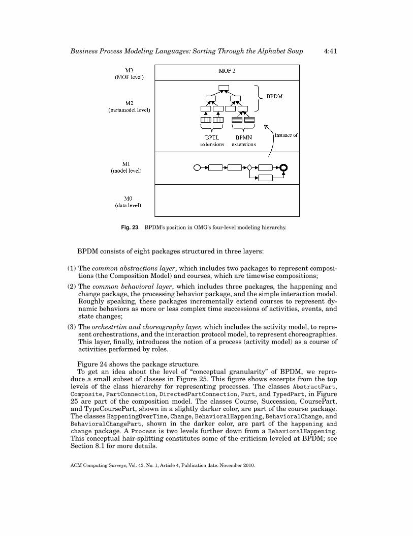
Business Process Modeling Languages: Sorting Through the Alphabet Soup 4:41
Fig. 23. BPDM’s position in OMG’s four-level modeling hierarchy.
BPDM consists of eight packages structured in three layers:
(1) The common abstractions layer, which includes two packages to represent composi-tions (the Composition Model) and courses, which are timewise compositions;
(2) The common behavioral layer, which includes three packages, the happening andchange package, the processing behavior package, and the simple interaction model.Roughly speaking, these packages incrementally extend courses to represent dy-namic behaviors as more or less complex time successions of activities, events, andstate changes;
(3) The orchestrtim and choreography layer, which includes the activity model, to repre-sent orchestrations, and the interaction protocol model, to represent choreographies.This layer, finally, introduces the notion of a process (activity model) as a course ofactivities performed by roles.
Figure 24 shows the package structure.To get an idea about the level of “conceptual granularity” of BPDM, we repro-
duce a small subset of classes in Figure 25. This figure shows excerpts from the toplevels of the class hierarchy for representing processes. The classes AbstractPart,Composite, PartConnection, DirectedPartConnection, Part, and TypedPart, in Figure25 are part of the composition model. The classes Course, Succession, CoursePart,and TypeCoursePart, shown in a slightly darker color, are part of the course package.The classes HappeningOverTime, Change, BehavioralHappening, BehavioralChange, andBehavioralChangePart, shown in the darker color, are part of the happening andchange package. A Process is two levels further down from a BehavioralHappening.This conceptual hair-splitting constitutes some of the criticism leveled at BPDM; seeSection 8.1 for more details.
ACM Computing Surveys, Vol. 43, No. 1, Article 4, Publication date: November 2010.
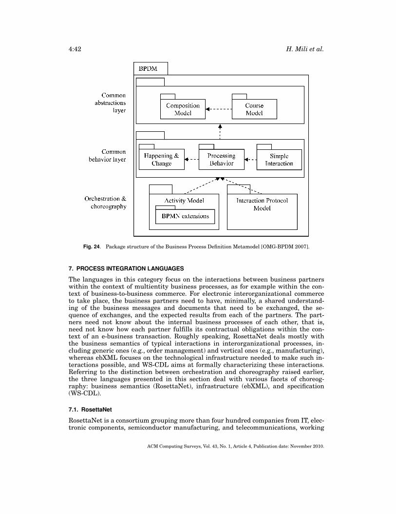
4:42 H. Mili et al.
Fig. 24. Package structure of the Business Process Definition Metamodel [OMG-BPDM 2007].
7. PROCESS INTEGRATION LANGUAGES
The languages in this category focus on the interactions between business partnerswithin the context of multientity business processes, as for example within the con-text of business-to-business commerce. For electronic interorganizational commerceto take place, the business partners need to have, minimally, a shared understand-ing of the business messages and documents that need to be exchanged, the se-quence of exchanges, and the expected results from each of the partners. The part-ners need not know about the internal business processes of each other, that is,need not know how each partner fulfills its contractual obligations within the con-text of an e-business transaction. Roughly speaking, RosettaNet deals mostly withthe business semantics of typical interactions in interorganizational processes, in-cluding generic ones (e.g., order management) and vertical ones (e.g., manufacturing),whereas ebXML focuses on the technological infrastructure needed to make such in-teractions possible, and WS-CDL aims at formally characterizing these interactions.Referring to the distinction between orchestration and choreography raised earlier,the three languages presented in this section deal with various facets of choreog-raphy: business semantics (RosettaNet), infrastructure (ebXML), and specification(WS-CDL).
7.1. RosettaNet
RosettaNet is a consortium grouping more than four hundred companies from IT, elec-tronic components, semiconductor manufacturing, and telecommunications, working
ACM Computing Surveys, Vol. 43, No. 1, Article 4, Publication date: November 2010.
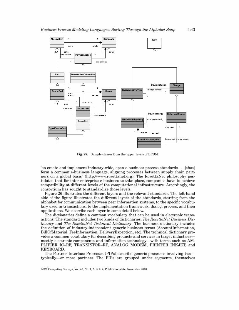
Business Process Modeling Languages: Sorting Through the Alphabet Soup 4:43
Fig. 25. Sample classes from the upper levels of BPDM.
“to create and implement industry-wide, open e-business process standards . . . [that]form a common e-business language, aligning processes between supply chain part-ners on a global basis” (http://www.rosettanet.org). The RosettaNet philosophy pos-tulates that for inter-enterprise e-business to take place, companies have to achievecompatibility at different levels of the computational infrastructure. Accordingly, theconsortium has sought to standardize those levels.
Figure 26 illustrates the different layers and the relevant standards. The left-handside of the figure illustrates the different layers of the standards, starting from thealphabet for communication between peer information systems, to the specific vocabu-lary used in transactions, to the implementation framework, dialog, process, and thenapplications. We describe each layer in some detail below.
The dictionaries define a common vocabulary that can be used in electronic trans-actions. The standard includes two kinds of dictionaries, The RosettaNet Business Dic-tionary and The RosettaNet Technical Dictionary. The business dictionary includesthe definition of industry-independent generic business terms (AccountInformation,BillOfMaterial, FeeInformation, DeliveryException, etc). The technical dictionary pro-vides a common vocabulary for describing products and services in target industries—mostly electronic components and information technology—with terms such as AM-PLIFIER IC–RF, TRANSISTOR–RF, ANALOG MODEM, PRINTER INKJET, andKEYBOARD.
The Partner Interface Processes (PIPs) describe generic processes involving two—typically—or more partners. The PIPs are grouped under segments, themselves
ACM Computing Surveys, Vol. 43, No. 1, Article 4, Publication date: November 2010.
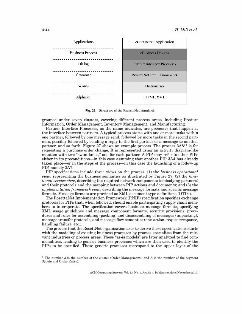
4:44 H. Mili et al.
Fig. 26. Structure of the RosettaNet standard.
grouped under seven clusters, covering different process areas, including ProductInformation, Order Management, Inventory Management, and Manufacturing.
Partner Interface Processes, as the name indicates, are processes that happen atthe interface between partners. A typical process starts with one or more tasks withinone partner, followed by one message send, followed by more tasks in the second part-ners, possibly followed by sending a reply to the first partner or a message to anotherpartner, and so forth. Figure 27 shows an example process. The process 3A814 is forrequesting a purchase order change. It is represented using an activity diagram-likenotation with two “swim lanes,” one for each partner. A PIP may refer to other PIPseither in its preconditions—in this case assuming that another PIP 3A4 has alreadytaken place—or in the steps of the process—in this case the launching of a follow-upPIP, namely 3A7.
PIP specifications include three views on the process: (1) the business operationalview, representing the business semantics as illustrated by Figure 27; (2) the func-tional service view, describing the required network components (embodying partners)and their protocols and the mapping between PIP actions and documents; and (3) theimplementation framework view, describing the message formats and specific messageformats. Message formats are provided as XML document type definitions (DTDs).
The RosettaNet Implementation Framework (RNIF) specification specifies exchangeprotocols for PIPs that, when followed, should enable participating supply chain mem-bers to interoperate. The specification covers business message formats, specifyingXML usage guidelines and message component formats, security provisions, proce-dures and rules for assembling (packing) and disassembling of messages (unpacking),message transfer protocols, and message flow semantics (one-action, request/response,handling failure, etc.).
The process that the RosettNet organization uses to derive these specifications startswith the modeling of existing business processes by process specialists from the rele-vant industries or process areas. These “as-is models” are later analyzed to find com-monalities, leading to generic business processes which are then used to identify thePIPs to be specified. Those generic processes correspond to the upper layer of the
14The number 3 is the number of the cluster (Order Management), and A is the number of the segment(Quote and Order Entry).
ACM Computing Surveys, Vol. 43, No. 1, Article 4, Publication date: November 2010.
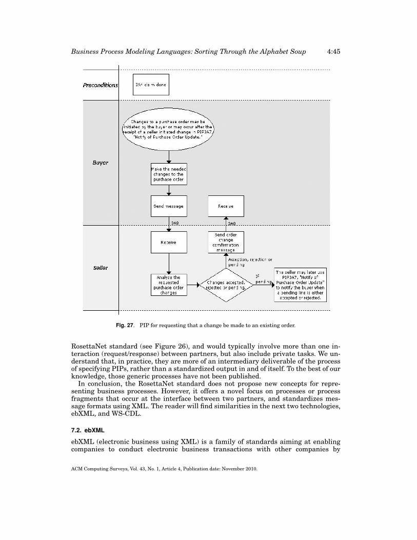
Business Process Modeling Languages: Sorting Through the Alphabet Soup 4:45
Fig. 27. PIP for requesting that a change be made to an existing order.
RosettaNet standard (see Figure 26), and would typically involve more than one in-teraction (request/response) between partners, but also include private tasks. We un-derstand that, in practice, they are more of an intermediary deliverable of the processof specifying PIPs, rather than a standardized output in and of itself. To the best of ourknowledge, those generic processes have not been published.
In conclusion, the RosettaNet standard does not propose new concepts for repre-senting business processes. However, it offers a novel focus on processes or processfragments that occur at the interface between two partners, and standardizes mes-sage formats using XML. The reader will find similarities in the next two technologies,ebXML, and WS-CDL.
7.2. ebXML
ebXML (electronic business using XML) is a family of standards aiming at enablingcompanies to conduct electronic business transactions with other companies by
ACM Computing Surveys, Vol. 43, No. 1, Article 4, Publication date: November 2010.
4:46 H. Mili et al.
exchanging XML documents over the internet. ebXML is sponsored by the UnitedNations’ Center for Trade Facilitation and Electronic Business (UN/CEFACT,www.unece.org/cefact) and the Organization for the Advancement of StructuredInformation Standards15 (OASIS, www.oasis-open.org), a nonprofit organizationgrouping over six hundred members (corporate and individuals) worldwide. At firstglance, the goals of the ebXML standard seem to overlap considerably with thoseof RosettaNet—and Web services, for that matter. However, the focus of the twotechnologies is different. Whereas RosettaNet focuses on the business semantics ofinter-enterprise process integration, with its dictionaries and PIPs. ebXML focuses onthe integration process and on the support infrastructure. The differences will becomeclearer as we present the key elements of ebXML.
Roughly speaking, the ebXML family of standards addresses the following areas:
(1) a standard mechanism (and language) for describing business processes and theirassociated information (the Business Process Specification Schema [ebXML 2001a]);
(2) a standard mechanism through which enterprises describe the business processesthey support, and how they support them (API, message format, communicationprotocol, etc.), that is, the Collaboration Protocol Profile (CPP, [ebXML, 2001b]);
(3) a standard mechanism for registering and querying CPPs through a publicly acces-sible registry (the ebXML Registry Services [ebXML 2001c]);
(4) a standard mechanism for matching two CPPs to produce Collaboration ProtocolAgreements (CPA, [ebXML 2001b]);
(5) a library containing a set of core business processes and supporting documents(business messages) that cover the most common business scenarios.
Figure 28 illustrates a business scenario involving two companies A and B that enterinto an electronic business transaction under the ebXML framework.
Companies register their collaboration protocol profiles (CPP), which describe theirbusiness processes and the way they are supported (communication protocol, messageformat, API, etc.). The ebXML registry enables companies, say company A, to registerCPPs and to search for them using different query formats [ebXML, 2001 c]. A com-pany B can query the registry for CPPs that satisfy certain criteria (step 2). Such crite-ria include: (i) offering a given service; (ii) offering it competitively; and (iii) providinga workable way of invoking it. Once company B finds a CPP that matches those crite-ria, it enters into negotiations with the provider (company A) regarding the business(price, availability), the operational (which specific process variant to use), and tech-nical parameters of the transaction (step 3). A collaboration profile agreement (CPA)represents that agreement. Once the agreement is in place, it is implemented on bothsides, and business transactions can start (step 4).
To ensure that the business processes of the potential business partners are inter-operable, it is not sufficient to specify them using the same notation (BPSS, see ebXML2001a]). We have to strive towards standardizing the processes themselves, or failingthat, to build processes using a set of reusable business process fragments and busi-ness documents. Those business process fragments and business documents constitutethe core library, which is made accessible through the ebXML registry so that compa-nies may retrieve them to build and document their own processes. Referring to Figure28, in practice, company A would have built its CPPs by first consulting the ebXMLregistry for reusable processes and documents.
15OASIS, which was founded in 1993 under the name SGML open, was initially concerned with SGMLstandards. In 1998, it broadened its scope and changed its name.
ACM Computing Surveys, Vol. 43, No. 1, Article 4, Publication date: November 2010.
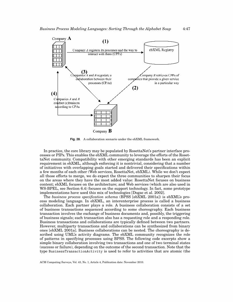
Business Process Modeling Languages: Sorting Through the Alphabet Soup 4:47
Fig. 28. A collaboration scenario under the ebXML framework.
In practice, the core library may be populated by RosettaNet’s partner interface pro-cesses or PIPs. This enables the ebXML community to leverage the efforts of the Roset-taNet community. Compatibility with other emerging standards has been an explicitrequirement in ebXML, although enforcing it is nontrivial, considering that a numberof initiatives with overlapping goals started and delivered their specifications withina few months of each other (Web services, RosettaNet, ebXML). While we don’t expectall those efforts to merge, we do expect the three communities to sharpen their focuson the areas where they have the most added value: RosettaNet focuses on businesscontent; ebXML focuses on the architecture; and Web services (which are also used inWS-BPEL, see Section 6.4) focuses on the support technology. In fact, some prototypeimplementations have used this mix of technologies [Dogac et al. 2002].
The business process specification schema (BPSS [ebXML 2001a]) is ebXML’s pro-cess modeling language. In ebXML, an interenterprise process is called a businesscollaboration. Each partner plays a role. A business collaboration consists of a setof business transactions sequenced according to some choreography. Each businesstransaction involves the exchange of business documents and, possibly, the triggeringof business signals; each transaction also has a requesting role and a responding role.Business transactions and collaborations are typically defined between two partners.However, multiparty transactions and collaborations can be synthesized from binaryones [ebXML 2001a]. Business collaborations can be nested. The choreography is de-scribed using UML’s activity diagrams. The ebXML community recognizes the roleof patterns in specifying processes using BPSS. The following code excerpts show asimple binary collaboration involving two transactions and one of two terminal states(success or failure), depending on the outcome of the second transaction. Note that thetype BusinessTransactionActivity is used to refer to activities that are atomic (the
ACM Computing Surveys, Vol. 43, No. 1, Article 4, Publication date: November 2010.
4:48 H. Mili et al.
ones that are business transactions) and to other embedded collaborations (processes,not illustrated here). The following is a sample binary collaboration using ebXML’sBPSS.
<BinaryCollaboration name = ‘‘Product Fulfillment’’timeToPerform = ‘‘P5D’’>
<InitiatingRole name = ‘‘buyer’’/><RespondingRole name = ‘‘seller’’/><BusinessTransactionActivity name = ‘‘Create Order’’
businessTransaction = ‘‘Create Order’’fromAuthorizedRole = ‘‘buyer’’toAuthorizedRole = ‘‘seller’’/>
<BusinessTransactionActivity name = ‘‘Notify shipment’’businessTransaction = ‘‘Notify of advance shipment’’fromAuthorizedRole = ‘‘buyer’’toAuthorizedRole = ‘‘seller’’/>
<Start toBusinessState = ‘‘Create Order’’/><Transition fromBusinessState = ‘‘Create Order’’
toBusinessState = ‘‘Notify shipment’’/><Success fromBusinessState = ‘‘Notify shipment’’
conditionGuard = ‘‘Success’’/><Failure fromBusinessState = ‘‘Notify shipment’’
conditionGuard = ‘‘BusinessFailure’’/></BinaryCollaboration>
We feel that the full choreography language is not as rich as that of BPML. We argue,though, that the main contribution of the ebXML standards resides in the integratedebusiness framework, more than on the strength of individual specifications.
7.3. WS-CDL
Complex business processes may require the participation and collaboration of variousindependent (peer) processes, where no specific process “is in charge”—that is, there isno centralized control. Such collaborations among independent peers are called chore-ographies [Peltz 2003; Dijkman and Dumas 2004].
WS-BPEL, described above, is targeted mostly at describing Web services orches-trations, that is, describing how things proceed from the perspective of a specific con-trolling process. To describe choreographies, another language has been introduced,namely, WS-CDL, the Web Services Choreography Description Language: “WS-CDL isan XML-based language that describes peer-to-peer collaborations of parties by defin-ing, from a global viewpoint, their common and complementary observable behavior”[Kavantas et al. 2004].
Describing choreographies, of course, requires describing the various peers and theirrelationships. Thus, various concepts similar to those found in WS-BPEL are alsopresent in WS-CDL.
—Role type. Each role type describes the behavior (set of operations) that must beexhibited by a partner to play a certain role in a specific collaboration with otherpartners–such a role type definition may, in fact, refer to a WSDL interface type.
—Relationship type. A relationship type describes how two parties may directly col-laborate through some appropriate role types.
—Participant type. Each participant type is described by a set of role types it mustsupport.
ACM Computing Surveys, Vol. 43, No. 1, Article 4, Publication date: November 2010.
Business Process Modeling Languages: Sorting Through the Alphabet Soup 4:49
WS-CDL distinguishes itself from WS-BPEL through the mechanism used to realizecollaborations, namely, channels—a notion inspired by Milner’s π -calculus [Milner1999] (a process algebra for dynamic and mobile processes):
—Channel type. “A Channel realizes a point of interaction between parties by speci-fying where and how information is exchanged between collaborating parties. Ad-ditionally, Channel information can be passed among parties in information ex-changes.” [Kavantas et al. 2004]
The preceding concepts provide a static view of the peers, that is, they are used todescribe the overall collaboration structure among a group of parties. The other impor-tant view, the dynamic one, is described using a choreography, which “defines re-usablecommon rules, that govern the ordering of exchanged messages and the provisioningpatterns of collaborative behavior, agreed between two or more interacting parties”[Kavantas et al. 2004].
More precisely, a (dynamic) choreography describes the possible sequences of in-teractions between parties, where each interaction pertains to some operation be-ing executed (by one of the participants) along with the associated communicationsevents (abstract request/response). Ordering structures—such as sequence, paralleland choice—can then be used to describe complex sequences. State information canalso be associated with a choreography, as well as exception handling, finalization, andso on. Complex choreographies can also be created by composing separately definedchoreographies.
The following (adapted from Carbone et al. [2007]) is a simplified representationof a (dynamic) WS-CDL style choreography involving three partners, namely Buyer,Seller, and Shipper:
Buyer -> Seller : quoteReq(newchannel c1);Seller -> Buyer : c1<quote, ...>;{{
Buyer -> Seller : c1<accept>;Seller -> Shipper : deliveryReq(newchannel c2);Shipper -> Seller : c2<details, ...>;Seller -> Buyer : c1<details, ...>
}[]{
Buyer -> Seller : c1<reject>}}
Although the example does not use WS-CDL’s XML syntax, it does succinctly illustrateWS-CDL key choreography concepts. In this example, the choreography specificationindicates that a collaboration between those three participants must obey the followingrules. First, the collaboration is started when the Buyer asks the Seller a quoteReq,transmitting along the (locally defined) channel (c1), through which the Seller thenreturns the resulting quote. Then, two alternate sequences of events are possible: (i)the Buyer indicates to the Seller that the quote is accepted, in which case the Sellerobtains information (details) from the Shipper (again using a distinct local channelc2), and then relays this information to the Buyer; or (ii) the Buyer informs the Sellerthat the quote is rejected.
WS-BPEL and WS-CDL are complementary languages, each addressing a distinctlevel of the overall Web services spectrum, namely, orchestration (and interface/
ACM Computing Surveys, Vol. 43, No. 1, Article 4, Publication date: November 2010.
4:50 H. Mili et al.
supplier behavior) vs. choreography. What is not clear at this point, since both arerelatively new languages (especially WS-CDL) is how exactly those two languagescan indeed cohabit and be integrated together. Although some underlying conceptsare similar, the terminology and syntax are slightly different; the control structuresare similar, but not quite identical, both syntactically and semantically [Barros et al.2005].
8. CONCLUSION
In this article we studied a great variety of languages from different scientific tra-ditions, and with widely varying characteristics. A feature by feature comparison ofthe seventeen or so languages would be useless, as the different languages cater todifferent and complementary needs. However, as the previous sections showed, thereis significant overlap between some languages such as BPML versus WS-BPEL, ver-sus BPMN, EPC versus REA, ebXML versus RosettaNet, or EDOC versus UML 2.At the same time, the families of languages used to organize this article belie signifi-cant differences between some members of the same family. The picture is particularlyconfusing with the languages that represent standardization efforts of the past tenyears—all of the languages presented in Section 6.
We first start by trying to understand the ways in which the recent standards relateto each other, and how they might evolve in the future (Section 8.1). Then (Section8.2), we will use the categorization presented in Section 3.1 to classify and comparethe different languages.
8.1. My Kingdom for a Standard
A large number of the languages presented in this article are the result of standard-ization efforts. This is due, to a great extent, to the fact that business process modelinghas immediate business applications and that there are a number of industrial play-ers involved in the design of process modeling languages. Languages that emerge fromstandards usually—but not always—share three characteristics.
(1) They embody an emerging consensus around a mature technology.(2) They tend to be feature-rich, because they incorporate every participant’s favorite
feature or nuance thereof (“design by committee”).(3) As a corollary, these languages typically lack conceptual cohesion because they
lack a single underlying model or theoretical framework. This means, among otherthings, that formal validation of models expressed in any one of these languages isanywhere from undecidable to unthinkable.
The last two characteristics are true for the standard languages presented here, start-ing with EDOC, UML 2, all of the dynamic process languages (WPDL, XPDL, BPML,BPMN, WS-BPEL, BPDM), and all of the process integration languages (RosettaNet,ebXML, and WS-CDL). However, the first characteristic is not true. Indeed, the tech-nologies that we are dealing with were not mature when the standardization effortswere started: they were maturing. This means, among other things, that the standardsevolved faster than usual. Further, some standards were dropped along the way (e.g.,WSCI), and some standardization bodies got merged.16
First, we will relate the various dynamic process modeling languages, that is,WPDL, XPDL, BPML, BPMN, WS-BPEL, and BPDM. Historically, WPDL, BPML, and
16In particular, BPMI merged with the Object Management Group in 2005.
ACM Computing Surveys, Vol. 43, No. 1, Article 4, Publication date: November 2010.
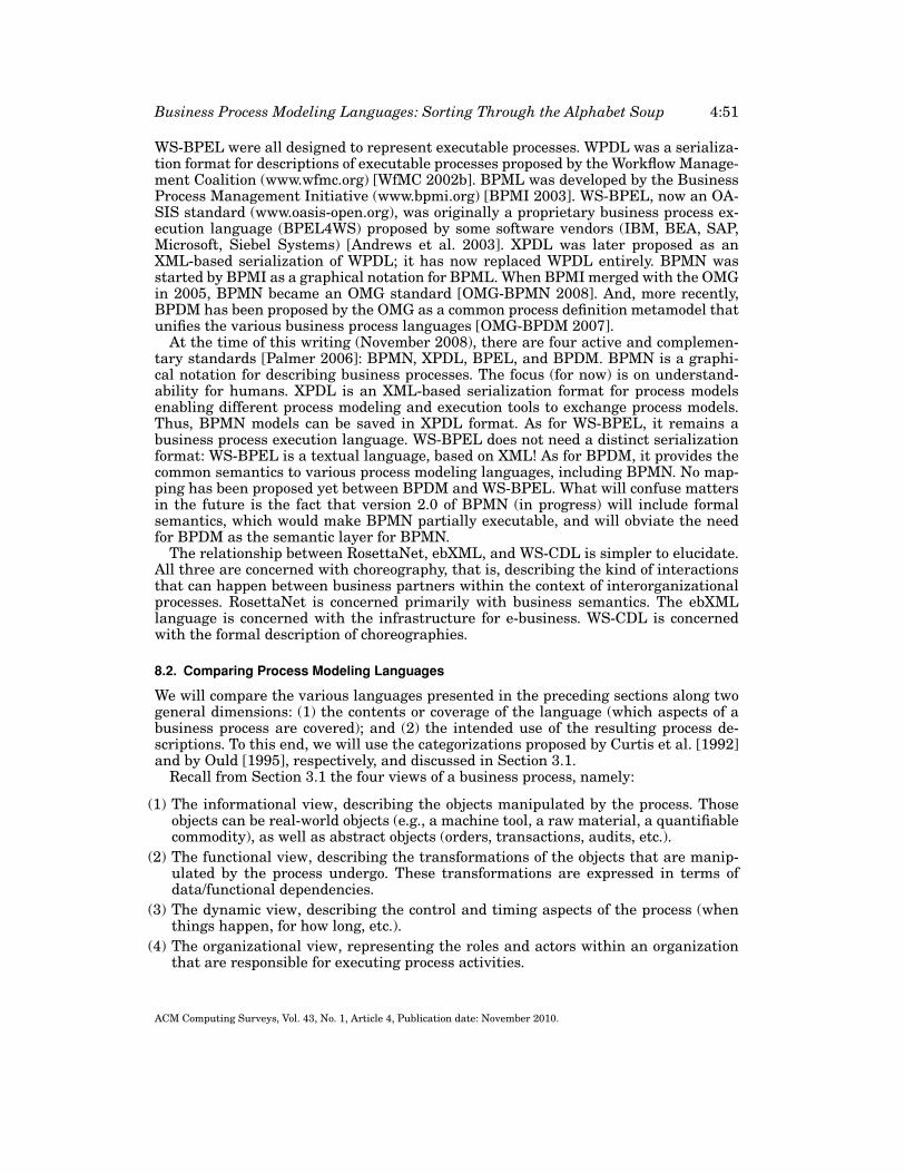
Business Process Modeling Languages: Sorting Through the Alphabet Soup 4:51
WS-BPEL were all designed to represent executable processes. WPDL was a serializa-tion format for descriptions of executable processes proposed by the Workflow Manage-ment Coalition (www.wfmc.org) [WfMC 2002b]. BPML was developed by the BusinessProcess Management Initiative (www.bpmi.org) [BPMI 2003]. WS-BPEL, now an OA-SIS standard (www.oasis-open.org), was originally a proprietary business process ex-ecution language (BPEL4WS) proposed by some software vendors (IBM, BEA, SAP,Microsoft, Siebel Systems) [Andrews et al. 2003]. XPDL was later proposed as anXML-based serialization of WPDL; it has now replaced WPDL entirely. BPMN wasstarted by BPMI as a graphical notation for BPML. When BPMI merged with the OMGin 2005, BPMN became an OMG standard [OMG-BPMN 2008]. And, more recently,BPDM has been proposed by the OMG as a common process definition metamodel thatunifies the various business process languages [OMG-BPDM 2007].
At the time of this writing (November 2008), there are four active and complemen-tary standards [Palmer 2006]: BPMN, XPDL, BPEL, and BPDM. BPMN is a graphi-cal notation for describing business processes. The focus (for now) is on understand-ability for humans. XPDL is an XML-based serialization format for process modelsenabling different process modeling and execution tools to exchange process models.Thus, BPMN models can be saved in XPDL format. As for WS-BPEL, it remains abusiness process execution language. WS-BPEL does not need a distinct serializationformat: WS-BPEL is a textual language, based on XML! As for BPDM, it provides thecommon semantics to various process modeling languages, including BPMN. No map-ping has been proposed yet between BPDM and WS-BPEL. What will confuse mattersin the future is the fact that version 2.0 of BPMN (in progress) will include formalsemantics, which would make BPMN partially executable, and will obviate the needfor BPDM as the semantic layer for BPMN.
The relationship between RosettaNet, ebXML, and WS-CDL is simpler to elucidate.All three are concerned with choreography, that is, describing the kind of interactionsthat can happen between business partners within the context of interorganizationalprocesses. RosettaNet is concerned primarily with business semantics. The ebXMLlanguage is concerned with the infrastructure for e-business. WS-CDL is concernedwith the formal description of choreographies.
8.2. Comparing Process Modeling Languages
We will compare the various languages presented in the preceding sections along twogeneral dimensions: (1) the contents or coverage of the language (which aspects of abusiness process are covered); and (2) the intended use of the resulting process de-scriptions. To this end, we will use the categorizations proposed by Curtis et al. [1992]and by Ould [1995], respectively, and discussed in Section 3.1.
Recall from Section 3.1 the four views of a business process, namely:
(1) The informational view, describing the objects manipulated by the process. Thoseobjects can be real-world objects (e.g., a machine tool, a raw material, a quantifiablecommodity), as well as abstract objects (orders, transactions, audits, etc.).
(2) The functional view, describing the transformations of the objects that are manip-ulated by the process undergo. These transformations are expressed in terms ofdata/functional dependencies.
(3) The dynamic view, describing the control and timing aspects of the process (whenthings happen, for how long, etc.).
(4) The organizational view, representing the roles and actors within an organizationthat are responsible for executing process activities.
ACM Computing Surveys, Vol. 43, No. 1, Article 4, Publication date: November 2010.
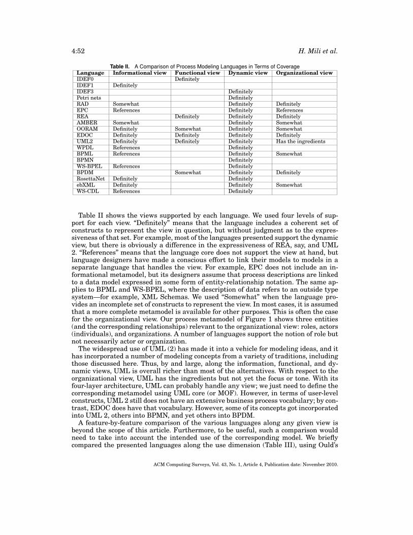
4:52 H. Mili et al.
Table II. A Comparison of Process Modeling Languages in Terms of CoverageLanguage Informational view Functional view Dynamic view Organizational viewIDEF0 DefinitelyIDEF1 DefinitelyIDEF3 DefinitelyPetri nets DefinitelyRAD Somewhat Definitely DefinitelyEPC References Definitely ReferencesREA Definitely Definitely DefinitelyAMBER Somewhat Definitely SomewhatOORAM Definitely Somewhat Definitely SomewhatEDOC Definitely Definitely Definitely DefinitelyUML2 Definitely Definitely Definitely Has the ingredientsWPDL References DefinitelyBPML References Definitely SomewhatBPMN DefinitelyWS-BPEL References DefinitelyBPDM Somewhat Definitely DefinitelyRosettaNet Definitely DefinitelyebXML Definitely Definitely SomewhatWS-CDL References Definitely
Table II shows the views supported by each language. We used four levels of sup-port for each view. “Definitely” means that the language includes a coherent set ofconstructs to represent the view in question, but without judgment as to the expres-siveness of that set. For example, most of the languages presented support the dynamicview, but there is obviously a difference in the expressiveness of REA, say, and UML2. “References” means that the language core does not support the view at hand, butlanguage designers have made a conscious effort to link their models to models in aseparate language that handles the view. For example, EPC does not include an in-formational metamodel, but its designers assume that process descriptions are linkedto a data model expressed in some form of entity-relationship notation. The same ap-plies to BPML and WS-BPEL, where the description of data refers to an outside typesystem—for example, XML Schemas. We used “Somewhat” when the language pro-vides an incomplete set of constructs to represent the view. In most cases, it is assumedthat a more complete metamodel is available for other purposes. This is often the casefor the organizational view. Our process metamodel of Figure 1 shows three entities(and the corresponding relationships) relevant to the organizational view: roles, actors(individuals), and organizations. A number of languages support the notion of role butnot necessarily actor or organization.
The widespread use of UML (2) has made it into a vehicle for modeling ideas, and ithas incorporated a number of modeling concepts from a variety of traditions, includingthose discussed here. Thus, by and large, along the information, functional, and dy-namic views, UML is overall richer than most of the alternatives. With respect to theorganizational view, UML has the ingredients but not yet the focus or tone. With itsfour-layer architecture, UML can probably handle any view; we just need to define thecorresponding metamodel using UML core (or MOF). However, in terms of user-levelconstructs, UML 2 still does not have an extensive business process vocabulary; by con-trast, EDOC does have that vocabulary. However, some of its concepts got incorporatedinto UML 2, others into BPMN, and yet others into BPDM.
A feature-by-feature comparison of the various languages along any given view isbeyond the scope of this article. Furthermore, to be useful, such a comparison wouldneed to take into account the intended use of the corresponding model. We brieflycompared the presented languages along the use dimension (Table III), using Ould’s
ACM Computing Surveys, Vol. 43, No. 1, Article 4, Publication date: November 2010.

Business Process Modeling Languages: Sorting Through the Alphabet Soup 4:53
Table III. Potential Uses of the Various LanguagesDescription Analysis Enactment
Language Human Machine Qualitative Quantitative Simulation ExecutionIDEF0 Yes YesIDEF1 Yes YesIDEF3 Yes YesPetri nets Somewhat Yes Somewhat Yes Yes SomewhatRAD Yes Yes Somewhat SomewhatEPC Yes Yes Yes PossiblyREA Yes Somewhat YesAMBER Somewhat Yes Yes YesOORAM Yes Yes YesEDOC Yes Yes Yes Possibly YesUML2 Yes Yes Yes Possibly YesWPDL Yes Yes YesBPML Yes YesBPMN Yes In the future Yes In the future PotentiallyWS-BPEL Yes Yes Yes YesBPDM Yes YesRosettaNet Yes Yes SomewhatebXML Yes Yes SomewhatWS-CDL Yes Yes Yes
classification [Ould 1995]. Recall from Section 3.1 the potential uses of a processmodel:
(1) description, to either a human being or to a machine,(2) analysis, both qualitative (for reengineering) and qualitative (for detecting dead-
locks, races, etc.); and(3) enactment, for both simulation and execution.
This matrix belies a few trends. First, as would be expected, languages for commu-nicating processes to humans do not support those tasks that require formality andprecision, namely, quantitative analyses and enactment. Second, the machine read-ability aspect refers more to the existence of a serialization format, rather than tothe level of formality. A number of languages have textual serialization formats thatsupport process description interchange. EDOC and UML 2 (and OORAM) use XMI,WS-BPEL, BPML, ebXML and XPDL use XML, and so forth. Further, while a few lan-guages have been noted to support quantitative analyses, the type of analyses that aresupported can vary widely. The value “possibly” refers to the fact that a given modelmay be transformed into a simplified model that supports some kinds of analyses. Forexample, researchers have often tried to extract Petri nets or finite state machinesfrom dynamic models to perform analyses. We cannot say that UML’s dynamic modelsupports deadlock detection, but if we extract and merge state machines from stat-echarts of various classes, we might get a state machine model that supports thingssuch as deadlock detection, reachability analysis, and the like.
REFERENCES
ANDREWS, T., CURBERA, F., DHOLAKIA, H., GOLAND, Y., KLEIN, J., LEYMANN, F., LIU, K., ROLLER, D., SMITH, D.,THATTE, S., TRICKOVIC, A., AND WEERAWARANA, S. 2003. Business process execution language for webservices, version 1.1. http://www.ibm.com/developerworks/library/ws-bpel/.
BARROS, A., DUMAS, M., AND OAKS, P. 2005. A critical overview of the web services choreography descriptionlanguage (WS-CDL). http://www.bptrends. com/publicationfiles/03–05 WP WS-CDL Barros et al.pdf.
BOLOGNESI, T. AND BRINKSMA, E. 1987. Introduction to the ISO specification language LOTOS. Comput.Netw. ISDN Syst.14, 25–59.
ACM Computing Surveys, Vol. 43, No. 1, Article 4, Publication date: November 2010.
4:54 H. Mili et al.
BOOCH, G., RUMBAUCH, J., AND JACOBSON, I. 1999. The Unified Modeling Language User Guide. Addison-Wesley, Reading, MA.
BPMI. 2003. Business Process Modeling Language. Business Process Management Institute.BROOKS, F. 1987. No silver bullet: Essence and accidents of software engineering. Computer 20, 4, 10–19.CARLSON, W. M. 1979. Business information analysis and integration technique (BIAIT)–The new horizon.
Data Base 10, 4, 3–9.CARBONE, M., HONDA, K., AND YOSHIDA, N. 2007. Structured communication-centered programming for
Web services. In Proceedings of the 16th European Symposium on Programming (ESOP). R. De NicolaEd., Lecture Notes in Computer Science, vol. 4421, Springer, Berlin, 2–17.
COAD, P. AND YOURDON, E. 1989. Object-Oriented Analysis. 1st Ed. Prentice-Hall, Englewood Cliffs, NJ.COLEMAN, D., ARNOLD, P., BODOFF, S., DOLLIN, C., AND GILCHRIST, H. 1994. Object-Oriented Development:
The Fusion Method. Prentice-Hall, Englewood Cliffs, NJ.CURTIS, B., KELLNER, M.I., AND OVER, J. 1992. Process modeling. Comm. ACM 35, 9, 75–90.DAYAL, U., HSU, M., AND LADIN, R. 2001. Business process coordination: State of the art, trends and open
issues. In Proceedings of the 27th International Conference on Very Large Data Bases (VLDB’01). 3–13.DIJKMAN, R. AND DUMAS, M. 2004. Service-oriented design: A multi-viewpoint approach. Int. J. Coop, In-
form. Syst. 13, 4, 337–378.DOGAC, A., TAMBAG, Y., PEMBECIOGLU, P., PEKTAS, S., LALECI, G., KURT, G., TOPRAK, S., AND KABAK, Y. 2002.
An ebXML infrastructure implementation through UDDI registries and RosettaNet PIPs. In Proceed-ings of the ACM SIGMOD Conference. ACM, New York, 512–523.
DUSSART, A., AUBERT, B., AND PATRY, M. 2002. An Evaluation of inter-organizational workflow modelingformalisms. Tech. rep. 2002 s-64, CIRANO. http://www.cirano. qc. ca.
ebXML. 2001a. ebXML Business process specification schema version 1.01.www.ebxml.org/specs/ebBPSS.pdf.
ebXML. 2001b. Collaboration-protocol profile and agreement specification version 1.0.www.ebxml.org/specs/ebCCP.pdf.
ebXML. 2001c. ebXML registry service specification version 1.0. http://www.ebxml.org/specs/ebRS.pdf.EERTINK, H., JANSSEN, W., LUTTIGHUIS, P. A., TEEUW, W., AND VISSERS, C. 1999. A business process design
language. In Proceedings of the World Congress on Formal Methods in the Development of ComputingSystems (FM’99). Lecture Notes in Computer Science, vol. 1119, Springer, Berlin, 76–95.
ERIKSSON, H-E. AND PENKER, M. 2000. Business Modeling with UML: Business Patterns at Work. OMGPress, Wiley.
FERNANDEZ, J.-C., GARAVEL, H., KERBRAT, A., MOUNIER, L., MATEESCU, R., AND SIGHIREANU, M. 1996. CADP:A protocol validation and verification toolbox. In Computer-Aided Verification, Lecture Notes in Com-puter Science, vol. 1102, Springer, Berlin, 437–440.
FIPS. 1993. Integration definition for information modeling (IDEF1X). Federal Information ProcessingStandards, publication 184.
GALE, T. AND ELDRED, J. 1996. Getting Results with the Object-Oriented Enterprise Model. SIGS Books.GEERTS, G. L. AND MCCARTHY, W. E. 1997. Modeling business enterprises as value-added process hier-
archies with resource-event-agent object templates. In Business Object Design and Implementation, J.Sutherland and D. Patel Eds., Springer, Berlin, 94–113.
GLYKAS, M. AND VALIRIS, G. 1999. Formal methods in object-oriented business modeling. J. Syst. Softw. 48,27–41.
GRUHN, V. AND WELLEN, U. 2001. Analyzing a process landscape by simulation. J. Syst. Softw. 59,333–342.
HAMMER, M. 1990. Reengineering work: Don’t automate, obliterate. Harvard Bus. Rev. (July-Aug.), 104–112.
HAMMER, M. AND CHAMPY, J. 1993. Reengineering the Corporation. Harper Business, New York.HAUGHEN, R. AND MCCARTHY, W. E. 2000. REA, a semantic model for Internet supply chain collabora-
tion. In Proceedings of the OOPSLA Workshop on Business Object Components: Enterprise ApplicationIntegration.
HENDERSON-SELLERS, B. AND EDWARDS, J. M. 1990. The object-oriented systems life cycle. Comm. ACM 33,9, 143–159.
HOLLINGSWORTH, D. 1995. The workflow reference model. Doc. TC00–1003, Workflow Management Coali-tion.
IJIRI, Y. 1975. The Theory of Accounting Measurement. American Accounting Association, Sarasota, FL.ISODA, S. 2001. Object-oriented real-world modeling revisited. J. Syst. Softw. 59, 153–162.
ACM Computing Surveys, Vol. 43, No. 1, Article 4, Publication date: November 2010.
Business Process Modeling Languages: Sorting Through the Alphabet Soup 4:55
JACKSON, M. AND TWADDLE, D. 1997. Business Process Implementation: Building Workflow Systems. Addi-son Wesley, Reading, MA.
JACOBSON, I., CHRISTERSON, M., JONSSON, P., AND OVERGAARD, G. 1992. Object-Oriented SoftwareEngineering—A Use Case Driven Approach. Addison-Wesley, Reading, MA.
JANSSEN, W., MATEESCU, R., MAUW, S., AND SPRINGINTVELD, J. 1998. Verifying business processes usingSPIN. In Proceedings of the 4th International SPIN Workshop. G. Holzman et al. Eds., 21–36.
KAVANTAS, N., BURDETT, D., RITZINGER, G., FLETCHER, T., LAFON, Y., AND BARRETO, C. 2005. Web serviceschoreography description language, version 1.0. http://www. w3.org/TR/ws-cdl-10.
KELLER, G., NUTTGENS, M., AND SCHEER, A. W. 1992. Semantische Prozessmodellierung auf derGrundlage Ereignisgesteuerter Prozessketten (EPK). Institut fur Wirtschaftsinformatik. Paper 89,Saarbrucken.
KINDLER, E. 2003. On the semantics of EPCs: A framework for resolving the vicious circle. Tech. rep.,Reihe Informatik, University of Paderborn.
LEE, J., GRUNINGER, M., JIN, Y., MALONE, T., TATE, A., YOST, G., AND OTHER MEMBERS OF THE PIF WORKING
GROUP 1996. The PIF Process Interchange Format and Framework. http://ccs. mit.edu/pif8.html.MCCARTHY, W.E. 1980. Construction and use of integrated accounting systems with entity-relationship
modeling. In Entity-Relationship Approach to Systems Analysis and Design, P. Chen Eds., North Hol-land, Amsterdam, 625–637.
MCCARTHY, W. E. 1982. The REA Accounting model: A generalized framework for accounting systems ina shared data environment. The Accounting Rev. (July), 554–578.
MALONE, T. W., CROWSTON, K., LEE, J., PENTLAND, B., DELLAROCAS, C., WYNER, G., QUIMBY, J., OSBORN, C. S.,BERNSTEIN, A., HERMAN, G., KLEIN, M., AND O’DONNELL, E. 1999. Tools for inventing organizations:Toward a handbook of organizational processes. Manage. Sci. 45, 3, 425–443.
MAYER, R. J., MENZEL, C.P., PAINTER, M. K., DEWITTE, P. S., BLINN, T., AND PARAKATH, B. 1995. Informa-tion integration for concurrent engineering (IICE) IDEF3 process description capture method report.Knowledge Based Systems Inc.
MILNER, R. 1999. Communicating and Mobile Systems: The π -Calculus. Cambridge University Press.MURATA, T. 1989. Petri nets: Properties, analysis and applications. Proc. IEEE 77, 4, 541–580.NIST. 2002. The process specification language (PSL 2.0). http://ats.nist.gov/psl/.OASIS. 2001. Business process and business information analysis overview. version 1.0 (ebXML).
http://www.ebxml.org/specs/bpOVER.pdf.OMG-EDOC. 2001. OMG, EDOC: UML profile for enterprise distributed object computing. Document
ptc/2001–12-04.OMG-BPDM. 2007. Business process definition metamodel. OMG document bmi/2007-03-01.OMG-BPMN. 2008. Business process modeling notation, V1.1. OMG document formal/2008-01-17.OMG-MDA. 2003. MDA guide version 1.0.1. J. Miller et al.. (eds.), OMG document omg/2003-06-01.OMG-UML-SUP. 2005. Unified modeling language: Superstructure. OMG document formal/05-07-04.OULD, M. A. AND ROBERTS, C. 1987. Defining formal models of the software development process. In Soft-
ware Engineering Environments, P. Brereton and E. Horwood Eds.OULD, M. A. 1995. Business Processes: Modelling and Analysis for Reengineering and Improvement. Wiley,
New York.PALMER, N. 2006. Understanding the BPMN-XPDL-BPEL value chain. Bus. Integration J. (Nov./Dec.),
54–55.PETERSON, J. L. 1981. Petri Nets Theory and the Modeling of Systems. Prentice-Hall, Englewood Cliffs, NJ.PHALP, K. 1998. The CAP framework for business process modeling. Inform. Softw. Technol. 40, 731–744.PHALP, K. AND SHEPPERD, M. 2000. Quantitative analysis of static models of processes. J. Syst. Softw. 52,
105–112.PELTZ, C. 2003. Web services orchestration and choreography. IEEE Computer 36, 10, 46–52.REENSKAUG, T. 1996. Working with Objects: The OORAM Software Engineering Methodology. Manning.ROSETTANET. 2003. http://www.rosettanet.org.ROSS, D. T. AND SCHOMAN, K.E. 1977. Structured analysis for requirements definition. IEEE Trans. Softw.
Eng. 3, 1, 6–15.RUMBAUGH, J., BLAHA, M., PREMERLANI, W., EDDY, F., AND LORENSEN, W. 1991. Object-Oriented Modeling
and Design. Prentice-Hall, Englewood Cliffs, NJ.RUMBAUGH, J., JACOBSON, I., AND BOOCH, G. The Unified Modeling Language Reference Manual. Addison-
Wesley, Reading, MA.
ACM Computing Surveys, Vol. 43, No. 1, Article 4, Publication date: November 2010.
4:56 H. Mili et al.
SHLAER, S. AND MELLOR, S. J. 1992. Object Lifecycles—Modeling the World in States. Yourdon Press Com-puting Series.
TURBAN, E., LEE, J., KING, D., AND CHUNG, H. M. 1999. Electronic Commerce: A Managerial Perspective.Prentice-Hall, Englewood Clidfs, NJ.
V. D. AALST, W. M. P. 1999. Formalization and verification of event-driven process chains. Inform. Softw.Technol. 41,10, 639–650.
WfMC. 1995. Workflow management coalition. The Workflow Reference Model, document TC00–1003.http://www.wfmc.org.
WfMC. 1998. Workflow management coalition. The Workflow Management Application Programming In-terface Specification, WfMC-TC-1009 – V 2.0.
WfMC. 1999a. Workflow management coalition. Interface 1: Process definition interchange processmodel. WfMC-TC-1016-P, version 1.1.
WfMC. 1999b. Workflow management coalition. Terminology and glossary, document WfMC-TC-1011.WfMC. 2002a. An introduction to workflow. In The Workflow Handbook, L. Fischer (Ed.), Workflow Man-
agement Coalition.WfMC. 2002b. Workflow management coalition. Workflow process definition interface–XML process defi-
nition language, WfMC-TC-1025.YOURDON, E. N. 1989. Modern Structured Analysis. Prentice-Hall, Englewood Cliffs, NJ.YU, S. C. 1976. The Structure of Accounting Theory. The University Presses of Florida.
Received March 2007; accepted March 2009
ACM Computing Surveys, Vol. 43, No. 1, Article 4, Publication date: November 2010.