Embed Size (px)
Citation preview
Optimal Design of a Golf Club using Functionally Graded Porosity
Phillip Ray*, Gilbert Chahine*, Pauline Smith**, and R. Kovacevic*,
*Research Center for Advanced Manufacturing, Southern Methodist University Dallas, Texas 75206 **The Army Research Laboratory, Aberdeen Proving Ground, MD 21005
Abstract
The current work portrays a new concept of designing and manufacturing golf club heads with functionally graded porosity (FGP) by means of electron beam melting® (EBM®). In light of the advancement of additive manufacturing (AM) technologies and the consequent wide spread applications in the aerospace, automotive, and biomedical industries, the current work discusses a new application in sport technologies; for example, in the golf industry. EBM® makes it possible to print the designed porosity within a golf club head, to reduce the weight and optimize performance. The focus is to design the golf club head with FGP to improve performance and reduce weight. The dynamic properties of porous materials are investigated theoretically. The porosity in the club head was analyzed numerically by simulating the impact between the club head and a steel ball in order to determine the coefficient of restitution (COR) of the club head. The simulation’s parameters are in compliance with the U.S Golf Association’s (USGA) test procedure for measuring COR.
Keywords: golf club head, electron beam melting (EBM), additive manufacturing (AM), functionally graded porosity (FGP)
Introduction
Porous materials have been an area of research for the last 20 years due to their unique mechanical properties and light weight. Metal foams can be designed to specific performance criteria, by controlling the parameters of the foaming process used for manufacturing. However, the foaming process is stochastic in nature and cannot control the porosity of the melted foam. New additive manufacturing (AM) technology makes the production of periodic porous structures that have user defined mechanical properties possible (Figure 1). The mechanical properties of controlled structures have been investigated by Ashby et al., and they have found that the properties compare favorably with those of metallic foams [1]. The capabilities of AM technologies allow for precise variances of porosity throughout a part, which further widens the possibilities for user defined design. Functionally graded porosity (FGP) is the local tailoring of porosity to be compliant with user defined mechanical or thermal performance [2]. The aim of this paper is to investigate the dynamic properties of porous structures for use in golf club heads.
657
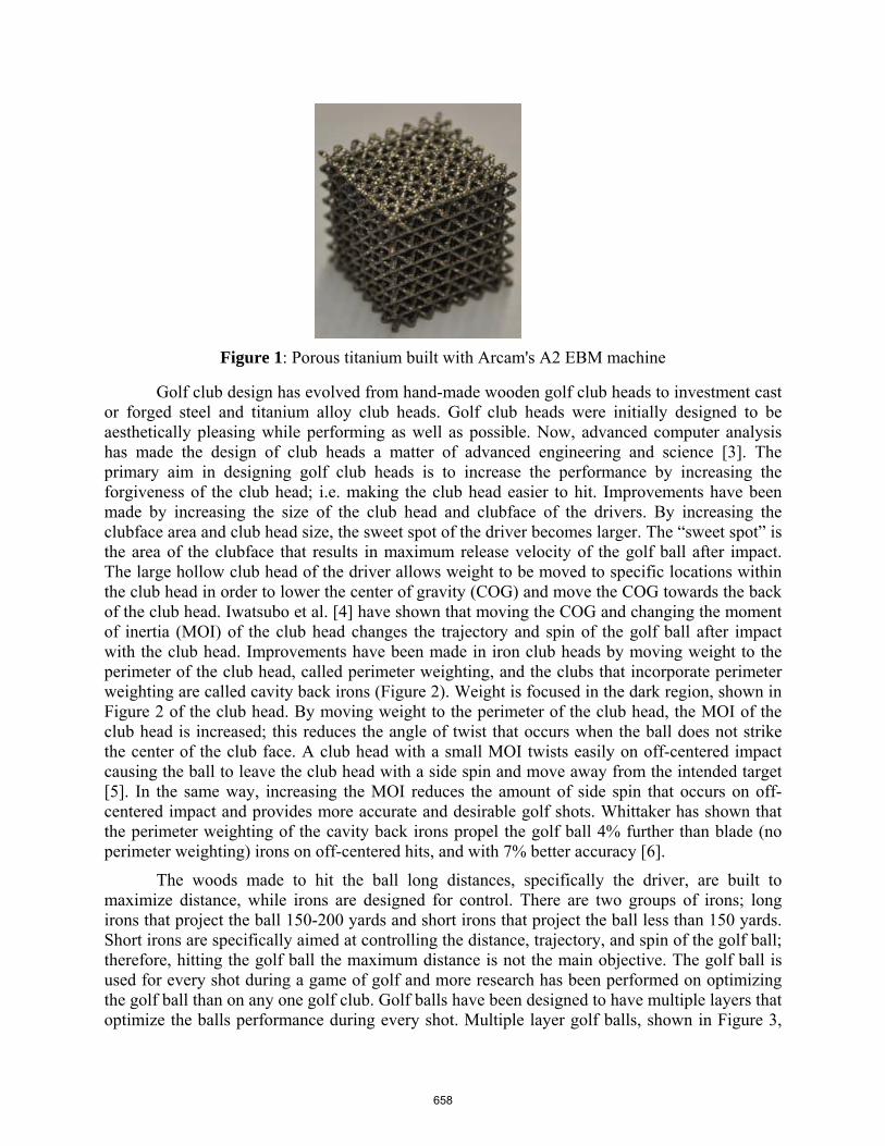
Figure 1: Porous titanium built with Arcam's A2 EBM machine
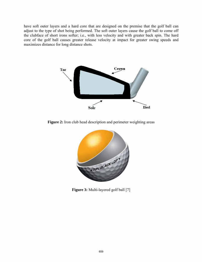
Golf club design has evolved from hand-made wooden golf club heads to investment cast or forged steel and titanium alloy club heads. Golf club heads were initially designed to be aesthetically pleasing while performing as well as possible. Now, advanced computer analysis has made the design of club heads a matter of advanced engineering and science [3]. The primary aim in designing golf club heads is to increase the performance by increasing the forgiveness of the club head; i.e. making the club head easier to hit. Improvements have been made by increasing the size of the club head and clubface of the drivers. By increasing the clubface area and club head size, the sweet spot of the driver becomes larger. The “sweet spot” is the area of the clubface that results in maximum release velocity of the golf ball after impact. The large hollow club head of the driver allows weight to be moved to specific locations within the club head in order to lower the center of gravity (COG) and move the COG towards the back of the club head. Iwatsubo et al. [4] have shown that moving the COG and changing the moment of inertia (MOI) of the club head changes the trajectory and spin of the golf ball after impact with the club head. Improvements have been made in iron club heads by moving weight to the perimeter of the club head, called perimeter weighting, and the clubs that incorporate perimeter weighting are called cavity back irons (Figure 2). Weight is focused in the dark region, shown in Figure 2 of the club head. By moving weight to the perimeter of the club head, the MOI of the club head is increased; this reduces the angle of twist that occurs when the ball does not strike the center of the club face. A club head with a small MOI twists easily on off-centered impact causing the ball to leave the club head with a side spin and move away from the intended target [5]. In the same way, increasing the MOI reduces the amount of side spin that occurs on off-centered impact and provides more accurate and desirable golf shots. Whittaker has shown that the perimeter weighting of the cavity back irons propel the golf ball 4% further than blade (no perimeter weighting) irons on off-centered hits, and with 7% better accuracy [6].
The woods made to hit the ball long distances, specifically the driver, are built to maximize distance, while irons are designed for control. There are two groups of irons; long irons that project the ball 150-200 yards and short irons that project the ball less than 150 yards. Short irons are specifically aimed at controlling the distance, trajectory, and spin of the golf ball; therefore, hitting the golf ball the maximum distance is not the main objective. The golf ball is used for every shot during a game of golf and more research has been performed on optimizing the golf ball than on any one golf club. Golf balls have been designed to have multiple layers that optimize the balls performance during every shot. Multiple layer golf balls, shown in Figure 3,
658
have soft outer layers and a hard core that are designed on the premise that the golf ball can adjust to the type of shot being performed. The soft outer layers cause the golf ball to come off the clubface of short irons softer; i.e., with less velocity and with greater back spin. The hard core of the golf ball causes greater release velocity at impact for greater swing speeds and maximizes distance for long distance shots.
Figure 2: Iron club head description and perimeter weighting areas
Figure 3: Multi-layered golf ball [7]
659
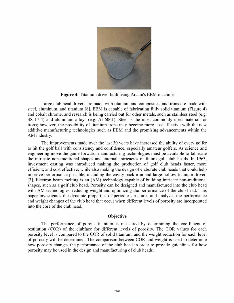
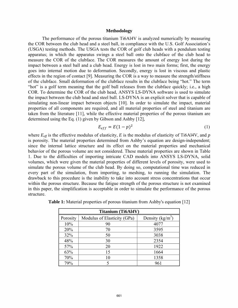
Figure 4: Titanium driver built using Arcam's EBM machine
Large club head drivers are made with titanium and composites, and irons are made with steel, aluminum, and titanium [8]. EBM is capable of fabricating fully solid titanium (Figure 4) and cobalt chrome, and research is being carried out for other metals, such as stainless steel (e.g. SS 17-4) and aluminum alloys (e.g. Al 6061). Steel is the most commonly used material for irons; however, the possibility of titanium irons may become more cost effective with the new additive manufacturing technologies such as EBM and the promising advancements within the AM industry.
The improvements made over the last 30 years have increased the ability of every golfer to hit the golf ball with consistency and confidence, especially amateur golfers. As science and engineering move the game forward, manufacturing technologies must be available to fabricate the intricate non-traditional shapes and internal intricacies of future golf club heads. In 1963, investment casting was introduced making the production of golf club heads faster, more efficient, and cost effective, while also making the design of elaborate club heads that could help improve performance possible, including the cavity back iron and large hollow titanium driver. [3]. Electron beam melting is an (AM) technology capable of building intricate non-traditional shapes, such as a golf club head. Porosity can be designed and manufactured into the club head with AM technologies, reducing weight and optimizing the performance of the club head. This paper investigates the dynamic properties of periodic structures and analyzes the performance and weight changes of the club head that occur when different levels of porosity are incorporated into the core of the club head.
Objective
The performance of porous titanium is measured by determining the coefficient of restitution (COR) of the clubface for different levels of porosity. The COR values for each porosity level is compared to the COR of solid titanium, and the weight reduction for each level of porosity will be determined. The comparison between COR and weight is used to determine how porosity changes the performance of the club head in order to provide guidelines for how porosity may be used in the design and manufacturing of club heads.
660
Methodology
The performance of the porous titanium Ti6Al4V is analyzed numerically by measuring the COR between the club head and a steel ball, in compliance with the U.S. Golf Association’s (USGA) testing methods. The USGA tests the COR of golf club heads with a pendulum testing apparatus; in which the apparatus swings a steel ball onto the clubface of the club head to measure the COR of the clubface. The COR measures the amount of energy lost during the impact between a steel ball and a club head. Energy is lost in two main forms; first, the energy goes into internal motion due to deformation. Secondly, energy is lost in viscous and plastic effects in the region of contact [9]. Measuring the COR is a way to measure the strength/stiffness of the clubface. Small deformation of the clubface results in the clubface being “hot.” The term “hot” is a golf term meaning that the golf ball releases from the clubface quickly; i.e., a high COR. To determine the COR of the club head, ANSYS LS-DYNA software is used to simulate the impact between the club head and steel ball. LS-DYNA is an explicit solver that is capable of simulating non-linear impact between objects [10]. In order to simulate the impact, material properties of all components are required, and all material properties of steel and titanium are taken from the literature [11], while the effective material properties of the porous titanium are determined using the Eq. (1) given by Gibson and Ashby [12],
1 (1)
where Eeff is the effective modulus of elasticity, E is the modulus of elasticity of Ti6Al4V, and p is porosity. The material properties determined from Ashby’s equation are design-independent; since the internal lattice structure and its effect on the material properties and mechanical behavior of the porous volume are not considered. These material properties are shown in Table 1. Due to the difficulties of importing intricate CAD models into ANSYS LS-DYNA, solid volumes, which were given the material properties of different levels of porosity, were used to simulate the porous volume of the club head. By doing so, computational time was reduced in every part of the simulation, from importing, to meshing, to running the simulation. The drawback to this procedure is the inability to take into account stress concentrations that occur within the porous structure. Because the fatigue strength of the porous structure is not examined in this paper, the simplification is acceptable in order to simulate the performance of the porous structure.
Table 1: Material properties of porous titanium from Ashby's equation [12]
Titanium (Ti6Al4V)
Porosity Modulus of Elasticity (GPa) Density (kg/m3) 10% 90 4077 20% 70 3595 32% 50 3038 48% 30 2354 57% 20 1922 63% 15 1664 70% 10 1358 79% 5 961
661
ANSYS LS-DYNA is capable of computing values for numerical analysis, such as nodal velocity, displacement, and stress. In order to obtain the COR of the simulation, the average velocity of the ball must be computed. To determine the COR, the definition of the COR is necessary because the type of collision changes the equation for the COR. To determine the COR, Eq. (2) is used, [13].
(2)
This is the simplest form of determining the COR because it does not take into account the mass of the impacting components, i.e., the ball and club head. The simulation is done in compliance with the USGA method of testing the COR by having a steel ball impact the clubface of the club head. The impact problem for this analysis is a ball with an initial velocity colliding with a stationary club head. This simulation allows for the use of Eq. (2) to determine the COR. The numerical setup focuses on the reaction of the club head without taking into consideration the change in angle of the club head, which is present at impact of the golf ball with the golf club head. This impact is important because the performance of the materials within the club head is of interest to this paper.
In order to get consistent and accurate results that emphasize the mechanical performance of the porous volume, the setup of the LS-DYNA simulation is critical. A dynamic analysis in LS-DYNA consists of five primary steps that determine how the components of the simulation interact during the moment of impact. The steps below show how the parameters of the simulation are implemented.
1. Material properties: The material properties of different levels of porosity are determined from Gibson and Ashby’s equation and are given in Table 1. The modulus of elasticity and density are given to define the material within ANSYS LS-DYNA software to simulate the porous titanium.
a) b)
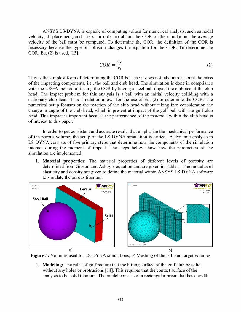
Figure 5: Volumes used for LS-DYNA simulations, b) Meshing of the ball and target volumes
2. Modeling: The rules of golf require that the hitting surface of the golf club be solid without any holes or protrusions [14]. This requires that the contact surface of the analysis to be solid titanium. The model consists of a rectangular prism that has a width
662
of 70 mm, a height of 40 mm, and a depth of 10 mm (Figure 4a). The size of the rectangular prism is chosen to resemble the porous volume area that would be embedded into the club head. The rectangular prism is glued to another rectangular prism with a width of 70 mm, a height of 40 mm, and depth of 1 mm of solid titanium in order to meet the USGA impact area requirements. The simplified rectangular prism is used to reduce the meshing time and meshing accuracy helps ensure the accuracy of the simulation by allowing for mapped hexahedron elements to be used rather than free tetrahedron elements. The steel ball is modeled with the dimensions of the golf ball, which is 42.8 mm in diameter.
3. Meshing: Mapped hexahedron elements 1 mm in size are used in order to get the most accurate results possible while minimizing the computational expense. The steel ball is meshed using free tetrahedron elements of 4 mm in size (Figure 5b). The element size of both the rectangular prism and steel ball are determined by trial and error on preliminary simulations that result in the most accurate results based on already known COR values. The mesh size is determined to increase computational speed, while generating results with no mesh dependence.
4. Components: LS-DYNA requires the defining of components in which to apply contact type and initial conditions. The components of the simulations are the steel ball, the outer surface of the steel ball, and the surface of the 1-mm thick solid titanium rectangular prism. The components are defined by selecting the nodes of the specific areas or volumes specifying them as a certain component. The outer surface of the steel ball is defined as the contact component, the surface area of the 1-mm thick solid titanium rectangular prism is defined as the target component, and the surface area of the steel ball is defined to apply initial velocity to the steel ball.
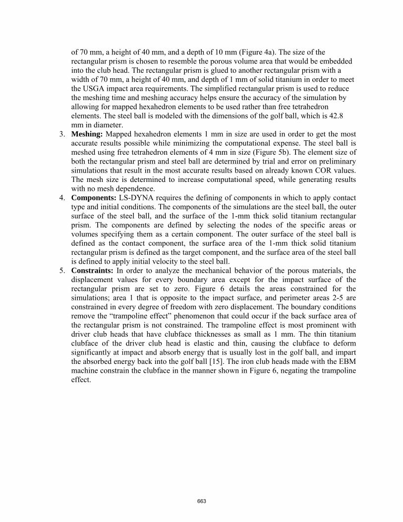
5. Constraints: In order to analyze the mechanical behavior of the porous materials, the displacement values for every boundary area except for the impact surface of the rectangular prism are set to zero. Figure 6 details the areas constrained for the simulations; area 1 that is opposite to the impact surface, and perimeter areas 2-5 are constrained in every degree of freedom with zero displacement. The boundary conditions remove the “trampoline effect” phenomenon that could occur if the back surface area of the rectangular prism is not constrained. The trampoline effect is most prominent with driver club heads that have clubface thicknesses as small as 1 mm. The thin titanium clubface of the driver club head is elastic and thin, causing the clubface to deform significantly at impact and absorb energy that is usually lost in the golf ball, and impart the absorbed energy back into the golf ball [15]. The iron club heads made with the EBM machine constrain the clubface in the manner shown in Figure 6, negating the trampoline effect.
663
Figure 6: Boundary areas with zero displacement constraints
6. Defining contact type and initial conditions: The contact type used for these simulations is node to surface contact that requires a target and contact be defined. The target is the surface of the 1 mm thick solid titanium rectangular prism, while the contact is the surface of the steel ball. The initial condition of this simulation is the velocity of the steel ball. The velocity of the steel ball is defined by selecting every node attached to the steel ball and defining the initial velocity of those nodes to be 10 m/s.
7. Governing Equations: LS-DYNA is an explicit finite element solver that is capable of solving short-time, large deformation problems. ANSYS LS-DYNA solves the transient dynamic behavior of objects in contact by determining the solution to the Eq. (3), the conservation of momentum; Eq. (4), conservation of mass, and Eq. (5), conservation of energy equation [16].
Conservation of momentum equation:
, (3)
where the Cauchy stress, ρ is the current density, f is the body force density, and is acceleration.
Conservation of mass equation:
(4)
where V is the relative volume and ρ0 is the reference density.
Conservation of energy equation:
(5)
where sif is deviatoric stresses and p is deviatoric pressure.
664
More in depth explanation of the internal solving methods of LS-DYNA can be found in the LS-DYNA Theory Manual [16] and ANSYS LS-DYNA User’s Guide.
Results
The numerical results from the LS DYNA simulations of the impact of a steel ball and porous material show that there are multiple advantages of incorporating porosity in the club head. The relationship between porosity and the COR is advantageous in almost every way possible when the objective of short irons are considered. These golf clubs are used to hit the golf ball with back spin and with a high trajectory in order get the golf ball as close to the hole as possible. The relationship between the reduction of weight and the COR is advantageous when high levels of porosity are used in the club head. High levels of porosity result in the lowest values of COR and enable the most weight to be available for lowering the COG and maximizing the MOI. The reduced COR increases the “softness” of the club head, meaning that the golf ball comes off the clubface softer, with slower velocity.
The reduction of weight possible with porosity is shown in Eq. (6). The range of weight reduction is given in percentages to better understand the significance of the weight in the club head. The percentage of weight reduction is the amount of weight that is reduced from a completely solid club head. Cavity back irons reduce the weight of the club head by 36%, allowing for that weight to be redistributed to exterior areas to enhance performance. In Eq. (6) the cavity back design is defined as porosity equal to 100%, giving a weight percentage reduction of 36%. Cavity back irons have a thin clubface that is solid and results in a high COR.
% 0.361 (6)
The combination of reduced weight and high COR is optimal for long irons that are used to hit the golf ball far and with control. Conversely, the combination of weight reduction and reduced COR are optimal for short irons designed to control distance, increase back spin, and launch the golf ball with high trajectories. The MOI of cavity back and blade type are given in Whittaker’s paper on how mass distribution affects the performance of the golf club. The cavity back club head increases the MOI by 17% [6]. Whittaker numerically simulated how this increase in MOI improved accuracy by 7% and increased distance by 4% for off-center shots [6]. By incorporating porosity into the club head, the MOI can be adjusted to make the club head more forgiving.
The COG can also be adjusted with the weight reduced from the porous area of the club head. The COG of the club head changes the trajectory of the golf ball after impact. The closer the COG is to the sole of the club head, the higher the trajectory and greater the amount of back spin the golf ball experiences after impact. Traditional manufacturing technologies are only capable of manufacturing a solid club head; thus, the thick solid club head has the lowest COR. Porosity reduces the COR and the weight lost in the porous region of the club head allows for weight to be moved to the sole of the club head, lowering the COG for specialty clubs and further improving performance. The porosity incorporated in the club head will allows one-third of the club head weight to be moved to the perimeter of specialty clubs, which increases forgiveness, trajectory, and backspin.
665
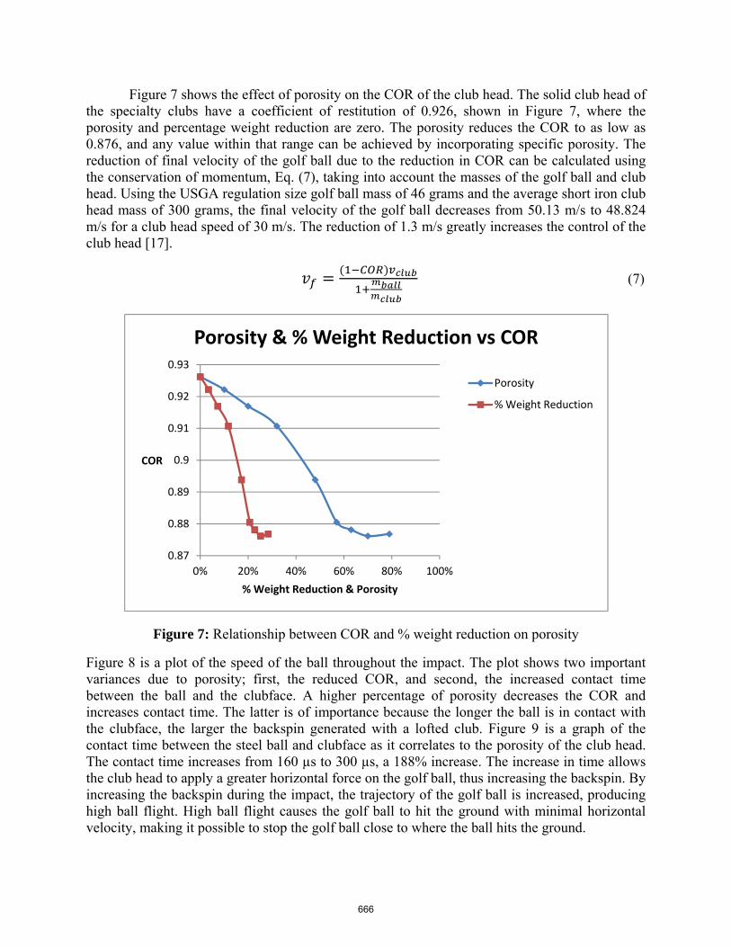
Figure 7 shows the effect of porosity on the COR of the club head. The solid club head of the specialty clubs have a coefficient of restitution of 0.926, shown in Figure 7, where the porosity and percentage weight reduction are zero. The porosity reduces the COR to as low as 0.876, and any value within that range can be achieved by incorporating specific porosity. The reduction of final velocity of the golf ball due to the reduction in COR can be calculated using the conservation of momentum, Eq. (7), taking into account the masses of the golf ball and club head. Using the USGA regulation size golf ball mass of 46 grams and the average short iron club head mass of 300 grams, the final velocity of the golf ball decreases from 50.13 m/s to 48.824 m/s for a club head speed of 30 m/s. The reduction of 1.3 m/s greatly increases the control of the club head [17].
(7)
Figure 7: Relationship between COR and % weight reduction on porosity
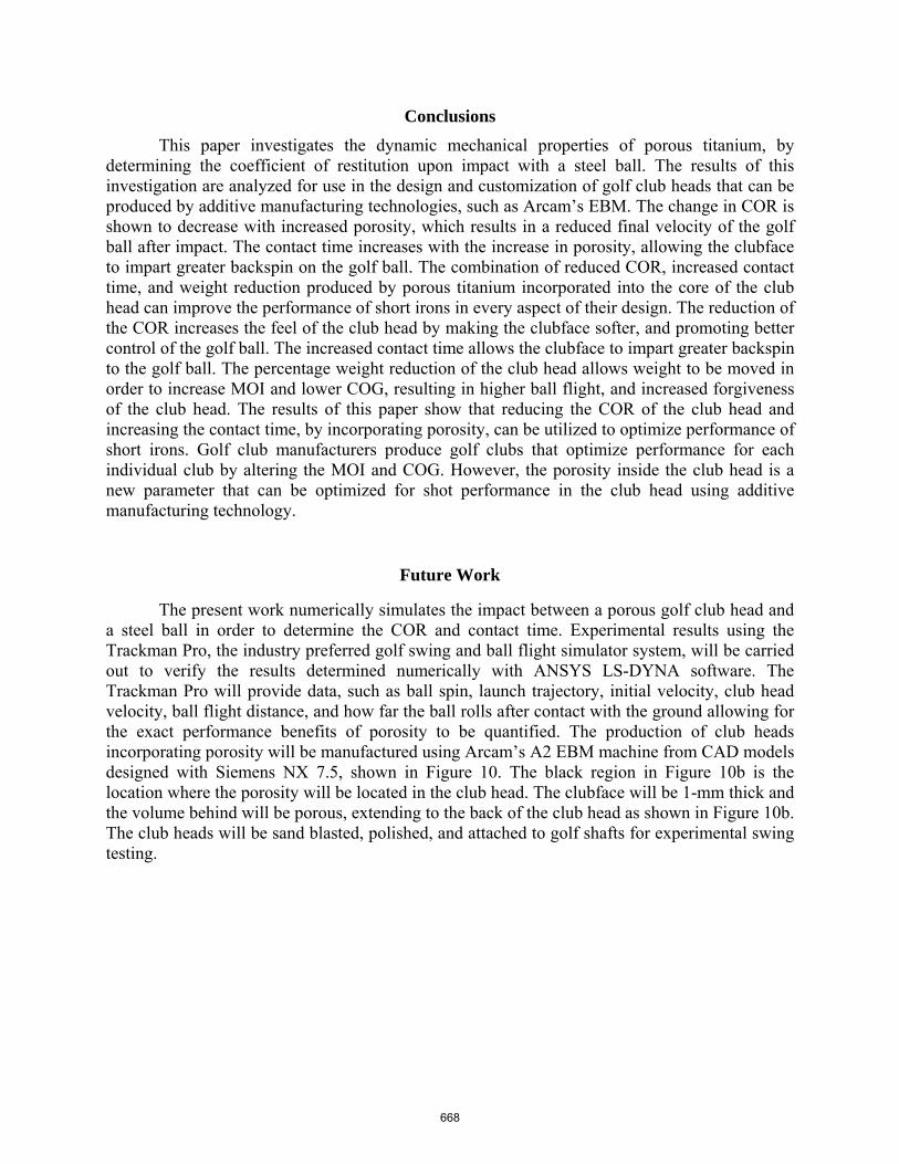
Figure 8 is a plot of the speed of the ball throughout the impact. The plot shows two important variances due to porosity; first, the reduced COR, and second, the increased contact time between the ball and the clubface. A higher percentage of porosity decreases the COR and increases contact time. The latter is of importance because the longer the ball is in contact with the clubface, the larger the backspin generated with a lofted club. Figure 9 is a graph of the contact time between the steel ball and clubface as it correlates to the porosity of the club head. The contact time increases from 160 µs to 300 µs, a 188% increase. The increase in time allows the club head to apply a greater horizontal force on the golf ball, thus increasing the backspin. By increasing the backspin during the impact, the trajectory of the golf ball is increased, producing high ball flight. High ball flight causes the golf ball to hit the ground with minimal horizontal velocity, making it possible to stop the golf ball close to where the ball hits the ground.
0.87
0.88
0.89
0.9
0.91
0.92
0.93
0% 20% 40% 60% 80% 100%
COR
% Weight Reduction & Porosity
Porosity & % Weight Reduction vs COR
Porosity
% Weight Reduction
666
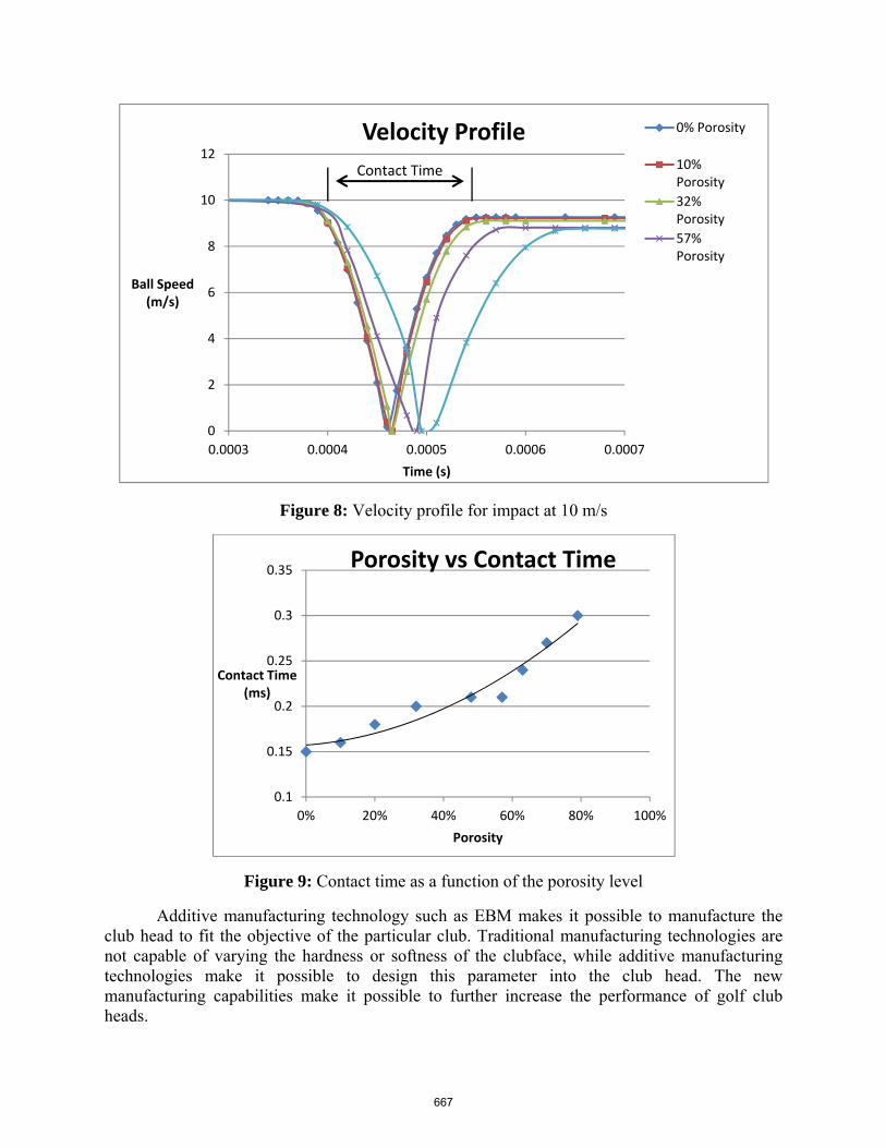
Figure 8: Velocity profile for impact at 10 m/s
Figure 9: Contact time as a function of the porosity level
Additive manufacturing technology such as EBM makes it possible to manufacture the club head to fit the objective of the particular club. Traditional manufacturing technologies are not capable of varying the hardness or softness of the clubface, while additive manufacturing technologies make it possible to design this parameter into the club head. The new manufacturing capabilities make it possible to further increase the performance of golf club heads.
0
2
4
6
8
10
12
0.0003 0.0004 0.0005 0.0006 0.0007
Ball Speed(m/s)
Time (s)
Velocity Profile 0% Porosity
10% Porosity
32% Porosity
57% Porosity
Contact Time
0.1
0.15
0.2
0.25
0.3
0.35
0% 20% 40% 60% 80% 100%
Contact Time(ms)
Porosity
Porosity vs Contact Time
667
Conclusions
This paper investigates the dynamic mechanical properties of porous titanium, by determining the coefficient of restitution upon impact with a steel ball. The results of this investigation are analyzed for use in the design and customization of golf club heads that can be produced by additive manufacturing technologies, such as Arcam’s EBM. The change in COR is shown to decrease with increased porosity, which results in a reduced final velocity of the golf ball after impact. The contact time increases with the increase in porosity, allowing the clubface to impart greater backspin on the golf ball. The combination of reduced COR, increased contact time, and weight reduction produced by porous titanium incorporated into the core of the club head can improve the performance of short irons in every aspect of their design. The reduction of the COR increases the feel of the club head by making the clubface softer, and promoting better control of the golf ball. The increased contact time allows the clubface to impart greater backspin to the golf ball. The percentage weight reduction of the club head allows weight to be moved in order to increase MOI and lower COG, resulting in higher ball flight, and increased forgiveness of the club head. The results of this paper show that reducing the COR of the club head and increasing the contact time, by incorporating porosity, can be utilized to optimize performance of short irons. Golf club manufacturers produce golf clubs that optimize performance for each individual club by altering the MOI and COG. However, the porosity inside the club head is a new parameter that can be optimized for shot performance in the club head using additive manufacturing technology.
Future Work
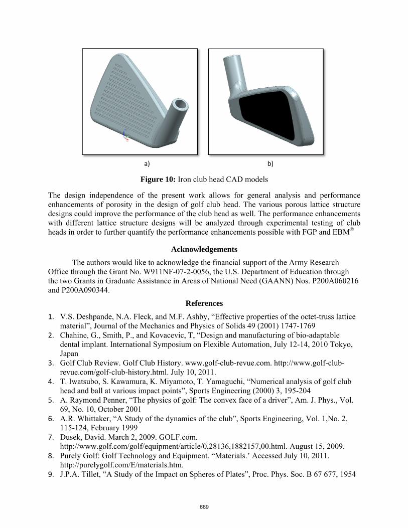
The present work numerically simulates the impact between a porous golf club head and a steel ball in order to determine the COR and contact time. Experimental results using the Trackman Pro, the industry preferred golf swing and ball flight simulator system, will be carried out to verify the results determined numerically with ANSYS LS-DYNA software. The Trackman Pro will provide data, such as ball spin, launch trajectory, initial velocity, club head velocity, ball flight distance, and how far the ball rolls after contact with the ground allowing for the exact performance benefits of porosity to be quantified. The production of club heads incorporating porosity will be manufactured using Arcam’s A2 EBM machine from CAD models designed with Siemens NX 7.5, shown in Figure 10. The black region in Figure 10b is the location where the porosity will be located in the club head. The clubface will be 1-mm thick and the volume behind will be porous, extending to the back of the club head as shown in Figure 10b. The club heads will be sand blasted, polished, and attached to golf shafts for experimental swing testing.
668
a) b)
Figure 10: Iron club head CAD models
The design independence of the present work allows for general analysis and performance enhancements of porosity in the design of golf club head. The various porous lattice structure designs could improve the performance of the club head as well. The performance enhancements with different lattice structure designs will be analyzed through experimental testing of club heads in order to further quantify the performance enhancements possible with FGP and EBM®
Acknowledgements
The authors would like to acknowledge the financial support of the Army Research Office through the Grant No. W911NF-07-2-0056, the U.S. Department of Education through the two Grants in Graduate Assistance in Areas of National Need (GAANN) Nos. P200A060216 and P200A090344.
References
1. V.S. Deshpande, N.A. Fleck, and M.F. Ashby, “Effective properties of the octet-truss lattice material”, Journal of the Mechanics and Physics of Solids 49 (2001) 1747-1769
2. Chahine, G., Smith, P., and Kovacevic, T, “Design and manufacturing of bio-adaptable dental implant. International Symposium on Flexible Automation, July 12-14, 2010 Tokyo, Japan
3. Golf Club Review. Golf Club History. www.golf-club-revue.com. http://www.golf-club-revue.com/golf-club-history.html. July 10, 2011.
4. T. Iwatsubo, S. Kawamura, K. Miyamoto, T. Yamaguchi, “Numerical analysis of golf club head and ball at various impact points”, Sports Engineering (2000) 3, 195-204
5. A. Raymond Penner, “The physics of golf: The convex face of a driver”, Am. J. Phys., Vol. 69, No. 10, October 2001
6. A.R. Whittaker, “A Study of the dynamics of the club”, Sports Engineering, Vol. 1,No. 2, 115-124, February 1999
7. Dusek, David. March 2, 2009. GOLF.com. http://www.golf.com/golf/equipment/article/0,28136,1882157,00.html. August 15, 2009.
8. Purely Golf: Golf Technology and Equipment. “Materials.’ Accessed July 10, 2011. http://purelygolf.com/E/materials.htm.
9. J.P.A. Tillet, “A Study of the Impact on Spheres of Plates”, Proc. Phys. Soc. B 67 677, 1954
669
10. W. Peterson, J. McPhee, “Shape optimization of golf clubface using finite element impact models”, Sports Eng (2010) 12:77-85
11. Arcam AB. “EBM Materials.” http://www.arcam.com/technology/ebm-materials.aspx. July 12, 2011.
12. L.J. Gibson, M.F. Ashby, Cellular Solids – Structure and Properties, Cambridge University Press, Cambridge, 1997
13. S. Papetti, F. Avanzini, D. Rocchesso, “Energy and Accuracy Issues in Numerical Simulations of a Non-linear Impact Model”, Proc. Of the 12th Int. Conference on Digital Audio Effects, 2009
14. U. S. Golf Association. “Equipment Rules.” http://www.usga.org/Rule-Books/Rules-on-Clubs-and-Balls/Equipment-Rules/. July 12, 2011.
15. Brian P. Hill, “Analysis of Nonconforming Coefficients of Restitution in Golf Drivers Using a Finite Element Approach”,Rensselaer Polytechnic Institute, Hartford, Connecticut, December 2010
16. J.O. Hallquist, “LS-DYNA Theory Manual”, Livermore Software Technology Corporation, November 2005
17. D. N. Arnold, The Science of a Drive, Notices of the AMS, Vol. 1, No. 4, 498-501, April 2010
670